1
Please refer to page 14-20-62 for
specific product precautions.
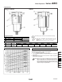
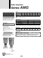
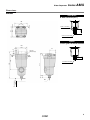
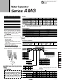
Water Separator
Series AMG
The AMG series water separator is
installed on the air pressure line to
remove water drops in the
compressed air. It is suitable for
use in cases where “water must be
removed, but the air does not have
to be as dry as when an air dryer is
used” or “an air dryer cannot be
used because an electric power
supply is not available”.
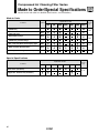
Model
Note)
Rated flow (l /min (ANR))
750
300
Port size
(Nominal size B)
1500
1 8 , 1 4 , 3 8 1 4 ,3 8 ,1 2 3 8 , 1 2 , 3 4
Weight (kg)
0.38
0.55
2200
3500
6000
12000
1 2 ,3 4 ,1
3 4 ,1
1 ,11 2
11 2 , 2
1.4
2.1
4.2
10.5
0.9
Note) Max. flow capacity at a pressure of 0.7 MPa.
Max. flow varies depending on operating pressure. Refer to page 14-20-4 for flow rate and
page 14-20-4 for the max. flow line graph.
Specifications
Through the adoption of an element
that is used exclusively for removing
water drops and the provision of ample
housing interior space, a 99%∗ water
removal rate∗∗ has been achieved.
Compressed air
1.0 MPa
0.05 MPa
1.5 MPa
5 to 60°C
99%
2 years or when pressure drop reaches 0.1 MPa
Fluid
Max. operating pressure
Min. operating pressure ∗
Proof pressure
Ambient and fluid temperature
Removed rate of water
Element life
Caution
Water separator can remove water droplets, but it
cannot remove moisture.
AMG150 AMG250 AMG350 AMG450 AMG550 AMG650 AMG850
Model
∗ 0.1 MPa (N.O. type) or 0.15 MPa (N.C. type) in the case of types with auto-drain.
Refer to “Made to Order Specifications” on page 14-20-55.
∗Condition of inlet air
Pressure: 0.7 MPa
Temperature: 25°C
Relative humidity: 100%
Liquid water content (Water droplet content):
1.5 g/m3 (ANR)
Compressed air flow: Rated flow of each model
∗∗Removed rate of water (%) =
Removed water (Water droplet) (g)
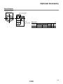
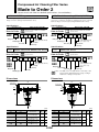
Accessory (Option)
Applicable model
Bracket assembly
With cap bolt and
spring washer
AMG150 AMG250 AMG350 AMG450 AMG550 AMG650 AMG850
BM51
BM53
AMG 250
03 B
1 8 Standard
1 4 Standard
150
250
350 3 8 Standard
450 1 2 Standard
550 3 4 Standard
650 1 Standard
850 11 2 Standard
BM57
AMG
Accessory (Option) ∗
Symbol
Nil
B
C
D
Rc
G
NPT
1 8B
1 4B
3 8B
1 2B
06
10
14
20
Accessory/Option Combinations
Accessory (Option)
Accessory
C D
Option
specifications
J
Available
Misc.
Not available Depends on model
Applicable model
R AMG150 AMG250 AMG350 AMG450 AMG550 AMG650 AMG850
C
D
-J
IN-OUT reversal direction -R
N.C. auto-drain
Accessory
N.O. auto-drain
Drain guide 1 4 B
Option
ID
AM
Note) Refer to “How to Order Bowl Assembly”
on page 14-20-59.
1 1 2B
2B
AT
AFF
3 4B
1B
HA
AMG
Description
—
Bracket
N.C. auto-drain
N.O. auto-drain
∗ Refer to the table below for
accessory/Option combinations.
Port size
01
02
03
04
Drain guide 1/4B female thread
IN-OUT reversal direction
Note) Element service indicator
(symbol: T) is not available
as an option because water
deposits inside the indicator
will lead to malfunctions.
Nil
F
N
JIS Symbol
Be sure to read before handling.
Refer to pages 14-21-3 to 4 for Safety
Instructions and Common Precautions on
the products mentioned in this catalog,
pages 14-14-6 to 8 for Precautions on
every series, and pages 14-20-62 to 64 for
more detailed precautions on every series.
BM56
J
J
R
Thread type
Caution
BM55
Option ∗
Body size
Made to Order Specifications
(For details, refer to page 14-20-55.)
BM54
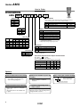
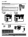
How to Order
x 100
Inflowed water (Water droplet) (g)
Various equipment for drain discharge
BM52
14-20-3
Series
AMG
Flow Characteristics
Element initial condition
Note) Compressed air over max. flow line in the table below may not meet the specifications of the product. It may cause damage to the element.
ine
wl
. flo
x
Ma
AMG450
Max. flow line
Air flow rate (l /min (ANR))
Air flow rate (l /min (ANR))
14B
Max
. flow
AMG550
Pressure drop (MPa)
Pressure drop (MPa)
AMG250
line
34B
Air flow rate (l /min (ANR))
3 8B
1B
AMG650
Pressure drop (MPa)
Pressure drop (MPa)
Max. flow line
Air flow rate (l /min (ANR))
14-20-4
Max. flow line
Air flow rate (l /min (ANR))
11 2 B
AMG850
Max. flow line
Air flow rate (l /min (ANR))
Max. flow line
Air flow rate (l /min (ANR))
AMG350
1 2B
Pressure drop (MPa)
1 8B
Pressure drop (MPa)
Pressure drop (MPa)
AMG150
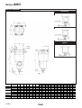
Water Separator
Series
AMG
Construction
AMG850
AMG150 to AMG650
Component Parts
No.
q
w
e
Note) Refer to page 14-20-59 for “How to Order Bowl Assembly”.
Material
Note
Aluminum die-casted
Chrome treated
Aluminum die-casted∗ Epoxy coating on inner surface
Tempered glass
Description
Body
Housing
Sight glass
∗ AMG850 is aluminum casted.
Replacement Parts
No.
Description
Replacement
r
Material
Parts
Element
assembly
Note) Sight glass is indicated in the figure above for easy
understanding of parts, however mounting position is
different.
Refer to dimensions on pages 14-20-6 to 7 for details.
Resin
Others
AMG150
AMG250
AMG350
Model
AMG450
AMG550
AMG650
AMG850
AMG-EL150
AMG-EL250
AMG-EL350
AMG-EL450
AMG-EL550
AMG-EL650
AMG-EL850
∗ Element assembly: With gasket and O-ring
Max. Air Flow
Model Selection
Max. air flow rate (m3/min (ANR))
Select the model in accordance with the following procedure taking
the inlet pressure and max. air flow into consideration.
(Example) Inlet pressure: 0.6 MPa
Maximum air flow rate: 5 m3/min (ANR)
1. Select the point of contact A of inlet pressure and max. air capacity
in the graph.
2. AMG650 is obtained when the max. flow line is above the point of
intersection A in the graph.
Note) Make sure to select a model that has the maximum
flow rate line above the obtained intersecting point.
With a model that has the maximum flow rate line
below the obtained intersecting point, the flow rate will
be exceeded, thus leading to a problem such as being
unable to satisfy the specifications.
HA
AT
ID
AMG
AFF
AM
Misc.
Inlet pressure (MPa)
14-20-5
Series
AMG
AMG150 to AMG650 Dimensions
Accessory
D: With auto-drain (N.O.)
Drain cock: Black
One-touch fitting
C: With auto-drain (N.C.)
Drain cock: Gray
One-touch fitting
∗ N.C. auto-drain not available for AMG650.
Option
J: With drain guide
Bracket
(Option)
Maintenance
space
female thread
Model
AMG150
AMG250
AMG350
AMG450
AMG550
AMG650
14-20-6
Port size
A
(Nominal size B)
1 8 , 1 4, 3 8
159
1 4, 3 8
172
12
178
3 8, 1 2
204
34
210
1 2, 3 4
225
232
1
3 4, 1
259
1 , 11 2
311
Drain
B
C
D
E
F
G
13
13
16
16
19
19
22
22
32
100
113
119
145
151
166
173
200
253
63
76
76
90
90
106
106
122
160
20
20
20
20
20
20
20
20
20
63
76
76
90
90
106
106
122
160
10
10
10
10
10
10
10
10
10
H
166
187
187
218
218
241
241
277
334
I
56
66
66
80
80
90
90
100
150
J
15
20
17
22
19
25
21
30
40
Dimensions with mounting bracket
K
L
M
N
O
P
5
9
5.5 35
54
70
8
12
6
40
66
84
8
12
6
40
66
84
8
14
7
50
80 100
8
14
7
50
80 100
10
14
9
55
88 110
10
14
9
55
88 110
10
16
9
65
102 130
15
20
11
85
136 180
Q
26
28
28
34
34
50
50
60
76
R
4.5
5
5
5
5
9
9
10
12
S
1.6
2.0
2.0
2.3
2.3
3.2
3.2
4.5
4.5
Water Separator
Series
AMG
AMG850 Dimensions
Accessory
D: With auto-drain (N.O. type)
for AMG850
female thread
Bracket
(Option)
HA
Maintenance
space
AT
ID
Drain
AMG
3/8B female
thread
AFF
AM
Misc.
Model
AMG850
Port size
A
(Nominal size B)
1 2, 2
460.5
B
C
D
E
F
G
42
348
220
57.5
220
10
H
463.5
I
180
J
30
Dimensions with mounting bracket
K
L
M
N
O
P
15
24
13
120 184 220
Q
110
R
18
S
6.0
14-20-7
Safety Instructions
These safety instructions are intended to prevent a hazardous situation and/or
equipment damage. These instructions indicate the level of potential hazard by labels of
"Caution", "Warning" or "Danger". To ensure safety, be sure to observe ISO 4414 Note 1),
JIS B 8370 Note 2) and other safety practices.
Caution : Operator error could result in injury or equipment damage.
Warning : Operator error could result in serious injury or loss of life.
Danger :
In extreme conditions, there is a possible result of serious injury or loss of life.
Note 1) ISO 4414: Pneumatic fluid power--General rules relating to systems.
Note 2) JIS B 8370: General Rules for Pneumatic Equipment
Warning
1. The compatibility of pneumatic equipment is the responsibility of the person
who designs the pneumatic system or decides its specifications.
Since the products specified here are used in various operating conditions, their compatibility for the
specific pneumatic system must be based on specifications or after analysis and/or tests to meet your
specific requirements. The expected performance and safety assurance will be the responsibility of the
person who has determined the compatibility of the system. This person should continuously review
the suitability of all items specified, referring to the latest catalog information with a view to giving due
consideration to any possibility of equipment failure when configuring a system.
2. Only trained personnel should operate pneumatically operated machinery
and equipment.
Compressed air can be dangerous if an operator is unfamiliar with it. Assembly, handling or repair of
pneumatic systems should be performed by trained and experienced operators.
3. Do not service machinery/equipment or attempt to remove components until
safety is confirmed.
1. Inspection and maintenance of machinery/equipment should only be performed once measures to
prevent falling or runaway of the driver objects have been confirmed.
2. When equipment is to be removed, confirm the safety process as mentioned above. Cut the supply
pressure for this equipment and exhaust all residual compressed air in the system.
3. Before machinery/equipment is restarted, take measures to prevent shooting-out of cylinder piston
rod, etc.
4. Contact SMC if the product is to be used in any of the following conditions:
1. Conditions and environments beyond the given specifications, or if product is used outdoors.
2. Installation on equipment in conjunction with atomic energy, railway, air navigation, vehicles,
medical equipment, food and beverages, recreation equipment, emergency stop circuits, clutch and
brake circuits in press applications, or safety equipment.
3. An application which has the possibility of having negative effects on people, property, or animals,
requiring special safety analysis.
14-21-3
Common Precautions
Be sure to read before handling.
For detailed precautions on every series, refer to main text.
Selection
Warning
1. Confirm the specifications.
Products represented in this catalog are designed for use in
compressed air appllications only (including vacuum), unless
otherwise indicated.
Do not use the product outside their design parameters.
Please contact SMC when using the products in applications
other than compressed air (including vacuum).
Mounting
Warning
1. Instruction manual
Install the products and operate them only after reading the
instruction manual carefully and understanding its contents.
Also keep the manual where it can be referred to as
necessary.
4. Use clean air
If the compressed air supply is contaminated with chemicals,
cynthetic materials, corrosive gas, etc., it may lead to break
down or malfunction.
Operating Environment
Warning
1. Do not use in environments where the product
is directly exposed to corrosive gases,
chemicals, salt water, water or steam.
2. Do not expose the product to direct sunlight
for an extended period of time.
3. Do not use in a place subject to heavy
vibrations and/or shocks.
4. Do not mount the product in locations where it
is exposed to radiant heat.
Maintenance
2. Securing the space for maintenance
When installing the products, please allow access for
maintenance.
3. Tightening torque
When installing the products, please follow the listed torque
specifications.
Piping
Caution
1. Before piping
Make sure that all debris, cutting oil, dust, etc, are removed
from the piping.
2. Wrapping of pipe tape
When screwing piping or fittings into ports, ensure that chips
from the pipe threads or sealing material do not get inside the
piping. Also, when the pipe tape is used, leave 1.5 to 2 thread
ridges exposed at the end of the threads.
Air Supply
Warning
1. Operating fluid
Please consult with SMC when using the product in
applications other than compressed air (including vacuum).
Regarding products for general fluid, please ask SMC about
applicable fluids.
2. Install an air dryer, aftercooler, etc.
Excessive condensate in a compressed air system may cause
valves and other pneumatic equipment to malfunction.
Installation of an air dryer, after cooler etc. is recommended.
3. Drain flushing
If condensate in the drain bowl is not emptied on a regular
basis, the bowl will over flow and allow the condensate to
enter the compressed air lines.
If the drain bowl is difficult to check and remove, it is
recommended that a drain bowl with the auto-drain option be
installed.
For compressed air quality, refer to “Air Preparation
Equipment” catalog.
14-21-4
Warning
1. Maintenance procedures are outlined in the
operation manual.
Not following proper procedures could cause the product to
malfunction and could lead to damage to the equipment or
machine.
2. Maintenance work
If handled improperly, compressed air can be dangerous.
Assembly, handling and repair of pneumatic systems should
be performed by qualified personnel only.
3. Drain flushing
Remove drainage from air filters regularly. (Refer to the
specifications.)
4. Shut-down before maintenance
Before attempting any kind of maintenance make sure the
supply pressure is shut of and all residual air pressure is
released from the system to be worked on.
5. Start-up after maintenance and inspection
Apply operating pressure and power to the equipment and
check for proper operation and possible air leaks. If operation
is abnormal, please verify product set-up parameters.
6. Do not make any modifications to be product.
Do not take the product apart.
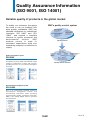
Quality Assurance Information
(ISO 9001, ISO 14001)
Reliable quality of products in the global market
To enable our customers throughout
the world to use our products with
even greater confidence, SMC has
obtained certification for international
standards “ISO 9001” and “ISO
14001”, and created a complete
structure for quality assurance and
environmental
controls.
SMC
products pursue to meet its
customers’ expectations while also
considering company’s contribution in
society.
SMC’s quality control system
Make customers our
first priority, offering
them reliable and
friendly service.
Produce the highest
quality with the
participation of all
employees.
Create new
products using the
latest technology,
and offer the finest
products in a
timely manner.
Quality policies
Market research
Product planning
After service
Sales coordination
Quality management system
ISO 9001
This is an international standard for quality control
and quality assurance. SMC has obtained a large
number of certifications in Japan and overseas,
providing assurance to our customers throughout
the world.
Quality system
education
Training of
suppliers
Research
Education
Design
Training
Development
Production
New product evaluation
Reliability design
Reliability testing
New technical
development
Process control
Inspection, testing, etc.
Initial production control
Quality control activities
Environmental management system
ISO 14001
This is an international standard related to
environmental management systems and
environmental inspections. While promoting
environmentally friendly automation technology,
SMC is also making diligent efforts to preserve
the environment.
14-21-5
SMC Product Conforming to Inter
SMC products complying with EN/ISO, CSA/UL standards are supporting
CE Mark
The CE mark indicates that machines and components meet essential requirements of all the EC Directives
applied.
It has been obligatory to apply CE marks indicating conformity with EC Directives when machines and
components are exported to the member Nations of the EU.
Once “A manufacturer himself” declares a product to be safe by means of CE marking (declaration of
conformity by manufacturer), free distribution inside the member Nations of the EU is permissible.
CE Mark
SMC provides CE marking to products to which EMC and Low Voltage Directives have been applied, in
accordance with CETOP (European hydraulics and pneumatics committee) guide lines.
As of February 1998, the following 18 countries will be obliged to conform to CE mark legislation
Iceland, Ireland, United Kingdom, Italy, Austria, Netherlands, Greece, Liechtenstein, Sweden, Spain, Denmark,
Germany, Norway, Finland, France, Belgium, Portugal, Luxembourg
EC Directives and Pneumatic Components
• Machinery Directive
The Machinery Directive contains essential health and safety requirements for machinery, as applied to
industrial machines e.g. machine tools, injection molding machines and automatic machines. Pneumatic
equipment is not specified in Machinery Directive. However, the use of SMC products that are certified as
conforming to EN Standards, allows customers to simplify preparation work of the Technical Construction File
required for a Declaration of Conformity.
• Electromagnetic Compatibility (EMC) Directive
The EMC Directive specifies electromagnetic compatibility. Equipment which may generate electromagnetic
interference or whose function may be compromised by electromagnetic interference is required to be immune
to electromagnetic affects (EMS/immunity) without emitting excessive electromagnetic affects (EMI/emission).
• Low Voltage Directive
This directive is applied to products, which operate above 50 VAC to 1000 VAC and 75 VDC to 1500 VDC
operating voltage, and require electrical safety measures to be introduced.
• Simple Pressure Vessels Directive
This directive is applied to welded vessels whose maximum operating pressure (PS) and volume of vessel (V)
exceed 50 bar/L. Such vessels require EC type examination and then CE marking.
14-21-6
SMC Product Conforming to International Standards
national Standards
you to comply with EC directives and CSA/UL standards.
Mark of compliance
for CSA/UL
Mark of compliance
for CSA
CSA Standards & UL Standards
UL and CSA standards have been applied in North America (U.S.A. and Canada) symbolizing safety of electric
products, and are defined to mainly prevent danger from electric shock or fire, resulting from trouble with
electric products. Both UL and CSA standards are acknowledged in North America as the first class certifying
body. They have a long experience and ability for issuing product safety certificate. Products approved by CSA
or UL standards are accepted in most states and governments beyond question.
Since CSA is a test certifying body as the National Recognized Testing Laboratory (NRTL) within the
jurisdiction of Occupational Safety and Health Administration (OSHA), SMC was tested for compliance with
CSA Standards and UL Standards at the same time and was approved for compliance with the two Standards.
The above CSA NRTL/C logo is described on a product label in order to indicate that the product is approved
by CSA and UL Standards.
TSSA (MCCR) Registration Products
TSSA is the regulation in Ontario State, Canada. The products that the operating pressure is more than 5 psi
(0.03 MPa) and the piping size is bigger than 1 inch. fall into the scope of TSSA regulation.
Products conforming to CE Standard
With CE symbol for simple visual recognition
In this catalog each accredited product series is indicated with a
CE mark symbol. However, in some cases, every available
models may not meet CE compliance. Please visit our web site
for the latest selection of available models with CE mark.
http://www.smcworld.com
14-21-7
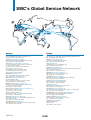
SMC’s Global Service Network
America
Europe
U.S.A. SMC Corporation of America
3011 North Franklin Road Indianapolis, IN 46226, U.S.A.
TEL: 317-899-4440 FAX: 317-899-3102
U.K. SMC Pneumatics (U.K.) Ltd.
Vincent Avenue, Crownhill, Milton Keynes, MK8 0AN, Backinghamshire, U.K.
TEL: 01908-563888 FAX: 01908-561185
CANADA SMC Pneumatics (Canada) Ltd.
6768 Financial Drive Mississauga, Ontario, L5N 7J6 Canada
TEL: 905-812-0400 FAX: 905-812-8686
GERMANY SMC Pneumatik GmbH
Boschring 13-15 D-63329 Egelsbach, Germany
TEL: 06103-4020 FAX: 06103-402139
MEXICO SMC Corporation (Mexico), S.A. DE C.V.
Carr. Silao-Trejo K.M. 2.5 S/N, Predio San Jose del Duranzo
C.P. 36100, Silao, Gto., Mexico
TEL: 472-72-2-55-00 FAX: 472-72-2-59-44/2-59-46
ITALY SMC Italia S.p.A.
Via Garibaldi 62 I-20061 Carugate Milano, Italy
TEL: 02-9271365 FAX: 02-9271365
CHILE SMC Pneumatics (Chile) S.A.
Av. La Montaña 1,115 km. 16,5 P. Norte Parque
Industrial Valle Grande, Lampa Santiago, Chile
TEL: 02-270-8600 FAX: 02-270-8601
ARGENTINA SMC Argentina S.A.
Teodoro Garcia 3860 (1427) Buenos Aires, Argentina
TEL: 011-4555-5762 FAX: 011-4555-5762
BOLIVIA SMC Pneumatics Bolivia S.R.L.
Avenida Beni Numero 4665
Santa Cruz de la Sierra-Casilla de Correo 2281, Bolivia
TEL: 591-3-3428383 FAX: 591-3-3449900
VENEZUELA SMC Neumatica Venezuela S.A.
Apartado 40152, Avenida Nueva Granada, Edificio Wanlac,
Local 5, Caracas 1040-A, Venezuela
TEL: 2-632-1310 FAX: 2-632-3871
FRANCE SMC Pneumatique S.A.
1 Boulevard de Strasbourg, Parc Gustave Eiffel, Bussy Saint Georges, F-77600
Marne La Vallee Cedex 3 France
TEL: 01-64-76-10-00 FAX: 01-64-76-10-10
SWEDEN SMC Pneumatics Sweden AB
Ekhagsvägen 29-31, S-141 05 Huddinge, Sweden
TEL: 08-603-07-00 FAX: 08-603-07-10
SWITZERLAND SMC Pneumatik AG
Dorfstrasse 7, Postfach 117, CH-8484 Weisslingen, Switzerland
TEL: 052-396-3131 FAX: 052-396-3191
AUSTRIA SMC Pneumatik GmbH (Austria)
Girakstrasse 8, A-2100 Korneuburg, Austria
TEL: 0-2262-6228-0 FAX: 0-2262-62285
SPAIN SMC España, S.A.
Zuazobidea 14 Pol. Ind. Júndiz 01015 Vitoria, Spain
TEL: 945-184-100 FAX: 945-184-510
PERU (Distributor) IMPECO Automatizacion Industrial S.A.
AV. Canevaro 752, Lince, Lima, Peru
TEL: 1-471-6002 FAX: 1-471-0935
IRELAND SMC Pneumatics (Ireland) Ltd.
2002 Citywest Business Campus, Naas Road, Saggart, Co. Dublin, Ireland
TEL: 01-403-9000 FAX: 01-466-0385
URUGUAY (Distributor) BAKO S.A.
Galicia 1650 esq. Gaboto C.P. 11200, Montevideo, Uruguay
TEL: 2-401-6603 FAX: 2-409-4306
NETHERLANDS (Associated company) SMC Pneumatics BV
De Ruyterkade 120, NL-1011 AB Amsterdam, Netherlands
TEL: 020-5318888 FAX: 020-5318880
BRAZIL SMC Pneumaticos Do Brasil Ltda.
Rua. Dra. Maria Fidelis, nr. 130, Jardim Piraporinha-Diadema-S.P.
CEP: 09950-350, Brasil
TEL: 11-4051-1177 FAX: 11-4071-6636
GREECE (Distributor) S.Parianopoulos S.A.
7, Konstantinoupoleos Street 11855 Athens, Greece
TEL: 01-3426076 FAX: 01-3455578
COLOMBIA (Distributor) Airmatic Ltda.
Calle 18 69-05 Apart. Aereo 081045 Santa Fe de Bogotá, Colombia
TEL: 1-424-9240 FAX: 1-424-9260
DENMARK SMC Pneumatik A/S
Knudsminde 4 B DK-8300
Odder, Denmark
TEL: 70252900 FAX: 70252901
14-21-20
SMC’s Global Service Network
Europe
Oceania/Asia
FINLAND SMC Pneumatics Finland OY
PL72, Tiistinniityntie 4, SF-02231 ESP00, Finland
TEL: 09-8595-80 FAX: 09-8595-8595
AUSTRALIA SMC Pneumatics (Australia) Pty.Ltd.
14-18 Hudson Avenue Castle Hill NSW 2154, Australia
TEL: 02-9354-8222 FAX: 02-9894-5719
NORWAY SMC Pneumatics Norway A/S
Vollsveien 13C, Granfoss Næringspark N-1366 LYSAKER, Norway
TEL: 67-12-90-20 FAX: 67-12-90-21
NEW ZEALAND SMC Pneumatics (New Zealand) Ltd.
8C Sylvia Park Road Mt.Wellington Auckland, New Zealand
TEL: 09-573-7007 FAX: 09-573-7002
BELGIUM (Distributor) SMC Pneumatics N.V./S.A.
Nijverheidsstraat 20 B-2160 Wommelgem Belguim
TEL: 03-355-1464 FAX: 03-355-1466
TAIWAN SMC Pneumatics (Taiwan) Co.,Ltd.
17, Lane 205, Nansan Rd., Sec.2, Luzhu-Hsiang, Taoyuan-Hsien, TAIWAN
TEL: 03-322-3443 FAX: 03-322-3387
POLAND SMC Industrial Automation Polska Sp.z.o.o.
ul. Konstruktorska 11A, PL-02-673 Warszawa, Poland
TEL: 022-548-5085 FAX: 022-548-5087
HONG KONG SMC Pneumatics (Hong Kong) Ltd.
29/F, Clifford Centre, 778-784 Cheung, Sha Wan Road, Lai Chi Kok, Kowloon,
Hong Kong
TEL: 2744-0121 FAX: 2785-1314
TURKEY (Distributor) Entek Pnömatik San.ve Tic. Ltd. Sti
Perpa Tic. Merkezi Kat:11 No.1625 80270 Okmeydani Istanbul, Türkiye
TEL: 0212-221-1512 FAX: 0212-221-1519
RUSSIA SMC Pneumatik LLC.
36/40 Sredny prospect V.O. St. Petersburg 199004, Russia
TEL: 812-118-5445 FAX: 812-118-5449
CZECH SMC Industrial Automation CZ s.r.o.
Hudcova 78a, CZ-61200 Brno, Czech Republic
TEL: 05-4121-8034 FAX: 05-4121-8034
HUNGARY SMC Hungary Ipari Automatizálási kft.
Budafoki ut 107-113 1117 Budapest
TEL: 01-371-1343 FAX: 01-371-1344
ROMANIA SMC Romania S.r.l.
Str. Frunzei, Nr. 29, Sector 2, Bucharest, Romania
TEL: 01-3205111 FAX: 01-3261489
SLOVAKIA SMC Priemyselná automatizáciá, s.r.o
Nova 3, SK-83103 Bratislava
TEL: 02-4445-6725 FAX: 02-4445-6028
SLOVENIA SMC Industrijska Avtomatilca d.o.o.
Grajski trg 15, SLO- 8360 Zuzemberk, Slovenia
TEL: 07388-5240 FAX: 07388-5249
SOUTH AFRICA (Distributor) Hyflo Southern Africa (Pty.) Ltd.
P.O.Box 240 Paardeneiland 7420 South Africa
TEL: 021-511-7021 FAX: 021-511-4456
EGYPT (Distributor) Saadani Trading & Ind. Services
15 Sebaai Street, Miami 21411 Alexandria, Egypt
TEL: 3-548-50-34 FAX: 3-548-50-34
SINGAPORE SMC Pneumatics (S.E.A.) Pte. Ltd.
89 Tuas Avenue 1, Jurong Singapore 639520
TEL: 6861-0888 FAX: 6861-1889
PHILIPPINES SHOKETSU SMC Corporation
Unit 201 Common Goal Tower, Madrigal Business Park,
Ayala Alabang Muntinlupa, Philippines
TEL: 02-8090565 FAX: 02-8090586
MALAYSIA SMC Pneumatics (S.E.A.) Sdn. Bhd.
Lot 36 Jalan Delima1/1, Subang Hi-Tech Industrial Park, Batu 3 40000 Shah Alam
Selangor, Malaysia
TEL: 03-56350590 FAX: 03-56350602
SOUTH KOREA SMC Pneumatics Korea Co., Ltd.
Woolim e-BIZ Center (Room 1008), 170-5, Guro-Dong, Guro-Gu,
Seoul, 152-050, South Korea
TEL: 02-3219-0700 FAX: 02-3219-0702
CHINA SMC (China) Co., Ltd.
7 Wan Yuan St. Beijing Economic & Technological Development Zone 100176, China
TEL: 010-67882111 FAX: 010-67881837
THAILAND SMC Thailand Ltd.
134/6 Moo 5, Tiwanon Road, Bangkadi, Amphur Muang, Patumthani 12000, Thailand
TEL: 02-963-7099 FAX: 02-501-2937
INDIA SMC Pneumatics (India) Pvt. Ltd.
D-107 to 112, Phase-2, Extension, Noida, Dist. Gautaim Budh Nagar,
U.P. 201 305, India
TEL: (0120)-4568730 FAX: 0120-4568933
INDONESIA (Distributor) P.T. Riyadi Putera Makmur
Jalan Hayam Wuruk Komplek Glodok Jaya No. 27-28 Jakarta 11180 Indonesia
TEL: 021-625 5548 FAX: 021-625 5888
PAKISTAN (Distributor) Jubilee Corporation
First Floor Mercantile Centre, Newton Road Near Boulton Market P.O. Box 6165
Karachi 74000 Pakistan
TEL: 021-243-9070/8449 FAX: 021-241-4589
ISRAEL (Distributor) Baccara Automation Control
Kvutzat Geva 18915 Israel
TEL: 04-653-5960 FAX: 04-653-1445
SAUDI ARABIA (Distributor) Assaggaff Trading Est.
P.O. Box 3385 Al-Amir Majed Street, Jeddah-21471, Saudi Arabia
TEL: 02-6761574 FAX: 02-6708173
14-21-21
Water Separator
Series AMG
Model
Can remove water droplets in compressed air. Use this product in cases where “water must be avoided,
but not so dry as when an air dryer is
used”.
Through the adoption of an element
that is exclusively used for removing
water droplets and the ample housing interior space, a 99%∗ water removal rate∗∗ has been achieved.
Caution
Water separator can remove water droplets, but
it cannot remove moisture.
∗ Condition of inlet air
Pressure: 0.7 MPa
Temperature: 25°C
Relative humidity: 100%
Liquid water content (Water droplet
content): 15 g/m3 (ANR)
Compressed air flow: Rated flow of each
model
∗∗ Water removal rate (%) =
Removed water (Water droplet) (g)
x 100
Inflowed water (Water droplet) (g)
Modular connection is possible
with AMG150C to 550C.
Model
AMG150C AMG250C AMG350C AMG450C AMG550C AMG650 AMG850
Note)
Rated flow (l/min (ANR))
Port size
Mass (kg)
300
750
1500
2200
3700
1 8, 1 4
1 4, 3 8
3 8, 1 2
1 2, 3 4
3 4, 1
0.38
0.55
0.9
1.4
2.1
6000
12000
11 2
1 1 2, 2
10.5
1,
4.2
Note) Max. flow at 0.7 MPa.
Max. flow varies depending on the operating pressure. Refer to “Flow Characteristics” (page 5)
and “Maximum Air flow” (page 6).
Specifications
Fluid
Max. operating pressure
Min. operating pressure∗
Proof pressure
Ambient and fluid temperature
Water removal rate
Element life
Compressed air
1.0 MPa
0.05 MPa
1.5 MPa
5 to 60°C
99%
2 years or when pressure drop reached 0.1 MPa
∗ With auto drain: 0.1 MPa (N.O. type) or 0.15 MPa (N.C. type)
Accessory
Applicable model
AMG150C AMG250C AMG350C AMG450C AMG550C AMG650 AMG850
Bracket assembly
AM-BM101 AM-BM102 AM-BM103 AM-BM104 AM-BM105
BM56
BM57
(with 2 mounting screws)
Caution
Be sure to read this before handling.
Refer to back pages 1 and 2 for Safety Instructions, “Precautions for
Handling Pneumatic Devices” (M-03-E3A) for Common Precautions,
and back pages 3 through to 7 for Specific Product Precautions.
(For details, refer to page 61.)
AMG150C to 550C
AMG650/850
Symbol
AMG
Made to Order
(For details, refer to page 67.)
2
Series AMG
How to Order
AMG150C to 550C
AMG 550C
10
Body size
Made to Order
150C
250C
350C
450C
550C
(“How to Order” and the applicable models are different from those
shown on this page. Be sure to refer to “Made to Order”.)
Symbol
Nil
X15
X26
Description
—
With IN-OUT flange
N.C., N.O. auto drain, drain piping type
Page for details
—
P.69
P.70
Thread type
Symbol
Nil
F
N
Option ∗3
Type
Rc
G∗1
Symbol
Nil
NPT
F
H
J
R
V
∗1 Conforms to
ISO1179-1.
Port size
Symbol Size
01
02
03
04
06
10
Applicable body size
Description
—
Rubber material: Fluororubber
For medium air pressure (1.6 MPa)
Drain guide 1/4 female threaded ∗4
IN-OUT reversal direction
Degreasing wash,∗5 white vaseline
∗4 Drain piping and piping for a stop valve such
as ball valve are required.
∗5 Only body/housing is degreasing washed.
150C 250C 350C 450C 550C
1/8
1/4
3/8
1/2
3/4
1
Auto drain ∗3
Symbol
Nil
Accessory
Symbol
Nil
B
Description
—
Bracket ∗2
∗2 Bracket is included,
(but not assembled).
C
D
Description
Drain cock (Without auto drain)
N.C. auto drain
N.O. auto drain
∗3 Refer to “Auto Drain Specifications/
Option Combinations”.
Auto Drain Specifications/Option Combinations
: Available
: Not available
: Plural options cannot be selected.
(i.e. Combinations such as C-FV, D-FHV are not possible.)
Symbol
Auto drain specifications
Nil
F
H
R
V
C
D
J
Options
Symbol F: Rubber material: Fluororubber
Fluororubber is used for the parts
such as O-ring and gasket.
Symbol R: IN-OUT reversal direction
Air flow in the separator is changed to
right to left.
(Air flow direction of the standard: Left
to right.)
3
Symbol H: For medium air pressure
(1.6 MPa)
Can be used up to 1.6 MPa at
maximum.
Symbol V: Degreasing wash,
white vaseline
Body/housing is degreasing washed. The
lubrication grease for O-ring and gasket is
changed to white vaseline.
Symbol J: Drain guide 1/4 female threaded
Can be pipied to the
drain exhaust port.
1/4 female threaded
Series AMG
Water Separator
How to Order
AMG650/850
AMG 650
10
Body size
Made to Order
650
850
(“How to Order” and the applicable models are different from those
shown on this page. Be sure to refer to “Made to Order”.)
Symbol
Nil
Thread type
Symbol
Nil
F
N
X15
X26
X12
Type
Rc
G
NPT
Size
Symbol
Nil
10
14
20
1
11 2
2
Applicable body size
650
J
R
850
B
Description
—
Bracket ∗1
∗1 Bracket is included,
(but not assembled).
Description
—
Drain guide 1 4 female threaded ∗4
IN-OUT reversal direction
∗4 Drain piping and piping for a stop valve such
as ball valve are required.
Note) Element service indicator (symbol: T) is not
available as an option because water
deposits inside the indicator could lead to
malfunctions.
Accessory
Symbol
Nil
Page for details
—
P.69
P.70
P.70
Option ∗2
Port size
Symbol
Description
—
With IN-OUT flange
N.C., N.O. auto drain, drain piping type
White vaseline
Auto drain ∗2
Symbol
Nil
D
Description
Drain cock (Without auto drain) ∗3
N.O. auto drain
∗2 Refer to “Auto Drain Specifications/Option
Combinations”.
∗3 Body size 850 is equipped with a ball valve
(Rc3/8 female threaded). Mount a piping adapter
IDF-AP609 (page 62) to the ball valve if NPT3/8
female threaded is required.
Note) Refer to “How to Order Bowl Assembly” on page 63.
Auto Drain Specifications/Option Combinations
Auto drain specifications
Auto drain specifications/Option
Auto drain specifications N.O. auto drain
Drain guide 1 4
Option
IN-OUT reversal
direction
D
: Available
Option
J
R
: Not available
Applicable model
AMG650 AMG850
D
J
R
4
Series AMG
Flow Characteristics
Note) Compressed air over max. flow line in the table below may not meet the specifications of the product.
It may cause damage to the element.
AMG150C
AMG450C
AMG850
x
Ma
Pressure drop (MPa)
ine
wl
. flo
Pressure drop (MPa)
Pressure drop (MPa)
Max. flow line
Air flow rate (l /min (ANR))
AMG250C
Air flow rate (l/min (ANR))
AMG550C
low
f
ax.
line
M
Pressure drop (MPa)
Pressure drop (MPa)
Max. flow line
Air flow rate (l /min (ANR))
AMG350C
Air flow rate (l/min (ANR))
AMG650
Pressure drop (MPa)
Pressure drop (MPa)
Max. flow line
Air flow rate (l /min (ANR))
5
Max. flow line
Air flow rate (l/min (ANR))
Max. flow line
Air flow rate (m3/min (ANR))
Water Separator
Series AMG
Construction
AMG150C to 550C, AMG650
q
IN
AMG850
OUT
IN
OUT
r
w
e
Component Parts
No.
Material
Description
1
Body
Aluminum die-casted
2
Housing
Aluminum die-casted∗
3
Sight glass
Tempered glass
Note) Refer to “How to Order Bowl Assembly” on page 63.
Note
Chrome treated
Epoxy coating on
inner surface
—
Note) Sight glass is indicated in the figure for easy understanding
of component parts. However, it differs from the actual
construction. Refer to dimensions on pages 7 through to 9
for details.
∗ The AMG850 is aluminum casted.
Replacement Parts
No. Description
4
Material
Applicable
model
Element Resin, Except option F
assembly others For option F
Model
AMG150C
AMG250C
AMG350C
AMG450C
AMG550C
AMG650
AMG850
AMG-EL150
AMG-EL150-F
AMG-EL250
AMG-EL250-F
AMG-EL350
AMG-EL350-F
AMG-EL450
AMG-EL450-F
AMG-EL550
AMG-EL550-F
AMG-EL650
—
AMG-EL850
—
∗ Element assembly: With gasket (1 pc.) and O-ring (1 pc.)
∗ Refer to back page 6 for replacement of auto drain.
∗ Element assemblies for Made to Order (X12, X15, X20, X26) are same as those for standard (see the above table).
Maximum Air Flow
Model Selection
Max. air flow rate (m3/min (ANR))
Select a model in accordance with the following procedure taking the
inlet pressure and the max. air flow rate into consideration.
(Example) Inlet pressure: 0.6 MPa
Max. air flow rate: 5 m3/min (ANR)
1. Obtain the intersecting point A of inlet pressure and max. air flow
rate in the graph.
2. The AMG650 is obtained when the max. flow line is above the interecting point A in the graph.
Note) Make sure to select a model that has the max. flow line above
the obtained intersecting point. With a model that has the max.
flow line below the obtained intersecting point, the flow rate will
be exceeded, thus leading to a problem such as being unable to
satisfy the specifications.
Inlet pressure (MPa)
6
Series AMG
Dimensions
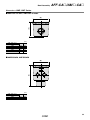
AMG150C to 550C
Auto drain
C: With auto drain (N.C.)
D: With auto drain (N.O.)
34
Drain cock
Gray: N.C.
Black: N.O.
O
F
R
S
P
Q
ø10 one-touch fitting
Combination of D: With auto drain (N.O.)
and H: For medium air pressure
D
I
L
Bracket
(Accessory)
N
M
U
K
T
IN
20
B
J
øV
OUT
C
1/4 female threaded
A
H
Option
Maintenance
space
G
E
J: Drain guide 1/4 female threaded
Drain
20
M5
1/4 female threaded
(mm)
Bracket related dimensions
Model
Port size
A
B
C
D
E
F
G
H
I
J
K
T
U
L
M
V
N
O
P
Q
R
AMG150C
AMG250C
AMG350C
AMG450C
AMG550C
1/8, 1/4
158
10
99
63
20
63
10
173
56
20
5
6
6
12
6
10
35
54
70
26
4.5 1.6
1/4, 3/8
172
14
113
76
20
76
10
190
66
24
8
6
6
12
6
10
40
66
80
28
5
2
3/8, 1/2
204
18
145
90
20
90
10
222
80
28
8
7
7
14
7
12
50
80
95
34
5
2.3
1/2, 3/4
225
20
166
106
20
106
10
246
90
31
10
9
9
18
9
15
55
88
111
50
9
3.2
3/4, 1
259
24
200
122
20
122
15
278
100
33
10
9
9
18
9
15
65
102
126
60
10
3.2
7
S
Water Separator
Series AMG
Dimensions
AMG650
Auto drain
D: With auto drain (N.O.)
180
12
76
34
136
160
4.5
Drain cock: Black
ø10 one-touch fitting
Option
J: Drain guide 1/4 female threaded
160
85
11
32
Bracket
(Accessory)
40
15
150
20
OUT
253
20
IN
Drain
M5
Maintenance
space
10
20
311
334
1/4 female threaded
8
Series AMG
Dimensions
AMG850
Auto drain
D: With auto drain (N.O.)
for AMG850
23
220
184
18
6
220
110
3/8 female threaded
Bracket
(Accessory)
24
13
120
42
30
15
220
180
OUT
Maintenance
space
10
58
464
461
348
IN
9
Drain
Rc 3/8 female threaded
Series AMF
Spacer for Modular Connection
Select a spacer from those listed below when combining modular type AFF2C to
22C, AM150C to 550C. The spacer must be ordered separately.
(Note: Spacer with bracket (Y200T to Y600T) cannot be used.)
Caution
Modular connection
Mount the attached bracket on one side when connecting 2 sets.
Mount the attached brackets on both sides when connecting 3 sets or
more.
As a guideline for the number of brackets, one bracket should be
mounted for every 2 products.
Combination examples of modular applicable products
Arrangement example
AMH250C-B
AME250C
Y300
Arrangement example
1 pc.
1 pc.
1 pc.
AMH250C-B
AME250C
AMF250C-B
Y300
Spacer: Y300
Bracket
1 pc.
1 pc.
1 pc.
2 pcs.
190
172
240
172
190
158
AME250C
AME250C
156
AMF250C-B
236
AMH250C-B
AMH250C-B
Spacer
D
Y200
Y400
B
RELEASE
1
C
Center of IN/OUT ports
X-X
X
2
X
Seal
Model
A
B
C
D
Model
Y200
Y300
Y400
Y500
Y600
3
35.5
18.5
48
4
47
26
59
5
57
31
65
5
61
33
75
6
75.5
41
86
AFF2C, AM150C
AFF4C, AM250C
AFF8C, AM350C
AFF11C, AM450C
AFF22C, AM550C
A
(Spacer width)
Replacement Parts
61
Description
Material
Seal
HNBR
Part no.
Y200
Y300
Y400
Y500
Y600
Y200P-061S
Y300P-060S
Y400P-060S
Y500P-060S
Y600P-060S
Optional Accessory
Piping Adapter
E (Width across flats)
Female thread side B
Male
thread side A
D
C
Dimensions
Thread type and port size
Part no.
Male thread Female thread
side A
side B
IDF-AP609
R 3/8
NPT 3/8
(mm)
C
D
E Material
30
15
22
Brass
62
Bowl Assembly
AFF-CA/AM -CA
Bowl Assembly
Bowl assembly for the AFF and AM series can be replaced without removing the main body from piping if the drain exhaust specification is to be
changed from the drain cock type to the auto drain type or if the bowl has been damaged.
How to Order Bowl Assembly
AFF2C to 22C, AM, AMD, AMH, AMG150C to 550C
AM CA
Option
Body size
Symbol
Nil
150C
250C
350C
450C
550C
F
H
V
Description
—
Rubber material: Fluororubber
For medium air pressure (1.6 MPa)
Degreasing wash, white vaseline
Thread type Note 2)
Drain exhaust
Symbol
A
C
D
J
Description
With drain cock
With N.C. auto drain
With N.O. auto drain
With drain guide Note 1)
Note 1) Drain piping and piping for a
stop valve such as a ball
valve are required.
Symbol
Nil
F Note 3)
N
Type
Rc
G
NPT
Note 2) Corresponded to the drain exhaust
symbol C, D and J. Select according to
the body thread type.
Note 3) Not corresponded to the drain exhaust
symbol C and D.
Select no symbol when the body thread
symbol is F.
Applicable Model
Bowl assembly model
Applicable model
AFF2C, AM150C, AMD150C, AMH150C, AMG150C
AFF4C, AM250C, AMD250C, AMH250C, AMG250C
AFF8C, AM350C, AMD350C, AMH350C, AMG350C
AFF11C, AM450C, AMD450C, AMH450C, AMG450C
AFF22C, AM550C, AMD550C, AMH550C, AMG550C
AM-CA150C
AM-CA250C
AM-CA350C
AM-CA450C
AM-CA550C
Auto Drain Specifications/
Option Combinations
: Available
: Not available
: Plural options cannot be selected.
(i.e. Combinations such as C-FV, D-FHV are not
possible.)
Symbol
AFF37B/75B
AFF CA 37B
Body size
37B
75B
Thread type Note 3)
Symbol
Nil
F Note 4)
N
Drain exhaust
Symbol
A
D
J
Description
With drain cock Note 1)
With N.O. auto drain
With drain guide Note 2)
Type
Rc
G
NPT
Note 3) Corresponded to the drain exhaust symbol D and J.
Select according to the body thread type.
Note 4) Not corresponded to the drain exhaust symbol C and D.
Select no symbol when the body thread symbol is F.
Note 1) Body size 75B is equipped with a ball valve (Rc3/8 female threaded).
Mount a piping adapter IDF-AP609 (page 62) to the ball valve if NPT3/8 female threaded is required.
Note 2) Drain piping and piping for a stop valve such as a ball valve are required.
For body size 75B, substitute with a ball valve. (symbol: A)
63
A
C
D
J
F
H
V
Bowl Assembly
AFF-CA /AM -CA How to Order Bowl Assembly
AM, AMD, AMH, AMG Series
AM CA 650
AMD
AMH
AMG
Thread type Note 3)
Symbol
Nil
F
N
Body size
Type
Rc
G
NPT
Note 3) Corresponded to the drain exhaust
symbol D and J. Select according to
the body thread type.
650
850
Drain exhaust
Symbol
A
D
J
Description
With drain cock Note 1)
With N.O. auto drain
With drain guide Note 2)
Note 1) Body size 850 is equipped with a ball valve
(Rc3/8 female threaded). Mount a piping
adapter IDF-AP609 (page 62) to the ball
valve if NPT3/8 female threaded is required.
Note 2) Drain piping and piping for a stop valve such
as a ball valve are required.
For body size 850, substitute with a ball
valve. (symbol: A)
AME, AMF150C to 550C
AME CA
A
Option Note)
Body size
150C
250C
350C
450C
550C
Symbol
Nil
F
H
V
Description
—
Rubber material: Fluororubber
For medium air pressure (1.6 MPa)
Degreasing wash, white vaseline
Note) Combination of FH is not available.
Applicable Model
Bowl assembly model
AME-CA150C
AME-CA250C
AME-CA350C
AME-CA450C
AME-CA550C
Applicable model
AME150C, AMF150C
AME250C, AMF250C
AME350C, AMF350C
AME450C, AMF450C
AME550C, AMF550C
AME, AMF650/850
AME CA 650
AMF Body size
A
650
850
64
AFF-CA /AM -CA Dimensions: AFF, AM, AMD, AMH, AMG Series
Size: AFF2C to 22C, AFF37B, AM150C to 550C, AM650
(B)
(B)
20
34
20
(C)
(A)
Note 1)
(A)
Note 1)
20
(A)
Note 1)
M5 female
threaded
(B)
(B)
1/4 female threaded
Drain
1/4 female threaded
Note 2) For Rc, G: ø10
For NPT: 3/8
Drain
Drain
Drain
Auto drain for
medium air pressure
Drain guide
Drain cock
Auto drain
(mm)
AFF series
Size
AM, AMD, AMG, AMH series
Size
A
B
C
2C
4C
8C
11C
22C
37B
150C
250C
350C
450C
550C
650
134
139
162
178
202
245
63
76
90
106
122
160
148
153
176
192
216
259
Note 1) Model no. labels are not affixed to the AM-CA150C to 550C.
Note 2) Select according to the body thread type.
Applicable tubing size for one-touch fitting
Rc, G: ø10
NPT: ø3/8 inch
Size: AFF75B, AM850
(220)
(58)
23
(379)
(344)
266
266
(220)
3/8 female threaded
Drain
Rc 3/8
65
Drain
Bowl Assembly
AFF-CA /AM -CA Dimensions: AME, AMF Series
AME150C to 550C, AMF150C to 550C
(A)
(B)
(mm)
AME, AMF series
Size
A
B
150
250
350
450
550
60
70
90
104
130
63
76
90
106
122
AME650/850, AMF650/850
(A)
(B)
(mm)
AME, AMF series
Size
A
B
650
850
225
319
160
120
66
Compressed Air Cleaning Filter Series
Made to Order/Special Specifications
Please consult with SMC for detailed specifications, size and delivery.
Made to Order
Applicable model
Contents
Symbol
AFF
1. With Differential Pressure Gauge
(GD40-2-01)
2. With Differential Pressure Switch
(With Indicator)
AM
AMD
AME
AMF
AMG
AMH
Reference
page
X6
P.68
X37
3. With IN-OUT Flange
X15
4. With Pressure Differential Gauge
(GD40-2-01), IN-OUT Flange
X17
5. N.C., N.O. Auto Drain, Drain Piping Type
X26
6. White Vaseline Specifications
X12
7. Mist Separator for High Flow Rate (0.3 μm)
X13
P.69
P.70
P.71
Special Specifications
Applicable model
Contents
AFF
AM
AMD
AME
AMF
AMG
AMH
Reference
page
Clean Series (10-Series)
P.72
Copper-free, Fluorine-free (20-Series)
67
Compressed Air Cleaning Filter Series
Made to Order 2
Please consult with SMC for detailed specifications, size and delivery.
3. With IN-OUT Flange
4. With Differential Pressure Gauge (GD40-2-01), IN-OUT Flange
Makes flange piping easier when filter ports on IN and OUT are
flange connection. (Flange material: Carbon steel)
The differential pressure gauge is mounted on the main body to monitor the life of a filter by checking its clogging status. Ports on IN and
OUT are flange connection type. (Flange material: Carbon steel)
Specifications
Specifications
AFF11C, 22C, 37B, 75B
Applicable model
∗ Refer to “How to Order” for standard
specifications.
How to Order
X15
AFF
Body size∗
Option∗
(Not applicable with H)
Auto drain∗
Thread type∗
Port size∗
AFF11C, 22C, 37B, 75B
Applicable model
How to Order
X17
AFF
Body size∗
Option∗
(Not applicable with
F, H, S, T, U, V)
Auto drain∗
Thread type∗
Port size∗
Accessory∗
Specifications
∗ Refer to “How to Order” for standard
specifications.
Accessory∗
Specifications
Applicable AM450C, 550C, 650, 850, AMD450C, 550C, 650, 850,
model
AMH450C, 550C, 650, 850, AMG450C, 550C, 650, 850
∗ Refer to “How to Order” for standard
specifications.
How to Order
X15
AM
AMD
AMG
AMH
Option∗
(Not applicable with H)
Auto drain∗
Body size∗
Thread type∗
Accessory∗
Port size∗
Applicable
model
AM450C, 550C, 650, 850, AMD450C, 550C, 650, 850,
AMH450C, 550C, 650, 850
How to Order
∗ Refer to “How to Order” for standard
specifications.
X17
AM
AMD
AMH
Option∗
(Not applicable with
F, H, S, T, U, V)
Auto drain∗
Body size∗
Thread type∗
Port size∗
Accessory∗
Note) • The AMG series is not applicable since water drops could
ingress inside its differential pressure gauge, resulting in
malfunction or damage to the product.
Dimensions
Dimensions
C
A
Connection
B
Connection
IN
OUT
OUT
B
A
IN
Drain
Drain
(mm)
(mm)
AFF series
Size
AM, AMD, AMG, AMH series
Size
11C
450C
22C
550C
69
37B
650
75B
850
Connection
15(1/2B), 20(3/4B), 25(1B)
JIS 10K FF flange
20(3/4B), 25(1B)
JIS 10K FF flange
25(1B), 40(1 1 2 B)
JIS 10K FF flange
40(1 1 2 B), 50(2B)
JIS 10K FF flange
AFF series AM, AMD, AMH series
Size
Size
A
B
240
255
11C
450C
260
297
22C
550C
300
349
37B
650
380
497
75B
850
Connection
15(1/2B), 20(3/4B), 25(1B)
JIS 10K FF flange
20(3/4B), 25(1B)
JIS 10K FF flange
25(1B), 40(1 1 2 B)
JIS 10K FF flange
40(1 1 2 B), 50(2B)
JIS 10K FF flange
A
B
305
C
240
339
260
80
391
300
541
380
Compressed Air Cleaning Filter Series
Made to Order 3
Please consult with SMC for detailed specifications, size and delivery.
5. N.C., N.O. Auto Drain, Drain Piping Type
6. White Vaseline Specifications
Drain piping type (drain guide specification) to the drain exhaust from
N.C. auto drain and N.O. auto drain. N.C. type is not available for the
AFF37B and AM650.
Changed the grease for O-rings and gaskets as lubricant to white
vaseline.
Specifications
Specifications
AFF2C to 22C, 37B
Applicable model
∗ Refer to “How to Order” for standard
specifications.
How to Order
X26
AFF
Body size∗
Thread type∗
Port size∗
Accessory∗
AFF37B, 75B
Applicable model
Option∗
(Drain cock, drain guide and
F, H, V are not applicable.)
Auto drain∗
(Available for N.C., N.O. auto
drain only)
∗ Refer to “How to Order” for standard
specifications.
How to Order
X12
AFF
Body size∗
Option∗
Thread type∗
Auto drain∗
Port size∗
Accessory∗
Specifications
Specifications
AM150 to 650
Applicable model
Applicable
model
∗ Refer to “How to Order” for standard
specifications.
How to Order
X26
AM
AMD
AMG
AMH
Option∗
(Drain cock, drain guide and
F, H, V are not applicable.)
Auto drain∗
(Available for N.C., N.O. auto
drain only)
Body size∗
Thread type∗
Port size∗
Accessory∗
AM650, 850, AMD650, 850, AME650, 850,
AMF650, 850, AMG650, 850, AMH650, 850
∗ Refer to “How to Order” for standard
specifications.
How to Order
AM
AMD
AME
AMF
AMG
AMH
X12
Option∗
Auto drain∗
Accessory∗
Port size∗
Thread type∗
Body size∗
20
(A)
Dimensions
1/4 female threaded
Drain
(mm)
AFF series
Size
AM, AMD, AMG, AMH series
Size
Port size
A
2C
4C
8C
11C
22C
37B
150C
250C
350C
450C
550C
650
1/8, 1/4
1/4, 3/8
3/8, 1/2
1/2, 3/4
3/4, 1
1, 1 1 2
159
172
204
225
259
311
70
Compressed Air Cleaning Filter Series
Special Specifications
Please consult with SMC for detailed specifications, size and delivery.
Clean Series (10-Series)
Copper-free, Fluorine-free (20-Series)
Clean Series products are used in cleaner environments such as in
clean rooms as compared to a general factory environment. For further details, refer to the Clean Series catalog.
To eliminate effects on color CRTs, etc. by copper ion or fluorine
resin, copper materials are electroless-nickel plated or changed to
copper-free materials to prevent the generation of copper ions.
(It is not applicable to the AMD, AME, AMF and AMH series because
those include fluorine resin in the filter material of the element.)
Specifications
Specifications
AFF2C to 22C, 37B, 75B
Applicable model
∗ Refer to “How to Order” for standard
specifications.
How to Order
10 AFF
How to Order
With drain guide Note 1)
Nil
F
H
R
T
—
Rubber material: Fluororubber
For medium air pressure (1.6 MPa)
IN-OUT reversal direction
With element service indicator
Note 2) Combination of FT is not
available.
F and H are only applicable to
the AFF2C to 22C.
Note 1) “10-” is not applicable to
standard product (with
drain cock) and with
auto drain.
C
D
Body size∗
Thread type∗
Note)
Port size∗
Accessory
Symbol Description
—
Nil
Bracket
B
Option Note 2)
Accessory Note)
Symbol Description
—
Nil
Bracket
B
∗ Refer to “How to Order” for standard
specifications.
20 AFF
J
Body size∗
Thread type∗
Port size∗
AFF2C to 22C, 37B
Applicable model
R
T
Note) “20-” is only applicable with N.C. auto drain (C) or N.O. auto drain
(D). Drain cock and drain guide are copper-free, fluorine-free as
standard.
Specifications
AFF75B
Applicable model
Specifications
Applicable AM150C to 550C, 650, 850, AMD150C to 550C, 650, 850,
model
AMH150C to 550C, 650, 850
10 AM
AMD
AMH
Body size∗
Thread type∗
—
Rubber material: Fluororubber
For medium air pressure (1.6 MPa)
IN-OUT reversal direction
With element service indicator
Nil
F
H
R
T
Note 2) Combination of FT is not
available.
F and H are only applicable to
the AM150C to 550C.
Note 1) “10-” is not applicable to
standard product (with
drain cock) and with
auto drain.
Specifications
AME150C to 550C, 650, 850,
AMF150C to 550C, 650, 850
Applicable model
10 AME
AMF
Symbol
Nil
B
Accessory
Description
—
Bracket
Thread type∗
With drain guide Note 1)
Option Note 2)
Accessory Note)
Symbol Description
—
Nil
Bracket
B
Body size∗
Thread type∗
Port size∗
20 AFF75B
J
Port size∗
Option Note)
—
IN-OUT
reversal direction
With element
service indicator
Nil
Specifications
Port size∗
Accessory
Symbol
Description
—
Nil
Bracket
B
N.O. auto drain
D
Option
—
IN-OUT
reversal direction
With element
service indicator
Nil
R
T
AM150C to 550C, 650, AMG150C to 550C, 650
Applicable model
C
D
20 AM
AMG
Body size∗
Thread type∗
Port size∗
Accessory
Symbol Description
—
Nil
Bracket
B
Note)
Nil
R
T
Option Note)
—
IN-OUT
reversal direction
With element
service indicator
Note) “20-” is only applicable with N.C. auto drain (C) or N.O. auto drain
(D). Drain cock and drain guide are copper-free, fluorine-free as
standard.
Specifications
Applicable model
Option Note)
Nil
F
H
R
—
Rubber material: Fluororubber
For medium air pressure (1.6 MPa)
IN-OUT reversal direction
Note) F and H are only applicable to the
AME, AMF150C to 550C.
AM850, AMG850
20 AM 850
AMG
Thread type∗
Port size∗
Accessory
Symbol
Description
—
Nil
Bracket
B
N.O. auto drain
D
Nil
R
T
Option
—
IN-OUT
reversal direction
With element
service indicator
72
Related Products:
Auto Drain Valve
Series AD402/600
Model/Specifications
Drain is automatically discharged in
a reliable manner, without requiring
human operators.
Highly resistant to dust and corrosion, operates reliably, and a bowl
guard is provided as standard
equipment.
Model
Proof pressure
Max. operating pressure
Operating pressure range Note)
Ambient and fluid temperature
Port size
Drain port size
Mass (g)
AD402
AD600
1.5 MPa
1.0 MPa
0.1 to 1.0 MPa
–5 to 60°C (No freezing)
1 4, 3 8, 1 2
1.5 MPa
1.0 MPa
0.3 to 1.0 MPa
–5 to 60°C (No freezing)
3 4, 1
3 4, 1
2100
38
620
Note) 400 l/min (ANR) or more
Specific Product Precautions
Be sure to read this before handling.
Refer to back pages 1 and 2 for Safety Instructions, “Precautions
for Handling Pneumatic Devices” (M-03-E3A) for Common Precautions.
AD402
AD600
Selection
JIS Symbol
Piping
Warning
Warning
Use the auto drain under the following operating conditions in order to prevent malfunction.
1) Operate the compressor above 3.7 kw
{400 l/min (ANR)}.
2) Use the AD402 at an operating pressure
above 0.1 MPa and AD600 above 0.3
MPa.
Piping should be done under the following
conditions in order to prevent malfunction.
For drain piping, use a pipe whose I.D. is not
less than ø10 and length not more than 5 m.
Avoid riser piping.
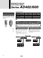
How to Order
AD402
03
Option
Thread type
Nil
N
F
Rc
NPT
G
Symbol
IN
02
03
04
AD600
Nil
—
Metal bowl
Thread type
Nil
N
F
Rc
NPT
G
OUT
Symbol
IN
OUT
14
38
38
38
06
10
34
34
1
1
12
38
2
Port size
Port size
73
06
Related Products: Auto Drain Valve
Series AD402/600
Construction/Dimensions
AD402
AD600
!4 Valve
assembly
q Body
w O-ring
q Body
e Gauze
u Lever
Valve o
w O-ring
Chamber y
i Piston assembly
Float t
!1 Spring
Bowl !0
i Piston
Long hole !2
of chamber
r O-ring
Drain guide !3
Drain
Drain
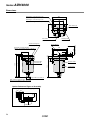
Component Parts
Working Principle (AD402)
• When no pressure is applied inside the bowl !0, float t descends of
its own weight and valve o closes the chamber y hole. Piston i is
pushed down by spring !1, and drain passes through the chamber’s
long hole !2 to enter the housing and is discharged.
• When pressure is applied inside the bowl:
When pressure is 0.1 MPa or more, it overcomes the force of spring
!1, allowing the piston i to ascend, and comes in contact with O-ring
r. Thus, the inside of the bowl !0 is isolated from the outside.
• When drain has accumulated:
Float t ascends due to flotation and opens the chamber hole y,
allowing the pressure to enter the chamber y. Piston i descends due
to internal pressure and the force of spring !1, and the accumulated
drain is discharged through drain guide !3.
No.
Description
1 Body
Material
Aluminum die-casted
Replacement Parts
No.
Description
Material
2
3
O-ring
Gauze
Internal assembly
Piston assembly
NBR
Stainless steel
—
—
Note 1)
8
Model
AD402
AD600
113136
20062
AD34PA
—
JIS B2401G-100
—
—
20025A
Note 1) Internal assembly: Assembly for parts r to !2 except !0.
Note 2) Part no. for bowl assembly: AD34
Note 3) Part no. for bowl !0: 201016
74
Related Products:
Motor Operated Auto Drain
Series ADM200
Model/Specifications
Reliably discharges even highly
viscous drain
• Highly resistant to dust and highly
viscous drain, the valve opens and
closes reliably to discharge the drain.
High drain discharge capacity
• With a large discharge port, a large
amount of drain can be discharged in
a single operation.
• Elimination of residual drain inside
the tank and pipes prevents the generation of foreign matter such as
dried rust or drain, which could adversely affect the equipment located
on the outlet side.
Air
1.0 MPa
1.5 MPa
–5 to 60°C (No freezing)
1 time in a minute (Standard)
2 sec./time (Standard)
100, 200 VAC 50 60 Hz, Other
4W
IN: 3 8, 1 2
OUT: 3 8
550 g
Operating time
Power source
Power consumption
Port size
Mass
∗ If the operating cycle is twice in a minute (operating time 2 sec. x 2) operating time is 4 sec. each minute.
Specific Product Precautions
Low power consumption: 4 W
• A long pipe can also be connected to
the discharge port.
• Can be connected directly to a compressor.
ADM200--
Model
Fluid
Max. operating pressure
Proof pressure
Ambient and fluid temperature
Operating cycle∗
Be sure to read before handling.
Refer to back pages 1 and 2 for Safety Instructions, “Precautions
for Handling Pneumatic Devices” (M-03-E3A) for Common Precautions.
Mounting
Piping
Warning
Warning
1. Install this product after discharging the
drainage that has already accumulated in
the tank. Otherwise, it could lead to malfunction.
2. Install this product, so that the drain port
could face downwards. Otherwise, it could
lead to malfunction.
Piping should be done under the following
conditions in order to prevent malfunction.
For drain piping, use a pipe whose I.D. is not
less than ø5 and length not more than 5
m. Avoid riser piping.
Maintenance
Caution
Provide a stop valve before the ADM200 to
facilitate maintenance and inspection.
Caution
If the valve becomes clogged with debris,
press the manual button to flush out the debris. Otherwise, it could lead to malfunction.
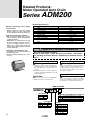
How to Order
ADM200
03 1
Thread type
Nil
Operating time/Applicable compressor
N
F
Rc
NPT
G
Symbol
IN
OUT
03
04
38
12
38
38
Nil
4
6
8
2 sec/min (1 time/min) /3.7 to 37 kW
4 sec/min (2 times/min) /37 to 75 kW
6 sec/min (3 times/min) /75 to 110 kW
8 sec/min (4 times/min) /220 to 370 kW
Port size
75
Voltage
1
2
3
4
5
6
7
100 VAC 50 60 Hz
200 VAC 50 60 Hz
240 VAC 50 60 Hz
110 VAC 50 60 Hz
220 VAC 50 60 Hz
24 VDC
12 VDC
Related Products: Motor Operated Auto Drain
Series ADM200
Mounting Example
Compressor
Aftercooler
Air tank
Main line filter
Air dryer
Construction/Dimensions
e
w
Set screw
r
t
q
y
Manual button
Component Parts
No.
1
2
Description
Body
Cap
Replacement Parts
Material
Aluminum die-casted
Aluminum die-casted
Note
Chrome treated
Chrome treated
No.
Description
3 Note) Motor
4
Cam
5
6
Valve assembly
O-ring
Material
—
Part no.
812PG-voltage
Cast steel
Operating time
201324 (Nil)
201325 (4)
201326 (6)
201327 (8)
Brass, NBR
NBR
20137-1A
S-16
Note) Motor part no. in the case of 100 VAC: 812PG-AC100V
76
Related Products:
Heavy Duty Auto Drain
Series ADH4000
Specifications
Easy maintenance
Float type
Auto drain type
Can maintain without removing the existing
piping.
Auto drain valve type
No need for electric power and no
waste of air.
Proof pressure
Float type auto drain allows automatic drain
discharge without electric power.
Operating pressure range Note)
0.05 to 1.6 MPa
Fluid
Compressed air
Mounting example
Aftercooler
Air tank
Air dryer
N.O. (Normally open: Open in the case of
pressure loss)
2.5 MPa
1.6 MPa
Max. operating pressure
5 to 60°C (With no condensation)
Ambient and fluid temperature <Corrosive gas, flammable gas and organic solvents
are not allowed.>
400 cc/min (Pressure 0.7 MPa, in the case of water)
Max. drain discharge
1.2 kg (With bracket: 1.3 kg)
Mass
White
Paint color
Air compressor
ADH4000
Note) Use for an air compressor with flow more than 50 l/min (ANR).
ADH4000
Accessory (Option)
Description
Bracket set
Ball valve piping set
Part no.
Contents
BM58
Bracket ··························································· 1 pc.
M6 x 10 l (Hexagon socket head cap screw) ··· 2 pcs.
ADH-C400
Ball valve/Rc 1/2 ············································· 1 pc.
Barrel nipple/R 1/2 ·········································· 2 pcs.
Elbow/Rc 1/2 ··················································· 1 pc.
Note) Accessory (Option) is included, but not assembled.
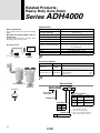
How to Order
Ball valve piping set
Bracket set
JIS Symbol
ADH 4000
04
Heavy duty
auto drain
Accessory (Option)∗
Standard size
Thread type
Nil
Rc
F
N
NPT
G
Thread type
04 1/2 (Female threaded)
77
Symbol
Contents
Note
Nil
None
(Standard)
—
B
Bracket set
C
Ball valve
piping set
—
Not available for
G/NPT threads.
∗ Notes
1) When more than one option is desired,
enter in alphabetical order.
2) Accessory is not assembled.
3) Refer to each drawing of dimensions
and mounting methods for details.
Related Products: Heavy Duty Auto Drain
Series ADH4000
Construction
!1
q
o
i
u
Component Parts
w
No.
1
y
IN
t
r
10-1
e
Description
Body
Material
Note
Aluminum alloy
Baking finish
2
Housing
Aluminum alloy
Baking finish
3
Drain guard
Aluminum alloy
Baking finish
4
Float
5
Pilot valve
6
Lever
Resin
7
Flushing button
Brass
8
Orifice
9
Diaphragm
No.
10-3
10-4
10-5
Stainless steel + Rubber
Rubber
Replacement Parts
10-2
!0
Foam rubber
Description
10
Repair kit for
main valve
11
O-ring
Part no.
Note
ADH-D400
Kit includes parts from
10-1 to 10-5
G85(B)
Material: NBR
Note) When changing parts, follow the operating manual.
Do not disassemble other parts.
OUT
Specific Product Precautions
Be sure to read this before handling. Refer to back pages 1 and 2 for Safety Instructions, “Precautions
for Handling Pneumatic Devices” (M-03-E3A) for Common Precautions.
Design
Caution
1. Use this product in an area
where the air pressure does not
exceed 1.6 MPa.
If exceeding 1.6 MPa, it could lead to
an accident or malfunction.
2. An air pressure of 0.05 MPa and
an air compressor’s discharge
flow rates higher than 50 l/min
(ANR) are required.
Below these values, the air will be exhausted continuously from the drain
exhaust port.
3. Keep the compressed air and the ambient temperature of the location
where this product is installed within
the range of 5 to 60°C. Exceeding this
range could lead to a failure or malfunction.
4. Avoid using this product in an
area where corrosive gases,
flammable gases or organic solvents are contained in the compressed air or in the surrounding air.
Selection
Caution
1. The maximum dischargeable
drainage rate is 400 cc/min.
If using this product in excess of this
value, there could be causing the drain
to flow over to the outlet side.
Piping
Caution
1/2B
1. Use piping of
or larger for
drain inlet and avoid riser piping.
2. For drain piping, use a pipe whose I.D.
is not less than 8 mm and length not
more than 10 m. Do not make any upward angles in drain line. Be sure to
secure exhaust port piping since drain
is under pressure.
Mounting
Caution
1. Install with “out port” down in a
vertical position.
Inclination from the vertical line should
be less than 5°.
2. Install with at least 200 mm of
free space above the unit to allow for maintenance.
3. To place this product near the air compressor, install in such a way that the
vibrations will not be transmitted.
4. Install a valve to drain inlet so
that maintenance is possible.
Use a ball valve with a bore size of
more than 15 mm. (Ball valve piping
set is available as an accessory (option).)
Mounting
Caution
5. When not draining sufficiently, open
the bleed valve so that drain could run
through easily.
Maintenance
Caution
1. Check drain condition periodically (more than once a day).
Also, push the flushing button to open
the exhaust valve.
2. Pilot air is exhausted from the exhaust
port indicated in “Dimensions”. Do not
cover this exhaust port. Clean the
exhaust port so that port is not blocked
by dust, etc.
3. When solid foreign objects exceeding 1
mm come in, the main valve may become blocked. After recovering the internal pressure of this product to 0
MPa (atmospheric pressure), remove
the hexagon socket head cap screw
(M6) from the body part and wash inside with water to remove foreign solid
objects blocking the main valve.
4. When using this product, drain may
not easily enter the product. In such a
case, adjust the open angle of its
bleed valve to lower the pressure a bit
inside the bowl so that drain could run
through easily.
78
Series ADH4000
Dimensions
M6 Hexagon socket head cap screw
[Applicable hexagon wrench key nominal size 5]
M6 Hexagon socket head cap screw
[Applicable hexagon wrench key nominal size 5]
108
100
58
33
100
Pilot exhaust port
Flushing button
Bleed valve
(Refer to “Maintenance” 4.)
Bracket mounting hole
120
Drain inlet 1/2 female threaded
(Refer to “How to Order” for type of thread.)
8
30
10
16
7
200
100
(Maintenance space)
Bracket (Option)
(Both sides)
Model no. label
155
171
189
(176)
Octagonal width
across flats 30
Hexagon width across flats 27
Drain outlet 1/2 female threaded
(Refer to “How to Order” for type of thread.)
Option: Reference Figure of Assembly
Piping example of ball valve piping set
79
(100)
(41)
(54)
(45)
Caution label
Related Products:
Differential Pressure Gauge
Series GD40-2-01
Model/Specifications
The pressure differential at the
inlet and the outlet of compressed
air equipment can be viewed at a
glance on the differential pressure
gauge. It is ideal for the maintenance control of filters.
Compact and lightweight
Can be installed easily by merely
providing a bypass circuit.
Provided with a protective cover to
prevent hazards.
GD40-2-01
Model
Fluid
Max. operating pressure
Proof pressure
Ambient and fluid temperature
Port size Rc
Scale range
Accuracy
Dial size
Mass (g)
Main Parts Material
Case
Internal part
Window
Scale plate
Zinc die-casted
Brass, Phosphor bronze
Polyester
Stainless steel
Compressed air
1 MPa
1.5 MPa
5 to 60°C
1/8
0 to 0.2 MPa
±0.006 MPa
ø40
300
Accessory
Nylon tube
Male connector
Male elbow
T0425 (0.5 m)
H04-01 (1 pc.)
DL04-01 (1 pc.)
Specific Product Precautions
Be sure to read this before handling.
Refer to back pages 1 and 2 for Safety Instructions, “Precautions
for Handling Pneumatic Devices” (M-03-E3A) for Common Precautions.
Design
Caution
JIS Symbol
Piping Example
1. This product cannot be used in a
location where pulsations could
occur frequently.
Dimensions
Mounting
Caution
1. Mounting
1) The HIGH and LOW marks on the back of the
differential pressure gauge indicate the high
pressure and low pressure sides respectively.
Connect the HIGH side to the inlet side of the
filter or other devices and the LOW side to their
outlet side. Do not use a stop valve to prevent
damage to the differential pressure gauge if the
valve is inadvertently left open or closed.
2) Install the differential pressure gauge vertically.
3) The piping of the differential pressure gauge
must be connected securely because it will
break if it becomes detached.
Thread for mounting bracket
Low pressure side
Pressure gauge
Inlet side
Outlet side
High pressure side
Thread depth 7
80
Safety Instructions
These safety instructions are intended to prevent hazardous situations and/or equipment damage.
These instructions indicate the level of potential hazard with the labels of “Caution,” “Warning” or
“Danger.” They are all important notes for safety and must be followed in addition to International
Standards (ISO/IEC), Japan Industrial Standards (JIS)∗1) and other safety regulations∗2).
∗ 1) ISO 4414: Pneumatic fluid power – General rules relating to systems.
ISO 4413: Hydraulic fluid power – General rules relating to systems.
IEC 60204-1: Safety of machinery – Electrical equipment of machines. (Part 1: General requirements)
ISO 10218-1992: Manipulating industrial robots -Safety.
JIS B 8370: General rules for pneumatic equipment.
JIS B 8361: General rules for hydraulic equipment.
JIS B 9960-1: Safety of machinery – Electrical equipment of machines. (Part 1: General requirements)
JIS B 8433-1993: Manipulating industrial robots - Safety.
etc.
∗ 2) Labor Safety and Sanitation Law, etc.
Caution: Operator error could result in injury or equipment damage.
Warning: Operator error could result in serious injury or loss of life.
Danger : In extreme conditions, there is a possibility of serious injury or loss of life.
Warning
1. The compatibility of the product is the responsibility of the person who designs the equipment
or decides its specifications.
Since the product specified here is used under various operating conditions, its compatibility with specific equipment must be
decided by the person who designs the equipment or decides its specifications based on necessary analysis and test results.
The expected performance and safety assurance of the equipment will be the responsibility of the person who has determined
its compatibility with the product. This person should also continuously review all specifications of the product referring to its
latest catalog information, with a view to giving due consideration to any possibility of equipment failure when configuring the
equipment.
2. Only personnel with appropriate training should operate machinery and equipment.
The product specified here may become unsafe if handled incorrectly. The assembly, operation and maintenance of machines or
equipment including our products must be performed by an operator who is appropriately trained and experienced.
3. Do not service or attempt to remove product and machinery/equipment until safety is confirmed.
1. The inspection and maintenance of machinery/equipment should only be performed after measures to prevent falling or
runaway of the driven objects have been confirmed.
2. When the product is to be removed, confirm that the safety measures as mentioned above are implemented and the power
from any appropriate source is cut, and read and understand the specific product precautions of all relevant products
carefully.
3. Before machinery/equipment is restarted, take measures to prevent unexpected operation and malfunction.
4. Contact SMC beforehand and take special consideration of safety measures if the product is to
be used in any of the following conditions.
1. Conditions and environments outside of the given specifications, or use outdoors or in a place exposed to direct sunlight.
2. Installation on equipment in conjunction with atomic energy, railways, air navigation, space, shipping, vehicles, military,
medical treatment, combustion and recreation, or equipment in contact with food and beverages, emergency stop circuits,
clutch and brake circuits in press applications, safety equipment or other applications unsuitable for the standard
specifications described in the product catalog.
3. An application which could have negative effects on people, property, or animals requiring special safety analysis.
4. Use in an interlock circuit, which requires the provision of double interlock for possible failure by using a mechanical protective
function, and periodical checks to confirm proper operation.
Back page 1
Safety Instructions
Caution
The product is provided for use in manufacturing industries.
The product herein described is basically provided for peaceful use in manufacturing industries.
If considering using the product in other industries, consult SMC beforehand and exchange specifications or a contract
if necessary. If anything is unclear, contact your nearest sales branch.
Limited Warranty and Disclaimer/Compliance Requirements
The product used is subject to the following “Limited Warranty and Disclaimer” and “Compliance
Requirements”. Read and accept them before using the product.
Limited Warranty and Disclaimer
1. The warranty period of the product is 1 year in service or 1.5 years after the product is delivered.∗3)
Also, the product may have specified durability, running distance or replacement parts. Please
consult your nearest sales branch.
2. For any failure or damage reported within the warranty period which is clearly our responsibility,
a replacement product or necessary parts will be provided.
This limited warranty applies only to our product independently, and not to any other damage
incurred due to the failure of the product.
3. Prior to using SMC products, please read and understand the warranty terms and disclaimers
noted in the specified catalog for the particular products.
∗ 3) Vacuum pads are excluded from this 1 year warranty.
A vacuum pad is a consumable part, so it is warranted for a year after it is delivered.
Also, even within the warranty period, the wear of a product due to the use of the vacuum pad or failure due to the
deterioration of rubber material are not covered by the limited warranty.
Compliance Requirements
When the product is exported, strictly follow the laws required by the Ministry of Economy, Trade
and Industry (Foreign Exchange and Foreign Trade Control Law).
Back page 2
Series AM /AFF
Specific Product Precautions 1
Be sure to read this before handling. Refer to back pages 1 and 2 for Safety Instructions,
and “Precautions for Handling Pneumatic Devices” (M-03-E3A) for Common Precautions.
Design
Caution
Warning
1. Design the layout so that the mist separator should
be installed in an area that is less susceptible to
pulsations.
1. Hold the female thread side and tighten to the recommended torque when screwing in the piping material.
The element could be damaged if a difference between the
inlet pressure and the outlet pressure exceeds 0.1 MPa.
Insufficient tightening torque may cause loosening or defective sealing. Over-tightening torque may damage the thread
etc. If it is tightened without holding the female thread side,
excessive force will be directly applied to the piping bracket
resulting in a product failure.
2. Be careful of dust generation by the pneumatic
equipment mounted on the outlet side.
When installing pneumatic equipment on the outlet side of the
AM series, dust particles may come off from outlet equipment, which will lower the cleanliness of compressed air. Consider this impact upon the cleanliness of compressed air when
installing pneumatic equipment on the outlet side.
3. About when to use N.C. auto drain and N.O. auto
drain.
Recommended Torque
Unit: N · m
Connection
1/8
1/4
3/8
1/2
3/4
1
11 2
2
thread
Torque 1.5 to 2 7 to 9 12 to 14 28 to 30 28 to 30 36 to 38 48 to 50 48 to 50
∗ After tightening manually, tighten additionally by about 1/6 turn with a
tightening tool.
When using the AFF2C to 22C, 37B, 75B, AM150C to
550C, 650, 850 with normally open (N.O.) auto drain, air may
ceaselessly blow out of the drain discharge area when an air
compressor with a small air discharge volume is used since
the valve does not close unless the air pressure is 0.1 MPa or
higher. Therefore, when using a compressor for 3.7 kW or
less, make sure to use the normally closed (N.C.) auto drain.
The minimum operating pressure is 0.15 MPa even with N.C.
auto drain.
4. Use a tubing with proper size and length for drain
piping of auto drain.
When using the AFF2C to 22C, 37B, AM150C to 550C, 650
with auto drain:
Normally closed (N.C.) Use tubing O.D. 10 mm and keep
Normally open (N.O.)
the whole length within 5 m.
When using the AFF75B and AM850 with auto drain:
Normally open (N.O.): Use tubing I.D. 9 mm or more and
keep the whole length within 2.8 m.
2. Do not apply torsional moment or bending moment
(except the product's own weight) to the bracket. It
may damage the bracket. Support external piping
separately.
5. Provide a design that prevents back pressure and
back flow.
Back pressure or back flow may damage an element.
6. Keep the certificate of Class 2 Pressure Vessel in a
safe place.
Products below are subject to Class 2 Pressure Vessel Act.
Certificate will be sent in 2 to 4 weeks later after the shipment
of the product.
Main Line Filter ················ AFF220A
Micro Mist Separator········ AMD90/100/91
3. Inflexible piping such as steel piping tends to be
affected by spread of excessive moment load or vibration from the piping side. Lay flexible tubing between the steel pipe and the product to prevent
such effects.
Back page 3
Series AM /AFF
Specific Product Precautions 2
Be sure to read this before handling. Refer to back pages 1 and 2 for Safety Instructions,
and “Precautions for Handling Pneumatic Devices” (M-03-E3A) for Common Precautions.
Selection
Caution
Piping
Caution
1. About the system composition of purifying compressed air
1. Connect it with IN and OUT ports in proper location.
It does not work with the connection reversed.
Compressed air generally contains particulate contaminants
as listed below, though there are some variations due to the
compressor type and specifications. Determine the system
configuration according to the desired cleanliness of compressed air and application, while referring to the “Air Preparation Equipment Selection Guide” for the AM series (Best
Pneumatics).
[Particulate contaminants in compressed air]
• Water (drainage)
• Dust sucked from ambient air
• Degenerated oil from compressor
• Solid foreign matter such as rust inside piping and oil
In the case of the AFF2C to 22C, 37B, 75B, AM150C to
550C, 650, 850
Verify the direction of the flow of the compressed air and the
“ ” or “ ” mark that indicates the inlet of the product before
connecting. It cannot be used if connected in the opposite direction.
IN
Symbol which indicates the flow of
compressed air
or
2. Select according to the maximum flow consumption.
OUT
When compressed air is used for air blow, etc., find the maximum air consumption before selecting the size of the AM
series. (If compressed air exceeding the maximum flow rate is
supplied, it can result in decline of the cleanliness of compressed air or element damage.)
Mounting
Caution
1. About the mounting orientation of the products
Make sure to install this product on horizontal piping. If it is installed diagonally, laterally, or upside down, the drain separated by the element will splash to the outlet side.
In the case of the AFF75A to 220A, AMD801, 901, 800, 900,
1000
INLET and OUTLET of compressed air is labeled on the side
of flange. Be sure to connect correctly.
2. Use an air blower to flush the piping before connecting the piping.
Use an air blower to thoroughly flush the piping, or wash the
piping to remove any cutting chips, cutting oil, or debris from
inside the piping before connecting them.
3. Wrapping of sealant tape
When screwing in the pipes or fittings, make sure to prevent
cutting chips or the sealant material on the threaded portion of
the pipe from entering the piping. If sealant tape is to be used,
leave about 1.5 to 2 ridges of threads uncovered.
4. Modular connection
Mount the attached bracket on one side when connecting 2
sets. Mount the attached brackets on both sides when connecting 3 sets or more. As a guideline for the number of
brackets, one bracket should be mounted for every 2 products.
Back page 4
Series AM /AFF
Specific Product Precautions 3
Be sure to read this before handling. Refer to back pages 1 and 2 for Safety Instructions,
and “Precautions for Handling Pneumatic Devices” (M-03-E3A) for Common Precautions.
Air Supply
Caution
Maintenance
Caution
1. The mist separator is not applicable to gases other
than compressed air.
1. Replace the element immediately when the time for
its replacement has arrived.
The mist separator is not applicable to gases other than compressed air (example: oxygen, hydrogen, flammable gas,
mixed gas).
To replace the element, replace the O-ring and the gasket,
too. For the replacement procedure, refer to the operating
manual. (For element dimensions, refer to back page 6.)
<Element replacement>
In the case of the AFF2C to 22C, 37B, 75B, AM150C to
550C, 650, 850
The replacement interval for the element is when the pressure
drop reaches 0.1 MPa or after two years of operation, whichever comes first. A pressure drop can be verified with the element service indicator (-T) or with differential pressure gauge
(Made to Order).
In the case of the AFF75A to 220A, AMD800 to 1000,
AMD801, 901
The replacement interval for the element is when the pressure
drop reaches 0.1 MPa or after one year of operation, whichever comes first. Confirm the pressure drop with a pressure
gauge. (With pressure gauge: -G)
2. Do not use compressed air that contains chemicals,
organic solvents, salt, or corrosive gases.
Do not use compressed gas containing chemicals, organic
solvents, salt or corrosive gas. This can cause rust, damage
to rubber and resin parts, or malfunction.
3. Operate within the specified operating pressure
range.
Damage, failure, or malfunction may occur if the mist separator is operated above the maximum operating pressure.
If the mist separator is used below the minimum operating
pressure, increase in the air-flow resistance due to clogging
will have such influence that the desired flow rate cannot be
obtained.
If the mist separator is used under a low pressure such as for
a blower, conduct sufficient tests by users to confirm the specifications and performances.
Operating Environment
Caution
1. Do not use in the following environments, as this
can cause failure.
1) In locations having corrosive gases, organic solvents, and
chemical solutions, or in locations where these elements
are likely to adhere to the equipment.
2) In locations where salt water, water, or water vapor could
come in contact with the equipment.
3) In locations that is exposed to shocks and vibrations.
2. Be careful about the contamination of the workpieces due to entrainment of the ambient air.
If compressed air is used for air blow, compressed air blowing
out from the blow nozzle may entrain foreign matter (solid particles and liquid particles) floating in the ambient air, blowing it
against the workpieces and causing adhesion. Therefore, sufficient precautions must be taken about the ambient environment.
Back page 5
2. Be sure to exhaust the drain accumulated in the filter container.
Failure to discharge the drain will allow the accumulated drain
to flow over to the outlet side.
When using the AFF2C to 22C, 37B, 75B, AM150C to
550C, 650, 850 with drain cock, drain guide or ball valve, discharge the drain before the drainage level reaches the center
of the sight glass. If the drain is not discharged properly, it will
flow over to the outlet side.
Sight glass
Drainage level
Discharge the drain before
reaching the center level.
Series AM /AFF
Specific Product Precautions 4
Be sure to read this before handling. Refer to back pages 1 and 2 for Safety Instructions,
and “Precautions for Handling Pneumatic Devices” (M-03-E3A) for Common Precautions.
Maintenance
Others
Caution
Caution
1. Element interchange
• The auto drain operates when the drainage level reaches the
top of the sight glass, and the drain will be discharged.
• When using the AFF2C to 22C, 37B, AM150C to 550C,
650 with auto drain, the drain is automatically discharged
with the knob tightened to the “S” side. Manual drain discharge, however, is also possible.
<Manual operation>
A manual knob attached to the auto drain end is tightened to
the “S” side in normal operation. The drain can be discharged
by loosening it to the “O” side. (Be careful, however, if pressure remains inside the filter when the drain is discharged, the
drain will blow out from the drain port.)
Following is the element dimensions for the AFF and AM
series:
Since elements for the same body size has the same dimensions, they are interchangeable.
However, do not interchange them easily since it can cause
various kinds of problems.
If interchanging the elements is unavoidable, replace the
product model number label, too.
B
3. In the case of a type with auto drain
øA
Element Dimensions
Model
O
Open
S
Close
4. The drain exhaust parts replacement method and
necessary parts are different depending on when it
was manufactured.
Necessary parts
Manufactured
Manufactured
Applicable
Description
Dec. 2002 or before
Jan. 2003 onwards
size
[Up to manufacturing [Manufacturing lot No.
lot No. GZ]
HO onwards]
AM-SA002
Drain cock
2C to 22C
Drain guide
AM-SA003
2B to 37B
Auto drains cannot be
150C to 550C
AD43PA-D
N.O. auto drain replaced alone since
150 to 650
those cannot be
assembled without
dedicated assembly
tools. The entire bowl
2C to 22C
assembly must be
2B to 22B
AD53PA-D
N.C. auto drain replaced. (Refer to
150C to 550C
150 to 550
“How to Order Bowl
Assembly” on page
63.)
Ball valve set
N.O. auto drain
AM-SA004
AD34PA-D Note)
75B, 850
AFF2C, AFF2B, AM150C, AM150
AMD150C, AMD150, AMH150C, AMH150
AFF4C, AFF4B, AM250C, AM250
AMD250C, AMD250, AMH250C, AMH250
AFF8C, AFF8B, AM350C, AM350
AMD350C, AMD350, AMH350C, AMH350
AFF11C, AFF11B, AM450C, AM450
AMD450C, AMD450, AMH450C, AMH450
AFF22C, AFF22B, AM550C, AM550
AMD550C, AMD550, AMH550C, AMH550
AFF37B, AM650
AMD650, AMH650
AFF75B, AM850
AMD850, AMH850
Element dimensions
(Reference value)
øA
B
49
42
58
52
70
78
82
88
96
118
122
144
142
223
2. About oil-free products
The AFF and AM series includes parts (such as resin parts,
rubber parts, and elements) that does not allow degreasing
wash. Therefore, oil-free products with all parts degreasing
washed is not available.
3. Degreasing wash
Certain parts such as the body and housing can be degreasing washed. Contact SMC after confirming the specifications.
(available as Option or Made to Order)
4. Change of oil
On the AFF and AM series, no oil such as grease is applied
to parts exposed to compressed air. However, for certain
specifications, there are some parts to which oil is applied.
It is possible to change the type of applied oil (as Option or
Made to Order).
Note) Jig (AM-SA005) for replacing auto drain is necessary for the 75B or 850.
Back page 6
Series AM /AFF
Specific Product Precautions 5
Be sure to read this before handling. Refer to back pages 1 and 2 for Safety Instructions,
and “Precautions for Handling Pneumatic Devices” (M-03-E3A) for Common Precautions.
Others
Caution
5. Internal volume of filter container
The product can be used as a small capacity air tank by removing the element.
Following is the volume of filter containers of the AFF and
AM series (when the element is removed).
Volume Inside Filter
Volume inside filter
(Reference value)
(cm3)
Model
AFF2C, AFF2B, AM150C, AM150
AMD150C, AMD150, AMH150C, AMH150
AFF4C, AFF4B, AM250C, AM250
AMD250C, AMD250, AMH250C, AMH250
AFF8C, AFF8B, AM350C, AM350
AMD350C, AMD350, AMH350C, AMH350
AFF11C, AFF11B, AM450C, AM450
AMD450C, AMD450, AMH450C, AMH450
AFF22C, AFF22B, AM550C, AM550
AMD550C, AMD550, AMH550C, AMH550
AFF37B, AM650
AMD650, AMH650
AFF75B, AM850
AMD850, AMH850
250
300
600
1000
1500
3000
9000
Discontinued Model and Equivalent Model
The AFF and AM series were remodeled to products introduced in this catalog in 1988.
Along with the new models, old models were provided mainly for the purpose of maintenance. However, due to the aging of metal dies
and extreme decline in the quantity, the procurement of parts and consequently the maintenance of the production system became difficult. For this reason, old models were discontinued in 1994, as detailed in the table below. Use the equivalent model listed there.
Discontinued Model and Equivalent Model
Product name
Main Line Filter
Mist Separator
Micro Mist
Separator
Odor Removal
Filter
Model
AFF6
AFF22
AFF37
AFF55
AM200
AM300
AM400
AM500
AM600
AMD100
AMD200
AMD300
AMD400
AMD500
AMD600
AMF200
AMF300
AMF400
AMF500
AMF600
Production discontinuance
Period of production
Period of
discontinuance
production
for maintenance
discontinuance
parts
for products
End of July '94
End of March '99
Equivalent model
External dimensions
of product
Width x Depth x Height
Model
External dimensions
of product
Width x Depth x Height
100 x 100 x 253
150 x 140 x 446
200 x 170 x 526
280 x 280 x 497
63 x 63 x 191
85 x 85 x 258
120 x 120 x 236
140 x 140 x 383
180 x 170 x 465
63 x 63 x 136
80 x 82 x 170
90 x 90 x 233
140 x 140 x 380
140 x 140 x 490
140 x 140 x 590
80 x 80 x 153
90 x 90 x 216
140 x 140 x 250
140 x 140 x 360
140 x 140 x 460
AFF4C
AFF22C
AFF37B
AFF75B
AM150C
AM250C
AM350C
AM550C
AM650
AMD150C
AMD250C
AMD350C
AMD450C
AMD550C
AMD650
AMF250C
AMF350C
AMF450C
AMF550C
AMF650
76 x 76 x 172
122 x 122 x 259
160 x 160 x 311
220 x 220 x 461
63 x 63 x 158
76 x 76 x 172
90 x 90 x 204
122 x 122 x 259
160 x 160 x 311
63 x 63 x 158
76 x 76 x 172
90 x 90 x 204
106 x 106 x 225
122 x 122 x 259
160 x 160 x 311
76 x 76 x 103
90 x 90 x 132
106 x 106 x 151
122 x 122 x 187
160 x 160 x 291
Note) Some models have different heights depending on the port size. They are shown in parentheses.
Back page 7
Page
P.10
P.18
P.26
P.52
SMC'S GLOBAL MANUFACTURING, DISTRIBUTION AND SERVICE NETWORK
EUROPE
AUSTRIA
SMC Pneumatik GmbH (Austria)
BELGIUM
SMC Pneumatics N.V./S.A.
BULGARIA
SMC Industrial Automation Bulgaria Eood
CROATIA
SMC Industrijska Automatika d.o.o.
CZECH REPUBLIC
SMC Industrial Automation CZ s.r.o.
DENMARK
SMC Pneumatik A/S
ESTONIA
SMC Pneumatics Estonia OÜ
FINLAND
SMC Pneumatics Finland Oy
FRANCE
SMC Pneumatique SA
GERMANY
SMC Pneumatik GmbH
GREECE
SMC Hellas E.P.E.
HUNGARY
SMC Hungary Ipari Automatizálási Kft.
IRELAND
SMC Pneumatics (Ireland) Ltd.
ITALY
SMC Italia S.p.A.
LATVIA
SMC Pnuematics Latvia SIA
LITHUANIA
UAB “SMC Pneumatics”
NETHERLANDS
SMC Pneumatics B.V.
NORWAY
SMC Pneumatics Norway AS
POLAND
SMC Industrial Automation Polska Sp.z.o.o.
ROMANIA
SMC Romania S.r.l.
RUSSIA
SMC Pneumatik LLC
SLOVAKIA
SMC Priemyselná Automatizácia Spol s.r.o.
SLOVENIA
SMC Industrijska Avtomatika d.o.o.
SPAIN/PORTUGAL
SMC España S.A.
SWEDEN
SMC Pneumatics Sweden AB
SWITZERLAND
SMC Pneumatik AG
U.K.
SMC Pneumatics (U.K.) Ltd.
ASIA
CHINA
SMC (China) Co., Ltd.
HONG KONG
SMC Pneumatics (Hong Kong) Ltd.
INDIA
SMC Pneumatics (India) Pvt. Ltd.
MALAYSIA
SMC Pneumatics (S.E.A.) Sdn. Bhd.
PHILIPPINES
Shoketsu SMC Corporation
SINGAPORE
SMC Pneumatics (S.E.A.) Pte. Ltd.
SOUTH KOREA
SMC Pneumatics Korea Co., Ltd.
TAIWAN
SMC Pneumatics (Taiwan) Co., Ltd.
THAILAND
SMC (Thailand) Ltd.
NORTH AMERICA
CANADA
SMC Pneumatics (Canada) Ltd.
MEXICO
SMC Corporation (Mexico), S.A. de C.V.
U.S.A.
SMC Corporation of America
SOUTH AMERICA
ARGENTINA
SMC Argentina S.A.
BOLIVIA
SMC Pneumatics Bolivia S.r.l.
BRAZIL
SMC Pneumáticos do Brasil Ltda
CHILE
SMC Pneumatics (Chile) S.A.
VENEZUELA
SMC Neumatica Venezuela S.A.
OCEANIA
AUSTRALIA
SMC Pneumatics (Australia) Pty. Ltd.
NEW ZEALAND
SMC Pneumatics (N.Z.) Ltd.
Safety Instructions Be sure to read “Precautions for Handling Pneumatic Devices” (M-03-E3A) before using.
Akihabara UDX 15F,
4-14-1, Sotokanda, Chiyoda-ku, Tokyo 101-0021, JAPAN
Phone: 03-5207-8249 Fax: 03-5298-5362
URL http://www.smcworld.com
© 2008 SMC Corporation All Rights Reserved
Specifications are subject to change without prior notice
and any obligation on the part of the manufacturer.
D-DN
1st printing MT printing MT 16400DN Printed in Japan.
This catalog is printed on recycled paper with concern for the global environment.