1
BHT-202Q/202QW-CE
If you leave the BHT with the battery cartridge discharged or with no battery cartridge
loaded or if you replace the battery cartridge in a wrong way, the BHT may lose the data
stored in it.
Before cold booting (refer to Chapter 2, Section 2.3.5 "Warm and Cold Booting"), it is
recommended that important data be saved into the FLASH folder or uploaded to the
host PC. Cold booting will erase all data stored in the RAM.
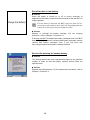
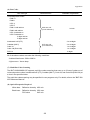
The shape of the projected area marker differs according to the original target market.
This hand-held scanner with built-in area marker should not be used in the United States and
Canada as it does not meet the specifications required for use there.
Copyright © DENSO WAVE INCORPORATED, 2006
All rights reserved. No part of this publication may be reproduced in any form or by any means without
permission in writing from the publisher.
Specifications are subject to change without prior notice.
All products and company names mentioned in this manual are trademarks or registered trademarks of
their respective holders.
The latest precision manufacturing technology yields LCD panels whose pixels are 99.99% defect free.
The downside, note, is that up to 0.01% of the pixels can remain permanently dark or lit on today's
state-of-the-art panels.
A thin Newton's rings (rainbow-like patterns) may appear on the touch screen.
This does not necessarily indicate a problem with the touch screen.
Preface
Please READ through these operating instructions carefully. It will enable you to operate your
BHT-202Q/202QW-CE correctly.
After you have finished reading the instructions, keep this manual handy for speedy reference.
i
How this book is organized
This manual is made up of five chapters and appendices.
Chapter 1 Quick Guide
Describes the basic operating method of the BHT and the related notes.
Chapter 2 Getting Started the BHT and System Mode
Summarizes the BHT system configuration and describes the operation including preparation and
System Mode (which is required for the efficient use of application programs).
Chapter 3 Communications Operations of the BHT-202Q/202QW-CE
Describes the communications operations of the BHT-202Q/202QW-CE—the spread spectrum
communication (BHT-202QW-CE only), infrared communication, USB interface specifications, basic
communications specifications, communication using Ymodem, and ActiveSync--for data transfer with
the host PC or other devices.
Chapter 4 Error Messages
Lists the error messages which will appear on the LCD if some error occurs in the BHT.
Chapter 5 Handling the CU-200 (Option)
Describes the handling procedure of the communication unit CU-200, the interfacing with the host PC,
and the charging of the rechargeable battery cartridge.
Appendix A: Specifications
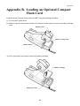
Appendix B: Loading an Optional Compact Flash Card
Appendix C: Quality Assurance Standards
ii
Related Publications
BHT-200 API Reference Manual
Screen Indication
The lettering in the screens in this manual is a little different from that in the actual screens. File names
used are only for description purpose, so they will not appear if you have not set files having those
names.
iii
SAFETY PRECAUTIONS
Be sure to observe all these safety precautions.
Please READ through these instructions carefully. They will enable you to use the BHT and CU
correctly.
Always keep this manual nearby for speedy reference.
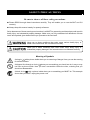
Strict observance of these warnings and cautions is a MUST for preventing accidents that could result in
bodily injury and substantial property damage. Make sure you fully understand all definitions of these
terms and symbols given below before you proceed to the text itself.
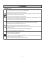
Alerts you to those conditions that could cause serious bodily injury or
death if the instructions are not followed correctly.
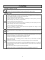
Alerts you to those conditions that could cause minor bodily injury or
substantial property damage if the instructions are not followed correctly.
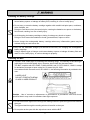
Meaning of Symbols
A triangle ( ) with a picture inside alerts you to a warning of danger. Here you see the warning
for electrical shock.
A diagonal line through a circle ( ) alerts you to something you should not do; it may or may
not have a picture inside. Here you see a screwdriver inside the circle, meaning that you
should not disassemble.
A black circle ( ) with a picture inside alerts you to something you MUST do. This example
shows that you MUST unplug the power cord.
iv
Handling the battery cartridge
• Never disassemble or heat the battery cartridge, nor put it into fire or water; doing so could
cause battery-rupture or leakage of battery fluid, resulting in a fire or bodily injury.
• Do not carry or store the battery cartridge together with metallic ball-point pens, necklaces,
coins, hairpins, etc.
Doing so could short-circuit the terminal pins, causing the batteries to rupture or the battery
fluid to leak, resulting in a fire or bodily injury.
• Avoid dropping the battery cartridge or letting it undergo any shock or impact.
Doing so could cause the batteries to break, generate heat, rupture or burn.
• Never charge the rechargeable battery cartridge where any inflammable gases may be
emitted; doing so could cause fire.
• Only use the dedicated charger (CU-200/CH-201/CH-251) for charging the rechargeable
battery cartridge.
Using a different type of charger could cause battery-rupture or leakage of battery fluid and
result in a fire, bodily injury, or serious damage to property.
Handling the BHT
• The BHT uses a laser light for indicating the scanning range. The intensity of the laser light
might be too low to inflict bodily injury. However, do not look into the laser beam.
The BHT complies with IEC 60825-1:1993+A2:2001 and 21 CFR 1040.10, 1040.11 except
for deviations pursuant to laser notice No. 50, dated July 26, 2001.
In accordance with Clause 8 and 9, IEC 60825-1, the following information is provided to the
user:
LASER LIGHT
DO NOT STARE INTO BEAM
CLASS 2 LASER PRODUCT
Caution - Use of controls or adjustments or performance of procedures other than those
specified herein may result in hazardous laser light exposure.
• Do not look into the light source through the reading window or point the light source towards
the eyes.
The light emitted through the reading window is harmful to the eyes.
• Do not poke at the eyes with the stylus that comes with the BHT.
v
Handling the CU
• If smoke, abnormal odors or noises come from the CU, immediately unplug the AC adapter
from the wall socket or CU and contact your nearest dealer.
Failure to do so could cause fire or electrical shock.
• If foreign material or water gets into the CU, immediately unplug the AC adapter from the wall
socket or CU and contact your nearest dealer.
Failure to do so could cause fire or electrical shock.
• If you drop the CU so as to damage its housing, immediately unplug the AC adapter from the
wall socket or CU and contact your nearest dealer.
Failure to do so could cause fire or electrical shock.
• Never use the CU for charging anything other than the specified battery cartridges.
Doing so could cause heat, battery-rupture, or fire.
• Never bring any metals into contact with the output terminals.
Doing so could produce a large current through the CU, resulting in heat or fire, as well as
damage to the CU.
• Never use the CU on the line voltage other than the specified level.
Doing so could cause the CU to break or burn.
• Use the dedicated AC adapter only.
Failure to do so could result in fire.
• If the power cord of the AC adapter is damaged (e.g., exposed or broken lead wires), stop
using it and contact your nearest dealer.
Failure to do so could result in a fire or electrical shock.
vi
Handling the battery cartridge
• Never charge a wet or damp rechargeable battery cartridge.
Doing so could cause the batteries to break, generate heat, rupture or burn.
Handling the BHT
• If smoke, abnormal odors or noises come from the BHT, immediately turn off the power, pull
out the battery cartridge, and contact your nearest dealer.
Failure to do so could cause smoke or fire.
• If foreign material or water gets into the BHT, immediately turn off the power, pull out the
battery cartridge, and contact your nearest dealer.
Failure to do so could cause smoke or fire.
• If you drop the BHT so as to damage its housing, immediately turn off the power, pull out the
battery cartridge, and contact your nearest dealer.
Failure to do so could cause smoke or fire.
• Do not use batteries or power sources other than the specified ones; doing so could
generate heat or cause malfunction.
Never
disassemble
• Never disassemble or modify the BHT; doing so could result in an accident such as break or
fire.
• Never put the BHT in places where there are excessively high temperatures, such as inside
closed-up automobiles, or in places exposed to direct sunlight.
Doing so could affect the housing or parts, resulting in a fire.
• Avoid using the BHT in extremely humid or dusty areas, or where there are drastic
temperature changes.
Moisture or dust will get into the BHT, resulting in malfunction, fire or electrical shock.
• In environments where static electricity can build into significant charges (e.g., if you wipe off
the plastic plate with a dry cloth), do not operate the BHT. Doing so will result in malfunction
or machine failure.
• Tap the LCD only with the stylus that comes with the BHT.
Using the tip of a pen or any pointed object will result in a damaged or broken LCD.
vii
Handling the CU
• Never disassemble or modify the CU; doing so could result in an accident such as fire or
malfunction.
• Never put the CU in places where there are excessively high temperatures, such as inside
closed-up automobiles, or in places exposed to direct sunlight.
Doing so could affect the housing or parts, resulting in a fire.
• Avoid using the CU in extremely humid or dusty areas, or where there are drastic
temperature changes.
Moisture or dust will get into the CU, resulting in malfunction, fire or electrical shock.
• Never cover or wrap up the CU or AC adapter in a cloth or blanket.
Doing so could cause the unit to heat up inside, deforming its housing, resulting in a fire.
Always use the CU and AC adapter in a well-ventilated area.
• Do not place the CU anyplace where it may be subjected to oily smoke or steam, e.g., near a
cooking range or humidifier.
Doing so could result in a fire or electrical shock.
• Keep the power cord away from any heating equipment.
Failure to do so could melt the sheathing, resulting in a fire or electrical shock.
• Do not insert or drop foreign materials such as metals or anything inflammable through the
openings or vents into the CU.
Doing so could result in a fire or electrical shock.
• If you are not using the CU for a long time, be sure to unplug the AC adapter from the wall
socket for safety.
Failure to do so could result in a fire.
• When caring for the CU, unplug the AC adapter from the wall socket for safety.
Failure to do so could result in an electrical shock.
viii
Proper Care of the BHT and CU
Clean the housings, BHT charge terminals, battery cartridge terminals, and CU-200 charge terminals
with a dry, soft cloth. Before cleaning, be sure to turn the BHT power off and unplug the AC adapter of
the CU.
• Never use benzene, alcohol, or other organic solvents. The
housing may be marred or the paint may come off.
• Never rub or strike the liquid crystal display (LCD) with anything
hard. The LCD surface will be easily scratched or broken.
• When cleaning the keypad, do not scrub the surface too hard,
and do not pull the keys. Doing so may break the keys or cause
the keypad to dislocate.
• If the BHT or CU becomes smudged, moisten a soft cloth with neutral detergent and wring it out
thoroughly. Wipe the BHT or CU with the cloth and then go over it again with a dry cloth.
Dust or dirt accumulating on the clear plate of the reading window will affect reading performance. If you
use the BHT in dusty areas, therefore, periodically check the clear plate of the reading window and clean
it if dusty.
• To clean the plate, first blow the dust away with an airbrush. Then wipe the plate with a cotton swab or
the similar soft one gently.
• If sand or hard particles have accumulated, never rub the plate; doing so will scratch or damage it.
Blow the particles away with an airbrush or a soft brush.
Limited Warranty on Software Products
In no event will DENSO WAVE INCORPORATED be liable for direct, indirect, special, incidental, or
consequential damages (including imaginary profits or damages resulting from interruption of operation
or loss of business information) resulting from any defect in the software or its documentation or
resulting from inability to apply the software or its documentation.
ix
DENSO WAVE INCORPORATED does not assume any product liability arising out of, or in
connection with, the application or use of any product, circuit, or application described herein.
If it is judged by DENSO WAVE INCORPORATED that malfunction of the product is due to the
product having been dropped or subjected to impact, repairs will be made at a reasonable charge
even within the warranty period.
Intellectual Property Precaution
DENSO WAVE INCORPORATED ("DENSO WAVE") takes reasonable precautions to ensure its
products do not infringe upon any patent of other intellectual property rights of other(s), but DENSO
WAVE cannot be responsible for any patent or other intellectual property right infringement(s) or
violation(s) which arise from (i) the use of DENSO WAVE's product(s) in connection or in combination
with other component(s), product(s), data processing system(s) or equipment or software not supplied
from DENSO WAVE; (ii) the use of DENSO WAVE's products in a manner for which the same were not
intended nor designed; or (iii) any modification of DENSO WAVE's products by other(s) than DENSO
WAVE.
x
Chapter 1 Quick Guide
Chapter 2 Getting Started the BHT and System Menu
Chapter 3 Communications Operations
of the BHT-202Q/202QW
Chapter 4 Error Messages
Chapter 5 Handling the CU-200 (Option)
Appendices
Chapter 1
Quick Guide
This chapter describes the basic operating method of the BHT and the related notes.
1.1
Reading 2D Codes and Bar Codes ..................................................................................................................2
1.2
Setting and Using the Hand Strap and Stylus ..................................................................................................4
1.3
Setting the Frontlight ........................................................................................................................................6
1.4
Using the Keypad .............................................................................................................................................8
1.5
Transferring Data..............................................................................................................................................9
1
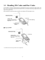
1.1 Reading 2D Codes and Bar Codes
Turn the BHT on, bring the reading window to a target 2D or bar code, and press the trigger switch. The
BHT turns the marker beam (laser) and illumination LED on to indicate the scanning range and scan the
target code, respectively.
When the BHT has read the code successfully, the indicator LED illuminates in blue.
Code scanning range
indicated by the marker
Power key
Indicator LED
Illuminates in blue when the
BHT has successfully read the
target code.
Trigger switch (M4 key)
Trigger switch
(M3 key)
Grip style BHT
Code scanning range
indicated by the marker
Power key
Indicator LED
Illuminates in blue when the
BHT has successfully read the
target code.
Trigger switch
(M5 key)
* For details about the scanning conditions, refer to Appendix A.
2
Chapter 1 Quick Guide
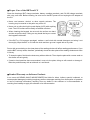
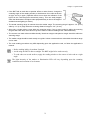
• If the BHT fails to read due to specular effects or other factors, change the
scanning angle of the reading window or the distance from codes as shown
at right, and try it again. (Specular effects occur when the reflection of the
light from the code becomes excessively strong. This can easily happen
when the illumination LED lights codes perpendicularly or due to the angle of
ambient intense lighting to codes.)
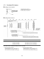
• The actual scanning range is narrower than the marker range. The scanning range is approx. 2.4" (6 cm)
wide by 1.6" (4 cm) high when the scanning distance is approx. 3.9" (10 cm).
• Allow only a single code to come within the scanning range. If two or more codes lie within the scanning
range at the same time, the scanner may fail to read or continue reading those codes alternately.
• The scanner can read codes omnidirectionally. Note that a target code plus its margin should lie within the
scanning range.
• The marker range should be used merely as a guide. It does not assure that a code within the marker range
can be read.
• The code reading procedure may differ depending upon the application used, so follow the application’s
manual.
• Before reading labels, clean them if stained.
• Avoid using the BHT in direct sunlight. The BHT might fail to read correctly.
• To read codes on curved surfaces, apply the reading window to the center of each code at a right
angle.
The light intensity of the marker or illumination LED will vary depending upon the scanning
conditions and variation of its elements.
3
1.2 Setting and Using the Hand Strap and
Stylus
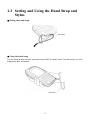
Setting the hand strap
Hand strap
Using the hand strap
Put your hand through the hand strap and hold the BHT as shown below. This will prevent you from
dropping the BHT accidentally.
Hand strap
4
Chapter 1 Quick Guide
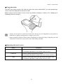
Using the stylus
The BHT has a touch screen LCD. With the stylus that comes with the BHT, you can operate keys,
menus, and icons displayed on the touch screen.
Before using the touch screen, be sure to set it up. (Refer to Chapter 2, Section 2.3.2, "Setting-up 2:
Calibrating the touch screen.")
• Always use the stylus to operate the touch screen. Do not use your fingernails or any pointed or
hard object or apply a strong pressure or impact to the LCD.
• Before operation, clean the surface of the LCD and the tip of the stylus if dirty. Using dirty ones will
scratch the LCD surface or prevent the stylus from sliding smoothly.
Operating the touch screen
Action
Tap
Description
Refers to touching the LCD once.
(Functionally equivalent to "click" with a mouse on a PC.)
Double-tap
Refers to quickly touching the LCD twice.
(Functionally equivalent to "double-click" with a mouse on a PC.)
Drag
Refers to moving the stylus to the object while touching the LCD.
(Functionally equivalent to "drag" with a mouse on a PC.)
5
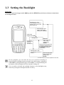
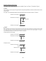
1.3 Setting the Backlight
30-key pad
Pressing the right-hand trigger switch (M4 key) with the SF/ALP key held down activates or deactivates
the frontlight function.
Backlight Off or Dim
(The backlight function is
Disable when you turn the
BHT power on.)
Press the right-hand
trigger switch while
holding down SF/ALP.
Right-hand
trigger switch (M4)
Backlight On
Press the
right-hand trigger
switch while
holding down
SF/ALP.
If no key is
pressed for 3
seconds.*
SF/ALP key
Press any key (except for the
simultaneous depression of
the right-hand trigger switch
and SF/ALP) or tap the
touch screen.
Backlight Off or Dim
(The backlight function is
Enable.)
Press the right-hand
trigger switch while
holding down
SF/ALP.
*For one minute if the BHT is placed on the CU.
In user programs, you can select the key to be used for activating or
deactivating the backlight function (instead of the initial setting: combination
of SF/ALP key and right-hand trigger switch (M4)), as well as modifying the
on-duration of the backlight before the automatic turning-off.
You can enable or disable the backlight function on the Backlight menu,
instead of pressing the backlight function on/off key.
6
Chapter 1 Quick Guide
26-key pad
Pressing the right-hand trigger switch (M4 key) with the SF key held down activates or deactivates the
frontlight function.
Backlight Off or Dim
(The backlight function is
Disable when you turn the
BHT power on.)
Press the right-hand
trigger switch while
holding down SF/ALP.
Right-hand
trigger switch (M4)
Backlight On
Press the
right-hand trigger
switch while
holding down
SF/ALP.
If no key is
pressed for 3
seconds.*
Press any key (except for the
simultaneous depression of
the right-hand trigger switch
and SF/ALP) or tap the
touch screen.
SF/ALP key
Backlight Off or Dim
(The backlight function is
Enable.)
Press the right-hand
trigger switch while
holding down
SF/ALP.
*For one minute if the BHT is placed on the CU.
In user programs, you can select the key to be used for activating or deactivating the frontlight
function (instead of the initial setting: combination of SF key and right-hand trigger switch (M4)), as
well as modifying the ON-duration of the frontlight before the automatic turning-off.
You can enable or disable the frontlight function on the Frontlight menu, instead of pressing the
frontlight function on/off key.
7
1.4 Using the Keypad
Entering Numerical Data
To enter numerical data, use the numerical keys and the ENT key.
For example, to enter the number "120," press the 1, 2 and 0 keys and then press the ENT key.
If you type in any wrong value, press the C/BS (BS) key and then enter the correct one.
Entering alphabetic characters
The alphabet entry procedure differs depending upon the keypad type.
30-key pad
Holding down the SF/ALP key only for the specified period (1.5 seconds) or more switches the BHT to
the alphabet entry mode. You can use the numeric keys and function keys to type in alphabet letters
printed on those keys in light blue. To switch back to the numeric entry mode, hold down the SF/ALP key
again.
26-key pad
Pressing the ALP key switches the BHT to the alphabet entry mode. You can type in alphabet letters
using the numeric keys in the same way as you use a cellular phone. If you press a numeric key, the
alphabet assigned to that key will appear in the ALP window (see Chapter 2, Section 2.2.2 "Status
Indicators on the LCD." Pressing the ENT key establishes the alphabet displayed. To switch back to the
numeric entry mode, press the ALP key again.
For both the 30-key and 26-key pad types, you can switch between the numeric and alphabet entry
modes also in user programs. For programming the mode switching, refer to the "BHT-200 API
Reference Manual."
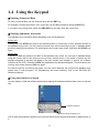
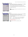
Using the software keyboard
You can display or hide the software keyboard by tapping the software keyboard status icon on the task
tray.
Software keyboard
Software keyboard status icon
Just as from the hardware keyboard, you can enter data from the software keyboard, by tapping keys on
it.
8
Chapter 1 Quick Guide
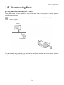
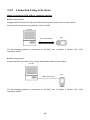
1.5 Transferring Data
Using radio link (BHT-202QW-CE only)
Using radio waves, the BHT-202QW-CE may transfer data to an access point in a spread spectrum
communications system.
If there are too many communications errors, first make sure that the BHT-202QW-CE points directly
at an access point.
Host PC
Access point
Built-in antenna
For data transfer using radio link, it is necessary to configure a wireless local area network (wireless
LAN) connecting the BHT-202QW-CE and access points.
9
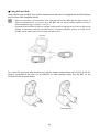
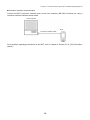
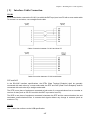
Using infrared link
Using infrared rays, the BHT may transfer data directly to the host PC equipped with an IrDA interface
port and other IrDA-compliant devices.
• Make sure that there is no obstruction in the light path between the BHT and any target stations. In
infrared communication, you need to keep the BHT and any target stations within the effective
infrared radiation range, usually 15 cm (5.9").
• Shield the IrDA interface from direct sunlight, ambient intense lighting (inverter-driven fluorescent
lighting, in particular), and other potential sources of infrared radiation. Sources to watch out for
include remote control units for television sets and the like.
Host PC
BHT
BHT
For a host PC having no IrDA interface port, use the optical communication unit CU-201 or CU-221
(option) connected to the host via an RS-232C or USB interface cable. Put the BHT on the
CU-201/CU-221 as shown below.
Grip style BHT
10
Chapter 2
Getting Started the BHT
and System Menu
This chapter summarizes the BHT system configuration and describes the operation including
preparation and System Menu (which is required for the efficient use of application programs).
2.1
BHT System Configuration .............................................................................................................................12
2.2
Components ...................................................................................................................................................16
2.2.1
Names and Functions ..............................................................................................................................16
2.2.2
Status Indicators on the LCD ...................................................................................................................20
2.2.3
Notes for Using the BHT ..........................................................................................................................22
2.3
Preparation .....................................................................................................................................................23
2.3.1
Setting-up 1: Loading the battery cartridge..............................................................................................23
2.3.2
Setting-up 2: Calibrating the touch screen...............................................................................................28
2.3.3
Battery Replacement Notes .....................................................................................................................29
2.3.4
BHT Turning-off Notes .............................................................................................................................30
[1]
[2]
2.3.5
2.4
"Shutdown in progress" message .......................................................................................................30
Backing up the Registry ......................................................................................................................31
Warm and Cold Booting...........................................................................................................................32
Replacement of the Backup Battery ...............................................................................................................34
2.4.1
Replacing the Backup Battery..................................................................................................................35
2.4.2
Resetting the Discharge Counter.............................................................................................................41
2.5
Operating in System Menu .............................................................................................................................42
2.5.1
Desktop....................................................................................................................................................42
2.5.2
Start Menu................................................................................................................................................46
2.5.3
Operating in System Menu ......................................................................................................................57
2.5.4
Detailed Description of the Functions in System Menu ...........................................................................60
2.6
[1]
Execute Program ................................................................................................................................60
[2]
Communication Menu .........................................................................................................................61
[3]
System Properties Menu.....................................................................................................................74
[4]
Test Menu............................................................................................................................................96
[5]
Explorer.............................................................................................................................................109
[6]
System Information ...........................................................................................................................109
Wireless Zero Configuration (WZC) .............................................................................................................110
11
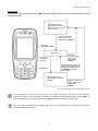
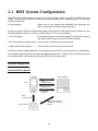
2.1 BHT System Configuration
The BHT barcode data collection system requires the following hardware as well as the BHT Bar Code
Handy Terminal (which reads bar codes and accepts keypad entry), depending upon the intended
system configuration.
• Host computer:
Allows you to edit, manage and download user programs and
data, as well as downloading system programs.
For host computers having no IrDA interface ports, the optional CU-200 optical communication unit and
RS-232C interface cable (for CU-201) or USB cable (for CU-221) are available.
• CU-200 (option):
Exchanges programs and data with the BHT via the IrDA interface
and with the host computer via the RS-232C interface.
• RS-232C interface cable (option): Connects the CU-200 and the host computer.
• USB interface cable (option):
Connects the CU-221 and the host computer.
Connector interface cable/USB cable connection between the BHT and host computer is also possible.
As an application development tool, Microsoft eMbedded Visual C++ (Service Pack 4 or later), Microsoft
Visual Studio .NET or Microsoft Visual Studio .NET 2003 should be used.
System Configuration
Communications System
Host computer
BHT
IrDA
communication
USB interface
Connector
interface
IrDA
communication
CU-200 (option)
RS-232C (CU-201) or
USB (CU-221) interface
(option)
12
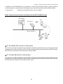
Chapter 2 Getting Started the BHT and System Menu
In addition, the BHT-202QW-CE may operate in a radio communications system (spread spectrum
communication) by connecting with access points by a wireless local area network (wireless LAN).
• Access point:
Wireless communications base unit for the BHT
Radio Communications System (available with the BHT-202QW-CE only)
Host computer
BHT
Access point
Roaming
function
Ethernet 10BASE-T
BHT
Access
point
CU-201 and RS-232C Interface Cable (option)
The CU-201 is an IrDA-compliant communications unit which is required when your host computer is not
equipped with an IrDA interface port. The CU-200 exchanges data and programs with the BHT optically,
and with the host computer via the RS-232C interface cable.
CU-221 and USB Interface Cable (option)
The CU-221 is an IrDA-compliant communications unit and is required when the host computer is not
equipped with an IrDA interface port. The CU-200 exchanges data and programs with the BHT optically,
and with the host computer via the USB interface cable.
13
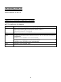
BHT Operating System (OS)
Microsoft Windows CE .NET 5.0
Application Program Development Environment
PC for application development
Item
Description
OS
Microsoft Windows 2000 Professional Service Pack 2 or later,
Microsoft Windows 2000 Server Service Pack 2 or later, or
Microsoft Windows XP Professional
CPU
Pentium-II class processor, 450 MHz or faster
RAM
For Microsoft Windows 2000 Professional Service Pack 2 or Microsoft Windows XP
Professional:
96 MB or more (128 MB or more recommended)
For Microsoft Windows 2000 Server Service Pack 2:
192 MB or more (256 MB or more recommended)
HDD
200 MB or more hard disk space
Display
Monitor with 800 x 600 resolution or larger
14
Chapter 2 Getting Started the BHT and System Menu
Application Development Tool
Microsoft eMbedded Visual C++ 4.0 Service Pack 4 or later, Microsoft Visual Studio .NET or Microsoft
Visual Studio .NET 2003
You can download Microsoft eMbedded Visual Tools 4.0 and Service Pack 4 from the Microsoft Web site
at:
(Microsoft eMbedded Visual C++ 4.0)
http://www.microsoft.com/downloads/details.aspx?displaylang=en&FamilyID=1dacdb3d-50d1-41b2a107-fa75ae960856
(Service Pack 4)
http://www.microsoft.com/downloads/details.aspx?displaylang=en&FamilyID=4A4ED1F4-91D3-4DB
E-986E-A812984318E5
APIs available for application development tools are:
- Win32API
- Microsoft Foundation Class (MFC)
- Dedicated APIs (for device control or data entry from the BHT)
When using Microsoft Visual Studio .NET or Microsoft Visual Studio .NET 2003, refer to the
“BHT-200-CE Class Library Reference Manual.”
Software Development Kit
BHT-200 Software Development Kit named "BHT202Q_XXXXXX.msi" (XXXXXX: version)
- This is a library to be embedded into application development tools for developing applications for the
BHT-202QW-CE.
- For details about the BHT-200 Software Development Kit, refer to the "BHT-200-CE API Reference
Manual" or "BHT-200-CE Class Library Reference Manual."
15
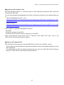
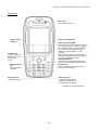
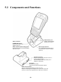
2.2 Components
2.2.1
Names and Functions
* Provided on the BHT-202QW-CE
Synchronization LED*
Flashes during wireless
communication.
Indicator LED
Illuminates in blue when the BHT has successfully read a 2D code or bar code.
Charge LED
Illuminates in red during charging and turns green at
completion of charging.
Built-in antenna*
Do not cover this
antenna section
with metalevaporated tape
or by hand.
Doing so may
result in
communications
failures.
Touch screen LCD (liquid crystal display)
Shows the characters and graphic patterns.
You may directly tap the screen with the
stylus for data entry.
Trigger switch (M4 key)
Press this switch to start code
reading.
Interface port:
USB interface port
and connector
interface port
Trigger switch (M3 key)
Press this switch to start code
reading.
Hand strap
Be sure to put your
hand through this strap
to prevent you from
dropping the BHT
accidentally.
Reset button
IrDA interface port
Used to exchange data/programs with Charge terminals
the host computer via its integrated IR
port or via the optical communication
unit CU-200.
Reading window
Hand belt
Compact Flash card slot
Insert an optional Compact Flash
card into this memory extension
slot.
Rechargeable battery
cartridge
Main power source of the
BHT.
Release button
Stylus
Release button
Slide this button to open the
battery cartridge cover.
Battery cartridge cover
Remove this cover to replace the
battery cartridge.
16
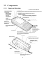
Chapter 2 Getting Started the BHT and System Menu
Grip style BHT
Trigger switch (M5 key)
Press this switch to start code
reading.
17
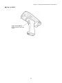
The functions of the keys may be set by user programs. Shown below is a set of sample functions.
30-key pad
Power key
Turns the BHT on or off.
Trigger switch (M3 key)
Trigger switch (M4 key)
C (Clear)/
BS (Backspace) key
Moves back one
character.
Pressing this key with
the SF key held down in
BhtShell returns to the
previous screen.
SF (Shift)/ALP (Alphabet) key
Used in combination with numerical keys
for special input procedures.
Holding down this key for 1.5 seconds or
more switches between the numeric
entry and alphabet entry modes.
Magic keys [M1] to [M5]*
These keys may be used as an SF key,
ENT key, CTRL key, ALT key, TAB key,
CLEAR key, backlight function on/off
key, Marker key, or trigger switch
depending upon definition in System
Menu or in user programs.
Although [M3] to [M5]* are set as trigger
switches by default, user-defined virtual
key codes can be assigned to them.
ENT (Enter) key
Finalizes the inputted data or
operations, and starts the
corresponding processing.
Numerical keys
Used for data input.
* Provided on the Grip style BHT
18
Chapter 2 Getting Started the BHT and System Menu
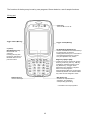
26-key pad
Power key
Turns the BHT on or off.
Trigger switch
(M3 key)
Trigger switch (M4 key)
Magic keys [M1] to [M5]*
These keys may be used as an SF key, ENT
key, CTRL key, ALT key, TAB key, CLEAR
key, backlight function on/off key, Marker
key, or trigger switch depending upon
definition in System Menu or in user
programs.
Although [M3] to [M5]* are set as trigger
switches by default, user-defined virtual key
codes can be assigned to them.
ALP (Alphabet) key
Pressing this key switches between the
numeric entry and alphabet entry modes.
C (Clear) key
Pressing this key in
BhtShell returns to
the previous
screen.
BS (Backspace)
key
Moves back one
character.
SF (Shift) key
Used in combination with other keys for
special input procedures.
ENT (Enter) key
Finalizes the input data or
operations, and starts the
corresponding processing.
Numerical keys
Used for data input.
* Provided on the Grip style BHT
19
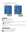
2.2.2
Status Indicators on the LCD
Windows desktop
on 30-key pad type
Windows desktop
on 26-key pad type
Status indicators
Status indicators
Battery voltage level
Shows the current battery voltage level.
Displays when the voltage level is high.
Displays when the voltage level is low.
The grip style BHT shows two icons as shown below. The upper one is for the battery cartridge loaded in
the BHT body and the lower one for that in the grip.
(Voltage level in the BHT body)
(Voltage level in the grip)
The displayed battery level shows the terminal voltage of the battery cartridge, not how much power is
left.
The battery voltage level varies depending upon the operation of the BHT, so the displayed level also
may vary.
Software keyboard display/hide
Shows whether the software keyboard is displayed or hidden.
(Tapping this icon toggles the software keyboard on and off.)
Displays when the software keyboard is displayed.
Displays when the software keyboard is hidden.
20
Chapter 2 Getting Started the BHT and System Menu
Synchronization state (Provided on the BHT-202QW-CE)
Displays the open state of the wireless device and the radio field intensity.
Displays when the wireless device is open.
Shows the radio field intensity with the number of bars.
The radio field intensity icons ( ,
, and
) indicate that the radio link is established but do not
assure you that there will be few communications errors.
Wireless Zero Configuration (Provided on the BHT-202QW-CE)
Indicates that the Wireless Zero Configuration (WZC) radio is connected to a wireless network.
Indicates that the Wireless Zero Configuration (WZC) radio is not connected to a wireless network.
Keypad shift state
Displays when the keypad is shifted.
ActiveSync
Displays when the BHT is linked with the PC via the IrDA, USB or etc. interface using Microsoft
ActiveSync.
Alphabet input state
Displays when the alphabet input function is activated.
(Pressing the SF/ALP (ALP) key switches between the numeric entry and alphabet entry modes.)
The ALP window appears only on the 26-key pad type when the alphabet input function is
activated. Pressing any numeric key displays the alphabet letter assigned to that key in this ALP
window.
Desktop display
Tapping this icon when an application program is running switches the screen to the desktop
display. Tapping it again returns to the application execution screen.
Standby state
Appears when the CPU comes to be on standby.
(This icon does not appear by default. To display it, you need to change the setting in System
Menu or in user programs. For the setting procedure in System Menu, refer to Section 2.5.4, "[3.7]
Status Display." For that in user programs, refer to the "BHT-200-CE API Reference Manual" or
"BHT-200-CE Class Library Reference Manual."
Caps Lock state
Appears when the Caps Lock switch is pressed on the software keyboard.
21
2.2.3
Notes for Using the BHT
Windows desktop on the LCD
The Windows desktop shown in this manual may be a little different from that in the actual screens on
the LCD.
(Windows desktop sample)
This task tray also may be a little different from that in the
actual screen.
No refreshing of the LCD screen when on standby
To minimize the power consumption, the BHT automatically switches to the standby mode after it has not
been operated for the specified period*.
In the standby mode, the LCD is not refreshed so that icons on the task bar and task tray may not be
displayed or refreshed or that the calendar clock may not show the correct date or time.
* The default is one second. The period can be changed in user programs. For details, refer to the
"BHT-200-CE API Reference Manual" or "BHT-200-CE Class Library Reference Manual."
Opening the wireless communications device
To minimize the power consumption, the wireless communications device in the BHT is not working in
regular operation.
To make the BHT ready for wireless communication, you need to open the wireless communications
device with the RF Open/Close switches in System Menu or by coding in user programs.
For the opening/closing procedure with the RF Open/Close switches in System Menu, refer to Section
2.5.4, "[3.8] Radio Frequency, Displaying the wireless module version and opening/closing the RF
device."
For coding in user programs, refer to the "BHT-200-CE API Reference Manual" or "BHT-200-CE Class
Library Reference Manual."
22
Chapter 2 Getting Started the BHT and System Menu
2.3 Preparation
2.3.1
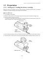
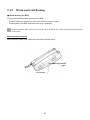
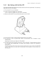
Setting-up 1: Loading the battery cartridge
Before the first use of the BHT, be sure to load the battery cartridge as shown below. The battery
cartridge is not loaded in the BHT when shipped from the factory.
Into the BHT body
(1) Turn the BHT upside down.
(2) Slide the release buttons in the direction shown below and remove the battery cartridge cover.
(3) Push the battery cartridge into the BHT.
(To remove it, first make sure that the BHT is turned off. Slide the release buttons, remove the
battery cartridge cover, and pull up the battery pull strap.)
Release button
Battery
cartridge
cover
Release
button
Battery pull strap
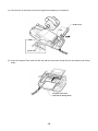
(4) Set the battery cartridge cover back into place and slide the release buttons to the original position.
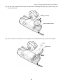
(5) Place the BHT on the CU-200 to charge the rechargeable battery cartridge. (Refer to Section 5.5.)
Battery
cartridge
Battery pull strap
23
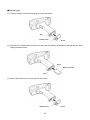
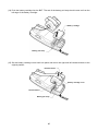
Into the grip
(1) Take the bottom cover off the grip by removing the screw.
Grip
Bottom cover
Screw
(2) Pull the lock in the direction of the arrow and insert the battery cartridge into the grip with the boss
facing as shown below.
Boss
Battery cartridge
Lock
(3) Secure the bottom cover to the grip with the screw.
Bottom cover
24
Screw
Chapter 2 Getting Started the BHT and System Menu
• Never disassemble or heat the battery cartridge, nor put it into fire or water; doing so
could cause battery-rupture or leakage of battery fluid, resulting in a fire or bodily injury.
• Do not carry or store the battery cartridge together with metallic ball-point pens,
necklaces, coins, hairpins, etc.
Doing so could short-circuit the terminal pins, causing the batteries to rupture or the
battery fluid to leak, resulting in a fire or bodily injury.
• Avoid dropping the battery cartridge or letting it undergo any shock or impact.
Doing so could cause the batteries to break, generate heat, rupture or burn.
• Never charge the rechargeable battery cartridge where any inflammable gases may be
emitted; doing so could cause fire.
• Do not use batteries or power sources other than the specified ones; doing so could
generate heat or cause malfunction.
• The BHT has an integrated backup power source which backs up the memory and calendar clock in
the BHT when no battery cartridge is loaded or the voltage level of the battery cartridge drops
below the specified level. The backup power source is automatically charged by the battery
cartridge.
When you first load the battery cartridge after purchase or you load it after leaving the BHT unused
for a long time, do not remove the battery cartridge for approx. 48 hours after that loading. This is
for charging the memory backup source integrated in the BHT.
• Avoid storing the rechargeable battery cartridge in a hot place (50°C, 122°F or higher). The battery
capacity may be decreased.
• Do not touch the charge terminals of the rechargeable battery cartridge or stain those terminals.
Doing so could result in a charging failure.
25
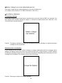
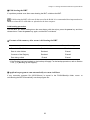
Battery Voltage Level on the Status Indicator Line
The battery voltage level is always displayed on the status indicator line.
(For details, refer to Section 2.2.2 "Status Indicators on the LCD.")
Low Battery Indication
Low battery warning
If the battery output voltage drops below a specified lower level limit when the BHT is in operation, the
BHT displays the following message for approx. 2 seconds and beeps three times. After that, it will
resume previous regular operation.
Solution: The battery cartridge will need to be recharged before long. Recharge or replace the battery
cartridge as soon as possible.
Shutdown due to low battery
If you continue to use the BHT without recharge or battery replacement after the message above
appears, the battery output level lowers to the extent the BHT can no longer operate. The BHT displays
the following message, beeps five times, and then turns itself off. Depending upon the battery level, the
message may not appear or the beeper may not sound five times.
Solution: Recharge or replace the battery cartridge.
26
Chapter 2 Getting Started the BHT and System Menu
Grip style BHT
As long as the voltage level of either one of battery cartridges loaded in the BHT body and grip is higher
than the specified level, no low battery messages will appear. If any low battery message appears,
therefore, you need to replace both battery cartridges. Even if you only have one fully-charged
replacement battery cartridge on hand, remove both batteries.
• You may charge the rechargeable battery cartridge with the optional CU-200 communication unit
or optional CH-201 charger. For the charging procedure using the CU-200, refer to Chapter 5. For
that using the CH-201, refer to the "CH-201 User's Manual."
• If the "Charge the battery!" message appears after the BHT undergoes any shock or impact, turn the
power off and on and then check the battery output level. The battery may not have run out.
• Only use the dedicated charger (CU-200 or CH-201) for charging the rechargeable
battery cartridge.
Using a different type of charger could cause battery-rupture or leakage of battery fluid
and result in a fire, bodily injury, or serious damage to property.
• Never charge a wet or damp rechargeable battery cartridge.
Doing so could cause the batteries to break, generate heat, rupture or burn.
27
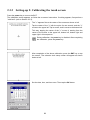
2.3.2
Setting-up 2: Calibrating the touch screen
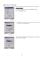
Press the power key to turn on the BHT.
The calibration screen appears, so follow the on-screen instructions. If nothing appears, first perform a
"cold boot" (refer to Section 2.3.5).
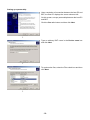
The "+" appears first at the center of the screen as shown at left.
Tap the center of the "+" with the stylus for one second, and the "+"
moves to the upper left. Tap its center, and it moves to the bottom left.
This way, tapping the center of the "+" moves it, starting from the
center of the screen to the upper left, bottom left, bottom right and
upper right in this sequence.
During calibration, the power key is disabled. After completing
the calibration, press the power key.
⇓
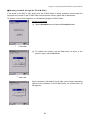
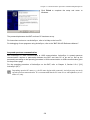
After completion of the above calibration, press the ENT key or tap
the screen. The calendar clock setup screen will appear as shown
below at left.
⇓
Set the date, time, and time zone. Then tap the OK button.
28
Chapter 2 Getting Started the BHT and System Menu
2.3.3
Battery Replacement Notes
When is battery replacement needed?
If the "Charge the battery!" appears on the LCD, replace the battery cartridge with a fully charged one.
If you leave the BHT without replacing the battery cartridge, then the integrated calendar clock or data
will no longer be backed up so that the calendar clock may stop or the data may be lost.
Grip style BHT
If "Charge the battery!" appears on the LCD when battery cartridges are loaded in both the BHT body
and grip, replace both battery cartridges. (As long as the voltage level of either one of battery cartridges
is higher than the specified level, this warning message will not appear.) Always remove both battery
cartridges, even if you only have one fully-charged replacement battery cartridge on hand.
• Replace the battery cartridge quickly.
• Be sure to turn the BHT off before battery replacement.
• Load a charged battery cartridge within 3 minutes after the removal to avoid data loss.
• After battery replacement, turn the BHT on and check its operation.
• If you leave the BHT with no battery cartridge loaded for a long time, the contents of the memory
may no longer be backed up so that the data stored in the BHT may be lost. It is recommended that
important data be saved into the FLASH folder or uploaded to the host computer.
• The battery cartridge will gradually deteriorate during the repeated cycles of charging and
discharging due to its properties. When the battery operation period becomes shortened due to its
deterioration even if it has been charged for the specified hours, replace the battery cartridge with a
new one.
• Use only DENSO WAVE-authorized battery cartridges and chargers.
• Never dispose of battery cartridges into a fire. They should be recycled properly. Do not throw them
in a trash.
• When disposing of the battery cartridge, cover the terminal pins with vinyl tape to prevent
short-circuit.
29
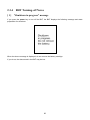
2.3.4
BHT Turning-off Notes
[ 1 ] "Shutdown in progress" message
If you press the power key to turn off the BHT, the BHT displays the following message and starts
preparation for shutdown.
When the above message is displayed, do not remove the battery cartridge.
If you do so, the data stored in the BHT may be lost.
30
Chapter 2 Getting Started the BHT and System Menu
[ 2 ] Backing up the Registry
The Registry is the part of Windows CE that stores setup information required for operating the BHT.
Backing-up the Registry
When the BHT is on, pressing the power key with the SF/ALP (SF) key held down displays the screen
shown at right and starts backing up the Registry.
Do not remove the battery cartridge until the backup operation is completed and the message
disappears.
Restoring the Registry
If the Registry is lost, the OS automatically restores it.
If the OS fails to restore it (since the Registry has not been backed up), the following error message
appears.
To make the Registry revert to the default, initialize the memory including the Registry. Refer to Section
2.5.4, "[3.4] File System, Initializing the memory including the Registry."
31
2.3.5
Warm and Cold Booting
Warm-booting the BHT
In any of the following cases, warm-boot the BHT:
- The BHT makes no response to entry from the touch screen or keys.
- The programs in the BHT malfunction due to any problems.
Warm-booting the BHT will not erase data stored in the RAM, but it will erase data being edited and
not be saved.
Warm booting procedure
When the BHT power is on, press the reset button with the stylus.
Stylus
Reset button
32
Chapter 2 Getting Started the BHT and System Menu
Cold-booting the BHT
If a problem persists even after warm-booting the BHT, cold-boot the BHT.
Cold-booting the BHT will erase all data stored in the RAM. It is recommended that important data be
saved into the FLASH folder or uploaded to the host computer.
Cold booting procedure
Turn the BHT off. While holding down the reset button with the stylus, press the power key and then
release them. Press the power key again, and the BHT cold-boots.
Contents of the memory after warm-/cold-booting the BHT
After warm booting
After cold booting
Data in the FLASH folder
Retained
Retained
Data in other folders
Retained
Erased
Contents of the Registry
Retained
Erased*
Erased
Erased
Data being edited
* If the Registry has been backed up, the backup will apply. For the backup procedure, refer to Section
2.3.4, "[ 2 ] Backing up the Registry."
Application program to run automatically at warm-/cold-boot
If any execution program file (XXXXXX.exe) is stored in the FLASH\StartUp folder, warm- or
cold-booting the BHT automatically runs that program file.
33
2.4 Replacement of the Backup Battery
If the following warning message appears on the LCD, you need to replace the backup battery (refer to
Section 2.4.1).
If you remove the backup battery, the contents of the memory may no longer be backed up so that the
data stored in the BHT may be lost. It is recommended that important data be saved into the FLASH
folder or uploaded to the host computer.
This warning message appears each time the backup battery is fully discharged after 200 times of full
discharges.
Even if this warning message appears, you can continue operation by tapping the OK button in the top
right corner of the message window.
Each time the backup battery is fully discharged, the internal discharge counter automatically
increments by one; however, replacing the backup battery does not reset the counter to zero
automatically. You need to reset the discharge counter (refer to Section 2.4.2).
When the BHT is shipped from the factory, the discharge counter is reset to zero.
34
Chapter 2 Getting Started the BHT and System Menu
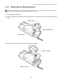
2.4.1
Replacing the Backup Battery
Before proceeding to the replacement procedure below, it is recommended that you save important
data into the FLASH folder or upload it to the host computer.
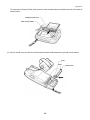
(1) Turn the BHT upside down.
(2) Slide the right and left release buttons in the direction of the arrows to remove the battery cartridge
cover.
Release button
Battery cartridge cover
Release button
(3) Pull up the battery pull strap to remove the battery cartridge.
Battery cartridge
Battery pull strap
35
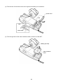
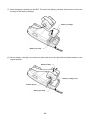
(4) Pull the lock of the inside cover to the right and towards you to release it.
Inside cover
Lock
Lock
Inside cover
(5) Pull the right end of the clear insulation sheet up and out of the BHT.
Battery pull strap
Clear insulation
sheet
36
Chapter 2 Getting Started the BHT and System Menu
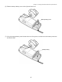
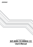
(6) Slide the backup battery cover to the right and take it out.
Backup battery cover
(7) Lift up the backup battery, take its lead wires out of the groove, and disconnect the battery connector
as shown below.
Backup battery
37
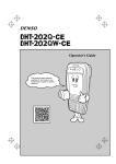
(8) Connect the connector of a new backup battery with the red lead facing to the left.
(9) Route the lead wires inside the guides through the groove. For easier routing, use a tool whose tip is
thin and round.
(10) Load the backup battery.
Backup battery
Red lead
Black lead
Guides
Groove
Backup battery
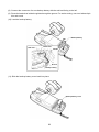
(11) Slide the backup battery cover back into place.
Backup battery cover
38
Chapter 2 Getting Started the BHT and System Menu
(12) Set the clear insulation sheet back into place while threading the battery pull strap through the
cutout in the sheet.
Battery pull strap
Clear insulation sheet
(13) Set the inside cover so that its lock and pawl become fitted between the printed circuit boards.
Lock
Pawl
Inside cover
39
(14) Push the battery cartridge into the BHT. The end of the battery pull strap should come out from the
left edge of the battery cartridge.
Battery cartridge
Battery pull strap
(15) Set the battery cartridge cover back into place and return the right and left release buttons to the
original position.
Release button
Battery cartridge cover
Release button
Battery pull strap
40
Chapter 2 Getting Started the BHT and System Menu
2.4.2
Resetting the Discharge Counter
If you replace the backup battery, reset the internal discharge counter in the BhtShell System Properties
Menu. For detailed operation, refer to Section 2.5.4, "[3] System Properties Menu,
Backup Battery Discharge Counter."
41
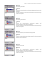
2.5 Operating in System Menu
2.5.1
Desktop
Upon completion of setting-up 2 (described in Section 2.3.2), the desktop appears on the touch screen
as shown below.
Double-tapping icons on the desktop runs the corresponding programs.
My Device
On the desktop, double-tap My Device. The screen shown at left
appears.
With this program, you can browse the file information in the BHT.
42
Chapter 2 Getting Started the BHT and System Menu
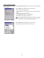
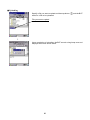
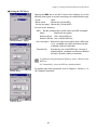
Recycle Bin
On the desktop, double-tap Recycle Bin. The Recycle Bin opens.
The Recycle Bin stores files you deleted in the BHT.
To retrieve files stored in the Recycle Bin, select the file to be
retrieved and choose File|Restore.
To delete a file(s) in the Recycle Bin from the BHT memory
permanently, select the file(s) to be deleted and choose File|Delete.
To delete all files in the Recycle Bin, choose File|Empty Recycle
Bin.
If you delete files in the FLASH folder, they will not be stored in
the Recycle Bin but deleted from the memory immediately.
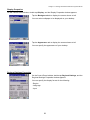
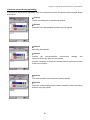
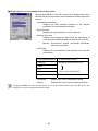
BhtShell
On the desktop, double-tap BhtShell. The System Menu screen
shown at left appears.
For details about this program, refer to Section 2.5.3, "Operating in
System Menu."
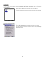
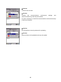
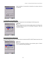
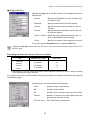
Internet Explorer
On the desktop, double-tap Internet Explorer. The screen shown at
left appears.
With this program, you can browse Web pages.
Before running Internet Explorer, you need to make RF-related
settings and open the wireless communications device. For
details, refer to Section 2.5.4, "[3.8] Radio Frequency."
43
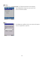
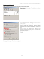
Configuring Proxy Server
When the Internet Explorer runs, choose View|Internet Options to
call up the Options window.
Tap the Connection tab to display the screen shown at left. Make
your settings.
Messenger
On the desktop, double-tap Messenger. The screen shown at left
appears.
Microsoft WordPad
On the desktop, double-tap Microsoft WordPad. The screen shown
at left appears.
44
Chapter 2 Getting Started the BHT and System Menu
My Documents
On the desktop, double-tap My Documents. The screen shown at left
appears.
With this program, you can browse the file information in the BHT.
Remote Desktop Connection
On the desktop, double-tap Remote Desktop Connection. The
screen shown at left appears.
45
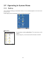
2.5.2
Start Menu
Tap the
button in the bottom left corner of the desktop.
The Start menu appears where you can run programs and make
system settings.
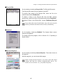
Terminal
On the Start menu, tap Programs|Communication|Terminal.
The screen shown at left appears. You can create a new session.
Internet Explorer
On the Start menu, tap Programs|Internet Explorer to run Internet Explorer.
For details, refer to Section 2.5.1, "Desk Top,
Internet Explorer."
Windows Explorer
On the Start menu, tap Programs|Windows Explorer to run Windows Explorer.
For details, refer to Section 2.5.1, "Desk Top,
My Device."
46
Chapter 2 Getting Started the BHT and System Menu
Command Prompt
On the Start menu, tap Programs|Command Prompt.
The screen shown at left appears.
Favorites
On the Start menu, tap Favorites.
Your Favorites list appears.
To add items to your Favorites list, create a shortcut(s) of the desired file(s) in the \Windows\favorites
folder.
Documents
On the Start menu, tap Documents.
Recently opened documents appear.
To add files to the Start menu, use the standard API "SHAddToRecentDocs(). For details about
SHAddToRecentDocs(), refer to the Help of application development tools.
Control Panel
On the Start menu, tap Settings|Control Panel.
The screen shown at left appears.
You can configure the basic Windows operating environments in your
BHT.
47
Backlight Properties
On the Control Panel window, double-tap Backlight, and the Backlight Properties window appears.
- Backlight function(*1)
Enable or disable the backlight function. If it is enabled, the backlight
comes on when you press any key or tap the touch screen.
- Backlight On-duration
Set the ON-duration of the backlight that comes on when you press
any key or tap the touch screen.
Battery Power: ON-duration when the BHT is not placed on the CU.
External Power: ON-duration when the BHT is placed on the CU.
- Brightness Level
Select the desired brightness level from the following four choices:
Off
Low Bright
Mid Bright
High Bright
(Dark)
↑
|
|
↓
(Bright)
- Power Save Mode
Change the settings for turning off the backlight after the BHT has not
been used for a specified period of time.
Off:
The backlight turns off immediately.
Dim:
The backlight remains on very dimly.
(*1)
Pressing the backlight function on/off key (the initial setting: the
simultaneous depression of the SF key and right-hand trigger
switch (M4 key)) toggles between enabled and disabled states,
regardless of the backlight function setting made on this screen.
48
Chapter 2 Getting Started the BHT and System Menu
BHTSettings
On the Control Panel window, double-tap BHTSettings, and the
BHTSettings window appears.
For details, refer to Section 2.5.4. [3] “System Properties Menu."
System Properties
On the Control Panel window, double-tap System, and the System Properties window appears.
Tap the General tab to display the screen shown at left.
Choose the Memory tab to display the screen shown at left.
You can check the memory allocation and the free space of the RAM.
You can also change the memory allocation by moving the slider.
According to your operating requirements, assign the memory
between "Storage memory" and "Program memory."
Depending upon the memory allocation (e.g., insufficient
program execution space), the BHT might not operate normally.
49
Stylus Properties
On the Control Panel window, double-tap Stylus, and the Stylus
Properties window appears.
You can adjust the double-tap speed.
Tap the Calibration tab to display the window shown at left.
Tab the Recalibrate to display the screen shown at left.
Follow the on-screen instructions. Refer to Section 2.3.2 "Setting-up
2: Calibrating the touch screen."
50
Chapter 2 Getting Started the BHT and System Menu
Dialing Properties
On the Control Panel window, double-tap Dialing, and the Dialing
Properties window appears.
You can set up the telephone line.
Owner Properties
On the Control Panel window, double-tap Owner, and the Owner Properties window appears.
Tap the Network ID tab to display the window shown at left.
You can specify a user name, password and domain required to
access the network resource.
51
Volume & Sounds Properties
On the Control Panel window, double-tap Volume & Sounds, and the Volume & Sounds properties
window appears.
Tap the Volume tab to display the screen shown at left.
You can make the following settings:
- Adjust the beeper volume except volumes for key entry and screen
taps
- Enable/disable the beeper for events
- Enable/disable the beeper driven by programs
- Enable/disable the beeper for notification
You may adjust the beeper volume to six levels (0 to 5) on this
screen; however, four levels are available in practice since levels
1 and 2 and levels 3 and 4 produce the same volume.
Tap the Sounds tab to display the screen shown at left.
You can configure beeper sounds for various events.
52
Chapter 2 Getting Started the BHT and System Menu
Display Properties
On the Control Panel window, double-tap Display, and the Display Properties window appears.
Tap the Background tab to display the screen shown at left.
You can select wallpaper to be displayed on your desktop.
Tap the Appearance tab to display the screen shown at left.
You can specify the appearance of your desktop.
Regional Settings Properties
On the Control Panel window, double-tap Regional Settings, and the
Regional Settings Properties window appears.
You can specify the display format for the following:
- Region
- Language
- Input
53
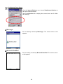
Connection
On the Control Panel window, double-tap Network and Dial-up Connection, and the Connection
window appears.
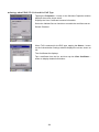
Double-tap the "Make New Connection" icon starts Wizard.
Follow the Wizard instructions and set the connection name and type.
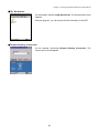
PC Connection Properties
Tap the PC Connection tab to display the screen shown at left.
You can change the connection method to the PC. Tap the Change
Connection button.
54
Chapter 2 Getting Started the BHT and System Menu
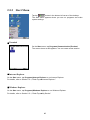
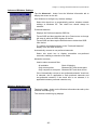
Date/Time Properties
On the Control Panel window, double-tap Date/Time, and the
Date/Time Properties window appears.
You can specify the date, time and time zone.
The entry range to the year is 2003 to 2099.
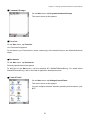
Input Panel Properties
On the Control Panel window, double-tap Input Panel, and the Input
Panel Properties window appears.
Tap the Options button to display the screen shown at left.
You can switch the input panel (software keyboard) between large
and small keys.
Regardless of the setting made for "Use gestures for...," the
gestures* are always active.
* The Gesture refers to special stylus operations that enable
special input on the software keyboard as shown at left.
55
Taskbar
On the Start menu, tap Settings|Taskbar. The Taskbar and Start Menu window appears.
Tap the General tab to display the screen shown at left.
You can customize the taskbar.
Run
On the Start menu, tap Run, and the screen shown at left appears.
You can run applications or open files.
56
Chapter 2 Getting Started the BHT and System Menu
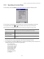
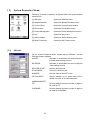
2.5.3
Operating in System Menu
On the desktop, double-tap BhtShell. System Menu starts up to display the following screen:
To run the items in System Menu, tap the desired item or press the corresponding numerical key.
To quit System Menu, tap the
or
button located in the top right corner of the window.
The keys below are so designed that the function of each key is consistent in every screen.
Numerical keys
Pressing a numerical key corresponding with a desired menu
number starts the desired item displayed on the screen.
ENT key
Pressing this key executes the focused* item.
Tab key (assigned to the Pressing this key moves the focus.
M1 key by default)
SF + C/BS (C) keys
Pressing this combination returns to the immediately preceding
screen. **
*
Currently active item. On the screen above, the [1:Execute Program] is focused.
**
The combination of the SF and C/BS (C) keys is disabled on the following menus in Section 2.5.4,
"Detailed Description of the Functions in System Menu."
- [2.1] Ymodem Menu
- [2.2] ActiveSync (Infrared)
- [2.3] ActiveSync (Serial)
- [2.4] ActiveSync (USB)
- [2.5] ActiveSync (RF)
- [3.3] Control Panel
- [3.8] Radio Frequency
- [ 5 ] Explorer
57
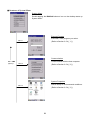
Structure of System Menu
System Menu
Double-tapping the BhtShell shortcut icon on the desktop starts up
System Menu.
Execute Program
Executes a user program you select.
Menu 1
(Refer to Section 2.5.4, [ 1 ].)
Communication
SF + C/BS
(C) keys
Communicates with the host computer.
Menu 2
(Refer to Section 2.5.4, [ 2 ].)
System Properties
Sets a variety of environmental conditions.
Menu 3
(Refer to Section 2.5.4, [ 3 ].)
58
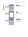
Chapter 2 Getting Started the BHT and System Menu
Hardware Test
Tests a variety of hardware operations.
Menu 4
(Refer to Section 2.5.4, [ 4 ].)
SF + C/BS
(C) keys
Explorer
Runs Explorer.
Menu 5
(Refer to Section 2.5.4, [ 5 ].)
System Information
Shows the system program version and
memory size.
Menu 6
(Refer to Section 2.5.4, [ 6 ].)
59
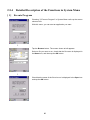
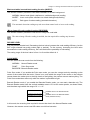
2.5.4
Detailed Description of the Functions in System Menu
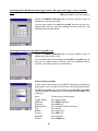
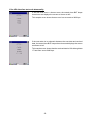
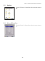
[ 1 ] Execute Program
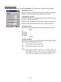
Choosing "1:Execute Program" in System Menu calls up the screen
shown at left.
With this menu, you can start an application you want.
⇓
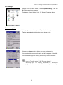
Tap the Browse button. The screen shown at left appears.
Select a file you want to run, check that the file name is displayed in
the Name box, and then tap the OK button.
⇓
Check that the name of the file to be run is displayed in the Open box
and tap the OK button.
60
Chapter 2 Getting Started the BHT and System Menu
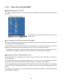
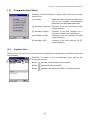
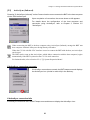
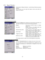
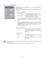
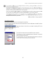
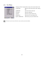
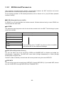
[ 2 ] Communication Menu
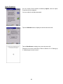
Choosing "2:Communication" in System Menu calls up the screen
shown at left.
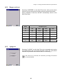
[1] Ymodem:
Switches to the Ymodem menu where you
can set the Ymodem communications
parameters and download/upload files.
[2] ActiveSync (Infrared): Connects to the host computer via IrDA
using ActiveSync.
[2.1]
[3] ActiveSync (Serial):
Connects to the host computer via a
connector interface using ActiveSync.
[4] ActiveSync (USB):
Connects to the host computer via USB
using ActiveSync.
[5] ActiveSync (RF):
Connects to the host computer via RF
using ActiveSync.
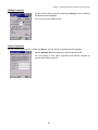
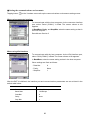
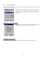
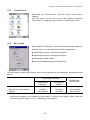
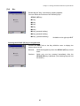
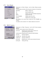
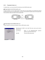
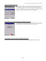
Ymodem Menu
With this menu, you can set the communications parameters and download or upload files from/to the
host computer.
Choosing "1:Ymodem" in the Communication menu calls up the
screen shown at left.
Button
: Sets the communications environments.
Button
: Downloads a file to the BHT.
Button
: Uploads a file stored in the BHT to the host computer.
61
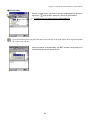
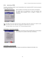
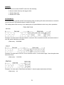
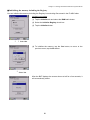
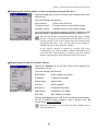
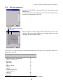
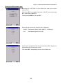
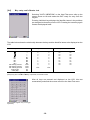
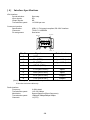
Setting the communications environments
Tapping button
on the Ymodem menu calls up the communications environments setting screen.
When using connector interface
To communicate with the host computer via the connector interface
port, select "Serial (COM1:)" in Port. The screen shown at left
appears.
In BaudRate, Parity, and StopBits, select the same setting as that in
the host computer.
Data bits are fixed at 8.
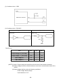
When using IrDA interface
To communicate with the host computer via the IrDA interface port,
select "IrDA (COM4:)" in Port. The screen shown at left appears.
In BaudRate, select the same setting as that in the host computer.
Other settings are fixed as follows:
- Data bits:
- Parity:
- Stop bits:
8
None
1
After the BHT is initialized, the interface port and communications parameters are set as listed in the
default table below.
Items
Defaults
Port
IrDA (COM4:)
Baud Rate
115200 bps
Data Bits
8
Parity
None
Stop Bits
1
62
Chapter 2 Getting Started the BHT and System Menu
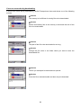
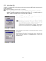
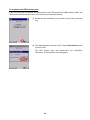
Downloading
Specify a folder where you want to store a downloaded file and then
tap button
, and the BHT waits for a file to be downloaded.
Folder where you want to store a downloaded file
If you download a file having the same name as one already in the same folder, the newly downloaded
file replaces the old one.
⇓
Upon completion of downloading, the BHT sounds a long beep once
and displays the screen shown at left.
63
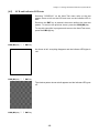
If an error occurs during downloading
If some error occurs during downloading, the BHT beeps three times and shows one of the following
screens.
Problem
The memory is insufficient for storing files to be downloaded.
Solution
Delete unnecessary files in the memory or decrease the size of the
file to be downloaded.
Problem
The path of the file to be downloaded is too long.
Solution
Change the file name or the folder where you want to store the
downloaded file.
Problem
The file you attempted to download was opened.
Solution
Close the file to be downloaded and then retry the download.
64
Chapter 2 Getting Started the BHT and System Menu
Problem
Downloading has failed.
Solution
Confirm the communications environment settings and then retry the
download.
It is also necessary to check the communications environment setup
of the host computer.
Problem
Downloading has aborted.
Solution
Confirm
the
communications
environment
communications log, then retry the download.
settings
and
It is also necessary to check the communications environment setup
of the host computer.
Problem
The communications port has been already opened.
Solution
Close the communications port already opened for other processing
and then retry the download.
Problem
Timeout has occurred.
Solution
Confirm
the
communications
environment
communications log, then retry the download.
settings
and
It is also necessary to check the communications environment setup
of the host computer.
65
Uploading
Specify a file you want to upload and then tap button
waits for a file to be uploaded.
, and the BHT
File you want to upload
⇓
Upon completion of uploading, the BHT sounds a long beep once and
displays the screen shown at left.
66
Chapter 2 Getting Started the BHT and System Menu
If an error occurs during uploading
If some error occurs during uploading, one of the following screens will appear and the beeper beeps
three times.
Problem
The file you attempted to upload was opened.
Solution
Close the file to be uploaded and then retry the upload.
Problem
Uploading has aborted.
Solution
Confirm
the
communications
environment
communications log, then retry the upload.
settings
and
It is also necessary to check the communications environment setup
of the host computer.
Problem
The communications port has been already opened.
Solution
Close the communications port already opened for other processing
and then retry the upload.
67
Problem
Timeout has occurred.
Solution
Confirm
the
communications
environment
communications log, then retry the upload.
settings
and
It is also necessary to check the communications environment setup
of the host computer.
Problem
No file has been correctly selected for uploading.
Solution
Select a file(s) to be uploaded and retry the upload.
68
Chapter 2 Getting Started the BHT and System Menu
[2.2]
ActiveSync (Infrared)
Choosing "2:ActiveSync (Infrared)" on the Communication menu connects the BHT to the host computer
via the IrDA interface port.
Upon completion of connection, the screen shown at left appears.
For details about the configuration of the host computer and
connection using ActiveSync, refer to Chapter 3, Section 3.5
"ActiveSync."
When connecting the BHT to the host computer using ActiveSync (Infrared), arrange the BHT and
host computer with their IrDA ports facing directly each other.
When the CU-201 with RS-232C interface is used to connect the BHT with the host, no ActiveSync
can be used.
The BHT can be setup so that ActiveSync, which allows connection with the host computer, begins
automatically if the BHT is placed on the CU-221 while turned on.
For further details, refer to Section 2.5.4, "[3] System Properties Menu".
If ActiveSync connection succeeds
If ActiveSync connection succeeds, the BHT beeps once and displays
the ActiveSync icon (circled in red at left) in the task tray.
If ActiveSync connection fails
If ActiveSync connection fails, the BHT beeps once and does not display the ActiveSync icon.
69
[2.3]
ActiveSync (Serial)
Choosing "3:ActiveSync (Serial)" on the Communication menu connects the BHT to the host computer
via the connector interface port.
After a connection is established, the screen shown at left appears.
For details about the configuration of the host computer and
connection using ActiveSync, refer to Chapter 3, Section 3.5:
"ActiveSync."
If ActiveSync connection succeeds
If ActiveSync connection succeeds, the BHT beeps once and displays
the ActiveSync icon (circled in red at left) in the task tray.
If ActiveSync connection fails
If ActiveSync connection fails, the BHT beeps once and does not display the ActiveSync icon.
70
Chapter 2 Getting Started the BHT and System Menu
[2.4]
ActiveSync (USB)
Choosing "4:ActiveSync (USB)" on the Communication menu connects the BHT to the host computer
via the USB interface port.
Upon completion of connection, the screen shown at left appears.
For details about the configuration of the host computer and
connection using ActiveSync, refer to Chapter 3, Section 3.5
"ActiveSync."
The BHT can be setup so that ActiveSync, which allows connection with the host computer, begins
automatically when the USB cable is plugged into the BHT when it is turned on.
For further details, refer to Section 2.5.4, "[3] System Properties Menu".
If ActiveSync connection succeeds
If ActiveSync connection succeeds, the BHT beeps once and displays
the ActiveSync icon (circled in red at left) in the task tray.
If ActiveSync connection fails
If ActiveSync connection fails, the BHT beeps once and does not display the ActiveSync icon.
71
[2.5]
ActiveSync (RF)
Choosing "5:ActiveSync (RF)" on the Communication menu connects the BHT to the host computer via
the RF interface port.
Before proceeding to "ActiveSync (RF)," you need to:
- Set up a partnership between the host computer and BHT by running "ActiveSync (Infrared)."
- Make the RF settings according to the procedure given in section 2.5.4 "[3.8] Radio Frequency." If
the RF settings are not made correctly, "ActiveSync (RF)" cannot run.
When the BHT is opening the RF device and connecting to the
network, it displays the screen shown at left.
Connection to the network may take several tens of seconds
depending upon the network environment. (When the DHCP is
used for getting an IP address, connection to the network will
require more time than when the IP address is fixed.)
If connection to the network cannot be completed, the RF settings
may have not been made correctly. Check the RF settings again.
⇓
Upon completion of connection to the network, the screen shown at
left appears.
Select "Network Connection" as connection method and select the
name of the host computer in the Connect to box. Then tap the
Connect button.
⇓
72
Chapter 2 Getting Started the BHT and System Menu
Upon completion of connection by ActiveSync, the screen shown at
left appears.
If connection to the network fails
If connection to the network fails, the BHT beeps three times and displays the following screen.
Solution
The RF settings may have not been made correctly. According to the
procedure given in section 2.5.4 "[3.8] Radio Frequency," make the
correct RF settings.
If no partnership has been set up
If no partnership has been set up between the host computer and BHT, the BHT beeps three times and
displays the following screen.
Solution
Set up a partnership according to the procedure given in Section
3.5.2, "Connection Using ActiveSync."
73
[ 3 ] System Properties Menu
Choosing "3:System Properties" in System Menu calls up the window
shown at left.
[3.1]
[1] QRrcode:
Opens the QRcode menu.
[2] Beeper/Vibration:
Opens the Beeper/Vibration menu.
[3] Control Panel:
Opens the Control Panel window.
[4] File System:
Opens the File System menu.
[5] Power Management:
Opens the Power Management menu.
[6] Key:
Opens the Key menu.
[7] Status Display:
Opens the Status Display menu.
[8] Radio Frequency:
Opens the NIC Control menu.
QRcode
On the System Properties Menu, double-tap the "QRcode", and the
QRcode property appears.
INVERT:
Activates or deactivates the black-and-white
inverted label reading function.
REVERSE:
Activates or deactivates the mirror image 2D
code reading function.
DECODE LEVEL:
Sets the decode level.
SCAN MODE:
Selects the SCAN mode.
MARKER:
Sets the marker ON/OFF mode.
OPTION DATA:
Selects whether or not option data will be
added to the tail of 2D code data read.
MINIMUM DIGITS:
ITF:
Sets the default minimum number of digits to
be read for ITF.
CODABAR:
Sets the default minimum number of digits to
be read for CODABAR.
74
Chapter 2 Getting Started the BHT and System Menu
Black-and-white inverted label reading function (INVERT)
This function makes it possible to read white cells/bars on a black background.
NORMAL: Normal code (black cells/bars on a white background) reading
INVERT: Invert code (white cells/bars on a black background) reading
AUTO:
Both types of codes reading (automatic detection)
The automatic detection reading may take more than normal code or invert code reading.
Mirror image 2D code reading function (REVERSE)
This function makes it possible to read a mirror image 2D code label.
The mirror image 2D code reading is enabled, the time required for reading may increase.
DECODE LEVEL
You may set the decode level. Decreasing the level value increases the code reading efficiency, but the
BHT might misread low-quality codes (split or stained). To the contrary, increasing the level value
decreases the code reading efficiency, but it will diminish the possibility of misreading.
The setting range of the level value is from 1 to 9 and the default is 4.
SCAN MODE
You can select the scan mode from the following:
NORMAL: Normal Reader mode
POINT:
Point Scan mode
BARCODE: Barcode Reader mode
Point Scan mode: If you enable the Point scan mode, you can aim a target code by matching up the
center of the marker with that code. If there is no code within the range of the center or the scanner
cannot detect the marker due to the high levels of the lighting, the scanner cannot read anything. The
Point Scan mode takes effect only when the marker is permitted to light.
Barcode Reader mode: If you enable the Barcode Reader mode, you can read a barcode only. The
Barcode Reader mode limits the vertical readable area to 15% at the center portion, as shown below,
and the skew angle within the range of 0° ≤ θ ≤ 6°.
Readable area in the Normal Reader
mode
Readable area in the Barcode Reader
mode (hatched section)
In this mode, the scanning time required is shorter than that in the Normal Reader mode.
However, the scanner cannot read 2D codes or multi-line barcodes.
75
MARKER
You can select the marker ON/OFF mode from the following:
0: Normal mode driven by the trigger switch
1: Marker-ON mode
2: Marker-OFF mode
OPTION DATA
If the Option Data is set ON, the BHT will add option data (containing 2D code model and error correction
level) to the tail of 2D code data when it reads a 2D code.
This setting takes effect not only in the reading test in System Mode but also in any other operations.
Example: If a code read is "QR code, Model 2, Version 5, Error correction level M, and mask number 6,"
then the option data below will follow.
(Data read)… Q2V05M6
Example: If a code read is "PDF417, Error correction level 4, 12 rows and 2 digits," then the option data
below will follow.
(Data read)… Y1041202
Example: If a code read is "MaxiCode and Mode 4," then the option data below will follow.
(Data read)… X4
76
Chapter 2 Getting Started the BHT and System Menu
Example: If a code read is "Data Matrix, Error correction level ECC200, 10 cells wide by 10 cells high," then
the option data below will follow.
(Data read)... Z0200010010
Minimum number of digits to be read for ITF or CODABAR
You can set the minimum number of digits to be read for ITF and CODABAR.
Setting a small number of digits increases the frequency of digit-missing reading or misreading
depending upon how to scan bar codes or the quality of bar codes. On the other hand, setting a large
number will diminish the possibility of those errors.
The setting range is from 2 to 20 for ITF and from 3 to 20 for CODABAR. The default is 4 for ITF and
CODABAR.
77
[3.2]
Beeper/Vibration
Double-tap the "Beeper/Vibration", and the Beeper/Vibration property
appears.
On this menu, you can adjust the beeper volume and switch the
beeper and vibrator.
Adjusting the beeper volume
Choose the Volume tab to display the screen shown at left where you
can select the beeper volume for the following operations.
Beeper:
From the six levels 0 (low) to 5 (high).
(Default: 5)
Key clicks:
Beeper volume to be applied when any
key is pressed. (Default: Loud)
Half-press key clicks:
Beeper volume to be applied when any
key is halfway pressed. (Default: OFF)
Screen taps:
Beeper volume to be applied when the
screen is tapped. (Default: Loud)
Trigger key clicks*:
Beeper volume to be applied when the
trigger switch is pressed. (Default: OFF)
Marker key clicks*:
Beeper volume to be applied when the
marker key is pressed. (Default: OFF)
* The trigger switch or marker key can be assigned to magic keys.
Switching the beeper and vibrator
Choose the Rumble Device tab to display the screen shown at left.
You may select any of three ways--beeping only, vibrating only, and
beeping and vibrating as a confirmation of completion of bar code
reading.
Beeper:
Beeping only (default)
Vibration:
Vibrating only
Beeper/Vibration: Beeping and vibrating
78
Chapter 2 Getting Started the BHT and System Menu
[3.3]
Control Panel
Double-tap the "Control Panel", and the Control Panel window
appears.
With this menu, you can set up the basic Windows operating
environment. For details, refer to Section 2.5.2 " Control Panel."
[3.4]
File System
Double-tap the "File System", and the File System property appears.
With this menu, you can perform the following transactions:
Initializing the memory excluding the Registry
Initializing the memory including the Registry
Initializing the FLASH folder
Running Scandisk through the FLASH folder
The table below shows which memory area will be initialized by the initialization transactions listed
above.
Initializing the memory
Data stored in the FLASH folder
Data stored in other folders
Registry
Initializing the
FLASH folder
Excluding the
Registry
Including the
Registry
Not initialized
Not initialized
Initialized
Initialized
Initialized
Not initialized
Not initialized
Initialized
Not initialized*
* Note that the backup of the Registry will be erased. To back up the Registry again, follow the
procedure given in Section 2.3.4, "[ 2 ] Backing up the Registry."
79
Initializing the memory excluding the Registry
You can initialize the memory excluding the Registry and files stored in the FLASH folder.
Initializing procedure
(1) Tap the Initialize tab and select the RAM radio button.
(2) Tap the Initialize button.
⇓
⇑ Select No.
(3) To initialize the memory, tap the Yes button; to return to the
previous menu, tap the No button.
⇓ Select Yes.
After the BHT displays the screen shown at left for a few seconds, it
will automatically reboot.
80
Chapter 2 Getting Started the BHT and System Menu
Initializing the memory including the Registry
You can initialize the memory including the Registry but excluding files stored in the FLASH folder.
Initializing procedure
(1) Tap the Initialize tab and select the RAM radio button.
(2) Select the Initialize Registry check box
(3) Tap the Initialize button.
⇓
⇑ Select No.
(4) To initialize the memory, tap the Yes button; to return to the
previous menu, tap the No button.
⇓ Select Yes.
After the BHT displays the screen shown at left for a few seconds, it
will automatically reboot.
81
Initializing the FLASH folder
You can erase all information stored in the FLASH folder and let the folder revert to the initial state.
Initializing procedure
(1) Tap the Initialize tab and select the FLASH radio button.
(2) Tap the Initialize button.
⇓
⇑ Select No.
(3) To initialize the memory, tap the Yes button; to return to the
previous menu, tap the No button.
⇓ Select Yes.
Upon completion of initialization (it will take approx. one minute), the
screen shown at left appears.
82
Chapter 2 Getting Started the BHT and System Menu
Running Scandisk through the FLASH folder
If the power to the BHT is shut down when the FLASH folder is being accessed, some broken file
fragments may remain in the FLASH folder so that the free memory space will be decreased.
To remove or clear those fragments, run Scandisk through the FLASH folder.
Initializing procedure
(1) Tap the Scandisk tab and select the Scandisk button.
⇓
⇑ Select No.
(2) To initialize the memory, tap the Yes button; to return to the
previous menu, tap the No button.
⇓ Select Yes.
Upon completion of Scandisk (it may take a few minutes depending
upon the use conditions of the FLASH folder), the screen shown at
left appears.
83
[3.5]
Power Management
Double-tap the "Power Management", and the Power Management
property appears.
You can set the automatic power-off timer, the standby timer, and
CPU clock.
Automatic Power-Off Time:
Battery Power:
For the BHT being out of the CU, set the
automatic power-off timer. (Default: 180)
External Power:
For the BHT placed in the CU, set the
automatic power-off timer. (Default: 0)
The entry range for the above items is from 0 to 32767 in units of
seconds. Specification of 0 disables the automatic power-off
facility.
When the “Enable automatic power off with wireless
communication” check box is selected, the power turns OFF
automatically when not performing communication, even if a
wireless connection is open.
Switch to Standby Mode:
Timer (x100 ms):
Set the waiting time to switch to the standby
mode within the range from 0 to 32767 in
units of 100 ms. (Default: 10, 100 ms x 10 = 1
second)
CPU Performance:
Normal:
Select Normal to operate the CPU at typical
clock speed. (Default)
Fast:
Select Fast to operate the CPU at higher
clock speed.
• Setting the CPU performance to Fast consumes much power, decreasing the BHT operation period
after battery charge.
• CPU performance settings will be functional after the setting changes are made.
84
Chapter 2 Getting Started the BHT and System Menu
[3.6]
Key
Double-tap the "Key", and the Key property appears.
You can define the functions of the following keys:
- SF/ALP (SF) key
- M1 key
- M2 key
- M3 key
- M4 key
- M5 key*
- M3 key (pressed halfway)
- M4 key (pressed halfway)
- M5 key* (pressed halfway)
*Available on the grip style BHT
Defining the SF/ALP (SF) key for keypad shift
Choose the SHIFT tab on the Key definition menu to display the
screen shown at left.
Nonlock:
Shifts the keypad only when the SF/ALP (SF) key is held
down.
Onetime:
Shifts only one key pressed immediately after the
SF/ALP (SF) key is pressed. (The following keys will not
be shifted.)
85
Defining the M1, M2, M3 (left-hand trigger switch), M4 (right-hand trigger switch), and M5*
keys
*M5 key available on the grip style BHT
Choose the MAGIC Full-press tab on the Key definition menu to
display the screen shown at left.
You can define each of the M1 through M5* keys as any one of a
trigger switch, shift key, enter key, backlight function on/off key, Tab
key and others as listed below.
Defining the halfway pressed M3 through M5* keys
Choose the MAGIC Half-press tab on the Key definition menu to
display the screen shown at left.
You can define each of the halfway pressed M3 through M5* keys as
any one of a trigger switch, shift key, enter key, backlight function
on/off key, Tab key and others as listed below.
Choice of keys available
In each of the combo boxes on the MAGIC Full-press and Half-press
pages above, you can make a choice from a list of keys given below.
The M1 through M5* keys and the halfway pressed M3 through M5*
keys can function as listed below. (This sample defines the M1 key as
a Tab key.)
None:
Trigger Switch:
Shift Key:
Enter Key:
Backlight Key:
Tab:
Marker:
Control:
Alternate:
CLEAR:
The key entry will be ignored.
As a trigger switch.
As a SF/ALP (SF) key.
As an ENT key.
As a backlight function on/off key.
As a tab key.
As a marker key.
As a CNTL key.
As an ALT key.
As a CLEAR key.
86
Chapter 2 Getting Started the BHT and System Menu
If you define the M4 key as a backlight function on/off key, pressing the M4 key activates or
deactivates the backlight function.
Note that the backlight function on/off key can be assigned only to any one of M1 through M5* keys
and halfway pressed M3 through M5* keys. The key defined more recently will act as a backlight
function on/off key and one defined earlier will be ignored.
That is, if you define the M1 and M2 keys as a backlight function on/off key in this sequence, the M2
key will work as a backlight function on/off key and the M1 key's entry will be ignored.
If a backlight function on/off key is not assigned to any of the M1 through M5* keys and halfway
pressed M3 through M5* keys, the combination of the SF/ALP (SF) and M4 keys work as a
backlight function on/off key by default.
*M5 key available on the grip style BHT
User-defined code file
User-defined virtual key codes can be assigned to magic keys.
Enter the desired virtual key codes into a text file and save it in the FLASH folder of the BHT, with the
filename “MKeyDef.txt”.
The screen shown to the left is an example for adding ALT+X and
ALT+Y.
The code file is read when the Key definition menu is started
The defined key codes are displayed below “Alternate” in the same
order as entered in the text file.
For further details, refer to the "BHT-200-CE API Reference Manual"
or "BHT-200-CE Class Library Reference Manual."
87
[3.7]
Status Display
Double-tap the "Status Display", and the Status Display property
appears.
You can display or hide the following status indicators in the task tray:
BATTERY:
Battery voltage level
RF
Synchronization state
SIP:
Software input panel (Software keyboard)
SHIFT:
Keypad shift state
CPU STANDBY:
Standby state of the CPU
ALPHA:
Alphabet entry mode status
The defaults of the items above except the CPU STANDBY are
"Display."
For details, refer to Section 2.2.2, "Status Indicators on the LCD."
[3.8]
Radio Frequency
Double-tap the "Radio Frequency", and the NIC Control property
appears.
The NIC Control property has the following tabs:
Info tab:
Displaying the wireless module version and
opening/closing the RF device
Network tab: Displaying the IP address and MAC address
ID tab:
Setting the ESSID
Option tab:
Setting the RF options
WEP tab:
Setting the WEP keys
Link tab:
Displaying the current communications link status
Ping tab:
Testing with Ping
88
Chapter 2 Getting Started the BHT and System Menu
Displaying the wireless module version and opening/closing the RF device
Tapping the Info tab on the NIC Control menu displays the screen
shown at left.
This menu displays the following:
Driver Version:
Version of the RF driver
Firmware Version:
Firmware version of the wireless module
Hardware Version:
Hardware version of the wireless module
You can also open or close the wireless module by tapping the RF
Open, RF Close or RF Open Continuously button, respectively
If the wireless module is opened by pressing [RF Open], Closing
the NIC Control property automatically closes the RF device even
if being opened. If you need to display any other window while
keeping the RF device open, tap the button on the taskbar to
minimize the NIC Control property window.
If the wireless module is opened by pressing [RF Open
Continuously], the wireless module remains continuously open
even if the NIC Control property is closed. To close the wireless
module, open this menu again and tap the [RF Close] button.
Displaying the IP address and MAC address
Tapping the Network tab on the NIC Control menu displays the
screen shown at left.
This menu displays the following:
DHCP/Static:
DHCP enabled or disabled
IP Address:
IP address of the BHT
Subnet mask:
Subnet mask
Gateway:
Default gateway
DNS Server:
IP address of the DNS
WINS Server:
IP address of the WINS
MAC Addr:
MAC address of the BHT
Tapping the Property button calls up the IP address setting screen.
For the IP address setting procedure, refer to Section 2.5.2, "
Control Panel, Owner Properties."
When the RF device is not opened, the MAC address shows
"00:00:00:00:00:00."
89
Setting the ESSID
Tapping the ID tab on the NIC Control menu displays the screen
shown at left.
You can specify an ESSID (Extended Service Set ID) to be used on
the communications network. For details about the ESSID, refer to
Chapter 3, Section 3.1.2, "RF-Related Parameters."
Setting the RF options
Tapping the Option tab on the NIC Control menu displays the screen
shown at left.
You can set the following:
Power:
Select the power mode for the wireless module.
Zero config:
Select the Zero config mode.
For details about the parameters above, refer to Chapter 3, Section
3.1.2 "RF-Related Parameters."
90
Chapter 2 Getting Started the BHT and System Menu
Setting the WEP keys
Tapping the WEP tab on the NIC Control menu displays any of the
following three types of screens according to the authentication type.
- At left:
Open
- Below at left:
Shared key (40-bit WEP)
- On the next page: Shared key (128-bit WEP)
You can set the following:
WEP:
Set the authentication system when the WEP is enabled.
Open:
Disable the encryption.
Shared (40-bit): Use a 40-bit WEP key.
Shared (128-bit): Use a 128-bit WEP key.
(Authentication: Open)
Key 1 through 4: Define four types of encryption keys--WEP keys
1 to 4. (available only when the Shared (40-bit)
or Shared (128-bit) is selected)
Transmit Key:
Activate any one of the WEP keys 1 through 4
already defined. (available only when the Shared
(40-bit) or Shared (128-bit) is selected)
To enable the encryption with an WEP key, choose "Shared" in the
WEP box.
For Transmit Key, select an WEP key already defined.
(40-bit WEP)
For details about each parameter, refer to Chapter 3, Section 3.1.2,
"RF-Related Parameters."
(128-bit WEP)
91
Displaying the current communications link status
Tapping the Link tab on the NIC Control menu displays the screen
shown at left where the current communications link status appears in
real-time.
Associated Access Point:
Displays the MAC address assigned to the wireless
interface of the associated access point.
Signal Strength:
Displays the signal intensity of receive packets.
Beacons Received:
Displays the progress bar that shows the percentage of
received beacon packets relative to those to be received.
Beacon: Synchronous signals transmitted periodically
from the access point
Link Quality:
Displays the comprehensive link operation level with the
access point.
If the following shows:
Communications state
Excellent
Excellent communications link
Good
Fair
Poor
Poor communications link
Not Associated
Not associated with an access point
Link Speed:
Displays the current transmission speed.
Channel:
Displays the current communications channel.
Tapping the Link tab when the RF device is not opened automatically opens the RF device and
displays the current communications link status.
92
Chapter 2 Getting Started the BHT and System Menu
Testing with Ping
Tapping the Ping tab on the NIC Control menu displays the screen
shown at left.
Dest IP:
Specify the IP address of a host computer that
you want to ping.
Data size:
Specify the data size of an echo request.
Interval:
Specify the echo request intervals (in units of
100 ms).
Timeout:
Specify the timeout period (in units of 100 ms)
for an echo request.
Type 1 or Type 2: Select the echo request send timing Type 1 or
Type 2 (described on the next page).
Count:
Specify the number of echo requests to be sent.
To run Ping, tap the Ping Start button or press the ENT key.
Tapping the Ping Start button when the RF device is not opened automatically opens the RF device
and runs Ping.
Entry Range for Data size, Interval, Timeout, and Count
Item
Allowable entry range
Initial value
Data size
1 to 2048
32
Interval
0 to 65535
10
Timeout
0 to 65535
10
Count
0* to 65535
4
* Specification of zero (0) will set the number of echo requests to be sent to "infinite," keeping sending
echo requests (until Ping is aborted).
If you specify a value out of the allowable entry range listed above, the nearest value within the range will
automatically apply.
After Ping runs, the screen shown at left appears.
Count:
Number of echo requests sent
OK:
Number of echo replies
NG:
Number of errors found during execution of Ping
Timeout:
Number of timeouts (for echo replies) that took
place during execution of Ping
RTT Ave. (ms):
Echo reply time in milliseconds
93
Ping Echo Request Send Timing
Two types of echo request send timings are available: Type 1 and Type 2. The default is Type 2.
• Type1
After sending an echo request, Ping will wait for the period specified by Interval and then send an echo
request again.
For Type 1, the relationship between the Interval and Timeout should be "Interval ≥ Timeout."
Sends an echo request
Receives an echo reply
Timeout period
Interval
Sends an echo request
• Type2
After sending an echo request, Ping will wait for an echo reply to be received or for timeout to occur. After
that, Ping will wait for the period specified by Interval and then send an echo request again. For Type 2,
no relationship between the Interval and Timeout is required.
If Ping receives an echo reply:
Sends an echo request
Receives an echo reply
Interval
Sends an echo request
If timeout occurs:
Sends an echo request
Timeout period
Timeout occurs
Interval
Sends an echo request
94
Chapter 2 Getting Started the BHT and System Menu
Backup Battery Discharge Counter
On the System Properties Menu, pressing the 0 key with the SF/ALP
(SF) key held down calls up the screen shown at left.
This screen displays the discharge count of the backup battery.
If you replace the backup battery, tap the Reset button to reset the
discharge counter to zero.
Only after the discharge count reaches 200, the counter can be
reset to zero.
ActiveSync automatic connection
On the System Properties Menu, pressing the 1 key with the SF/ALP
(SF) key held down calls up the screen shown at left.
On the ActiveSync page, select “Infrared” or “USB” in the “Automatic
Connection” group box.
Infrared:
Turns on automatic connection via the infrared port
USB:
Turns on automatic connection via the USB port
Tapping the OK button validates the setting.
* The CU-221 is needed.
Automatic connection is disabled by default.
95
[ 4 ] Test Menu
Choosing "4:Test" in System Menu calls up the screen shown at left.
[1] QRCODE:
Select the 2D-code and bar-code reading
test.
[2] BEEPER:
Select the beeper scale test.
[3] AGING:
Select the aging test.
[4] COM:
Select the communications test.
[5] DISPLAY:
Select the LCD and indicator LED.
[6] KEY VIBRATION:
Select the key entry and vibrator test.
If an error occurs in any of the above tests, contact your nearest dealer.
96
Chapter 2 Getting Started the BHT and System Menu
[4.1]
QR code reading test
Selecting "1: QRCODE" on the Hard Test menu calls up the screen
shown at left.
Actually read codes with the BHT and check that the code data read
matches ones displayed on the LCD.
⇓
code type
Number of digits of the bar code
Data read
Upon completion of code reading, the BHT beeps once, turns on the
indicator LED in blue, and displays the read data together with the
code type and the number of digits.
Listed below is a table showing the relationship between the code types and the identifier letters to be
displayed on the LCD.
Code Type
QR Code, MicroQR
Split QR Code (In non-edit mode)
PDF417, MicroPDF417
MaxiCode
Data Matrix
RSS
EAN-13, UPC-A
EAN-8
UPC-E
Interleaved 2of5 (ITF)*
Codabar (NW-7)*
Code 39
Code 128
EAN-128
ID Letters
Q
S
Y
X
Z
R
A
B
C
I
N
M
K
W
* The minimum number of digits to be read is 4 for ITF and 3 for Codabar.
97
The QR Code symbology can split data into a maximum of 16 blocks and encodes each of them into a
split QR code image.
When reading split QR codes, the BHT beeps in a different way from usual. That is, when the BHT
reads the first split code, it beeps twice and enters the split code scanning mode. After that, each time
it reads the subsequent split code, it beeps once. If the BHT reads the last split code, it beeps three
times and completes the sequence of split code scanning.
The scanned data will not be displayed on the LCD until a sequence of split code scanning is
completed.
If you scan any non-split QR code midway in a sequence of split code scanning, the BHT displays the
scanned non-split code, cancels the split code scanning mode, and discards those split codes being
scanned. The same occurs also if you release the trigger switch or the split code scanning interval
exceeds approx. 5 seconds.
The scanning order of split QR codes is arbitrary. The same split code will never be double-read.
98
Chapter 2 Getting Started the BHT and System Menu
[4.2]
Beeper scale test
Selecting "2:BEEPER" on the Hard Test menu calls up the screen
shown at left and sounds the beeper at three octaves listed below.
Upon completion of this test, the BHT automatically returns to the
Hard Test menu.
Scale
[4.3]
Frequency (Hz)
do
523
1046
2093
4186
re
587
1174
2349
-
mi
659
1318
2637
-
fa
698
1396
2793
-
sol
783
1567
3135
-
la
880
1760
3520
-
ti
987
1975
3951
-
Aging test
Selecting "3:AGING" on the Hard Test menu proceeds to the aging
test while showing the current date and time on the LCD. (This test is
intended for personnel who check the BHT in the factory.)
Once this test is selected, the automatic powering-off function
becomes disabled.
99
[4.4]
Communications test
In System Menu, you can test the IrDA interface port and USB interface port.
Preparation for the IrDA interface test
Arrange two BHTs, one as a master station and the other as a slave station (to be tested) with their IR
ports facing each other as illustrated below. In this test, the slave BHT transmits data to the master BHT
and receives the data sent back from the master BHT.
Data
0.15 m
(5.9") or less
Master BHT
Slave BHT (to be tested)
Preparation for the USB interface test
Connect the BHT and the host computer using a USB interface cable.
Selecting the "4:COM" on the Hard Test menu calls up the screen
shown at left.
[1] OPTICAL:
Switch to the MASTER/SLAVE
screen for the IrDA interface test.
[2] USB:
Test the USB interface port.
100
selection
Chapter 2 Getting Started the BHT and System Menu
Testing the IrDA interface port
Selecting the "1:OPTICAL" on the COM menu calls up the screen
shown at left.
At the slave BHT to be tested, select the "1:SLAVE" and at the master
BHT, select the "2:MASTER."
Then press the ENT key on each BHT.
During the test, the screen shown at left is displayed.
XXXXX: Transmission speed (2400, 9600, or 115200 bps)
YYY:
Hex data being sent (0 to 256)
Upon normal completion of the test, the tested slave BHT beeps once
and displays the screen shown at left.
The master BHT automatically returns to the COM menu.
101
If the IrDA interface test ends abnormally:
If the test ends due to a timeout error, the tested slave BHT beeps
three times and displays the screen as shown at left.
This sample screen shows that an error has occurred at 2400 bps.
If the test ends due to mismatch between the sent data and received
data, the tested slave BHT beeps three times and displays the screen
as shown at left.
This sample screen shows that the received data is 196 although data
17 has been sent at 2400 bps.
102
Chapter 2 Getting Started the BHT and System Menu
Testing the USB interface port
Selecting the "2:USB" on the COM menu calls up the screen shown at
left and starts connecting with the host computer using ActiveSync.
For the configuration of the host computer and details about
ActiveSync, refer to Chapter 3, Section 3.5 "ActiveSync."
If ActiveSync connection succeeds via the USB interface port
If ActiveSync connection succeeds, the BHT beeps once and displays
the ActiveSync icon (circled in red at left) in the task tray.
If ActiveSync connection fails via the USB interface port
If ActiveSync connection fails, the BHT beeps once and does not display the ActiveSync icon.
103
To terminate the USB interface test
There are two ways to terminate the USB interface test--"Disconnect the USB interface cable" and
"Disconnect the link with the button in the task tray (as described below)."
(1) Double-tap the ActiveSync icon (circled in red at left) in the task
tray.
(2) The dialog appears as shown at left. Tap the Disconnect button
(circled in red).
The BHT beeps once and disconnects the ActiveSync
connection. The ActiveSync icon disappears.
104
Chapter 2 Getting Started the BHT and System Menu
[4.5]
LCD and indicator LED tests
Selecting "5:DISPLAY" on the Hard Test menu calls up the test
pattern shown at left on the LCD and turns on the indicator LED in
blue.
Each time the ENT key is pressed, the screen shifts to the next test
pattern. To return to the previous screen, press the C/BS (BS) key.
To stop this test while in progress and return to the Hard Test menu,
press the C/BS (C) key.
C/BS (BS) key ⇑
⇓ ENT key
As shown at left, everything disappear and the indicator LED lights in
red.
C/BS (BS) key ⇑
⇓ ENT key
The checker pattern shown at left appears and the indicator LED goes
off.
C/BS (BS) key ⇑
⇓ ENT key
105
The checker pattern is reversed.
C/BS (BS) key ⇑
⇓ ENT key
The gray screen appears with a one-dot wide white outline.
C/BS (BS) key ⇑
⇓ ENT key
Forty eight right-angled triangles appear.
C/BS (BS) key ⇑
⇓ ENT key
106
Chapter 2 Getting Started the BHT and System Menu
The gradation pattern appears.
Press the ENT key, and the BHT returns to the Hard Test menu.
107
[4.6]
Key entry and vibrator test
Selecting "6:KEY VIBRATION" on the Hard Test menu calls up the
screen shown at left and makes the BHT ready for entry from the
keypad.
Pressing individual keys displays the identifier letters in the positions
pre-assigned to those keys on the LCD. Pressing the same key again
erases the displayed letter.
The table below shows the relationship between the keys and the identifier letters to be displayed on the
LCD.
Key
M1
M2
M3
M4
M5 *
M3 halfway pressed
M4 halfway pressed
M5* halfway pressed
SF/ALP (SF)
C/BS (BS)
Letter
Key
Letter
Key
Letter
^
v
>
<
M1
M2
M3
M4
M5
M3H
M4H
M5H
SF
BS
1
2
3
4
5
6
7
8
9
0
.
ENT
1
2
3
4
5
6
7
8
9
0
.
ENT
F1
F2
F3
F4
F5
F6
F7
F8
F9
F0
F1
F2
F3
F4
F5
F6
F7
F8
F9
F0
*M5 available on the grip style BHT
(Note) Only when the M1 or M2 key is pressed, the vibrator works.
After all keys are pressed and displayed on the LCD, this test
automatically ends and the screen returns to the Hard Test menu.
(M5 and M5H appear only on the grip
style BHT.)
108
Chapter 2 Getting Started the BHT and System Menu
[ 5 ] Explorer
Choosing "5:Explorer" in System Menu calls up the screen shown at
left.
[ 6 ] System Information
Choosing "6:Version" in System Menu calls up the screen shown at
left.
109
2.6 Wireless Zero Configuration (WZC)
The screen on the left displays if a wireless local area network
(wireless LAN) environment has not yet been established following
purchase of the BHT unit. (BHT-202QW-CE only)
If this screen does not display, double-tap the Wireless Zero
Configuration status icon in the task tray to display.
Wireless Zero Configuration status
Indicates that the Wireless Zero Configuration (WZC) radio
is connected to a wireless network.
Indicates that the Wireless Zero Configuration (WZC) radio
is not connected to a wireless network.
Synchronization state
Displays when the wireless device is open.
Shows the radio field intensity with the number of bars.
The WZC menu has the following tabs:
IP Information:
Displays information such as the IP address.
Wireless Information: Used to perform wireless communication
settings.
The radio field intensity icons ( ,
, and ) indicate that
the radio link is established but do not assure you that there
will be few communications errors.
110
Chapter 2 Getting Started the BHT and System Menu
IP Information
Tapping the IP Information tab on the WZC Menu displays the
screen shown at left.
Internet Protocol (TCP/IP) settings information displays at this menu.
Renew: Updates with the latest information.
Details: Displays detailed information.
Tapping the Details… button on the IP Information tab displays the
screen shown at left.
Displays detailed information for the network settings.
Physical Address:
Displays the MAC address for the BHT
internal Network Interface Card.
IP Address:
Displays the IP address.
Subnet Mask:
Displays the subnet mask address.
Default Gateway:
Displays the default gateway address.
DHCP Server:
Displays the DHCP server address.
Lease Obtained:
Displays the time and date at which the IP
address was obtained from the DHCP server.
Lease Expires:
Displays the time and date at which the IP
Address became invalid.
DNS Servers:
Displays the DNS servers address.
WINS Servers:
Displays the WINS servers address.
Please refer to section 2.5.4 “Detailed Description of the Functions in
System Menu [3.8] Radio Frequency” for details of settings for the IP
address and so forth.
111
Wireless Information
Wireless Properties
Tapping the Wireless Information tab on the WZC Menu displays
the screen shown at left.
The SSID list for which a search was performed automatically by the
BHT displays.
If automatic recognition is not made, double-tap Add New… and
manually input the SSID.
Please refer to section 3.1.2 “RF-Related Parameters” for further
details on the SSID.
Tap the SSID for which a connection is to be made from the SSID list,
and then tap the Connect button to begin connecting to the wireless
network.
Double-tap an SSID from the SSID list in the Wireless Information
tab to display the screen on the left.
Perform settings to connect to the wireless network.
You can set the following:
Network name (SSID):
Displays the SSID. Manually input the SSID if it is not
automatically recognized.
This is an ad hoc network:
Do not check this check box because ad hoc mode is not
supported.
Encryption:
Select the encryption mode.
Authentication:
Set the authentication system when the WEP is enabled.
Network key:
Enter the network key.
Key index:
Enter the network key index.
112
Chapter 2 Getting Started the BHT and System Menu
This key is provided automatically:
Select this check box to automatically obtain the network key.
Enable 802.1X authentication:
Select this check box to enable 802.1X authentication.
* This cannot be used in Ad hoc mode.
• Security and Setting Method
The security level can be changed based on combinations of the encryption and authentication. The
setting parameters for each security level are shown in the table below.
Setting
parameter
Encryption
Authentication
Network key
Key index
The key is
provided
automatically
Enable 802.1X
authentication
EAP type
None
PEAP
(802.1x)
Security
EAP-TLS
(802.1x)
PEAP
(WPA)
EAP-TLS
(WPA)
PSK
(WPA)
Disabled
Open
–
–
WEP
Open
xxxxxx
1 to 4
WEP
Open
–
–
WEP
Open
–
–
TKIP
WPA
–
–
TKIP
WPA
–
–
TKIP
WPA-PSK
xxxxxx
–
–
*
√
√
–
–
–
–
*
√
√
–
–
–
–
–
PEAP
TLS
PEAP
TLS
–
(Note)
– : No entry possible
√ : Select
* : No entry or no selection
xxxxxx : Enter the network key.
113
• Settings when PEAP, TLS Selected for EAP Type
Tapping the Properties… button on the Wireless Properties window
displays the screen shown at left.
Displays the User Certificate issuance information.
Select the Validate Server check box to enable the certificate server.
Default: Enabled
When TLS is selected for the EAP type, tapping the Select… button
on the Authentication Settings window displays the screen shown at
left.
The Certificates list displays.
Tap a certificate from the list, and then tap the View Certificate…
button to display detailed information.
114
Chapter 2 Getting Started the BHT and System Menu
Advanced Wireless Settings
Tap the Advanced… button from the Wireless Information tab to
display the screen on the left.
Use Windows to configure my wireless settings:
Select this check box to automatically perform wireless network
settings at Windows CE. This check box should always be
selected.
Preferred Networks:
Displays the Preferred networks SSID list.
Tap an SSID and then tap either the Up or Down button to change
the order in which the SSID displays in the list.
Tap an SSID and then tap the Delete button to delete that SSID
from the list.
Try network connections shown on the “Preferred Networks”
display, from the SSID at the top.
Automatically connect to non-preferred networks:
Select this check box to display accessible non-preferred
networks, enabling a selection to be made.
Networks to access:
Used to select a network filter.
All available:
Both of following
Only access points:
Between BHT and access point
Only computer-to-computer: Between BHT and other device
If the “Automatically connect to non-preferred networks” check box
is selected, this is applicable to both preferred networks and
non-preferred networks. If the check box is not selected, it is
applicable between preferred networks only.
Wireless Networking Log
Tapping the Log… button on the Wireless Information tab calls up the
Wireless networking Log.
The wireless networking log displays.
115
Chapter 3
Communications Operations of
the BHT-202Q/202QW-CE
Describes the communications operations of the BHT—the spread spectrum communication
(BHT-202QW-CE only), infrared communication, USB interface specifications, basic communications
specifications, communication using Ymodem, and ActiveSync--for data transfer with the host PC or
other devices.
3.1
Spread Spectrum Communication ..................................................................................................................117
3.1.1 Notes for Wireless Operations..................................................................................................................117
3.1.2 RF-Related Parameters............................................................................................................................118
3.2
Infrared Communication..................................................................................................................................120
3.3
Connector interface specification ....................................................................................................................121
3.4
Basic Communications Specifications and Ymodem ......................................................................................123
3.4.1 Basic Communications Specifications ......................................................................................................123
3.4.2 Using Ymodem .........................................................................................................................................125
3.5
ActiveSync ......................................................................................................................................................126
3.5.1 Configuring the Host PC ...........................................................................................................................126
3.5.2 Connection Using ActiveSync...................................................................................................................128
116
Chapter 3 Communications Operations of BHT-202Q/202QW-CE
3.1 Spread Spectrum Communication
3.1.1
Notes for Wireless Operations
The BHT-202QW-CE supports spread spectrum communication.
• If there are too many communications errors, first make sure that the BHT-202QW-CE points directly
at an access point because the 2.4-GHz band requires a more or less straight line path. Note also that
the low-power radio waves have trouble passing through human bodies and other obstacles along that
path.
• This link will not operate properly in the vicinity of microwave ovens, industrial heaters, high-frequency
medical equipment, and other sources of radio waves in the 2.4-GHz band.
• Electromagnetic noise from personal computers, refrigerators, and other home appliances can also
interfere with link operation.
• Environmental factors that can also interfere with link operation include large metallic objects, metallic
dust, or metallic walls in the vicinity of the path and vibration at either end.
To System Designers:
• Before developing the application, make sure that the intended environment is free of the
interference factors above and thus actually capable of supporting link operation.
• Assume that there will be communications failures requiring robust retry capabilities in the
software.
• When introducing the BHT link operation into an environment where equipment using radio waves
in the 2.4-GHz band operates or when introducing such equipment after the introduction of the
BHT link operation, be sure to confirm that the BHT radio link operates properly with all
equipment being in operation beforehand.
• If the environment of the radio communications system is changed after the introduction (e.g.,
newly installed household appliances and movement/addition of shelves or objects), then confirm
that the radio link operates properly again before the actual use.
117
3.1.2
RF-Related Parameters
User programs command-control wireless communication between the BHT terminals and access
points which are connected each other by a wireless LAN.
For the setting procedure of RF-related parameters, refer to Section 2.5.4, "[3.4] RF Menu (Network
Interface Control)."
ESSID (Extended Service Set ID)
An ESSID is an ID that identifies the wireless network. Wireless devices having a same ESSID can
communicate with each other.
POWER
This parameter sets the power mode for the wireless module built in the BHT. The following six power
modes are available.
Power mode
Power consuming state
Full
Consumes much power.
Most (Default)
More
Mid
Less
Least
Consumes less power. The BHT may take more time to establish
the wireless link or send response messages.
WEP (Wired Equivalent Privacy)
You can use either one of the two KEYs—OPEN and SHARED KEY to disable and enable the
authentication, respectively. The WEP KEY uses 40-bit (10-digit hexadecimal) or 128-bit (26-digit
hexadecimal) encryption word.
The BHT is able to definitely communicate with access points having the same WEP KEY.
WEP KEY
You can set four types of encryption keys (WEP KEY1 through WEP KEY4). If you enable WEP, choose
any one of WEP KEY1 through WEP KEY4 as TRANSMIT KEY.
118
Chapter 3 Communications Operations of BHT-202Q/202QW-CE
TRANSMIT KEY
You need to use the TRANSMIT KEY in order to choose and activate any one of the WEP KEY1 through
WEP KEY4 already defined.
If the size of the WEP KEY specified as a TRANSMIT KEY for the BHT is different from that for the
access point, no communication is possible.
Setting example: Communication is possible
- BHT:
Access point:
- BHT:
Access point:
WEP KEY1=128bit, TRANSMIT KEY=WEP KEY1
WEP KEY1=128bit, TRANSMIT KEY=WEP KEY1
WEP KEY1=128bit, WEP KEY3=128bit, TRANSMIT KEY=WEP KEY1
WEP KEY1=128bit, WEP KEY3=128bit, TRANSMIT KEY=WEP KEY3
Setting example: Communication is not possible
- BHT:
Access point:
- BHT:
Access point:
WEP KEY1=40bit, TRANSMIT KEY=WEP KEY1
WEP KEY1=128bit, TRANSMIT KEY=WEP KEY1
WEP KEY1=128bit, WEP KEY3=40bit,TRANSMIT KEY=WEP KEY1
WEP KEY1=128bit, WEP KEY3=40bit,TRANSMIT KEY=WEP KEY3
119
3.2 Infrared Communication
The BHT has an integrated infrared (IR) communications device which enables wireless transfer of
programs and data between the BHT and the host PC and between the BHTs, instead of the
conventional wire transfer.
The IR communications device features the following:
• Wireless communications
• Small and lightweight design
• Freedom from the codes/regulations and licenses which differ from country to country, unlike
radio devices
The BHT may communicate with other IrDA-compliant equipment just by aligning their IR ports with each
other. The effective IR range and IR port angle may differ depending upon the target equipment, so
observe the instructions given in manuals furnished with such equipment.
If IR transfer fails, bring the BHT closer to the target station or change the IR port angle, and try
again.
The BHT's IR communications device is IrDA-compliant. IrDA stands for Infrared Data Association,
which has defined hardware (IrDA Serial Infrared Physical Layer Link) and communications protocols for
IR communications.
The BHT's physical layer complies with the IrDA1.2, with a maximum transfer distance of 0.15 m (5.9
inches) and maximum transmission rate of 115.2 kbps per second.
120
Chapter 3 Communications Operations of BHT-202Q/202QW-CE
3.3 Connector interface specification
The BHT-202QW-CE is equipped with a USB interface for interfacing with the host PC, and with a
connector interface for communicating with the host PC.
(1) Specification
• USB1.1, Full-speed compliant
• RS-232C interface
(2) Connector : TCX3171 HOSIDEN
Pin 8
Pin 2
Pin 1
Pin 7
Pin No
Signal name
Data direction
−
1
GND
2
D+ (USB)
Input / Output
3
D- (USB)
Input / Output
4
VBUS (USB)
5
CTS (RS-232C)
Input
6
RxD (RS-232C)
Input
7
RTS (RS-232C)
Output
8
TxD (RS-232C)
Output
−
(Note) 1.The input/output direction is stipulated from the BHT side.
2.Use the exclusive cable only.
121
(3)-1 Interface circuit(USB)
USB Driver/Receiver
(3)-2 Interface circuit(RS-232C)
Output circuit
Input circuit
TxD, RTS
RxD, CTS
5kΩ
Signal Level
Item
Min.
Typ.
Max.
Output voltage″H″ (3 KΩ load)
5V
――
15V
Output voltage ″L″ (3 KΩ load)
-15V
――
-5V
Input voltage ″H″
3V
――
15V
Input voltage ″L″
-15V
――
-3V
(NOTE)(1) Input / Output voltage are specified at the terminal of the interface connector.
(2) Output voltage becomes unsettled when the connector communication device file is
closed.
(3) Output voltage shall be under the following conditions :
Power voltage: Rated voltage
Load resistance: 3 kΩ
122
Chapter 3 Communications Operations of BHT-202Q/202QW-CE
3.4 Basic Communications Specifications
and Ymodem
3.4.1
Basic Communications Specifications
Listed below are the communications specifications when the BHT exchanges data with a host PC
through the CU-200 (IrDA interface).
IrDA Interface
Synchronization
Start-stop
Transmission Speed
2400, 9600, 19200, 38400, 57600, or 115200 bps
Transmission Code
ASCII 8-bit code
Transmission Bit Order
LSB (Least significant bit) first
Vertical Parity
None
Synchronization
For accurate data transaction, it is very important to synchronize the transmission between the sender
and receiver. To do this, it is required to previously define the bit order and position, the character length,
and the beginning and end of the character to be transmitted.
The start-stop synchronization is an asynchronous system which synchronizes each character as a unit;
that is, it externally adds start and stop bits to the leading and trailing bit positions of the character to be
transmitted, respectively. A clock starts counting on receiving the start bit and it falls into a
non-communication state on receiving the stop bit. The number of the stop bits is selectable (1 or 2 bits).
Transmission Speed
Maximum number of bits to be transmitted per second. Expressed in bps (bits per second).
IrDA Interface Communications Range
The IrDA interface's maximum effective range is 15 cm (5.9 inches) with the IR beam within a 10° angle
of divergence.
To communicate via the CU-200, put the BHT on the CU-200.
Switching Time between Sending and Receiving on IrDA Interface
The IrDA interface should satisfy the following requirements in switching between sending and
receiving:
(1) Within 10 ms from completion of sending, the IrDA interface should become ready to receive.
(2) After 10 ms or more from completion of receiving, the IrDA interface should start sending.
123
Transmission Code and Bit Order
All characters should be coded to 8-bit code for data transmission. The transmission bit order is LSB
(Least significant bit) first.
What follows is an example for transmitting character A (41h, 01000001b) with an even parity and a
single bit each for start and stop bits.
Vertical Parity
A vertical parity bit is a redundancy bit which is added to every character to be transmitted in order to
check that data has been transmitted accurately. The parity bit should be set to "1" or "0" depending
upon the parity parameter setting, to make the number of set bits in the character even or odd. The
receiver counts the number of set bits in the transmitted character code to make sure that it has the
selected number (even or odd) of set bits.
The vertical parity bit is positioned immediately following the MSB (Most significant bit) as shown below.
124
Chapter 3 Communications Operations of BHT-202Q/202QW-CE
3.4.2
Using Ymodem
In System Menu and user programs, the BHT can use Ymodem with the following communications
parameters:
Port
IrDA interface
Transmission Speed
2400, 9600, 19200, 38400, 57600, or 115200 bps
Character Length
8 bits
Vertical Parity
None
Stop Bit Length
1 bit
In System Mode
Refer to Section 2.5.4, "[ 2 ] Communication Menu."
In User Programs
Refer to the "BHT-200 API Reference Manual."
125
3.5 ActiveSync
With Microsoft ActiveSync, the BHT can exchange data with the host PC connected in IrDA, USB, or
spread spectrum communication.
ActiveSync enables the following:
3.5.1
-
Synchronized data transmission
-
Backing up data
-
Copying or transferring data
-
Debugging user programs
Configuring the Host PC
Installing ActiveSync 3.7
To use ActiveSync for communication between the BHT and host PC, you need to install ActiveSync 3.7
to the host PC.
Download ActiveSync 3.7 from the Microsoft Web site at:
http://www.microsoft.com/downloads/details.aspx?FamilyID=67e9e87c-ca96-48b4-b5d4-f3e047ca510
8&displaylang=en
126
Chapter 3 Communications Operations of BHT-202Q/202QW-CE
Setting up ActiveSync 3.7
Make ActiveSync connection settings according to the procedure below.
Start the installed ActiveSync 3.7, and the screen shown
at left appears.
⇓
Choose File|Connection Settings. The screen shown
at left appears.
Click the check box "Allow serial cable or infrared
connection to this COM port:" and select "Infrared Port
(IR)."
Click the check box "Allow network [Ethernet] and
Remote Access Service [RAS] server connection with
this desktop computer."
Tap OK.
Setting up ActiveSync 3.7 has been completed.
127
3.5.2
Connection Using ActiveSync
When connected by IrDA, USB, or connector interface
IrDA communication
Arrange the BHT and host PC with their IrDA ports facing directly each other as shown below.
No ActiveSync can be used for connection via the CU-200.
Host PC
IrDA communication
BHT
For the operating procedure of ActiveSync on the BHT, refer to Chapter 2, Section 2.5.4, "[2.2]
ActiveSync (IrDA)."
USB communication
Connect the BHT to the host PC by using a USB interface cable as shown below.
Host PC
BHT
USB interface cable
For the operating procedure of ActiveSync on the BHT, refer to Chapter 2, Section 2.5.4, "[2.4]
ActiveSync (USB)."
128
Chapter 3 Communications Operations of BHT-202Q/202QW-CE
Connector interface communication
Connect the BHT (connector interface port) to the host computer (RS-232C interface) by using a
connector interface cable as shown below.
Host Computer
BHT
Connector interface cable
For ActiveSync operating procedures on the BHT, refer to Chapter 2, Section 2.5.4: "[2.5] ActiveSync
(Serial)."
129
Setting up a partnership
Upon completion of connection between the host PC and
BHT, the host PC displays the screen shown at left.
On this screen, set up a partnership between the host PC
and BHT.
Click the Yes radio button and then click Next.
⇓
Type an arbitrary BHT name in the Device name box
and click Next.
⇓
To synchronize files, select the Files check box and then
click Next.
⇓
130
Chapter 3 Communications Operations of BHT-202Q/202QW-CE
Click Finish to complete the setup and return to
Windows.
The partnership between the BHT and host PC has been set up.
For instructions on how to use ActiveSync, refer to its Help on the host PC.
For debugging of user programs using ActiveSync, refer to the "BHT-200 API Reference Manual."
In spread spectrum communication
Like ActiveSync in IrDA communication or USB communication, ActiveSync in spread spectrum
communication requires a partnership between the BHT and host PC to be set up. Set up the
partnership according to the operating procedure in IrDA communication or USB communication given
on the previous page.
For the operating procedure of ActiveSync on the BHT, refer to Chapter 2, Section 2.5.4, "[2.3]
ActiveSync (RF)."
Depending upon the PC name (e.g., the PC name begins with a numeral), ActiveSync may not run in
spread spectrum communication. It is recommended that the PC name be set with alphabets (A to Z
and a to z) only.
131
Chapter 4
Error Messages
This chapter lists the error messages which will appear on the LCD if some error occurs in the BHT.
4.1
System Errors............................................................................................................................................................133
132
Chapter 4 Error Messages
4.1 System Errors
If some error occurs when the power is turned on or during program execution, one of the following error
messages will appear on the LCD.
System Program error
Problem
A System Program error has occurred.
If this error occurs, the BHT beeps five times (for 0.1 second per
beep) and then turns itself off.
Solution
Contact your nearest dealer.
Low battery warning
Problem
When the power is turned on or off or during execution of
applications, the battery output level has dropped below the specified
lower level limit.
If low battery is detected, the BHT displays this message for
approx. 2 seconds and beeps three times (for 0.1 second per
beep). After that, it will resume previous regular operation.
Solution
The battery cartridge will need to be recharged before long.
Replace or recharge the battery cartridge. (For the charging
procedure, refer to Chapter 5, Section 5.5.)
If the grip style BHT is loaded with battery cartridges both in the BHT
body and the grip, replace or recharge both battery cartridges. Always
remove both battery cartridges, even if you only have one
fully-charged replacement battery cartridge on hand.
133
Shutdown due to low battery
Problem
When the power is turned on or off or during execution of
applications, the battery output level has lowered so that the BHT no
longer operates.
If lower battery is detected, the BHT beeps five times (for 0.1
second per beep) and then turns itself off. Depending upon the
battery level, the beeper may not sound five times.
Solution
Replace or recharge the battery cartridge. (For the charging
procedure, refer to Chapter 5, Section 5.5.)
If the grip style BHT is loaded with battery cartridges both in the BHT
body and the grip, replace or recharge both battery cartridges. Always
remove both battery cartridges, even if you only have one
fully-charged replacement battery cartridge on hand.
Service life warning for backup battery
Problem
The backup battery has been charged/discharged by the specified
number of times so that the battery capacity lowers below the
specified level.
Solution
Replace the backup battery. For the replacement procedure, refer to
Chapter 2, Section 2.4.
134
Chapter 4 Error Messages
135
This chapter describes the handling procedure of the communication unit CU-200, the interfacing with
the host PC, and the charging of the rechargeable battery cartridge.
5.1
Functions of the CU-200 .................................................................................................................................137
5.2
Components and Functions ............................................................................................................................138
5.3
Applying Power to the CU-200........................................................................................................................139
5.4
Communicating with the Host PC ...................................................................................................................141
5.4.1 Setting the Transmission Speed of the CU-200 .......................................................................................141
5.4.2 Interface Cable Connection ......................................................................................................................142
5.4.3 Interfacing with the Host PC .....................................................................................................................143
5.5
Charging the Rechargeable Battery Cartridge (using the CU-200) ................................................................144
5.6
Interface Specifications ...................................................................................................................................146
[1]
Interface Connector and Pin Assignment .............................................................................................146
[2]
Interface Cable Connection ..................................................................................................................147
Chapter 5
Handling the CU-200 (Option)
136
Chapter 5 Handling the CU-200 (Option)
5.1 Functions of the CU-200
The optical communication unit CU-200 series is available in two models: CU-201 and CU-221. The
CU-200 series has the following functions:
(1) Data exchange function
The CU-201/221 exchanges data and programs between the BHT and the host PC.
Interface with the BHT:
IrDA interface
Interface with the host PC: RS-232C (CU-201)
USB (CU-221)
(2) Battery cartridge charging function
The CU-200 charges the rechargeable battery cartridge loaded in the BHT.
NOTE: Before using the CU-221, you need to install the dedicated USB device driver stored in the
CD-ROM that comes with the CU-221. For the installation/uninstallation procedure, refer to the
guidebook that comes with the CU-221.
137
5.2 Components and Functions
IrDA interface port
Used to exchange data
optically with the BHT.
Status indicators
POWER LED (green)
Lights when the power is
applied to the CU.
DATA Communications LED (green)
Lights when the BHT is communicating
with the host PC.
BHT charge terminals
Do not stain these terminals; doing
so could result in a lower charging
efficiency.
Interface connector
Used to exchange data with the host PC or
communications station.
The CU-201/221 has an RS-232C port or
USB port, respectively.
DIP switch
(Provided on CU-201)
Used to set the CU's transmission speed.
Power inlet connector
Plug the dedicated AC adapter into this connector.
Without connecting the AC adapter, the CU-221 can work if the
power (5 V, 500 mA) is supplied via the USB host or USB hub.
138
Chapter 5 Handling the CU-200 (Option)
5.3 Applying Power to the CU-200
CU-201: The CU-201 should be powered from a wall socket via the dedicated AC adapter. Connect the
outlet plug of the AC adapter to the power inlet connector of the CU-201, then plug the other end into a
wall socket.
CU-221: The CU-221 should be powered from a wall socket via the dedicated AC adapter or from the
USB host (PC) or USB hub via the USB interface.
Connecting the AC adapter supplies power to the CU-221. If no AC adapter is connected, turning on the
USB host (PC) and USB hub supplies power to the CU-221.
NOTE: To charge the battery cartridge, use the AC adapter except when the CU-221 is connected to a
self-powered hub capable of supplying power (5V 500 mA) via the USB line.
NOTE: To charge the battery cartridge even when the USB host (PC) is in suspend mode, use the AC
adapter.
Power inlet connector
AC adapter
• If smoke, abnormal odors or noises come from the CU, immediately
unplug the AC adapter from the wall socket and contact your nearest
dealer.
Failure to do so could cause fire or electrical shock.
• If foreign material or water gets into the CU, immediately unplug the
AC adapter from the wall socket and contact your nearest dealer.
Failure to do so could cause fire or electrical shock.
• If you drop the CU so as to damage its housing, immediately unplug
the AC adapter from the wall socket and contact your nearest dealer.
Failure to do so could cause fire or electrical shock.
• Use the dedicated AC adapter only. Failure to do so could result in a
fire.
• Never use the CU on the line voltage other than the specified level.
Doing so could cause the CU to break or burn.
• If the power cord of the AC adapter is damaged (e.g., exposed or
broken lead wires), stop using it and contact your nearest dealer.
Failure to do so could result in a fire or electrical shock.
139
• If you are not using the CU for a long time, be sure to unplug the AC
adapter from the wall socket for safety. Failure to do so could result in
a fire.
• When caring for the CU, unplug the AC adapter from the wall socket
for safety.
Failure to do so could result in an electrical shock.
• Never cover or wrap up the CU or AC adapter in a cloth or blanket.
Doing so could cause the unit to heat up inside, deforming its
housing, resulting in a fire.
Always use the CU and AC adapter in a well-ventilated area.
• Keep the power cord away from any heating equipment. Failure to do
so could melt the sheathing, resulting in a fire or electrical shock.
140
Chapter 5 Handling the CU-200 (Option)
5.4 Communicating with the Host PC
5.4.1
Setting the Transmission Speed of the CU-200
CU-201: Set the transmission speed to the same value as that of the BHT and host PC, by using the DIP
switch.
CU-221: The transmission speed is automatically determined by the host PC.
The DIP switch is located next to the power inlet connector on the side of the CU-201.
(1) Remove the protection sheet of the DIP switch from the CU-201.
(2) Set the selectors of the DIP switch as shown below.
(3) Reinstall the protection sheet.
Do not set the DIP switch to any configurations other than one of the five shown above.
When removing the protection sheet, take care not to let any foreign material get into the CU.
141
5.4.2
Interface Cable Connection
(1) Unplug the AC adapter of the CU-200 from the wall socket.
(2) Make sure that the host PC is turned off.
(3) CU-201:
CU-221:
Connect the RS-232C interface cable to the interface port of the CU-201.
Connect the USB interface cable to the interface port of the CU-221.
Interface cable
CU-201: RS-232C
CU-221: USB
(4) Connect the other end of the RS-232C/USB interface cable to the corresponding port of the host PC.
TIP: The CU-221 can be connected via a USB hub to the host PC.
142
Chapter 5 Handling the CU-200 (Option)
5.4.3
Interfacing with the Host PC
This section describes how to start communication with the host PC from System Menu. The same may
apply when you use a user program.
(1) Turn the host PC on to run Windows.
(2) CU-201: Plug the AC adapter into a wall socket.
CU-221: Plug the AC adapter into a wall socket, if necessary.
(3) Make sure that the BHT is turned off and then place it on the CU-200.
(4) On the host PC, initiate a communications program that can use Ymodem.
(5) Turn the BHT on and run System Menu. Select "2:Communication" and "1:Ymodem" to start
"SerialTransfer."
Regarding the interface port: Select the "IrDA (COM4:)."
(6) To transfer data stored in the BHT to the host PC, select "UPLOAD." To transfer data from the host
PC to the BHT, select "DOWNLOAD." (For details, refer to Chapter 2, Section 2.5.3 "Operating in
System Menu.")
The BHT and the host PC will start communication with each other via the CU-200. The DATA LED
on the CU-200 will come on upon start of communication. After completion of communication, the
LED will go off.
143
5.5 Charging the Rechargeable Battery
Cartridge (using the CU-200)
You can charge a rechargeable battery cartridge loaded in the BHT.
Be sure to turn the BHT off before starting charging.
Service Life of Rechargeable Battery Cartridge:
Lithium-ion batteries used in the rechargeable battery cartridge will gradually deteriorate during the
repeated cycles of charging and discharging due to its properties, even under normal use. When the
battery service period becomes shortened due to its deterioration even if it has been charged for the
specified hours, replace the battery cartridge with a new one. Generally, it is necessary to replace the
battery cartridge after it has undergone approx. 300 cycles of charging and discharging operation.
(1) Turn the CU-200 on.
The POWER LED on the CU-200 lights in green.
(2) Turn the BHT off and place the BHT loaded with a battery cartridge onto the CU-200.
The BHT turns on the charge LED in red and starts charging.
Charging time
When power is supplied via:
Regular style BHT
Grip style BHT
with two battery cartridges loaded
AC adapter (CU-201/221)
Approx. 3 hours
Approx. 5.5 hours
USB interface (CU-221)
Approx. 9 hours
Approx. 21 hours
Upon completion of charging, the charge LED turns green.
(3) Take the BHT off the CU-200.
144
Chapter 5 Handling the CU-200 (Option)
Charging Operation and LED Indication
Operator's Action
CU-200 Status
On standby
Charge LED on the BHT
OFF
⇓
Place the BHT on the CU-200.
Charging
⇓
⇓
After approx. 3 hours (approx. 5.5 hours*)
when the CU-201/221 is powered from the
AC adapter
Charging completed
After approx. 9 hours (approx. 21 hours*)
when the CU-221 is powered from the USB
interface
⇓
ON (in red)
ON (in green)
⇓
OFF
Remove the BHT.
On standby
*For grip style BHTs with two battery cartridges loaded.
If the CU-221 is self-powered via the USB interface from the USB host (PC) or USB hub and the host PC
is in suspend mode, the CU-221 cannot charge the battery cartridge.
If the host PC switches to the suspend mode when the CU-221 is charging the battery cartridge, then the
CU-221 stops charging. When the host PC recovers from suspend mode, the CU-221 starts charging
again. To prevent the CU-221 from getting affected by suspend mode, use the dedicated AC adapter.
145
5.6 Interface Specifications
[ 1 ] Interface Connector and Pin Assignment
CU-201
The CU-201 has an RS-232C interface port (Dsub-9P).
RS-232C interface port (Dsub-9P) on the CU-201
Functions
Signal Input/Output
CU-201 External device
Pin No.
Signal
2
RD
Receive data
←
3
SD
Send data
→
4
ER
Data terminal equipment ready
→
5
SG
Signal ground
—
6
DR
Data set ready
—
7
RS
Request to send
—
8
CS
Ready to send
—
The input/output voltage threshold for the logical valued signal is listed below.
Logical Value
0
1
Input Voltage Threshold
Output Voltage Threshold
3V ≤ n ≤ 15V
-15V ≤ n ≤ -3V
CU-221
The CU-221 has a Full-Speed USB 1.1-capable port (Series B receptacle).
146
5V min.
-5V max.
Chapter 5 Handling the CU-200 (Option)
[ 2 ] Interface Cable Connection
CU-201
As illustrated below, connect the CU-201 (on which the BHT is put) to a host PC with a cross-mode cable.
To connect it to a modem, use a straight-mode cable.
CU-201
(DTE)
Host PC
(DTE)
Cable Connection between CU-201 and Host PC
CU-201
(DTE)
Cable Connection between CU-201 and Modem
DTE and DCE
In the RS-232C interface specifications, the DTEs (Data Terminal Endpoint) shall be generally
connected with each other by a cross-mode cable; the DTE and DCE (Data Circuit Endpoint) shall be
connected with each other by a straight-mode cable.
The DTE is one piece of equipment connected at both ends of a communications line as a sender or
receiver of data (such as CU-201 on which the BHT is put and a host PC).
The DCE is one piece of equipment connected in-between the DTE and the communications line and
terminates communications lines. It converts their signals without any change in contents (such as
modem or TA).
CU-221
Use a cable that conforms to the USB specification.
147
Appendix A.
A.1
Specifications ..............................................................................................................................................149
BHT-202Q/202QW-CE ......................................................................................................................................149
[1]
Product Specifications ...................................................................................................................................149
[2]
Readable Code Specifications.......................................................................................................................150
[3]
Scanning Performance ..................................................................................................................................152
[4]
Interface Specifications..................................................................................................................................154
A.2
CU-200 ..............................................................................................................................................................155
[1]
Product Specifications ...................................................................................................................................155
[2]
Charging Requirements .................................................................................................................................155
[3]
Interface Specifications..................................................................................................................................156
Appendix B.
Loading an Optional Compact Flash Card ..................................................................................................157
Appendices
148
Appendices
Appendix A. Specifications
A.1 BHT-202Q/202QW-CE
[ 1 ] Product Specifications
Power Source
Main power
Rechargeable lithium-ion battery cartridge (3.7 VDC)
Dimensions (W) x (L) x (H)
Weight
Regular style BHT
90 x 186 x 60 mm (3.5 x 7.3 x 2.4 inches)
Grip style BHT
90 x 186 x 175 mm (3.5 x 7.3 x 6.9 inches)
Regular style BHT
Approx. 390 g (Approx. 13.8 oz.) including battery cartridge
Grip style BHT
Approx. 470 g (Approx. 16.6 oz.) including battery cartridge
loaded in the BHT body only
Operating Ambient Temperature
-5°C to 50°C (23°F to 122°F)
Operating Humidity
20% to 80% (with no dew condensation)
Ambient Illuminance
20 to 10,000 lx.
(Depth of field: 105 mm, QR code: Ver.5 (37 x 37 cells), Error
correction level: M, Cell pitch: 0.5mm, PCS value: 0.9 min.,
Reflection intensity: 85% min. for white and 5% max. for black)
500 to 3000 lx
(Depth of field: 105 mm, QR code: Ver.5 (37 x 37 cells), Error
correction level: M, Cell pitch: 0.25mm, PCS value: 0.9 min.,
Reflection intensity: 85% min. for white and 5% max. for black)
Controller
CPU:
RAM:
Flash memory:
Keypad
30-key pad
32-bit RISC
128MB
64MB
Trigger switches (M3, M4, M5*): 2 (3*)
Magic keys (M1, M2):
2
Numerical keys and others:
28
26-key pad
Trigger switches (M3, M4, M5*): 2 (3*)
Magic keys (M1, M2):
2
Numerical keys and others:
24
Display
Type:
Touch screen, dot-matrix, TFT liquid crystal display
(LCD) with backlight
Formation: 240 dots wide by 320 dots high
Calendar Clock
Year, month, day, hour, minute, and second
(with auto-correction on February 29)
Reading Confirmation
Indicator LED (Red & blue), beeper, and vibrator
*Provided on the grip style BHT only.
149
[ 2 ] Readable Code Specifications
The values given below are based on the scanning reference position shown in the next item [ 3 ].
(1) QR Codes (Model 1 and Model 2) and MicroQR
Code size
Cell pitch
QR code
21 x 21 cells to 113 x 113 cells (Skew angle: 360°)
0.25 mm (9.8 mils)
21 x 21 cells to 85 x 85 cells (Skew angle: 360°)
125 x 125 cells
0.33 mm (13.0 mils)
Micro QR code
0.25 mm (9.8 mils)
11 x 11 cells to 17 x 17 cells
(2) PDF417 and MicroPDF417
Number of columns and number of rows
Module size
PDF417
1 to 9 digits, 3 to 43 rows*1
0.25 mm (9.8 mils)
MicroPDF417
0.25 mm (9.8 mils)
1 to 4 digits, 4 to 44 rows*2
*1 Excluding start/stop codes and left and right indicators
*2 Excluding left, center, and right row address patterns
(3) MaxiCode
Module size
Module size
30 (29) x 33 modules
0.88 mm (34.6 mils)
(4) Data Matrix
Code size
Module size
Max. 96 x 96 cells (Skew angle: 360°)
0.25 mm (9.8 mils)
Max. 88 x 88 cells (Skew angle: 360°)
120 x 120 cells
0.33 mm (13.0 mils)
(5) EAN.UCC Composite
Code size
Module size
Within the sizes limited by RSS, EAN128, UPC/EAN,
PDF417, and MicroPDF417 symbologies
150
0.25 mm (9.8 mils)
Appendices
(6) Bar Codes
Bar code type
Bar dimensions
Readable magnification
Universal product codes
EAN-13
EAN-8
UPC-A
UPC-E
EAN-13 with add-on
EAN-8 with add-on
0.26 mm min.
(10.24 mils min.)
0.8 min.
UPC-A with add-on
UPC-E with add-on
2-digits add-on
5-digits add-on
Interleaved 2of5 (ITF)
2 to 46 digits
0.15 mm min.
(5.91 mils min.)
Codabar (NW-7)
Code 39
3 to 30 digits
1 to 24 digits
Code 128 (EAN-128)
1 to 19 digits
RSS-14
14 digits
All of the above values are under the following conditions:
- Ambient illuminance: 500 to 3000 lx.
- Light source : Xenon lamp
(7) Multi-line Codes Scanning
The BHT-202Q/202QW-CE supports multi-line codes scanning that scan up to 3 lines of codes out of
universal product codes, Interleaved 2of5 (ITF), Codabar (NW-7), Code 39, and Code128 (EAN-128) at
a time in the specified order.
The multi-line codes scanning may be specified in user programs only. For details, refer to the "BHT-200
API Reference Manual."
(8) Optical Properties Required
White bars: Reflection intensity 45% min.
Black bars:
Reflection intensity 25% max.
PCS value
0.45 min.
151
[ 3 ] Scanning Performance
Scanning reference position
As illustrated at left, align the
reading window with the center of
the label (code) to be scanned.
105 mm (4.1")
Label
Scanning distance and area
QR codes
Cell pitch
Scanning distance
0.25 mm (9.8 mils)
40 to 130 mm (1.6 to 5.1 inches)*1
0.33 mm (13.0 mils)
30 to 200 mm (1.2 to 7.9 inches)*1
0.50 mm (19.7 mils)
30 to 300 mm (1.2 to 11.8 inches)*2
PCS value: 0.9 min., Reflection intensity: 85% min. for white
*1 Under the following conditions:
*2 Under the following conditions:
- Ambient illuminance: 500 lx. (Xenon arc lamp)
- QR code Model 2, Ver. 5 (37 x 37 cells)
Error correction level: M, Black and white label
- Ambient illuminance: 500 lx. (Xenon arc lamp)
- QR code Model 2, Ver. 3 (29 x 29 cells)
Error correction level: M, Black and white label
152
Appendices
Bar codes
Module size
Scanning distance
0.15 mm (5.9 mils)
60 to 115 mm (2.4 to 4.5 inches)*
0.25 mm (9.8 mils)
40 to 220 mm (1.6 to 8.7 inches)*4
0.33 mm (13.0 mils)
40 to 275 mm (1.6 to 10.8 inches)*5
3
PCS value: 0.9 min., Reflection intensity: 85% min. for white
The BHT-202Q/202QW-CE may fail to read codes due to specular reflection depending upon the
position of the light source, scanning angle of the reading window, and other conditions.
*3 Under the following conditions:
*4 Under the following conditions:
- Ambient illuminance: 500 lx. (Xenon arc lamp)
- Codaber, 10-digit
Narrow bar, Narrow space: 0.15 mm (5.9 mils)
- Ambient illuminance: 500 lx. (Xenon arc lamp)
- Codaber, 10-digit
- Narrow bar, Narrow space: 0.25 mm (9.8 mils)
*5 Under the following conditions:
- Ambient illuminance: 500 lx. (Xenon arc lamp)
- EAN-8, Module size: 0.33 mm (13.0 mils)
153
[ 4 ] Interface Specifications
IrDA Interface
Synchronization:
Input signals:
Output signals:
Transmission speed:
Start-stop
RD
SD
115,200 bps max.
Connector Interface
Specification:
Connector:
Pin assignment:
USB1.1, Full-speed compliant, RS-232C interface
TCX3171 HOSIDEN
See below.
Pin No
Pin 8
Pin 2
Pin 7
Pin 1
Signal name
Data direction
−
1
GND
2
D+ (USB)
Input / Output
3
D- (USB)
Input / Output
4
VBUS (USB)
5
CTS (RS-232C)
Input
6
RxD (RS-232C)
Input
7
RTS (RS-232C)
Output
8
TxD (RS-232C)
Output
−
(Note) 1.The input/output direction is stipulated from the BHT side.
2.Use the exclusive cable only.
Radio Interface
Frequency:
Transmission speed:
Modulation:
Transmission speed:
Channels:
2.4GHz band
11/5.5/2/1 Mbps
Spread Spectrum(Direct Sequence)
11Mbps/5.5Mbps/2Mbps/1Mbps
11(FCC)
154
Appendices
A.2 CU-200
[ 1 ] Product Specifications
Power Source
CU-201
CU-221
100 to 240 VAC, 50/60 Hz, 0.2 A
(via the dedicated AC adapter)
Supplied via the USB interface*
5 VDC, 1500 mA
5 VDC, 500 mA
114 x 140 x 87 mm
(4.49 x 5.51 x 3.43 inches)
114 x 134 x 87 mm
(4.49 x 5.28 x 3.43 inches)
Power Consumption
(AC adapter output)
Dimensions
(W) x (L) x (H)
Approx. 210 g (Approx. 7.41 oz.)
Weight
Operating Ambient
Temperature
0°C to 40°C (32°F to 104°F)
Operating Humidity
20% to 80% (with no dew condensation)
*The CU-221 can be supplied with power also via the AC adapter.
[ 2 ] Charging Requirements
CU-201/221 (via the AC adapter)
Charge current:
Approx. 790 mA
Charge time:
Approx. 3.0 hours (approx. 5.5 hours*)
CU-221 (via the USB interface)
Charge current:
Approx. 210 mA
Charge time:
Approx. 9.0 hours (approx. 21.0 hours*)
*For grip style BHTs with two battery cartridges loaded.
155
[ 3 ] Interface Specifications
CU-201
RS-232C interface port (Dsub-9P) on the CU-201
Functions
Signal Input/Output
CU-201 External device
Pin No.
Signal
2
RD
Receive data
←
3
SD
Send data
→
4
ER
Data terminal equipment ready
→
5
SG
Signal ground
―
6
DR
Data set ready
―
7
RS
Request to send
―
8
CS
Ready to send
―
Shown below is a diagram of the internal connection in the CU-201.
CU-201
BHT
CU-221
The CU-221 has a Full-Speed USB 1.1-capable port (Series B receptacle).
156
Appendices
Appendix B. Loading an Optional Compact
Flash Card
Load an optional Compact Flash card to the BHT using the following procedure.
(1) Turn the BHT upside down.
(2) Slide the right and left release buttons in the direction of the arrows to remove the battery cartridge
cover.
Release button
Battery cartridge cover
Release button
(3) Pull up the battery pull strap to remove the battery cartridge.
Battery cartridge
Battery pull strap
157
(4) Pull the lock of the inside cover to the right and towards you to release it.
Inside cover
Lock
Lock
Inside cover
(5) Insert a Compact Flash card into the slot with the connector facing the slot and with the top facing
down.
Compact Flash card
(with the top facing down)
158
Appendices
To remove the Compact Flash card, press the card release button provided at the left of the card as
shown below.
Compact Flash card
Card release button
(6) Set the inside cover so that its lock and pawl become fitted between the printed circuit boards.
Lock
Pawl
Inside cover
159
(7) Push the battery cartridge into the BHT. The end of the battery pull strap should come out from the
left edge of the battery cartridge.
Battery cartridge
Battery pull strap
(8) Set the battery cartridge cover back into place and return the right and left release buttons to the
original position.
Release button
Battery cartridge cover
Release button
Battery pull strap
160
BHT-202Q/202QW-CE
User's Manual
First Edition, October 2006
DENSO WAVE INCORPORATED
The purpose of this manual is to provide accurate information in the handling and operating of the
BHT-202Q/202QW. Please feel free to send your comments regarding any errors or omissions you may
have found, or any suggestions you may have for generally improving the manual.
In no event will DENSO WAVE be liable for any direct or indirect damages resulting from the application
of the information in this manual.