1
User's Manual
Copyright © DENSO, 2001
All rights reserved. No part of this publication may be reproduced in any form or by
any means without permission in writing from the publisher.
Specifications are subject to change without prior notice.
All products and company names mentioned in this manual are trademarks or registered trademarks of their respective holders.
Preface
Please READ through these operating instructions carefully. It will enable you to
operate your BHT-100QF/100BF correctly.
After you have finished reading the instructions, keep this manual handy for speedy
reference.
i
How this book is organized
This manual is made up of five chapters and appendices.
Chapter 1. Quick Guide
Describes the basic operating method of the BHT and the related notes.
Chapter 2. Getting Started the BHT and System Mode
Summarizes the BHT system configuration and describes the operation including
preparation and System Mode (which is required for the efficient use of application
programs).
Chapter 3. Communications Operations of BHT
Describes the communications operations of the BHT—the spread spectrum communication, RS-232C interface specifications, basic communications specifications, and the
communications protocols—for data transfer with the host computer or other devices.
Chapter 4. Error Messages
Lists the error messages which will appear on the LCD if some error occurs in the BHT.
Chapter 5. Handling the CU-7000 (Option)
Describes the handling procedure of the CU-7000, the interfacing with the host computer, and the charging of the rechargeable battery cartridge.
Appendix A: Specifications
Appendix B: Communications Protocol Details
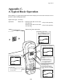
Appendix C: A Typical Basic Operation
Appendix D: Quality Assurance Standards
ii
■ Technical Terms Used in This Manual
Source Program and Object Program (User Program)
Generally, a source program is translated into an object program by a compiler. This
manual calls an object program a user program.
BHT-BASIC
This manual expresses BHT-BASIC3.0 and BHT-BASIC3.5 as BHT-BASIC.
■ Related Publications
BHT-BASIC Programmer's Manual (BHT-100 series)
Transfer Utility Guide
Ir-Transfer Utility C Guide
Ir-Transfer Utility E Guide
■ Screen Indication
The lettering in the screens in this manual is a little different from that in the actual
screens. File names used are only for description purpose, so they will not appear if
you have not set files having those names.
iii
SAFETY PRECAUTIONS
Be sure to observe all these safety precautions.
■ Please READ through this manual carefully. It will enable you to use the BHT and
CU correctly.
■ Always keep this manual nearby for speedy reference.
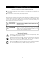
Strict observance of these warning and caution indications are a MUST for preventing
accidents which could result in bodily injury and substantial property damage. Make
sure you fully understand all definitions of these terms and related symbols given
below, before you proceed to the text itself.
WARNING
Alerts you to those conditions which could cause serious bodily injury or death if the instructions are not
followed correctly.
CAUTION
Alerts you to those conditions which could cause minor
bodily injury or substantial property damage if the instructions are not followed correctly.
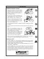
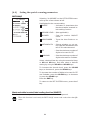
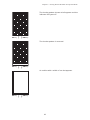
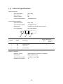
Meaning of Symbols
A triangle (
) with a picture inside alerts you to a warning of danger. Here
you see the warning for electrical shock.
A diagonal line through a circle ( ) alerts you to something you should not
do; it may or may not have a picture inside. Here you see a screwdriver
inside the circle, meaning that you should not disassemble.
A black circle ( ) with a picture inside alerts you to something you MUST
do. This example shows that you MUST unplug the power cord.
iv
WARNING
Handling the battery cartridge
• Never disassemble or heat the battery
cartridge, nor put it into fire or water;
doing so could cause battery-rupture or
leakage of battery fluid, resulting in a
fire or bodily injury.
Never
put me
into fire!
• Do not carry or store the battery cartridge together with metallic ball-point
pens, necklaces, coins, hairpins, etc.
Doing so could short-circuit the terminal pins, causing the batteries to rupture or the battery fluid to leak, resulting in a fire or bodily injury.
Do not
shortcircuit me!
• Avoid dropping the battery cartridge or letting it undergo any shock
or impact.
Doing so could cause the batteries to break, generate heat, rupture or
burn.
• Only use the dedicated charger (CU7001, C-700 or C-750) for charging the
rechargeable battery cartridge.
Using a different type of charger could
cause battery-rupture or leakage of battery fluid and result in a fire, bodily injury, or serious damage to property.
Charge only
with the
dedicated
device.
Undedicated
• Never charge the rechargeable battery cartridge where any inflammable gases may be emitted; doing so could cause fire.
Handling the BHT
• The BHT-100BF uses a laser light for indicating the scanning range.
The intensity of the laser light might be too low to inflict bodily injury.
However, do not look into the laser beam.
The BHT-100BF complies with Laser Safety Standard, Class II of 21
CFR Chapter 1, Subchapter J.
The BHT-100BF does not mount beam attenuator and laser radiation
emission indicator required by this standard. Instead, the softwarecontrolled trigger switches (see Section 2.2 "Components and Functions") function as them because the laser light is not enabled without
the trigger switches pressed.
v
WARNING
• Do not look into the light source through the reading window or point
the light source towards the eyes.
The light emitted through the reading window is harmful to the eyes.
• Do not poke at the eyes with the stylus that comes with the BHT.
Handling the CU
• If smoke, abnormal odors or noises come from the CU, immediately
unplug the AC adapter from the wall socket and contact your nearest
dealer.
Failure to do so could cause fire or electrical shock.
• If foreign material or water gets into the CU, immediately unplug the
AC adapter from the wall socket and contact your nearest dealer.
Failure to do so could cause fire or electrical shock.
• If you drop the CU so as to damage its housing, immediately unplug
the AC adapter from the wall socket and contact your nearest dealer.
Failure to do so could cause fire or electrical shock.
• Never use the CU for charging anything other than the specified
rechargeable battery cartridges.
Doing so could cause heat, battery-rupture, or fire.
• Never bring any metals into contact with the output terminals.
Doing so could produce a large current through the CU, resulting in
heat or fire, as well as damage to the CU.
• Use the dedicated AC adapter only. Failure to do so could result in
fire.
• Never use the CU on the line voltage other than the specified level.
Doing so could cause the CU to break or burn.
• If the power cord of the AC adapter is damaged (e.g., exposed or
broken lead wires), stop using it and contact your nearest dealer.
Failure to do so could result in a fire or electrical shock.
vi
CAUTION
Basic handling tips
I'm burning
up!
• Never put the BHT in places where there
are excessively high temperatures, such
as inside closed-up automobiles, or in
places exposed to direct sunlight.
Doing so could affect the housing or
parts, resulting in a fire.
• Avoid using the BHT in extremely humid or dusty areas, or where there are
drastic temperature changes.
This
humidity
is killing
me!
Moisture or dust will get into the BHT,
resulting in malfunction, fire or electrical shock.
Hothouse
Refrigeration
Refrigeration
I'm
freezing!
Refrigeration
• Never disassemble or modify the BHT; doing so could result in an
accident such as break or fire.
Never
disassemble
Handling the rechargeable battery cartridge
• Never charge a wet or damp rechargeable battery cartridge.
Doing so could cause the batteries to break, generate heat, rupture,
or burn.
Handling the BHT
• If smoke, abnormal odors or noises come from the BHT, immediately
turn off the power, pull out the battery cartridge, and contact your
nearest dealer.
Failure to do so could cause smoke or fire.
• If foreign material or water gets into the
BHT, immediately turn off the power,
pull out the battery cartridge, and contact your nearest dealer.
Failure to do so could cause smoke or
fire.
vii
Keep me
away from
water!
CAUTION
• If you drop the BHT so as to damage its housing, immediately turn off the power, pull out
the rechargeable battery cartridge, and contact your nearest dealer.
Do not
drop
me!
Failure to do so could cause smoke or fire.
• Do not use batteries or power sources other than the specified ones;
doing so could generate heat or cause malfunction.
• In environments where static electricity can build into significant
charges (e.g., if you wipe off the resin plate with a dry cloth), do not
operate the BHT. Doing so will result in malfunction or machine
failure.
• Touch the LCD only with the stylus that comes with the BHT. Using
the tip of a pen or any pointed object will result in a damaged or
broken LCD.
Handling the CU
• If you will not be using the CU for a long time, be sure to unplug the
AC adapter from the wall socket for safety.
Failure to do so could result in a fire.
• When caring for the CU, unplug the AC adapter from the wall socket
for safety.
Failure to do so could result in an electrical shock.
• Never cover or wrap up the CU or AC adapter in a cloth or blanket.
Doing so could cause the unit to heat up inside, deforming its housing, resulting in a fire.
Always use the CU and AC adapter in a well-ventilated area.
• Do not place the CU anyplace where it may be subjected to oily
smoke or steam, e.g., near a cooking range or humidifier.
Doing so could result in a fire or electrical shock.
viii
CAUTION
• Keep the power cord away from any heating equipment.
Failure to do so could melt the sheathing, resulting in a fire or
electrical shock.
• Do not insert or drop foreign materials such as metals or anything
inflammable through the openings or vents into the CU.
Doing so could result in a fire or electrical shock.
■ DENSO WAVE INCORPORATED does not assume any product liability arising out
of, or in connection with, the application or use of any product, circuit, or application
described herein.
■ Intellectual Property Precaution
DENSO WAVE INCORPORATED ("DENSO WAVE") takes reasonable precautions to
ensure its products do not infringe upon any patent of other intellectual property
rights of other(s), but DENSO WAVE cannot be responsible for any patent or other
intellectual property right infringement(s) or violation(s) which arise from (i) the
use of DENSO WAVE's product(s) in connection or in combination with other
component(s), product(s), data processing system(s) or equipment or software not
supplied from DENSO WAVE; (ii) the use of DENSO WAVE's products in a manner
for which the same were not intended nor designed; or (iii) any modification of
DENSO WAVE's products by other(s) than DENSO WAVE.
Licensed under one or more of the following U.S. patents:
4, 570, 057;
5, 081, 343;
5, 187, 355;
5, 288, 985
4, 766, 300;
5, 095, 197;
5, 187, 356;
4, 894, 523;
5, 144, 119;
5, 218, 191;
5, 021, 642;
5, 144, 121;
5, 233, 172;
ix
5, 038, 024
5, 182, 441
5, 258, 606
■ Proper Care of the BHT and CU
Clean the housings, battery cartridge terminals, and CU-7001 charge terminals with a
dry, soft cloth. Before cleaning, be sure to turn the BHT power off and unplug the AC
adapter of the CU.
•
•
•
•
Never use benzene, alcohol, or other organic solvents. The housing may be
marred or the paint may come off.
Never rub or strike the liquid crystal display (LCD) with anything hard. The LCD
surface will be easily scratched or broken.
When cleaning the keypad, do not scrub
the surface too hard, and do not pull on
the keys. Doing so may break the keys
or cause the keypad to dislocate.
Take care of me
with a dry soft
cloth.
NO WAY!!
Thinner Benzine
If the BHT or CU becomes smudged, moisten a soft cloth with neutral detergent and
wring it out thoroughly. Wipe the BHT or CU with the cloth and then go over it
again with a dry cloth.
Dust or dirt accumulating on the clear plate of the reading window will affect reading
performance. If you use the BHT in dusty areas, therefore, periodically check the clear
plate of the reading window and clean it if dusty.
•
To clean the plate, first blow the dust away with an air brush. Then wipe the plate
with a cotton swab or the similar soft one gently.
•
If sand or hard particles have accumulated, never rub the plate; doing so will
scratch or damage it. Blow the particles away with an air brush or a soft brush.
x
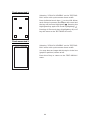
Labeling
*
*Only for the BHT-100BF.
xi
Content Overviews
Preface ................................................................................................................................. i
How this book is organized .............................................................................................. ii
SAFETY PRECAUTIONS ..................................................................................................... iv
Chapter 1
1.1
Quick Guide ................................................................................................. 1
Reading 2D Codes and Bar Codes ........................................................................... 2
BHT-100QF ................................................................................................................. 2
BHT-100BF .................................................................................................................. 4
1.2
Setting and Using the Hand Strap and Stylus ........................................................ 6
1.3
Setting the Backlight ................................................................................................. 8
1.4
Using the Keypad ...................................................................................................... 9
1.5
Transferring Data ....................................................................................................... 10
Chapter 2
Getting Started the BHT and System Mode ............................................. 13
2.1
BHT System Configuration ....................................................................................... 14
2.2
Components and Functions ..................................................................................... 19
2.3
Preparation ................................................................................................................ 21
2.3.1 Setting-up 1: Loading the Battery Cartridge ................................................... 21
2.3.2 Setting-up 2: Setting the Calendar Clock ........................................................ 25
2.3.3 Adjusting the LCD Contrast, Beeper Volume and Touch Screen,
and Switching the Beeper & Vibrator .............................................................. 26
2.3.4 Battery Voltage Display ..................................................................................... 30
2.3.5 Synchronization Display in Radio Communication ........................................ 30
2.3.6 Battery Replacement Notes .............................................................................. 31
2.3.7 BHT Turning-off Notes ...................................................................................... 33
2.4
Initializing the BHT System ...................................................................................... 37
2.5
Operating in System Mode ...................................................................................... 41
2.5.1 Starting System Mode ...................................................................................... 41
2.5.2 Operating in System Mode .............................................................................. 45
2.5.3 Detailed Description of the Functions in System Mode ................................. 47
Chapter 3
3.1
Communications Operations of the BHT-100QF/100BF .......................... 125
Spread Spectrum Communication .......................................................................... 126
3.1.1 Notes for Wireless Operations ......................................................................... 126
3.1.2 Domains and Security IDs ................................................................................ 126
3.2
Infrared Communication .......................................................................................... 128
xii
3.3
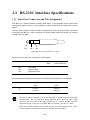
RS-232C Interface Specifications ............................................................................. 130
3.4
Basic Communications Specifications and Parameters ........................................ 132
3.4.1 Basic Communications Specifications ............................................................ 132
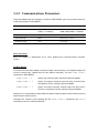
3.4.2 Communications Parameters ........................................................................... 134
3.5
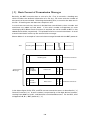
Communications Protocols ...................................................................................... 135
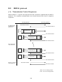
3.5.1 BHT-protocol ...................................................................................................... 135
3.5.2 BHT-Ir Protocol .................................................................................................. 141
Chapter 4
Error Messages ............................................................................................ 147
4.1
System Errors ............................................................................................................ 148
4.2
Errors in System Mode ............................................................................................. 153
Chapter 5
Handling the CU-7000 (Option) ................................................................. 159
5.1
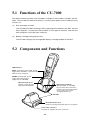
Functions of the CU-7000 ......................................................................................... 160
5.2
Components and Functions ..................................................................................... 160
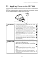
5.3
Applying Power to the CU-7000 ............................................................................... 161
5.4
Communicating with the Host Computer ............................................................... 162
5.4.1 Setting the Transmission Speed of the CU-7000 ............................................ 162
5.4.2 Interface Cable Connection .............................................................................. 162
5.4.3 Interfacing with the Host Computer ................................................................ 163
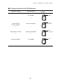
5.5
Charging the Rechargeable Battery Cartridge (using the CU-7001) ..................... 164
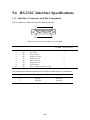
5.6
RS-232C Interface Specifications ............................................................................. 166
Appendices
...................................................................................................................... 169
Appendix A. Specifications ............................................................................................... 170
A.1
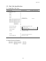
BHT-100QF ......................................................................................................... 170
A.2
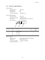
BHT-100BF .......................................................................................................... 177
A.3
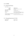
CU-7000 .............................................................................................................. 182
Appendix B. Communications Protocol Details ............................................................... 184
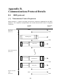
B.1
BHT-protocol ...................................................................................................... 184
B.2
BHT-Ir protocol .................................................................................................. 194
Appendix C. A Typical Basic Operation ............................................................................ 205
Appendix D. Quality Assurance Standards ...................................................................... 206
D.1
Applicable Standards ........................................................................................ 206
D.2
Interface Cables ................................................................................................. 207
Index ..................................................................................................................................... 209
xiii
Chapter 1. Quick Guide
Chapter 2. Getting Started the BHT
and System Mode
Chapter 3. Communications Operations
of the BHT-100QF/100BF
Chapter 4. Error Messages
Chapter 5. Handling the CU-7000 (Option)
Appendices
Chapter 1. Quick Guide
Chapter 1
Quick Guide
This chapter describes the basic operating method of the BHT and the related notes.
1.1
Reading 2D Codes and Bar Codes ............................................................................ 2
BHT-100QF ............................................................................................................... 2
BHT-100BF ............................................................................................................... 4
1.2
Setting and Using the Hand Strap and Stylus ........................................................ 6
1.3
Setting the Backlight ................................................................................................. 8
1.4
Using the Keypad ...................................................................................................... 9
1.5
Transferring Data ..................................................................................................... 10
1
1.1 Reading 2D Codes and Bar Codes
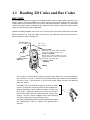
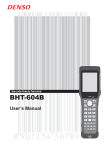
BHT-100QF
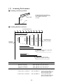
Turn the BHT power on, bring the reading window to the target code, and press the
trigger switch. The BHT-100QF turns three marker LEDs on to indicate the scanning
range and the illumination LED to scan the code. Keep the BHT stationary in a position
where the target code lies between the right and left markers and the center marker
comes to the center of the target code.
Hold the reading window 4 to 14 cm (1.6 to 5.5 inches) away from codes to be scanned.
When the BHT has read the code successfully, the indicator LED will illuminate in
green and the markers will go off.
4 to 14 cm
(1.6" to 5.5")
Markers
Trigger switch
(M3 key)
Indicator LED
Illuminates in green when the BHT
has successfully read the code.
Touch screen LCD
Shows the scanned image of a code
lying inside the scanner’s view if the
view finder is set to ON.
Trigger switch
(M4 key)
PW key
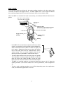
• The markers show the left-to-right scanning range. When the scanning distance
is 8.5 to 9.5 cm (3.3 to 3.7 inches), they indicate almost the center of the up-down
scanner’s view. If the distance is out of the range, those markers will deviate
from the center.
• If the BHT fails to read due to specular effects or other
factors, change the scanning angle of the reading window or the distance from codes as shown at right, and
try it again. (Specular effects occur when the reflection of the light from the code becomes excessively
strong. This can easily happen when the reflecting
surface is polished or covered with vinyl.)
• The code reading procedure may differ depending upon
the application used, so follow the application's
manual.
2
Chapter 1. Quick Guide
• Before reading 2D codes or bar codes, clean those labels if stained.
• Avoid using the BHT in direct sunlight. The BHT might fail to read correctly.
• To read 2D codes or bar codes on curved surfaces, apply the BHT to the target
code so that the code comes to the center of the scanning range indicated by the
markers.
• Depending upon the code size or cell pitch, the proper scanning distance from
2D codes or bar codes will differ.
• Do not use the BHT in the vicinity of radio equipment. The BHT may malfunction.
At the scanning time, the marker LEDs and illumination LED will come on. The
illumination LED may not come on where it is bright enough for the BHT to
scan. The light intensity of those LEDs will vary depending upon the scanning
conditions and variation of their elements.
3
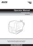
BHT-100BF
Turn the BHT power on, bring the bar-code reading window to the bar code to be
scanned, and press the trigger switch. The BHT-100BF emits a laser light to indicate
the scanning range and turns on the illumination LED to scan the bar code.
When the BHT has read the bar code successfully, the indicator LED will illuminate in
green.
Bar code scanning range
covered by the laser light
Max. 40 cm
(15.7")*
Indicator LED
Illuminates in green when the BHT
has successfully read the code.
Touch screen LCD
Trigger switch
(M3 key)
Trigger switch
(M4 key)
PW key
• If the BHT fails to read due to specular effects or other
factors, change the scanning angle of the reading window or the distance from codes as shown at right, and
try it again. (Specular effects occur when the reflection of the light from the bar code becomes excessively strong. This can easily happen when the reflecting surface is polished or covered with vinyl.)
• The laser light indicates the scanning range as a guide.
The indicated scanning range will deviate a little bit
from the actual one. Keep the BHT so that the laser
light comes to almost the center of the bar code height.
• The BHT can read bar codes at a maximum distance of 40 cm (15.7")* from the
reading window. (*For details about the scanning conditions, refer to Appendix
A.)
• The bar code reading procedure may differ depending upon the application
used, so follow the application's manual.
4
Chapter 1. Quick Guide
• Before reading bar codes, clean those labels if stained.
• Avoid using the BHT in direct sunlight. The BHT might fail to read correctly.
• To read bar codes on curved surfaces, apply the BHT to the target bar code so that the
code comes to the center of the scanning range indicated by the laser beam.
• When you pull the bar-code reading window away from bar codes, the actual
scanning range will become narrower than the range covered by the laser beam.
• Do not use the BHT in the vicinity of personal or amateur radio equipment. The
BHT may malfunction.
The light intensity of the laser light or illumination LED will vary depending
upon the scanning conditions and variation of their elements.
5
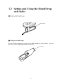
1.2 Setting and Using the Hand Strap
and Stylus
■ Setting the hand strap
Hand strap
■ Using the hand strap
Put your hand through the hand strap and hold the BHT as shown below. This will
prevent you from dropping the BHT accidentally.
Hand strap
6
Chapter 1. Quick Guide
■ Setting the stylus
Hand strap
Stylus
■ Using the stylus
The BHT has a touch screen LCD that enables you to use touch keys and draw images
on the touch screen with the stylus if you have defined those touch keys and graphics
pad box in user programs, respectively. Before using the touch screen, adjust it,
referring to Subsection 2.3.3.
Press the touch screen only with the stylus that comes with the BHT. Using the tip
of a pen or any pointed object will result in a damaged or broken LCD. Strong
pressure or impact applied to the LCD may also break the LCD.
7
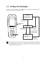
1.3 Setting the Backlight
Pressing the right-hand trigger switch (M4 key) while holding down the SF (Shift) key
activates or deactivates the backlight function.
Backlight OFF
(The backlight function
is OFF when you turn
the BHT power on.)
Press the right-hand
trigger switch while
holding down SF.
Right-hand
trigger switch
(M4)
Backlight ON
M1
M2
7 ABC
8 DEF
9 GHI
4 JKL
5MNO
6 PQR
1STU
2 VWX
3 YZ
+
0 -%$
,/
BS
Press any key (except for
the simultaneous depression of the right-hand
trigger switch and SF).
ENT
SP
C
Press the righthand trigger
switch while
holding down SF.
If no key is
pressed for at
least 3 seconds.
SF
PW
SF
Backlight OFF
(The backlight function
is kept ON.)
Press the righthand trigger
switch while
holding down SF.
In user programs, you can select the key to be used for activating or deactivating
the backlight function (instead of the initial setting: combination of SF and the
right-hand trigger switch), as well as modifying the ON-duration of the backlight
before the automatic turning-off.
8
Chapter 1. Quick Guide
1.4 Using the Keypad
■ Entering Numerical Data
To enter numerical data, e.g., the quantity of goods, use the ten numerical keys and
the ENT key.
For example, to enter the number "120," press the 1, 2 and 0 keys and then press
the ENT key.
If you key in any wrong value, press the C or BS key and then enter the correct one.
■ Selecting Tasks
If the LCD shows the selection items (xxx) prefixed by numerals (e.g., 1: xxx, 2: xxx),
use the numerical keys to select a desired item and press the ENT key to execute.
If a YES/NO screen (e.g., 1: YES, 2: NO) appears, press the 1 key for YES response and
2 key for NO response.
■ Entering Alphabetic Characters
The BHT supports the alphabet entry function which allows you to enter alphabetic
characters, space, and symbols from the keypad during execution of a user program.
For the alphabet entry procedure, refer to the "BHT-BASIC Programmer's Manual
(BHT-100 series)."
9
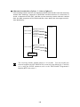
1.5 Transferring Data
■ Using radio link
Using radio waves, the BHT may transfer data to an access point in a spread spectrum
communications system.
If there are too many communications errors, first make sure that the BHT points
directly at an access point because the 2.4-GHz band requires a more or less
straight line path.
Host computer
Access point
Built-in antenna
For data transfer using radio link, it is necessary to configure a wireless local area
network (wireless LAN) connecting the BHT and access points.
10
Chapter 1. Quick Guide
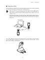
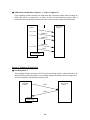
■ Using infrared link
Using infrared rays, the BHT may transfer data directly to the host computer equipped
with an IrDA interface port and other IrDA-compliant devices.
• Make sure that there is no obstruction in the light path between the BHT and any
target stations. In infrared communication, you need to keep the BHT and any
target stations within the effective infrared radiation range, usually 10 to 80 cm
(3.94 to 31.50").
• Shield the IrDA interface from direct sunlight, ambient intense lighting (inverterdriven fluorescent lighting, in particular), and other potential sources of infrared
radiation. Sources to watch out for include remote control units for television sets
and the like.
Host computer
M1
M2
7 ABC
8 DEF
9 GHI
4 JKL
5MNO
6 PQR
1STU
2 VWX
3 YZ
+
,/
0
BS
ENT
SP
C
SF
PW
BHT
BS
0
C
SF
SP
,/
2 VWX
1STU
5MNO
4 JKL
8 DEF
7 ABC
M1
PW
ENT
3 YZ
+
6 PQR
9 GHI
M2
BHT
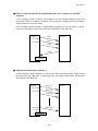
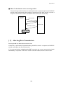
For a host computer having no IrDA interface port, use the optical communications
unit CU-7000 (option) connected to the host via an RS-232C interface cable. Put the
BHT in the CU-7000 as shown below.
11
12
Chapter 2. Getting Started the BHT and System Mode
Chapter 2
Getting Started the BHT
and System Mode
This chapter summarizes the BHT system configuration and describes the operation
including preparation and System Mode (which is required for the efficient use of
application programs).
2.1
2.2
2.3
BHT System Configuration ................................................................................................ 14
Components and Functions ............................................................................................... 19
Preparation .......................................................................................................................... 21
2.3.1 Setting-up 1: Loading the Battery Cartridge ............................................................ 21
2.3.2 Setting-up 2: Setting the Calendar Clock .................................................................. 25
2.3.3 Adjusting the LCD Contrast, Beeper Volume and Touch Screen, and
Switching the Beeper & Vibrator ............................................................................... 26
2.3.4 Battery Voltage Display .............................................................................................. 30
2.3.5 Synchronization Display in Radio Communication ................................................. 30
2.3.6 Battery Replacement Notes ....................................................................................... 31
2.3.7 BHT Turning-off Notes ............................................................................................... 33
[1]
"Shutdown in progress" message ..................................................................... 33
[2]
If the BHT is turned off abnormally ................................................................... 33
[3]
About "$$BRKLST.SYS" ...................................................................................... 36
[4]
If invalid files are found ...................................................................................... 36
2.4
Initializing the BHT System ................................................................................................ 37
2.5
Operating in System Mode ................................................................................................ 41
2.5.1 Starting System Mode ............................................................................................... 41
2.5.2 Operating in System Mode ........................................................................................ 45
[1]
Calling up the desired set screen ...................................................................... 45
[2]
Selecting a desired setting ................................................................................. 46
2.5.3 Detailed Description of the Functions in System Mode .......................................... 47
[1]
Program Execution ............................................................................................. 47
[2]
Downloading ....................................................................................................... 49
[3]
Uploading ............................................................................................................ 53
[4]
System Environment Setting ............................................................................. 56
[5]
Testing ................................................................................................................. 80
[6]
System Information .......................................................................................... 101
[7]
Downloading/Uploading by FTP ..................................................................... 102
[8]
RF Menu ............................................................................................................ 107
[9]
Deleting Files ..................................................................................................... 110
[ 10 ] Downloading/Uploading the BHT System Parameter File ............................ 112
[ 11 ] Setting the Remote Wakeup ............................................................................ 118
[ 12 ] Downloading/Uploading the System Message File ....................................... 119
13
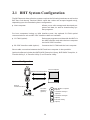
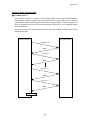
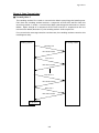
2.1 BHT System Configuration
The BHT barcode data collection system requires the following hardware as well as the
BHT Bar Code Handy Terminal (which reads bar codes and accepts keypad entry),
depending upon the intended system configuration.
●
Host computer:
Allows you to edit, manage and download programs and data, as well as downloading system programs.
For host computers having no IrDA interface ports, the optional CU-7000 optical
communications unit and RS-232C interface cable are available.
●
CU-7000 (option):
Exchanges programs and data with the BHT via
the IrDA interface and with the host computer
via the RS-232C interface.
●
RS-232C interface cable (option):
Connects the CU-7000 and the host computer.
Direct cable connection between the BHT and host computer is also possible.
Optional software includes the BHT-BASIC Extension Library, BHT-BASIC Compiler, IrTransfer Utility C, Ir-Transfer Utility E, and Transfer Utility.
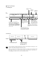
System Configuration
BHT
Host Computer
Optical Communications
M1
M2
7 ABC
8 DEF
9 GHI
4 JKL
5MNO
6 PQR
1STU
2 VWX
3 YZ
+
,/
0
BS
C
ENT
SF
PW
RS-232C Interface
Optical
Communications
RS-232C
Interface
(option)
CU-7000 (option)
BHT-BASIC Compiler
(option)
Ir-Transfer Utility C
(option)
Ir-Transfer Utility E
(option)
Transfer Utility
(option)
14
Chapter 2. Getting Started the BHT and System Mode
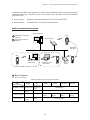
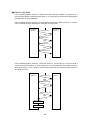
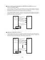
In addition, the BHT may operate in a radio communications system (spread spectrum
communication) by connecting with access points by a wireless local area network
(wireless LAN).
●
Access point:
Wireless communications base unit for the BHT-100
●
Ethernet port:
Connects the access points and Ethernet
Radio communications system
Host computer
BHT-BASIC Compiler
(option)
BHT
Access point
Ir-Transfer Utility E
(option)
Roaming
function
Ethernet 10BASE-T
BHT
Wireless board
connection
Wireless card
connection
Access
point
BHT
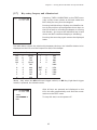
■ Host Computer
Models: PC/AT, PS/2
Optional application programs and OSes
OS
MS-DOS
Win3.1
Win95
Win98
WinNT3.5/4.0
Applications
BHT-BASIC3.0 BHT-BASIC3.0
BHT-BASIC Compiler (MS-DOS–based) (Windows3.1based)
MS-DOS–
—
Ir-Transfer Utility C
based
Ir-Transfer Utility E
—
—
Transfer Utility
MS-DOS–
based
Windows3.1–
based
Win2000
Professional
BHT-BASIC3.5
Win95-/NT-based
Win95-/NTbased
Win95-/NTbased*
Win95-/NTbased
Win95-/NT-based
*This application does not activate any built-in port.
15
Win95-/NTbased*
■ CU-7000 and RS-232C Interface Cable (option)
The CU-7000 is an IrDA-compliant communications unit which is required when your
host computer is not equipped with an IrDA interface port. The CU-7000 exchanges
data and programs with the BHT optically, and with the host computer via the RS-232C
interface cable.
You may directly connect two BHTs with each other by using a commercially available
metal cable having 3-pole mini stereo plugs (as a direct-connect interface cable). You
also connect the BHT directly with the host computer or with the modem by using the
direct-connect interface cable compatible with the target equipment. (NOTE: The
direct-connect interface port of the BHT is not designed to stand frequent connecting/
disconnecting. You are, therefore, recommended to use the CU-7000 where you
expect to do a lot of connecting and disconnecting of the BHT to/from a host computer.)
■ BHT-BASIC Compiler (option)
This Compiler compiles a source program written in BHT-BASIC by an editor of the
host computer running the MS-DOS, into the object program (user program) which
can be used in the BHT. The compiled and linked program file is named "XXX.PD3."
(XXX: File name you can set arbitrarily under the MS-DOS rules) You should download
it to the BHT by using Ir-Transfer Utility C/Ir-Transfer Utility E/Transfer Utility.
■ Ir-Transfer Utility C (option)
Running on the host computer, this utility transfers files between the BHT and the host
computer. For its file transfer control procedure, the utility uses the BHT-Ir protocol.
(For the details about the BHT-Ir protocol, refer to Chapter 3, Subsection 3.5.2.)
To transfer files under any of the following conditions, use Ir-Transfer Utility C:
-
At transmission speeds of 115200 or 57600 bps (This may be impossible depending upon the host computer type.)
-
When the BHT is placed on the CU-7000
-
Via the direct-connect interface of the BHT
■ Ir-Transfer Utility E (option)
Running on the host computer, this utility transfers files between the BHT and the host
computer. For its file transfer control procedure, the utility uses the BHT-Ir protocol.
(For the details about the BHT-Ir protocol, refer to Chapter 3, Subsection 3.5.2.)
To transfer files under any of the following conditions, use Ir-Transfer Utility E:
-
Via an external IR transceiver
-
Via an IR port integrated in a computer
16
Chapter 2. Getting Started the BHT and System Mode
■ Transfer Utility (option)
Running on the host computer, this utility transfers files between the BHT and the host
computer. For its file transfer control procedure, the utility uses the BHT-protocol.
(For the details about the BHT-protocol, refer to Chapter 3, Subsection 3.5.1.)
To transfer files under any of the following conditions, use Transfer Utility:
-
When the BHT is placed on the CU-7000
-
Via the direct-connect interface of the BHT
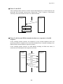
Software Structure
System Programs and JIS Level 1 & Level 2 fonts are resident in the system area and
user area, respectively.
To use extension programs and user programs, you should download the program
files into the user area.
To use data files (e.g., goods master files) required for execution of user programs,
you should download those data files before execution of user programs. Those files
will be stored in the user area.
System
Programs
JIS Level 1
& Level 2
font files
User programs
Program
files
User Area
⇔
System Area
Data
files
Host Computer
■ System Programs
The system programs include the following three sets of programs:
Drivers
Drivers is a set of programs that directly controls the BHT hardware. It may be called
up by the BHT-BASIC Interpreter or System Mode.
BHT-BASIC Interpreter
The interpreter interprets and executes instructions in user programs written in BHTBASIC.
17
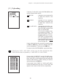
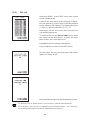
System Mode
System Mode is a system program exclusively designed for the effective use of user
programs in the BHT. It sets up the execution environments for those programs; e.g.,
it prepares downloading/uploading conditions, sets the calendar clock, and tests the
BHT components including the LCD, beeper, and keypad. Shown below is the System
Mode menu (SYSTEM MENU).
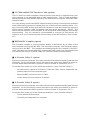
■ JIS Level 1 and Level 2 Font Files
These files contain font data required for displaying Kanji characters on the LCD.
The BHT can display the Kanji characters not only in the conventional standard-size
font (16 dots wide by 16 dots high) but also in the small-size font (12 dots wide by 12
dots high) in application programs. It can also display the double-width, doubleheight, and quadruple-size (double-width & -height) Kanji characters of those 16-dot
and 12-dot fonts in application programs.
If you do not need to display Kanji characters, you may delete these JIS font files.
After deletion, the memory area which was occupied by these files can be used as a
user area. For the deleting procedure, refer to Section 2.4, "Initializing the BHT
System" or Subsection 2.5.3, "[ 9 ] Deleting Files."
The names of the JIS font files are:
FNT16J1.FN3
FNT16J2.FN3
FNT12J1.FN3
FNT12J2.FN3
(JIS Level 1 font, 16-dot)
(JIS Level 2 font, 16-dot)
(JIS Level 1 font, 12-dot)
(JIS Level 2 font, 12-dot)
■ User Programs
You can develop application programs to meet individual job requirements by using
the BHT-BASIC Compiler.
To download those user programs to the BHT, use Ir-
Transfer Utility C/Ir-Transfer Utility E/Transfer Utility.
18
Chapter 2. Getting Started the BHT and System Mode
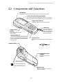
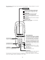
2.2 Components and Functions
Indicator LED
Illuminates in green when the BHT has successfully read a code.
Touch screen LCD (liquid crystal display)
Shows the characters and graphic patterns. You may
directly touch the display with the stylus for data entry.
Trigger switch (M4 key)
Press this switch to start code reading.
Hand strap
Be sure to put your
hand through this
strap to prevent you
from dropping the
BHT accidentally.
Trigger switch
(M3 key)
Press this switch to start
code reading.
Optical interface port
Used to exchange data/programs with
the host computer via its integrated IR
port or via the optical communication
unit CU-7000.
Connector cover
Inside this cover is the direct-connect interface
port.
Reading window
Stylus
Rechargeable battery
cartridge
Main power source of
the BHT.
Built-in antenna
Do not cover this antenna section with metal-evaporated
tape or by hand. Doing so may
result in communications failures.
Release button
Press this button to remove the
battery cartridge.
19
The functions of the keys may be set by user programs. Shown below is a set of
sample functions.
Status Indicators
Battery voltage level
Shows the current battery voltage level.
Displays when the voltage level is high.
Displays when the voltage level is low.
Keypad shift state
Displays when the keypad is shifted.
Alphabet and touch screen input states
Displays when the alphabet input function
is activated.
Displays when the touch screen is ready to
accept entry.
Synchronization state
Displays when the BHT is synchronized
with an access point.
M1
Numerical keys
Used for numerical input.
M2
7 ABC
8 DEF
9 GHI
4
JKL
5
6 PQR
1
STU
2
BS
VWX
,/
0 -%$
BS (Backspace) key
Moves back one character.
MNO
ENT
SP
C
3 YZ
+
SF
PW
M1/M2 (Magic) keys
Up- and down-arrow keys are assigned
to the M1 and M2 keys by default,
respectively. If the SF key is held down,
left- and right-arrow keys are assigned
to the M1 and M2 keys, respectively.
These keys may be used as an SF key,
ENT key, or backlight function on/off
key depending upon definition in System Mode or in user programs. They
may be also assigned string data in
user programs.
ENT (Enter) key
Finalizes the inputted data or operations, and starts the corresponding
processing.
C (Clear) key
Clears the last inputted data or
returns to the original screen.
PW (Power) key
Turns the BHT on or off.
SF (Shift) key
Used in combination with numerical
keys for special input procedures.
Function keys F1 through F8 may be assigned to FUNC keys defined on the touch
screen. (For details, refer to Subsection 2.5.3, [4.6].)
20
Chapter 2. Getting Started the BHT and System Mode
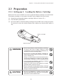
2.3 Preparation
2.3.1 Setting-up 1: Loading the Battery Cartridge
Before the first use of the BHT, be sure to load the battery cartridge as shown below.
The battery cartridge is not loaded in the BHT when shipped from the factory.
(1)
Charge the rechargeable battery cartridge. (Refer to Section 5.5.)
(2)
Turn the BHT upside down.
(3)
As shown below, slide the battery cartridge into the BHT until it clicks into place.
(To remove it, press the release button after making sure that the BHT power is
off.)
Battery cartridge
Release button
WARNING
• Never disassemble or heat the battery cartridge,
nor put it into fire or water; doing so could
cause battery-rupture or leakage of battery fluid,
resulting in a fire or bodily injury.
• Do not carry or store the battery cartridge together with metallic ball-point pens, necklaces,
coins, hairpins, etc.
Doing so could short-circuit the terminal pins,
causing the batteries to rupture or the battery
fluid to leak, resulting in a fire or bodily injury.
• Avoid dropping the battery cartridge or letting
it undergo any shock or impact.
Doing so could cause the batteries to break,
generate heat, rupture or burn.
• Never charge the rechargeable battery cartridge
where any inflammable gases may be emitted;
doing so could cause fire.
CAUTION
• Do not use batteries or power sources other
than the specified ones; doing so could generate heat or cause malfunction.
21
• The BHT has an integrated backup power source which backs up the memory and
calendar clock in the BHT when no battery cartridge is loaded or the voltage level
of the battery cartridge drops below the specified level. The backup power source
is automatically charged by the battery cartridge.
When you first load the battery cartridge after purchase or you load it after leaving
the BHT unused for a long time, do not remove the battery cartridge for 10
minutes or more after that loading. This is for charging the memory backup
source integrated in the BHT.
• Be sure to turn the BHT off before battery replacement. Replace the battery
cartridge quickly. Load a charged battery cartridge within 3 minutes from the
removal of the cartridge to avoid data loss.
After battery replacement, turn the BHT on and check its operation.
• If you leave the BHT with no battery cartridge loaded for a long time, the memory
contents will no longer be backed up so that the message "Contact your administrator. Note the error number. (XXXX)" or "Set the current date and time." may
appear on the LCD.
If you will not be using the BHT for a long time, follow the instructions given in
Subsection 2.3.6, "Battery Replacement Notes."
• Avoid storing the rechargeable battery cartridge in a hot place. The battery
capacity may be decreased.
• Do not touch the charge terminals of the rechargeable battery cartridge or stain
those terminals. Doing so could result in a charging failure.
■ Battery Voltage Level on the Status Indicator Line
The battery voltage level is always displayed on the status indicator line.
(For details, refer to Subsection 2.3.4 "Battery Voltage Display.")
22
Chapter 2. Getting Started the BHT and System Mode
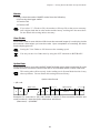
■ Low Battery Indication
Low battery indication—Level 1
If the battery output voltage drops below a specified lower level limit while the BHT is
in operation, the BHT displays the following Level 1 message for approx. 2 seconds
and beeps three times. After that, it will resume previous regular operation.
The battery recharge or replacement time will come soon. Recharge or replace the
battery cartridge as soon as possible.
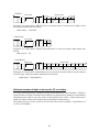
Low battery indication—Level 2
If you continue to use the BHT without recharge or battery replacement after the Level
1 message appears, the BHT displays the following Level 2 message, beeps five times,
and then turns itself off. Depending upon the battery level, the beeper may not sound
five times.
Recharge or replace the battery cartridge.
23
• You may charge the rechargeable battery cartridge with the optional CU-7001
communication unit or optional C-700/C-750 charger. For the charging procedure using the CU-7001, refer to Chapter 5. For that using the C-700/C-750, refer
to the "C-700 User's Manual"/"C-750 User's Manual."
• If the "Charge the battery!" message appears after the BHT undergoes any shock
or impact, turn the power off and on and then check the battery output level. The
battery may not have run out.
WARNING
Only use the dedicated charger (CU-7001, C-700
or C-750) for charging the rechargeable battery
cartridge.
Using a different type of charger could cause
battery-rupture or leakage of battery fluid and
result in a fire, bodily injury, or serious damage
to property.
CAUTION
Never charge a wet or damp rechargeable battery cartridge.
Doing so could cause the batteries to break, generate heat, rupture or burn.
24
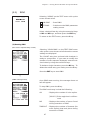
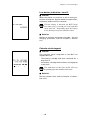
Chapter 2. Getting Started the BHT and System Mode
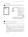
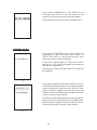
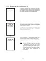
2.3.2 Setting-up 2: Setting the Calendar Clock
Turn the BHT on by pressing the PW key.
The following message will appear.
In the following cases, the above message will appear. In such instances, it is
necessary to set the date and time. (The indication "00/01/01 00:00" will differ
depending upon the calendar clock state.)
• The BHT is first turned on from the time of purchase.
• The BHT is turned on after the memory backup power source is completely discharged.
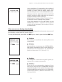
Use the numerical keys to enter the year (only the
last two digits), month, day, hour, and minute in
this order. If the data is in one digit, add a 0 (zero)
preceding the data.
For the year, be sure to enter the last two
digits of the year. For the hour, enter it in the
24-hour format.
If any of the year, month, day, hour, and
minute is not entered, the ENT key will be
deactivated.
If you make a wrong entry, press the BS key to
delete it and then enter the correct data.
[Example] To set 2001, April 19, at 4:00 p.m.
Press 0, 1, 0, 4, 1, 9, 1, 6, 0, and 0. Then press the
ENT key to register the new setting.
If the above screen does not appear, follow the calendar clock setting procedure given
in Subsection 2.5.3, [4.3] to set the calendar clock.
25
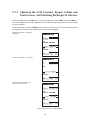
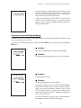
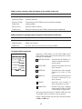
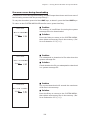
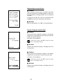
2.3.3 Adjusting the LCD Contrast, Beeper Volume and
Touch Screen, and Switching the Beeper & Vibrator
While holding down the M1 key or right-hand trigger switch (M4), press the PW key.
The main adjustment screen appears which differs depending upon the current state
as shown below.
After adjustment, press the ENT key or no keys for five seconds. The new settings will
be registered and the main adjustment screen will disappear.
When the beeper is selected
(default)
When the vibrator is selected
When both the beeper and
vibrator are selected
(The current selection is highlighted.)
26
Chapter 2. Getting Started the BHT and System Mode
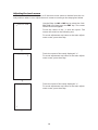
Adjusting the LCD contrast
You can adjust the LCD contrast to eight levels.
(1) Use the 1 key (or M1 or M2 key) to select the LCD CONTRAST line.
(2) To make the contrast low, press the M1 key with the SF key held down; to make it
high, press the M2 key with the SF key held down.
Switching the beeper & vibrator
You may choose any of three ways—beeping only, vibrating only, or beeping & vibrating as a confirmation of completion of code reading.
(1) Use the 2 key (or M1 or M2 key) to select the BEEPER VIBRATION line that will be
SF + M2
SF + M2
SF + M1
SF + M1
highlighted in any one of the following three states:
(2) Highlight the desired way(s) by using the M1 or M2 key while holding down the SF
key.
Adjusting the beeper volume
You can adjust the beeper volume to four levels from OFF to MAX.
(1) Use the 3 key (or M1 or M2 key) to select the BEEPER VOLUME line.
(2) To turn down the volume, press the M1 key with the SF key held down; to turn it
up, press the M2 key with the SF key held down.
Adjusting the beeper volume to be sounded when you press the touch screen
You can adjust the volume of the beeper to be sounded when you press the touch
screen, to three levels from OFF to MAX.
(1) Use the 4 key (or M1 or M2 key) to select the VOLUME line.
(2) To turn down the volume, press the M1 key with the SF key held down; to turn it
up, press the M2 key with the SF key held down.
27
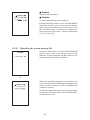
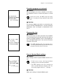
Adjusting the touch screen
At the first use of the touch screen or if the touch areas seem to deviate from the normal positions when in use, adjust the touch screen according to the steps given below.
Use the 5 key (or M1 or M2 key) to select the CALIBRATION line, then press the ENT key. The screen
shown at left will appear.
Touch the center of the "+" with the stylus. The
screen will switch to the following one.
To cancel adjustment and return to the main adjustment screen, press the C key.
⇓
Touch the center of the newly displayed "+."
To cancel adjustment and return to the main adjustment screen, press the C key.
⇓
Touch the center of the newly displayed "+."
To cancel adjustment and return to the main adjustment screen, press the C key.
28
Chapter 2. Getting Started the BHT and System Mode
Touch the center of the 4th "+."
The adjustment will complete and the display will
return to the main adjustment screen.
If the adjustment is not completed normally, the
screen shown at left will appear where you may
choose retry or not.
If you select "1:Yes" and press the ENT key, the display will return to the top screen of the touch
screen adjustment sequence.
If you select "2:No" and press the ENT, or press the
C key, the display will return to the main adjustment screen.
29
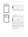
2.3.4 Battery Voltage Display
The battery voltage level is always displayed on the status indicator line (bottom line).
Battery voltage level
Shows the current battery voltage level.
Displays when the voltage level is high.
Displays when the voltage level is low.
Status Indicators
The displayed battery level shows the terminal voltage of the battery, not how
much power is left.
The battery voltage level varies depending upon the operation of the BHT, so the
displayed level also may vary.
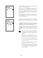
2.3.5 Synchronization Display in Radio Communication
When the BHT is synchronized with an access point during radio communication
(spread spectrum communication), a synchronization icon appears on the LCD as
shown below.
The synchronization display indicates that
the radio link is established but does not assure you that there will be few communications errors.
Indicates that the BHT is
synchronized with an
access point.
30
Chapter 2. Getting Started the BHT and System Mode
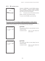
2.3.6 Battery Replacement Notes
■ When is battery replacement needed?
If the "Charge the battery!" appears on the LCD, replace the battery cartridge with a
fully charged one.
If you leave the BHT without replacing the battery cartridge, then the integrated
calendar clock or data will no longer be backed up so that the calendar clock will stop
or the message "Contact your administrator. Note the error number. (XXXX)" will
appear on the LCD.
Be sure to turn the BHT off before battery replacement.
Replace the battery cartridge quickly. Load a charged battery cartridge within 3
minutes after the removal to avoid data loss.
After battery replacement, turn the BHT on and check its operation.
■ If you will use the BHT more than one time per month:
Keep the battery cartridge loaded in the BHT.
■ If you will not be using the BHT for more than one month:
Remove the battery cartridge from the BHT and then store the BHT. To do so, be sure
to follow the procedure given below.
(1)
When removing the battery cartridge:
Press the PW key for more than 3 seconds to turn the power off.
The following message will appear on the LCD and the BHT will start backing up
data. After completion of the backup operation so that the message disappears,
remove the battery cartridge.
(The backup operation may take several tens of seconds depending upon the
volume of data to be backed up.)
Shows the total volume
of data to be backed up.
Shows the current
backup state in
progress.
31
(2)
When turning the BHT on after storage with no battery cartridge loaded:
Even after removal of the battery cartridge, the calendar clock will work with the
backup power source for a while.
If the calendar clock backup has stopped, loading the battery cartridge and
turning the BHT on will display the following message, prompting you to set the
current date and time.
Set the calendar clock according to the procedure given in Subsection 2.3.2.
(The indication "00/01/01 00:00" will vary depending upon the calendar clock
state.)
• The rechargeable battery cartridge can be recharged hundreds of times, but it will
eventually wear out. If the run time is noticeably shorter than normal, replace the
battery cartridge with a new one.
• Use only DENSO WAVE-authorized battery cartridges and chargers.
• Never dispose of batteries into a fire.
• When disposing of battery cartridges, cover their terminal pins with vinyl tape to
prevent short-circuit.
• Batteries should be recycled properly. Do not throw them in the trash.
32
Chapter 2. Getting Started the BHT and System Mode
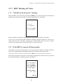
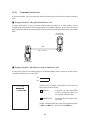
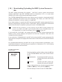
2.3.7 BHT Turning-off Notes
[ 1 ] "Shutdown in progress" message
When the BHT is turned off by pressing the PW key or by the auto power-off feature, it
displays the following message and starts preparation for shutdown.
When the above message is displayed, do not remove the battery cartridge.
If you do so and leave the BHT without a battery cartridge loaded for one hour or
more, then the error message "Contact your administrator. Note the error number.
(2XXX)" may appear when turning the BHT on at the next time.
[ 2 ] If the BHT is turned off abnormally
If the BHT is turned off abnormally* and is left without a battery cartridge loaded or
with a discharged battery cartridge loaded, then unsaved data may be lost.
(*"Normally turned off" refers to "turned off with the PW key or by the auto power-off feature.")
If the above problem has arisen, the following message will appear when you load a
fully-charged battery cartridge and turn the BHT on.
33
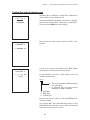
(1)
(2)
Press the 2 key while holding down the SF key. The screen will switch to the
following:
[ 1 ] YES:
Run Scandisk and start the System.
[ 2 ] NO:
Turn the BHT off.
Choose either one with the numerical keys and press the ENT key.
When Scandisk is in progress, the following message is displayed:
34
Chapter 2. Getting Started the BHT and System Mode
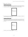
If Scandisk finds an invalid file(s), the following screen will appear. As long as an
invalid file exits, that screen displays every time the BHT System is started up.
(3)
Press the ENT key to start up the BHT System.
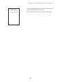
■ Scandisk when the resume function is enabled
If Scandisk runs when the resume function is enabled, the screen given below may
appear. The screen may also appear when the calendar clock built in the BHT stops,
even without running Scandisk.
The BHT displays the screen for three seconds and then automatically runs the execution program from the beginning.
35
[ 3 ] About "$$BRKLST.SYS"
If Scandisk finds an invalid file(s), it will automatically create the "$$BRKLST.SYS" file.
To check the contents of the file, upload the file in System Mode to the host computer.
(Refer to Subsection 2.5.3, "[ 3 ] Uploading.")
Contents of the "$$BRKLST.SYS" file
Records (1) File name
(2) Error factor
+ (Broken since the BHT has not been turned off
normally)
* (Broken due to any other causes)
(3) Broken records
e.g. 01000-01200 (Data in records numbered 1000 to
1200 is lost)
(Example)
SAMPLE1.DAT + 01000-01050
SAMPLE1.DAT + 01200-01250
SAMPLE1.DAT + 01600-01650
SAMPLE2.DAT * 00250-00275
SAMPLE3.DAT * 00100-00150
↑
↑
↑
(1)
(2)
(3)
If more than one sequence of records is broken in
a same file, they will be written into the
subsequent records in the "$$BRKLST.SYS."
[ 4 ] If invalid files are found
Even invalid, files may be uploaded, so upload them to the host computer according to
your needs.
After uploading,
- Delete those invalid files. (Refer to Subsection 2.5.3, "[ 9 ] Deleting Files.")
or
- Download valid files having the same names as invalid files. (Refer to Subsection
2.5.3, "[ 2 ] Downloading.")
36
Chapter 2. Getting Started the BHT and System Mode
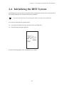
2.4 Initializing the BHT System
Initializing the system will lose program files and data files stored in the user area and
the system settings will revert to the factory defaults.
You may delete font files by selecting the whole user area to be initialized.
You need to initialize the system when:
(1)
you want to delete all of the program files and data files.
(2)
the following message appears.
On the following pages is an initialization procedure.
37
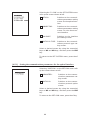
(1)
Selecting the memory area to be initialized
Press the PW key while holding down the SF, M1
and 0 keys together.
The screen shown at left will appear.
To initialize the user area except for the font file
area, press the ENT key. The screen switches to
the SELECT MESSAGE display given in step (2).
To initialize the whole user area including the font
file area, press the 2 key while holding down the
SF key. The "2:WHOLE USER AREA" item will
appear.
(Area selection screen)
1 USER AREA EXCEPT FONTS:
Initializes the user area except for the font
file area.
2 WHOLE USER AREA:
Initializes the whole user area including the
font file area.
If the message "Contact your administrator.
Note the error number. (2XXX)" appears on
the LCD, you need to select "2: WHOLE
USER AREA" to initialize the whole user
area.
Select an area to be initialized by using the numerical keys, then press the ENT key. The screen
switches to the SELECT MESSAGE display given
in step (2).
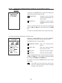
(2)
Selecting the English or Japanese message version
Preceding the execution of initialization, the message version selection screen will appear as shown
at left.
1 Japanese
: Switches the message version to
Japanese.
2 English
: Switches the message version to
English.
Select a desired item by using the numerical keys,
then press the ENT key.
38
Chapter 2. Getting Started the BHT and System Mode
(3)
Confirming the memory area selected for initialization
Selecting the "USER AREA EXCEPT FONTS" in step
(1) above will call up the confirmation screen shown
at left.
1 Yes : Starts initialization.
2 No : Cancels initialization and turns the power
off.
Select a desired item by using the numerical keys,
then press the ENT key.
Pressing the C key will switch the screen back to
the area selection screen.
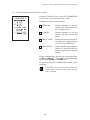
Selecting the "WHOLE USER AREA" in step (1)
above will call up the screen shown at left.
1 Yes:
Starts initialization.
2 No:
Cancels initialization and turns the power
off.
Select a desired item by using the numerical keys,
then press the ENT key.
Pressing the C key will switch the screen back to
the area selection screen.
(4)
During initialization
During initialization, the screen shown at left is
displayed.
Progress in
initialization
39
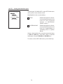
(5)
Completion of initialization
Upon completion of the initialization, the BHT displays the screen shown at left for a second and
turns itself off automatically.
• Do not turn the BHT off until the above initialization completion screen appears.
A too-early powering-off will interrupt initialization, requiring you to initialize
the BHT again.
• If the message "Contact your administrator. Note the error number. (2XXX)"
appears although the initialization has completed, initialize the BHT again.
• If you initialize the BHT after downloading user programs and data, all of those
programs and data stored in the target memory area will be lost. Download them
again if necessary.
• Initialization will reset the LCD contrast level (refer to Subsection 2.3.3), communications conditions and other settings to the factory defaults, so modify them
if necessary. After initialization, be sure to set the calendar clock (refer to
Subsection 2.3.2).
40
Chapter 2. Getting Started the BHT and System Mode
2.5 Operating in System Mode
System Mode is an operating software exclusively designed for the effective use of the
BHT, which includes various functions as shown on the following pages.
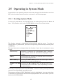
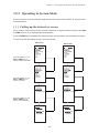
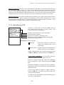
2.5.1 Starting System Mode
To start up System Mode, turn the BHT power on while holding down the SF and 1
keys. This operation calls up the SYSTEM MENU on the LCD as shown below.
The function selected is highlighted (white-on-black) with the cursor. To select a
desired item in System Mode, press the corresponding numerical key and then press
the ENT key.
The keys below are so designed that the function of each key is consistent in every
screen.
Numerical keys
Pressing a numerical key corresponding with a desired
menu number selects the desired item displayed on the
screen.
ENT key
Pressing this key registers the selected item and executes
the corresponding function.
M1 and M2 keys
Pressing the M1 or M2 key moves the cursor up or down,
respectively, to select a desired item.
SF+M1 and SF+M2
keys
Pressing the M1 or M2 key with the SF key held down
moves the cursor to the left or right, respectively, to select
a desired setting.
The C key is inoperative on the SYSTEM MENU. On other screens, pressing the C key
returns to the immediately preceding screen.
The power-on default is "EXEC PROGRAM" which is highlighted. Once any other item
is selected, the selected item will become highlighted with the cursor when you turn
back to the SYSTEM MENU.
41
■ Structure of System Mode
SYSTEM MENU ⇐ Press the PW key while holding down the
SF and 1 keys.
Program Execution
Allows you to select a desired user
program to be executed immediately.
(Refer to Subsection 2.5.3, [ 1 ].)
1 and ENT
keys
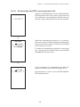
Downloading
Transfers user program files or data
files from the host computer to the
memory integrated in the BHT.
Downloading between the BHTs is also
possible.
(Refer to Subsection 2.5.3, [ 2 ].)
2 and ENT
keys
C key
Uploading
Transfers user program files and data
files stored in the memory of the BHT to
the host computer.
(Refer to Subsection 2.5.3, [ 3 ].)
3 and ENT
keys
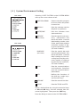
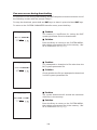
System Environment Settings
Sets a variety of environmental conditions—an execution program, message
version (English or Japanese), calendar
clock, special bar-code scanning
parameters, interface port, communications parameters, functions of the shift
key, magic keys and FUNC keys, resume
function, and TCP/IP and FTP settings.
Shown at left is the BHT-100QF screen.
The BHT-100BF screen displays
"4:BARCODE" instead of "4:QRCODE."
(Refer to Subsection 2.5.3, [ 4 ].)
4 and ENT
keys
42
Chapter 2. Getting Started the BHT and System Mode
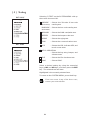
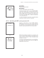
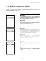
Testing
Used for the code reading test, memory
test, beeper test, aging test, communications test, LCD indication test,
indicator LED test, touch screen test,
key-entry test, vibrator test, file test,
and execution of PING.
Shown at left is the BHT-100QF screen.
The BHT-100BF screen displays
"1:BARCODE" instead of "1:QRCODE."
(Refer to Subsection 2.5.3, [ 5 ].)
5 and ENT
keys
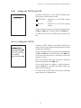
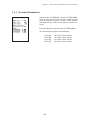
System Information
Shows the system program version,
memory size, system message version,
and JIS font type and version.
(Refer to Subsection 2.5.3, [ 6 ].)
6 and ENT
keys
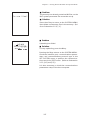
C key
Downloading/Uploading by FTP
Downloads or uploads files by FTP.
(Refer to Subsection 2.5.3, [ 7 ].)
7 and ENT
keys
RF Menu
Sets a network domain name and
security ID for spread spectrum wireless
communication, and gets wireless
module related information.
(Refer to Subsection 2.5.3, [ 8 ].)
8 and ENT
keys
43
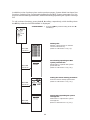
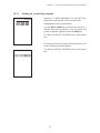
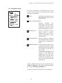
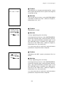
In addition to the functions given on the previous pages, System Mode has these four
functions: Deleting files, Downloading/uploading the BHT system parameter file, Setting the remote wakeup parameters, and Downloading/uploading the system message
file.
To call up these functions, press the 0, 3, 4 or 6 key, respectively, while holding down
the SF key when the SYSTEM MENU is displayed.
SYSTEM MENU ⇐ Press the PW key while holding down the SF
and 1 keys.
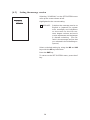
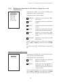
Deleting files
Deletes a program file or data file
stored in the memory.
(Refer to Subsection 2.5.3, [ 9 ].)
0 with SF
held down
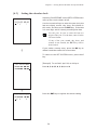
Downloading/uploading the BHT
system parameter file
Downloads or uploads the system
parameter file.
(Refer to Subsection 2.5.3, [ 10 ].)
3 with SF
held down
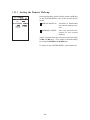
Setting the remote wakeup parameters
Sets the remote wakeup parameters.
(Refer to Subsection 2.5.3, [ 11 ].)
4 with SF
held down
Downloading/uploading the system
message file
Downloads or uploads the system
message file.
(Refer to Subsection 2.5.3, [ 12 ].)
6 with SF
held down
44
Chapter 2. Getting Started the BHT and System Mode
2.5.2 Operating in System Mode
Some functions in System Mode require several screens to be shifted, as shown in the
example below.
[ 1 ] Calling up the desired set screen
First, select a desired item on the current screen by using the numerical key or the M1
and M2 keys so as to highlight the desired item.
Press the ENT key to establish the selected item and proceed to the subsequent screen.
To return to the preceding screen, press the C key.
BHT-100QF
BHT-100BF
Press the 4 key or use
M1 and M2 keys to
select "4:SET SYSTEM."
ENT key
ENT key
C key
C key
Press the 5 key or use
M1 and M2 keys to
select "5:COM."
ENT key
ENT key
C key
C key
Press the 3 key or use
M1 and M2 keys to
select "3:COM PORT."
ENT key
ENT key
C key
45
C key
[ 2 ] Selecting a desired setting
First, select a desired item on the current screen by using the numerical key or the M1
and M2 keys so as to highlight the desired item.
Next, while holding down the SF key, use the M1 and M2 keys to select a desired
setting and then press the ENT key. The screen returns to the previous selection
screen.
Press 2 key or use M1 and M2 keys to
select the desired set item.
Use the SF+M1 and SF+M2 keys to
select the desired setting.
ENT key
46
Chapter 2. Getting Started the BHT and System Mode
2.5.3 Detailed Description of the Functions in System
Mode
[ 1 ] Program Execution
Selecting "1:EXEC PROGRAM" on the SYSTEM
MENU calls up the screen shown at left.
If more than one program has been downloaded
to the user area of the target memory, use the
M1 and M2 keys to move the cursor to a target
program, and then press the ENT key.
To return to the SYSTEM MENU, press the C key.
If more than 22 programs have been downloaded,
you may need to scroll the screen with the M2 key.
⇓
47
⇓
In the example shown at left, 26 programs are
downloaded.
If no program file is downloaded, the message
shown at left will appear.
To return to the SYSTEM MENU, press the C key.
48
Chapter 2. Getting Started the BHT and System Mode
[ 2 ] Downloading
If you download a file having the same name as one already used in the user area of
the target memory in the BHT, the newly downloaded file replaces the old one.
Selecting "2: DOWNLOAD" on the SYSTEM MENU
calls up the screen shown at left.
1 FILE
: Downloads a user program
file or data file to the user
area of the BHT.
2 HT<-->HT COPY : Downloads all of the files,
system parameters, and calendar clock data stored in
the connected BHT.
This function enables copying between the BHTs.
For the preparation to be
made preceding the start of
this function, refer to NOTE
below.
Select a desired item by using the numerical keys
or M1 and M2 keys, and the selected item becomes highlighted. Then press the ENT key.
To return to the SYSTEM MENU, press the C key.
Carrying out "2:HT<-->HT COPY" will not copy the JIS1 and JIS2 font files.
Those font files may be downloaded by "1:FILE."
NOTE
Preparation for Copying between the BHTs
Before downloading to the BHT from another BHT, make the following preparation:
• At each BHT, set the interface port.
(Optical).
The default is an optical interface
Interface setting procedure: Starting on the SYSTEM MENU, select "4:SET
SYSTEM," "5:COM," and "3:COM PORT." On the SET COM PORT screen,
select the optical interface (Optical) or direct-connect interface (Connector)
of "2:SYSTEM MODE."
• When using the direct-connect interface, pull out the connector cover on
each BHT to expose the direct-connect interface port. Connect the BHTs via
those ports with the direct-connect interface cable (having 3-pole mini stereo
plugs). For the details about the cable, refer to Chapter 3, Section 3.2.
• On the uploading BHT, run System Mode and select "3:UPLOAD" and "3:HT<->HT COPY."
49
Download screens
With this screen displayed, the BHT waits for a file
to be downloaded.
If you select "2:HT<-->HT" on the DOWNLOAD
menu, the "HT<-->HT" will appear in the center of
the 2nd line. If you select "1:FILE," nothing will appear on the 2nd line.
The screen at left shows that "1:FILE" has been selected.
⇓
Upon start of optional Ir-Transfer Utility C/Ir-Transfer Utility E/Transfer Utility or equivalent program
(upon receipt of an ENQ code from the host computer), the BHT displays the file name and the
number of received records/the total number of
records on the screen as shown at left.
To abort the downloading operation, press the
C key. The screen will switch back to the
DOWNLOAD menu.
(Refer to the "Ir-Transfer Utility C Guide"/"Ir-Transfer Utility E Guide"/"Transfer Utility Guide.")
⇓
50
Chapter 2. Getting Started the BHT and System Mode
Upon completion of downloading, the number of
received records becomes equal to the total
number of records and the beeper beeps once.
Press the C key to return to the DOWNLOAD menu.
If the host computer downloads another new file (if
the BHT receives an ENQ code) when this screen is
displayed, the BHT starts receiving it.
(Refer to the "Ir-Transfer Utility C Guide"/"Ir-Transfer Utility E Guide"/"Transfer Utility Guide.")
If you have selected "2: HT<-->HT COPY" on the
DOWNLOAD menu, a sequence of the above
screens will be repeated by the number of files to
be downloaded.
If an error occurs during downloading
If some error occurs during downloading, the BHT beeps three times and shows one of
the following screens with the prompt "Retry?":
To retry the download, press the 1 and ENT keys; to abort it, press the 2 and ENT keys.
■ Problem
The memory is insufficient for storing files to be
downloaded.
■ Solution
Press the 2 key to return to the SYSTEM MENU,
then delete unnecessary files in the memory or
decrease the size of the file to be downloaded.
(Refer to Subsection 2.5.3, [ 9 ] and [ 2 ].)
■ Problem
You attempted to download the BHT system parameter file or system message file.
■ Solution
Check the file you attempted to download. Press
the 2 key to return to the SYSTEM MENU and then
download the file in the appropriate menu (SYSTEM PARAMETER transfer menu or SYSTEM MESSAGE transfer menu). (Refer to Subsection 2.5.3,
[ 10 ] and [ 12 ].)
51
■ Problem
The current download will exceed the maximum
of 80 files in the memory.
■ Solution
Press the 2 key to return to the SYSTEM MENU.
Delete unnecessary files in memory or decrease
the number of files to be downloaded if you attempted to download more than one file. (Refer to
Subsection 2.5.3, [ 9 ] and [ 2 ].)
■ Problem
Downloading has failed.
■ Solution
To retry downloading, press the 1 key.
Pressing the 2 key returns to the SYSTEM MENU.
Check the interface port, communications parameters, and communications protocol type in the
SET SYSTEM menu or perform the communications test in the TEST menu. (Refer to Subsection
2.5.3, [4.5] and [5.5].)
It is also necessary to check the communications
parameters setup of the host computer.
■ Problem
You attempted to download an invalid program
file.
■ Solution
Check whether the program file you attempted to
download is available to your BHT model. If it is
not available, download the appropriate program.
52
Chapter 2. Getting Started the BHT and System Mode
[ 3 ] Uploading
Selecting "3: UPLOAD" on the SYSTEM MENU calls
up the screen shown at left.
1 ONE FILE
: Uploads a user program file
or data file stored in the
memory.
2 ALL FILES
: Uploads all user program
files (object programs) and
all data files stored in the
memory.
3 HT<-->HT COPY : Uploads all of the files, system parameters, and calendar clock data stored in the
BHT, to another BHT.
This function enables copying between the BHTs. At
the receiving BHT, select "2:
DOWNLOAD" and "2: HT<->HT COPY" in System Mode.
For the preparation to be
made preceding the start of
this function, refer to NOTE
given on page 49.
Select a desired item by using the numerical keys
or M1 and M2 keys, and the selected item becomes highlighted. Then press the ENT key.
To return to the SYSTEM MENU, press the C key.
Carrying out "3:HT<-->HT COPY" will not copy the JIS1 and JIS2 font files.
Those font files may be uploaded by "1:ONE FILE" or "2:ALL FILES."
If you select "1:ONE FILE" on the UPLOAD menu,
the file selection screen as shown at left will appear, listing all of the program files and data files
stored in the memory. Select a file(s) you want to
upload and press the ENT key.
If you select "2:ALL FILES" or "3:HT<-->HT COPY"
on the UPLOAD menu, the "ALL" or "HT<-->HT" will
appear in the center of the 2nd line, respectively.
53
If you select "1:ONE FILE" or "2:ALL FILES" on the
UPLOAD menu when no files are stored in the
memory, the message shown at left will appear.
Pressing the C key returns to the UPLOAD menu.
Upload screens
If you select "1:ONE FILE" and choose a file to be
uploaded or if you select the "2:ALL FILES" or
"3:HT<-->HT COPY" on the UPLOAD menu, then
the screen shown at left will appear.
If you select "2:ALL FILES" or "3:HT<-->HT COPY,"
the "ALL" or "HT<-->HT" will appear in the center of
the 2nd line, respectively.
Showing this screen, the BHT waits for a file(s) to
be uploaded.
⇓
Upon start of optional Ir-Transfer Utility C/Ir-Transfer Utility E/Transfer Utility or equivalent program
(upon receipt of an ACK code from the host computer), the BHT displays the file name and the
number of sent records/the total number of records
on the screen as shown at left.
To abort the uploading operation, press the C key.
The screen will switch back to the UPLOAD menu.
(Refer to the "Ir-Transfer Utility C Guide"/"Ir-Transfer Utility E Guide"/"Transfer Utility Guide.")
⇓
54
Chapter 2. Getting Started the BHT and System Mode
Upon completion of uploading, the number of sent
records becomes equal to the total number of
records and the beeper beeps once. Press the C
key to return to the UPLOAD menu.
If you have selected "2:ALL FILES" or "3:HT<-->HT
COPY" on the UPLOAD menu, a sequence of the
above screens will be repeated by the number of
files to be uploaded.
If an error occurs during uploading
If some error occurs during uploading, one of the following screens will appear and
the beeper beeps three times.
To retry the uploading operation, press the 1 and ENT keys; to abort it, press the 2 and
ENT keys.
■ Problem
The file you attempted to upload is damaged.
■ Solution
To upload the damaged file as is, press the 1 key.
■ Problem
Uploading has failed.
■ Solution
To retry uploading, press the 1 key.
Pressing the 2 key returns to the SYSTEM MENU.
Check the interface port, communications parameters, and communications protocol type in the
SET SYSTEM menu or perform the communications test in the TEST menu. (Refer to Subsection
2.5.3, [4.5] and [5.5].)
It is also necessary to check the communications
parameters setup of the host computer.
55
[ 4 ] System Environment Setting
BHT-100QF
Selecting "4: SET SYSTEM" on the SYSTEM MENU
calls up the screen shown at left.
1 EXEC PROGRAM
: Sets an execution program
to be run when the power
is turned on.
2 DISPLAY
: Sets the message version
(English or Japanese).
3 DATE/TIME
: Sets the calendar clock
(date and time).
4 QRCODE
: Sets the special code scanning
parameters—the
black-and-white inverted
label reading, marker, view
finder, option data, and the
minimum number of digits to be read for bar codes
(ITF and Codabar).
(BHT-100QF)
BHT-100BF
BARCODE
(BHT-100BF)
: Sets the special bar-code
scanning parameters (the
black-and-white inverted
label reading and the decoding level) and the minimum number of digits to
be read for bar codes (ITF,
STF and Codabar).
5 COM
: Sets the communications
environments (interface
port and communications
parameters).
6 KEY
: Defines the functions of
the shift key, magic keys,
and function keys.
7 RESUME
: Sets the resume function.
8 TCP/IP
: Sets the TCP/IP and FTP.
Select a desired item by using the numerical keys
or M1 and M2 keys, and the selected item becomes highlighted. Then press the ENT key.
Press the C key to return to the SYSTEM MENU.
56
Chapter 2. Getting Started the BHT and System Mode
[4.1]
Setting an execution program
Selecting "1: EXEC PROGRAM" on the SET SYSTEM menu calls up the screen shown at left.
Highlighted is the current setting.
Use the M1 and M2 keys to move the cursor to a
desired execution program to be run when the
power is applied, and then press the ENT key.
To return to the SET SYSTEM menu, press the C
key.
If no program files are stored in the memories, the
screen shown at left will appear.
To return to the SET SYSTEM menu, press the C
key.
57
[4.2]
Setting the message version
Selecting "2: DISPLAY" on the SET SYSTEM menu
calls up the screen shown at left.
Highlighted is the current setting.
1 MESSAGE:
Switches the message version to
English or Japanese for system
error messages and indications
on the screen for the LCD contrast, beeper volume and touch
screen adjustment and the beeper
& vibrator switching. (The default is the message version that
you selected in the initializing sequence.)
Select a desired setting by using the M1 and M2
keys with the SF key held down.
Press the ENT key.
To return to the SET SYSTEM menu, press the C
key.
58
Chapter 2. Getting Started the BHT and System Mode
[4.3]
Setting the calendar clock
Selecting "3:DATE/TIME" on the SET SYSTEM menu
calls up the screen shown at left.
Use the numerical keys to enter the year (only the
last two digits), month, day, hour, and minute in
this order, and then press the ENT key. If the data
is in one digit, add a 0 (zero) preceding the data.
For the year, be sure to enter the last two
digits of the year. For the hour, enter it in the
24-hour format.
If any of the year, month, day, hour, and
minute is not entered, the ENT key will be
deactivated.
⇓
If you make a wrong entry, press the BS key to
delete it and then enter the correct data.
To return to the SET SYSTEM menu, press the C
key.
[Example] To set 2001, April 19, at 4:00 p.m.
Press 0, 1, 0, 4, 1, 9, 1, 6, 0, and 0.
⇓
Press the ENT key to register the above setting.
59
[4.4]
Setting the special scanning parameters
BHT-100QF
Selecting "4: QRCODE" on the SET SYSTEM menu
calls up the screen shown at left.
Highlighted is the current setting.
1 INVERT
: Activates or deactivates the
black-and-white inverted label reading function.
2 DECODE LEVEL : (Not applicable.)
3 MARKER
: Sets the marker ON/OFF
mode.
4 VIEW FINDER
: Turns the view finder on or
off.
5 OPTION DATA : Selects whether or not option data will be added to the
tail of 2D code data read.
6 ITF
: Sets the minimum number of
digits to be read for ITF.
7 CODABAR
: Sets the minimum number of
digits to be read for Codabar.
Select a desired item by using the numerical keys
or M1 and M2 keys, and then select a desired
setting by using the SF+M1 and SF+M2 keys.
To increase the decode level, press the SF+M2
keys; to decrease it, press the SF+M1 keys.
To increase the number of digits to be read for ITF
and Codabar, press the SF+M2 keys; to decrease
it, press the SF+M1 keys.
Press the ENT key.
To return to the SET SYSTEM menu, press the C
key.
Black-and-white inverted label reading function (INVERT)
This function makes it possible to read white bars on a black background.
When this function is activated, the BHT-100QF cannot read codes other than QR
codes.
60
Chapter 2. Getting Started the BHT and System Mode
Marker
You may select the marker ON/OFF mode from the following:
0: Driven by the trigger switch
1: Fixed to ON
2: Fixed to OFF
If you select "1" (Fixed to ON), the markers will keep ON so that power consumption is higher than that in other modes and the battery working time becomes short.
Do not disturb this setting unless necessary.
View Finder
If the View Finder is set to ON, the LCD shows the scanned image of a code lying inside
the scanner's view when you scan the code. Upon completion of scanning, the view
finder display goes off.
Setting the View Finder to ON decreases the scanning speed.
You may set the view finder also by using the OUT statement in BHT-BASIC.
Option Data
If the Option Data is set to ON, the BHT-100QF will add option data (containing 2D code
model and error correction level) to the tail of 2D code data when it reads a 2D code.
This setting takes effect not only in the reading test in System Mode but also in any
other operations. Do not disturb this setting unless necessary.
Option data format
• QR code
Data read
n+1
1
2
3
n-1
n
"Q"
n+2
Model
Option data
n+3 n+4
n+5
Version
n+6
n+7
Error
correction
level
Mask
Example: If a code read is "QR code, Model 2, Version 5, Error correction level M, and
mask number 6," then the option data below will follow.
(Data read)… Q2V05M6
61
• PDF417
Data read
1
2
3
Option data
n-1
n
n+1
n+2
"Y"
Reserved
1
n+3
n+4
Error
correction
level
n+5
n+6
No. of rows
n+7
n+8
No. of digits
Example: If a code read is "PDF417, Error correction level 4, 12 rows and 2 digits," then
the option data below will follow.
(Data read)… Y1041202
• MaxiCode
Data read
1
2
3
n-1
n
n+1
n+2
"X"
Mode
Example: If a code read is "MaxiCode and Mode 4," then the option data below will
follow.
(Data read)… X4
• Data Matrix
Data read
1
2
3
Option data
n-1
n
n+1
n+2
"Z"
Reserved
0
n+3
n+4
n+5
Error correction level
n+6
n+7
n+8
No. of cells (height)
n+9
n+10
n+11
No. of cells (width)
Example: If a code read is "Data Matrix, Error correction level ECC200, 10 cells wide by
10 cells high," then the option data below will follow.
(Data read)... Z0200010010
Minimum number of digits to be read for ITF or Codabar
You may set the minimum number of digits to be read for ITF and Codabar. Setting a
small number of digits increases the frequency of digit-missing reading or misreading
depending upon how to scan bar codes or the quality of bar codes. On the other hand,
setting a large number will diminish the possibility of those errors.
The setting range is from 2 to 20 for ITF and from 3 to 20 for Codabar. The default is 4
for ITF and Codabar.
62
Chapter 2. Getting Started the BHT and System Mode
BHT-100BF
Selecting "4: BARCODE" on the SET SYSTEM menu
calls up the screen shown at left.
Highlighted is the current setting.
1 INVERT
: Activates or deactivates the
black-and-white inverted label reading function.
2 DECODE LEVEL : Sets the decode level.
3 MARKER
: Sets the marker ON/OFF
mode.
4 ITF
: Sets the minimum number of
digits to be read for ITF.
5 STF
: Sets the minimum number of
digits to be read for STF.
6 CODABAR
: Sets the minimum number of
digits to be read for Codabar.
Select a desired item by using the numerical keys
or M1 and M2 keys, and then select a desired
setting by using the SF+M1 and SF+M2 keys.
To increase the decode level, press the SF+M2
keys; to decrease it, press the SF+M1 keys.
To increase the number of digits to be read for ITF,
STF and Codabar, press the SF+M2 keys; to decrease it, press the SF+M1 keys.
Press the ENT key.
To return to the SET SYSTEM menu, press the C
key.
Black-and-white inverted label reading function (INVERT)
This function makes it possible to read white bars on a black background.
Activating this function might increase the frequency of bar-code reading errors.
This function can usually be set to OFF.
DECODE LEVEL
You may set the decode level. Decreasing the level value increases the bar-code
reading efficiency, but the BHT might misread low-quality bar codes (split or stained).
To the contrary, increasing the level value decreases the bar-code reading efficiency,
but it will diminish the possibility of misreading.
The setting range of the level value is from 1 to 9 and the default is 4.
63
Marker
You may select the marker ON/OFF mode from the following:
0: Driven by the trigger switch
2: Fixed to OFF
Minimum number of digits to be read for ITF, STF, or Codabar
You may set the minimum number of digits to be read for ITF, STF, and Codabar.
Setting a small number of digits increases the frequency of digit-missing reading or
misreading depending upon how to scan bar codes or the quality of bar codes. On the
other hand, setting a large number will diminish the possibility of those errors.
The setting range is from 2 to 20 for ITF, from 1 to 20 for STF, and from 3 to 20 for
Codabar. The default is 4 for ITF and Codabar, and 2 for STF.
64
Chapter 2. Getting Started the BHT and System Mode
[4.5]
Setting the communications environments
After the BHT is initialized, the interface port and communications parameters are set
as listed in the default table below. Do not access them unless necessary.
Interface port
Optical (Optical interface port)
Communications protocol
BHT-protocol
Defaults
Communications parameters
for the optical interface port
TRANSMIT SPEED
9600 bps
PROTOCOL
(Protocol options)
SERIAL No.:
ON (Adds serial numbers
to data blocks.)
H. PARITY:
ON (Adds a horizontal
parity.)
LINKUP TIME:
30 seconds
FIELD SPACE:
Ignore
Listed below are the default communications parameters for the direct-connect interface.
Defaults
Communications parameters for
the direct-connect interface port
TRANSMIT SPEED
19200 bps
PARITY BIT
(Vertical parity)
None
DATA BIT
(Character length)
8 bits
STOP BIT
1 bit
PROTOCOL
(Protocol options)
SERIAL No.:
ON (Adds serial numbers
to data blocks.)
H. PARITY:
ON (Adds a horizontal
parity.)
LINKUP TIME:
30 seconds
FIELD SPACE:
Ignore
65
Selecting the "5: COM" on the SET SYSTEM menu
calls up the screen shown at left.
1 OPTICAL:
Switches to the communications parameters setting
screen for the optical interface.
2 CONNECTOR:
Switches to the communications parameters setting
screen for the direct-connect interface.
3 COM PORT:
Switches to the interface
port setting screen.
4 PROTOCOL TYPE:
Switches to the communications protocol type setting screen.
Select a desired screen by using the numerical
keys or M1 and M2 keys, and then press the ENT
key.
To return to the SET SYSTEM menu, press the C
key.
[4.5-1]
Setting the communications parameters for the optical interface
Selecting "1:OPTICAL" on the SET COM menu calls
up the screen shown at left.
1 PARAMETER:
Switches to the communications parameters setting screen.
2 PROTOCOL:
Switches to the communications protocol option
screen.
Select a desired screen by using the numerical
keys or M1 and M2 keys, and then press the ENT
key.
To return to the SET COM menu, press the C key.
66
Chapter 2. Getting Started the BHT and System Mode
(1)
Communications parameters setting screen
Selecting "1:PARAMETER" on the SET OPTICAL
screen calls up the screen shown at left.
Highlighted is the current setting.
Select the desired transmission speed by using
the numerical keys or SF+M1 and SF+M2 keys,
and then press the ENT key.
To return to the SET OPTICAL screen, press the C
key.
(2)
Communications protocol option screen
Selecting "2: PROTOCOL" on the SET OPTICAL
screen calls up the screen shown at left.
Highlighted is the current setting.
1 SERIAL No.:
Selects whether or not the
system will add serial numbers to data blocks.
2 H. PARITY:
Selects whether or not the
system will add a horizontal
parity.
3 LINKUP TIME:
Selects the timeout length (in
seconds) to be applied when
a link is to be established.
4 FIELD SPACE:
Selects whether trailing space
codes in a data field will be
trimmed (ignored) or handled
as data.
Select a desired item by using the numerical keys
or M1 and M2 keys. Then select a desired setting
by using the SF+M1 and SF+M2 keys.
To return to the SET OPTICAL screen, press the C
key.
If the BHT-Ir protocol has been selected, the
serial number and horizontal parity settings
will be ignored.
67
[4.5-2]
Setting the communications parameters for the direct-connect
interface
Selecting "2:CONNECTOR" on the SET COM menu
calls up the screen shown at left.
1 PARAMETER:
Switches to the communications parameters setting screen.
2 PROTOCOL:
Switches to the communications protocol option
screen.
Select a desired screen by using the numerical
keys or M1 and M2 keys, and then press the ENT
key.
To return to the SET COM menu, press the C key.
(1) Communications parameters setting screen
Selecting "1:PARAMETER" on the SET CONNECTOR screen calls up the screen shown at left.
Highlighted is the current setting.
1 TRANSMIT SPEED: Sets the transmission
speed.
2 PARITY BIT:
Sets the vertical parity:
none, odd, or even.
3 DATA BIT:
Sets the character length.
4 STOP BIT:
Sets the stop bit length.
Select a desired item by using the numerical keys
or M1 and M2 keys. Then select a desired setting
by using the SF+M1 and SF+M2 keys.
To return to the SET CONNECTOR screen, press
the C key.
If the BHT-Ir protocol has been selected, the
parity bit, character length, and stop bit length
settings will be ignored.
68
Chapter 2. Getting Started the BHT and System Mode
(2)
Communications protocol option screen
Selecting "2:PROTOCOL" on the SET CONNECTOR
screen calls up the screen shown at left.
Highlighted is the current setting.
1 SERIAL No.:
Selects whether or not the
system will add serial numbers to data blocks.
2 H. PARITY:
Selects whether or not the
system will add a horizontal
parity.
3 LINKUP TIME:
Selects the timeout length (in
seconds) to be applied when
a link is to be established.
4 FIELD SPACE:
Selects whether trailing space
codes in a data field will be
trimmed (ignored) or handled
as data.
Select a desired item by using the numerical keys
or M1 and M2 keys. Then select a desired setting
by using the SF+M1 and SF+M2 keys.
To return to the SET CONNECTOR screen, press
the C key.
If the BHT-Ir protocol has been selected, the
serial number and horizontal parity settings
will be ignored.
69
[4.5-3]
Setting the interface port
Selecting the "3:COM PORT" on the SET COM menu
calls up the screen shown at left.
Highlighted is the current setting.
1 BASIC:
Selects the optical or directconnect interface port to be
used for user programs
written in BHT-BASIC
(OPEN "COM:").
2 SYSTEM MODE:
Selects the optical or directconnect interface port to be
used for downloading or
uploading files in System
Mode.
Select a desired item by using the numerical keys
or M1 and M2 keys, and then select a desired
setting by using the SF+M1 and SF+M2 keys.
To return to the SET COM menu, press the C key.
70
Chapter 2. Getting Started the BHT and System Mode
[4.5-4]
Setting the communications protocol type
Selecting the "4:PROTOCOL TYPE" on the SET COM
menu calls up the screen shown at left.
Highlighted is the current setting.
1 BHT Protocol:
Selects the BHT-protocol for
downloading or uploading
files in System Mode or for
the execution of XFILE statement in BHT-BASIC.
This protocol should be selected for file transmission
with Transfer Utility.
2 BHT-Ir Protocol: Selects the BHT-Ir protocol for
downloading or uploading
files in System Mode or for
the execution of XFILE statement in BHT-BASIC.
This protocol should be selected for file transmission
with Ir-Transfer Utility C/IrTransfer Utility E.
Select a desired item by using the numerical keys
or M1 and M2 keys, and then press the ENT key.
To return to the SET COM menu, press the C key.
71
Selecting the "2:BHT-Ir Protocol" on the PROTOCOL TYPE screen calls up the screen shown at left.
Enter the ID number of the BHT by using the numerical keys, and then press the ENT key. If you
do not need to modify the current setting, press
the ENT key only.
An ID number should be five-digit decimal
character string. The entry range is from
00001 to 65535. If the entry value is less
than five digits, the ENT key will be deactivated.
If you make a wrong entry, press the BS key to
delete it and then enter the correct data.
To return to the SET COM menu, press the C key.
72
Chapter 2. Getting Started the BHT and System Mode
[4.6]
Defining the functions of the shift key, magic keys, and
function keys
Selecting the "6:KEY" on the SET SYSTEM menu
calls up the screen shown at left.
Highlighted is the current setting.
1 SHIFT KEY:
Switches to the shift key definition screen.
2 M1 KEY:
Switches to the M1 key definition
screen.
3 M2 KEY:
Switches to the M2 key definition
screen.
4 M3 KEY:
Switches to the M3 key (left-hand
trigger switch) definition screen.
5 M4 KEY:
Switches to the M4 key (righthand trigger switch) definition
screen.
6 FUNC KEY:
Switches to the function key ON/
OFF screen.
Select a desired screen by using the numerical
keys or M1 and M2 keys, and then press the ENT
key.
To return to the SET SYSTEM menu, press the C
key.
Defining the function of the shift key
Selecting the "1:SHIFT KEY" on the SET KEY menu
calls up the screen shown at left.
Highlighted is the current setting.
1 Nonlock:
Shifts the keypad only when the
SF key is held down.
2 Onetime:
Shifts only one key pressed immediately after the SF key is
pressed. (The following keys will
not be shifted.)
Select a desired setting by using the numerical
keys or M1 and M2 keys, and then press the ENT
key. The screen returns to the SET KEY menu.
73
Defining the function of M1, M2, M3 (left-hand trigger switch), or M4 (right-hand
trigger switch) key
Selecting the "2:M1 KEY," "3:M2 KEY," "4:M3 KEY"
or "5:M4 KEY" on the SET KEY menu calls up the
screen as shown at left. (This example appears
when the "4:M3 KEY" is selected.)
Highlighted is the current setting.
The M1, M2, M3 or M4 key can function as listed
below.
1 None:
The key entry will be ignored.
2 Trigger Switch:
As a trigger switch.
3 Shift Key:
As an SF key.
4 Enter Key:
As an ENT key.
5 Backlight Key:
As a backlight function on/
off key.
Select a desired setting by using the numerical
keys or M1 and M2 keys, and then press the ENT
key. The screen returns to the SET KEY menu.
The M3 and M4 keys are assigned the trigger switch function by default. You can make
them function as the SF key, ENT key, or backlight function on/off key.
If you define the M4 key as the backlight function on/off key, pressing the M4 key
activates or deactivates the backlight function.
In user programs, a string data can also be assigned to these magic keys.
The backlight function on/off key can be assigned only to any one of M1 through
M4 keys. The key defined more recently will act as the backlight function on/off
key and one defined earlier will be ignored.
That is, if you define the M1 and M2 keys as the backlight function on/off key in
this order, the M2 key will work as the backlight function on/off key and the M1
key's entry will be ignored.
74
Chapter 2. Getting Started the BHT and System Mode
Enabling/disabling the function keys
Selecting the "6:FUNC KEY" on the SET KEY menu
calls up the screen shown at left.
Highlighted is the current setting.
1 ALL OFF
Disables all function keys.
2 F1-F4 ON
Enables four function keys F1
through F4.
3 F1-F8 ON
Enables all of the eight function
keys F1 through F8.
Select a desired setting by using the numerical
keys or M1 and M2 keys, and then press the ENT
key. The screen returns to the SET KEY menu.
Display positions of function keys
(When "2:F1-F4 ON" is
selected)
(When "3:F1-F8 ON" is
selected)
• Even if enabled in the above setting, these function keys will not work in System
Mode.
• If the screen scrolls, no function keys will move.
75
[4.7]
Setting the resume function
Selecting "7: RESUME" on the SET SYSTEM menu
calls up the screen shown at left.
Highlighted is the current setting.
1 ON
: Activates the resume function which
resumes the current BHT status
when the BHT power was turned
off, when the BHT is switched on.
2 OFF
: Deactivates the resume function.
Select a desired item by using the numerical keys
or M1 and M2 keys, and then press the ENT key.
To return to the SET SYSTEM menu, press the C
key.
76
Chapter 2. Getting Started the BHT and System Mode
[4.8]
Setting the TCP/IP and FTP
Selecting "8:TCP/IP" on the SET SYSTEM menu
calls up the screen shown at left.
1 SET TCP/IP : Switches to the TCP/IP setting
screen.
2 SET FTP
: Switches to the FTP setting
screen.
Select a desired item by using the numerical keys
or M1 and M2 keys, and then press the ENT key.
To return to the SET SYSTEM menu, press the C
key.
[4.8-1] Setting the TCP/IP
Selecting "1:SET TCP/IP" on the SET TCP/IP menu
calls up the screen shown at left where the current
settings are displayed.
Select a desired item by using the numerical keys
or M1 and M2 keys, and then press the ENT key.
The screen will be placed in the entry mode and
display a cursor.
Enter the desired value by using the numerical
keys and then press the ENT key.
In the entry mode, to delete a single character,
press the BS key. To delete the whole entry you
made, press the C key.
To return to the SET TCP/IP menu, press the C key
when any item is highlighted.
77
[4.8-2] Setting the FTP
Selecting "2:SET FTP" on the SET TCP/IP menu
calls up the screen shown at left.
1 SERVER
: Switches to the FTP server connection environments screen.
2 OPTION
: Switches to the data transfer parameters screen.
Select a desired item by using the numerical keys
or M1 and M2 keys, and then press the ENT key.
To return to the SET TCP/IP menu, press the C key.
(1)
FTP server connection environments screen
Selecting "1:SERVER" on the SET FTP menu calls
up the screen shown at left where the current
settings are displayed.
1 SERVER IP
: Sets the IP address of an FTP
server.
2 USER ID
: Sets a user ID.
3 PASSWORD
: Sets a password.
4 DEFAULT DIR : Specifies an initial directory
through which the FTP server
will search for files for transfer first when the FTP client
gets connected to the server.
Select a desired item by using the numerical keys
or M1 and M2 keys, and then press the ENT key.
The screen will be placed in the entry mode and
display a cursor.
Enter the desired value by using the numerical
keys and period (.) key and then press the ENT key.
Pressing the SF key switches the entry mode between the numeric mode (without a guidance) and
alphabet mode.
In the entry mode, to delete a single character,
press the BS key. To delete the whole entry you
made, press the C key.
To return to the SET FTP menu, press the C key
when any item is highlighted.
78
Chapter 2. Getting Started the BHT and System Mode
(2)
FTP options screen
Selecting "2:OPTION" on the SET FTP menu calls
up the screen shown at left where the current
settings are displayed.
1 CR/LF
: Specifies line delimiters that
should match ones used in
the server OS.
2 CR/LF CODE PROPERTY :
Selects
whether
line
delimiters inside downloaded data records will be
treated as control codes
(record delimiters) or data.
3 FIELD SPACE
: Selects whether trailing
space codes in a downloaded data field will be
trimmed (ignored) or handled as data.
4 UPLOAD MODE : Selects whether uploaded
files will be written over the
existing files or appended to
them.
5 VERBOSE MODE : Selects whether reply codes
& messages (given on page
106) sent by the FTP server
will display on the FTP client or not.
If the VERBOSE MODE is set
to OFF, no such replies will
display but only the messages (given on page 105)
issued by the BHT will appear. If it is set to ON, both
will display.
Select a desired item by using the numerical keys
or M1 and M2 keys. Then select a desired setting
by using the SF+M1 or SF+M2 keys.
To return to the SET FTP menu, press the C key.
79
[ 5 ] Testing
BHT-100QF
Selecting "5:TEST" on the SYSTEM MENU calls up
the screen shown at left.
1 QRCODE
(BHT-100QF)
: Selects the 2D-code & bar-code
reading test.
BARCODE : Selects the bar-code reading test.
(BHT-100BF)
2 MEMORY : Selects the RAM read/write test.
BHT-100BF
3 BEEPER
: Selects the beeper scale test.
4 AGING
: Selects the aging test.
5 COM
: Selects the communications test.
6 LCD
: Selects the LCD, indicator LED, and
touch screen tests.
7 KEY & VIBRATION
: Selects the key entry, beeper, and
vibrator tests.
8 FILE
: Selects the file checksum test.
9 PING
: Selects PING.
Select a desired setting by using the numerical
keys or M1 and M2 keys, and then press the ENT
key. The selected test will start.
Highlighted is the currently selected item.
To return to the SYSTEM MENU, press the C key.
If an error occurs in any of the above tests,
contact your nearest dealer.
80
Chapter 2. Getting Started the BHT and System Mode
[5.1]
2D-code and bar-code reading test
BHT-100QF
Selecting "1: QRCODE" on the TEST menu calls up
the screen shown at left.
Actually read bar codes with the BHT-100QF and
check the read data displayed on the LCD.
Bar-code type
⇓
Sample-1
Number of digits of the code
Code type
Data
Upon completion of 2D-code & bar-code reading,
the BHT-100QF beeps, turns on the indicator LED
in green, and displays the read data together with
the code type and the number of data digits.
If the read data is a 2D code containing the small
number of digits or a bar code, it will display as
shown in Sample-1.
Data read
Sample-2
Code type
If the read data is a 2D code containing the large
number of digits, all data may not display on a
single screen. You may scroll the screen, line by
line or page by page, by using the M1 and M2 keys
or SF+M1 and SF+M2 keys, respectively.
: Shows that this page starts with this digit
of the read data.
: Shows the total number of digits of the
read code.
81
Listed below is a table showing the relationship between the 2D-code/bar-code types
and the identifier letters to be displayed on the LCD.
(Code 39 sample)
Code Type
QR Code
ID Letters
Q
PDF417
Y
MaxiCode
X
Data Matrix
Z
EAN-13, UPC-A
A
EAN-8
B
UPC-E
C
Interleaved 2of5 (ITF)*
I
Codabar (NW-7)*
N
Code 39
M
Code 128
K
EAN-128
W
* The minimum number of digits to be read depends on
the scanning parameter setting. (Refer to [4.4].)
To return to the TEST menu, press the C key.
• The "QR Code" system supports a split QR code feature ("Structured Append")
which can divide data in a QR code into a maximum of 16 blocks and encode
each of them into a split QR code.
When reading split QR codes, the BHT-100QF beeps in a different way from
usual. That is, when the BHT-100QF reads the first split code, it beeps twice and
enters the split code scanning mode. After that, each time it reads the subsequent
split code, it beeps once. If the BHT-100QF reads the last split code, it beeps
three times and completes the sequence of split code scanning.
The scanned data will not be displayed on the LCD until a sequence of split code
scanning is completed.
If you scan any non-split code midway in a sequence of split code scanning, the
BHT-100QF displays the scanned non-split code, cancels the split code scanning
mode, and discards those split codes being scanned. The same occurs also if you
release the trigger switch or the split code scanning interval exceeds approx. 5
seconds.
The scanning order of split codes is arbitrary. The same split code will never be
double-scanned.
• If the OPTION DATA is set to ON on the SET QRCODE screen in the SET
SYSTEM menu (see [4.4] Setting the special scanning parameters), then the
option data will follow QR code data read.
82
Chapter 2. Getting Started the BHT and System Mode
BHT-100BF
Selecting "1: BARCODE" on the TEST menu calls
up the screen shown at left.
Actually read bar codes with the BHT-100BF and
check the read data displayed on the LCD.
⇓
Bar-code type
Number of digits of the bar code
Upon completion of bar-code reading, the BHT100BF beeps, turns on the indicator LED in green,
and displays the read data together with the barcode type and the number of data digits.
To return to the TEST menu, press the C key.
Data
Listed below is a table showing the relationship between the bar-code types and the
identifier letters to be displayed on the LCD.
Bar-code Type
ID Letters
EAN-13, UPC-A
A
EAN-8
B
UPC-E
C
Standard 2of5 (STF)*
H
Interleaved 2of5 (ITF)*
I
Codabar (NW-7)*
N
Code 39
M
Code 93
L
Code 128
K
EAN-128
W
* The minimum number of digits to be read depends on
the scanning parameter setting. (Refer to [4.4].)
83
[5.2]
Memory test
Selecting "2:MEMORY" on the TEST menu calls up
the screen shown at left, and then starts writing
and reading onto/from all areas of the RAM as well
as checking the address.
XXXXX : Tested RAM capacity (in kilobytes)
YYYYY : Total RAM capacity (in kilobytes)
If any error is detected, the BHT beeps three times,
shows the message as shown at left, and terminates the test.
Where,
zzzzzzzz : Address where an error has occurred.
aaaaaaaa : Data to write.
bbbbbbbb : Data read out from the RAM.
To return to the TEST menu, press the C key.
Upon normal completion of the RAM test, the BHT
beeps once, shows the message as shown at left,
and returns to the TEST menu.
84
Chapter 2. Getting Started the BHT and System Mode
[5.3]
Beeper scale test
Selecting "3:BEEPER" on the TEST menu calls up
the screen shown at left and makes the beeper
sound at three octaves listed below.
Upon completion of this test, the BHT automatically returns to the TEST menu.
To stop this test while in progress, turn the power
off and on.
Scale
[5.4]
Frequency (Hz)
do
523
1046
2093
4186
re
587
1174
2349
-
mi
659
1318
2637
-
fa
698
1396
2793
-
sol
783
1567
3135
-
la
880
1760
3520
-
ti
987
1975
3951
-
Aging test
Selecting "4:AGING" on the TEST menu proceeds
to the aging test while showing the current date
and time on the LCD. (This test is intended for
personnel which check the BHT in the factory.)
Once this test is selected, the automatic
powering-off function becomes disabled. Be
sure to turn the power off or press the C key
to return to the TEST menu.
85
[5.5]
Communications test
In System Mode, you may test the optical interface port and direct-connect interface
port.
■ Preparation for the optical interface test
Arrange two BHTs, one as a master station and the other as a slave station (to be
tested) with their IR ports facing each other as illustrated below. In this test, the slave
BHT transmits data to the master BHT and receives the data sent back from the master
BHT.
Slave BHT
(to be tested)
M1
Data
M2
7 ABC
8 DEF
9 GHI
4 JKL
5MNO
6 PQR
1STU
2 VWX
3 YZ
+
BS
0
1STU
,/
C
SF
,/
2 VWX
PW
ENT
3 YZ
+
0
ENT
4 JKL
5MNO
6 PQR
BS
C
SF
PW
0.8 m or less
7 ABC
M1
8 DEF
9 GHI
M2
Master BHT
■ Preparation for the direct-connect interface test
Arrange the 3-pole mini stereo plug as illustrated below and connect it to the directconnect interface port on the BHT.
SD
RD
Selecting the "5:COM" on the TEST menu calls up
the screen shown at left.
1 OPTICAL
: Switches to the MASTER/
SLAVE selection screen for
the optical interface test.
2 CONNECTOR : Tests the direct-connect interface port.
Select a desired item by using the numerical keys
or M1 and M2 keys, then press the ENT key.
86
Chapter 2. Getting Started the BHT and System Mode
Testing the optical interface port
Selecting the "1:OPTICAL" on the TEST COM menu
calls up the screen shown at left.
At the slave BHT to be tested, select the "1:SLAVE"
and at the master BHT, select the "2:MASTER."
Then press the ENT key on each BHT.
During the test, the screen shown at left is displayed.
If any error occurs, the tested slave BHT beeps
three times and shows the screen at left.
In parentheses are error codes which have the
following meanings:
(X X)
1: The received data is different from
the sent data.
2: A timeout has occurred during
standby for data reception.
1: 2400 bps
2: 9600 bps
3: 115200 bps
Press the C key to return to the MASTER/SLAVE
selection menu.
The master BHT will automatically return to the
MASTER/SLAVE selection menu after 10 seconds
from the occurrence of an error.
87
Upon normal completion of the test, the tested
slave BHT beeps once and shows the screen at
left.
Press the C key to return to the TEST COM menu.
The master BHT will automatically return to the
MASTER/SLAVE selection menu.
Testing the direct-connect interface port
Selecting the "2:CONNECTOR" on the TEST COM
menu displays the screen shown at left and then
starts testing the direct-connect interface port.
If any error occurs, the BHT beeps three times and
shows the screen at left.
In parentheses are error codes which have the
following meanings:
(X X)
1: The received data is different from
the sent data.
2: A timeout has occurred during
standby for data reception.
1: 300 bps
2: 115200 bps
88
Chapter 2. Getting Started the BHT and System Mode
Upon normal completion of the test, the BHT beeps
once and shows the screen at left.
Press the C key to return to the TEST COM menu.
89
[5.6]
LCD, indicator LED, and touch screen tests
In System Mode, you may test the LCD, indicator LED, and touch screen.
.
Selecting "6:LCD" on the TEST menu calls up the
screen shown at left on the LCD.
1 LCD:
Tests the LCD and indicator
LED.
2 TOUCH SCREEN1: Tests touch-keys.
3 TOUCH SCREEN2: Tests the graphics pad box by
drawing an image with the
stylus.
Select a desired item by using the numerical keys
or M1 and M2 keys, then press the ENT key.
LCD & indicator LED test
Selecting "1:LCD" on the TEST DISPLAY menu calls
up the test pattern shown at left on the LCD and
turns on the indicator LED in green.
Each time the ENT key is pressed, the screen shifts
to the next test pattern. To return to the previous
screen, press the BS key.
To stop this test while in progress, press the C key.
BS key
⇑ ⇓ ENT key
As shown at left, everything disappear and the
indicator LED lights in red.
BS key
⇑ ⇓ ENT key
90
Chapter 2. Getting Started the BHT and System Mode
The checker pattern shown at left appears and the
indicator LED goes off.
BS key
⇑ ⇓ ENT key
The checker pattern is reversed.
BS key
⇑ ⇓ ENT key
An outline with a width of one dot appears.
BS key
⇑ ⇓ ENT key
91
The fine checker pattern appears.
BS key
⇑ ⇓ ENT key
The fine checker pattern is reversed.
BS key
⇑ ⇓ ENT key
Forty right-angled triangles appear.
BS key
⇑ ⇓ ENT key
92
Chapter 2. Getting Started the BHT and System Mode
BS key
⇑ ⇓ ENT key
BS key
⇑ ⇓ ENT key
Press the ENT key, and the BHT beeps once and
returns to the TEST DISPLAY menu.
BS key
⇑ ⇓ ENT key
93
Touch screen test 1
Selecting "2:TOUCH SCREEN1" on the TEST DISPLAY menu calls up the screen shown at left.
Press individual touch-keys (■) on the LCD. When
each of them is pressed, the beeper will sound and
the key will become highlighted (■). Pressing the
highlighted key again will cancel highlighting (■).
Pressing all five touch-keys (highlighting all) or C
key will return to the TEST DISPLAY menu.
Touch screen test 2
Selecting "3:TOUCH SCREEN2" on the TEST DISPLAY menu calls up the screen shown at left.
You may draw an image with the stylus in the box
(graphics pad box) shown at left.
Press the C key to return to the TEST DISPLAY
menu.
94
Chapter 2. Getting Started the BHT and System Mode
[5.7]
Key entry, beeper, and vibrator test
Selecting "7:KEY & VIBRATION" on the TEST menu
calls up the screen shown at left and makes the
BHT ready for entry from the keypad.
Pressing individual keys displays the identifier letters in the positions pre-assigned to those keys on
the LCD as well as sounding the beeper or running
the vibrator. (As long as the individual key is held
down, the BHT continues beeping or vibrating.)
Pressing the same key again erases the displayed
letter.
The table below shows the relationship between the keys, the identifier letters to be
displayed on the LCD, and the frequencies (Hz) of the beeper.
Key
M3
M1
M2
M4
7
8
9
4
5
6
Letter Beeper (Hz)
F
D
E
G
7
8
9
4
5
6
(Note)
293
329
(Note)
391
440
493
523
587
659
Key
1
2
3
0
.
ENT
BS
C
SF
Letter Beeper (Hz)
1
2
3
0
.
=
A
B
C
698
783
880
987
1046
1174
1318
1396
1567
(Note) Only when the M3 (left-hand trigger switch) or M4 key (right-hand trigger
switch) is pressed, the vibrator works.
After all keys are pressed and displayed on the
LCD, this test automatically ends and the screen
returns to the TEST menu.
To stop this test, turn the power off.
95
[5.8]
File test
Selecting "8:FILE" on the TEST menu calls up the
screen shown at left.
If any of the files stored in the memory is defective, an asterisk (*) or plus sign (+) will be prefixed
to the defective file name(s). For details about the
(*) and (+), refer to Subsection 2.3.7, [ 3 ].
Selecting a file on this screen will show the file
size and the test result.
To select a file, use the M1 and M2 keys to move
the cursor to the desired file. If there are more
than 20 files, the screen will scroll.
Highlighted is the currently selected file.
Press the C key to return to the TEST menu.
The file name, file size, and test result (OK or NG)
appear as shown at left.
Press the C key to return to the file selection screen.
If a defective file is found, delete it or overwrite it with the same name file.
Even defective, the file can be uploaded on the UPLOAD menu. It is, therefore,
recommended that important files be uploaded before deleted.
96
Chapter 2. Getting Started the BHT and System Mode
[5.9]
PING
Selecting "9:PING" on the TEST menu calls up the
screen shown at left.
1 RUN PING
: Runs PING.
2 SET PING
: Switches to the PING parameter
setting screen.
Select a desired item by using the numerical keys
or M1 and M2 keys, and then press the ENT key.
To return to the TEST menu, press the C key.
(1) Running PING
(No.-of-echo requests entry screen)
Selecting "1:RUN PING" on the TEST PING menu
calls up the screen shown at left where the current
settings are displayed.
The COUNT entry box enclosed with brackets is
ready to accept data. If you want to modify the
number of echo requests displayed, enter the desired value by using the numerical keys.
To delete a single character, press the BS key. To
delete the whole entry you made, press the C key.
Press the ENT key to start PING.
⇑
(PING running screen)
Once PING starts running, the message shown at
left will appear.
To stop PING, press the C key.
The PING result may include the following:
OK
: Displays the number of echo replies.
[XXXXX]: Echo reply time in milliseconds
NG
: Displays the number of errors found
during execution of PING.
TIMEOUT : Displays the number of timeouts (for
echo replies) that took place during
execution of PING.
97
PING run-time messages (that will appear in the middle of the LCD)
Message
Displays when:
Waiting
Setting up PING.
Opening TCP/IP
Opening devices.
Routing TCP/IP
Connecting to the TCP/IP communications pathway.
PING start
Starting PING.
Device error
Failed to open a device.
TCP/IP error
Failed to connect to the TCP/IP communications pathway.
PING termination messages (that will appear in the bottom of the LCD)
Message
Displays when:
PING end
PING has ended normally.
PING aborted
PING has aborted.
PING error
An error has occurred during running of PING.
(2) Setting PING parameters
Selecting "2:SET PING" on the TEST PING menu
calls up the screen shown at left where the current
settings are displayed.
1 DESTINATION IP : Specifies the IP address of
a host computer that you
want to ping.
2 DATA SIZE
: Specifies the data size of an
echo request.
3 INTERVAL
: Specifies the echo request
intervals (in units of 100
ms).
4 TIMEOUT
: Specifies the timeout period
(in units of 100 ms) for an
echo request.
5 COUNT
: Specifies the number of
echo requests to be sent.
6 SEND TYPE
: Selects the echo request
send timing TYPE 1 or TYPE
2 (described on page 100).
The entry range for each of "2:DATA SIZE" through
"5:COUNT" items is listed on the next page.
Select a desired item by using the numerical keys
or M1 and M2 keys.
98
Chapter 2. Getting Started the BHT and System Mode
If you select one of "1:DESTINATION IP" through
"5:COUNT" items and press the ENT key, then the
screen will be placed in the entry mode and display a cursor. Enter the desired value by using the
numerical keys and then press the ENT key.
In the entry mode, to delete a single character,
press the BS key. To delete the whole entry you
made, press the C key.
If "6:SEND TYPE" is selected, use the SF+M1 or
SF+M2 keys to choose the desired type.
To return to the TEST PING menu, press the C key
when any item is highlighted.
Entry Range for DATA SIZE, INTERVAL, TIMEOUT, and COUNT
Item
Allowable entry range
Initial value
DATA SIZE
4 to 1472
56
INTERVAL
0 to 65535
10
TIMEOUT
0 to 65535
10
COUNT
0* to 65535
4
* Specification of zero (0) will set the number of echo requests to be sent to "infinite,"
keeping sending echo requests (until PING is aborted).
If you specify a value out of the allowable entry range listed above, the nearest value
within the range will automatically apply.
99
PING Echo Request Send Timing (SEND TYPE)
Two types of echo request send timings are available: TYPE 1 and TYPE 2.
■ TYPE 1
After sending an echo request, PING will wait for the period specified by INTERVAL
and then send an echo request again. For TYPE 1, the relationship between the
INTERVAL and TIMEOUT should be "INTERVAL ≥ TIMEOUT."
Sends an echo request
Receives an echo reply
Timeout period
Interval
Sends an echo request
■ TYPE 2
After sending an echo request, PING will wait for an echo reply to be received or for
timeout to occur. After that, PING will wait for the period specified by INTERVAL and
then send an echo request again. For TYPE 2, no relationship between the INTERVAL
and TIMEOUT is required.
If PING receives an echo reply:
Sends an echo request
Receives an echo reply
Interval
Sends an echo request
If timeout occurs:
Sends an echo request
Timeout period
Timeout occurs
Interval
Sends an echo request
100
Chapter 2. Getting Started the BHT and System Mode
[ 6 ] System Information
Selecting the "6:VERSION" on the SYSTEM MENU
calls up the screen shown at left, displaying the
system program version, memory sizes, system
message version, and JIS font types and their versions.
Press the C key to return to the SYSTEM MENU.
The following font types are displayed:
JIS2
JIS1
JIS2
JIS1
101
(16):
(16):
(12):
(12):
JIS
JIS
JIS
JIS
Level
Level
Level
Level
2
1
2
1
font,
font,
font,
font,
16-dot
16-dot
12-dot
12-dot
[ 7 ] Downloading/Uploading by FTP
Selecting "7:FTP" on the SYSTEM MENU calls up
the screen shown at left.
1 DOWNLOAD : Downloads a file by FTP.
2 UPLOAD
: Uploads a file(s) by FTP.
Select a desired item by using the numerical keys
or M1 and M2 keys, and then press the ENT key.
To return to the SET SYSTEM menu, press the C
key.
[7.1] Downloading by FTP
Selecting "1:DOWNLOAD" on the FTP MENU calls
up the screen shown at left where the current settings are displayed.
IP address of an FTP server you have specified
Current directory reserved
Entry box for a directory and/or file name
Entry box for field information of a data file to be
downloaded
Status message
1 DIR/FILE : Specifies a directory and/or file
name. (For details, refer to the next
page.)
2 FIELDS
: Specifies field information of a data
file. (For details, refer to the next
page.)
Select a desired item by using the numerical keys
or M1 and M2 keys, and then press the ENT key.
The entry box of the selected item becomes ready
to accept entry and a cursor appears.
Enter the desired value by using the numerical
keys and period (.) key and then press the ENT
key.
Pressing the SF key switches the entry mode between the numeric mode (without a guidance) and
alphabet mode.
In the entry mode, to delete a single character,
press the BS key. To delete the whole entry you
made, press the C key.
To return to the FTP MENU, press the C key when
any item is highlighted.
102
Chapter 2. Getting Started the BHT and System Mode
DIR/FILE entry box: The FTP client will interpret a character string entered into this box
as a directory name at first, so it will send a Change Directory request to the FTP
server. If the specified directory exists in the FTP server, the server will change a
directory from the default to that specified one; if not, the FTP client will interpret the
entered character string as a file name and send a Download request to the server.
FIELDS entry box: Only when downloading a data file, you need to enter field information into this box. Before starting downloading, enter field information by using
numerical keys and period (.) key. Pressing the period (.) key will enter a comma (,). For
downloading of program files, nothing is required to enter.
[7.2] Uploading by FTP
Selecting "2:UPLOAD" on the FTP MENU calls up
the screen shown at left if a file(s) exists. The
current settings are displayed.
IP address of an FTP server you have specified
Current directory reserved
Entry box for a directory and/or file name
File name currently selected (Nothing displays at the
initial state of the FTP client.)
Status message
1 DIR/FILE
: Specifies a directory and/or file
name. (For details, refer to the
next page.)
2 SELECT FILE : Selects a file to be uploaded. (For
details, refer to the next page.)
Select a desired item by using the numerical keys
or M1 and M2 keys, and then press the ENT key.
If you select "1:DIR/FILE," its entry box becomes
ready to accept entry and shows a cursor.
Enter the desired value by using the numerical
keys and period (.) key, and then press the ENT
key.
Pressing the SF key switches the entry mode between the numeric mode (without a guidance) and
alphabet mode.
In the entry mode, to delete a single character,
press the BS key. To delete the whole entry you
made, press the C key.
To return to the FTP MENU, press the C key when
any item is highlighted.
103
If you select "2:SELECT FILE," the screen shown at
left will appear.
Choose a file to be uploaded by using the M1 and
M2 keys, then press the ENT key. The screen
returns to the previous one where the selected file
displays in the SELECT FILE entry box.
DIR/FILE entry box: The FTP client will interpret a character string entered into this box
as a directory name at first, so it will send a Change Directory request to the FTP
server. If the specified directory exists in the FTP server, the server will change a
directory from the default to that specified one; if not, the FTP client will interpret the
entered character string as a file name and send an Upload request to the server.
If a file name specified here is different from that specified in the SELECT FILE entry
box, then the FTP client will use the file name specified in this entry box for uploading.
If you enter no file name and press the ENT key, then the FTP client will use the file
name specified in the SELECT FILE entry box for uploading.
SELECT FILE entry box: For uploading, you need to choose a file to be uploaded and
display its name in this entry box. Without a file name in this entry box, uploading will
result in an error.
If the attributes (e.g., PD3, FN3, EX3, and extensions of data files) of the selected file
are different from those specified in the DIR/FILE entry box, then an error will result.
If no file exists when uploading by FTP is selected
If no file exists in the BHT when you select
uploading by FPT, the message shown at left will
appear.
Press the C key to return to the FTP MENU.
104
Chapter 2. Getting Started the BHT and System Mode
Run-time messages in downloading/uploading by FTP
When the BHT is uploading or downloading files by FTP, the following messages may
appear in the bottom of the LCD:
Messages
Displays when:
Aborted.
Uploading or downloading is interrupted.
Connection error
The communications pathway is disconnected.
Device error
Failed to open a device.
Downloading
Downloading starts.
Download failed
Downloading has abnormally ended.
Download finished
Downloading has finished normally.
File broken!
In uploading, the specified file is broken.
File not found!
In downloading, no file is found.
File not selected
No file is selected.
File type mismatch!
In uploading, the attributes of the file selected in the
SELECT FILE entry box are different from those in the
DIR/FILE entry box.
FTP error
During execution of an FTP command, an error has occurred.
FTP opened
Connection is established by FTP.
Illegal text format!
The format of a received text is illegal.
Opening device
Opening a device.
Out of memory!
The memory is insufficient for storing files to be
downloaded.
Out of range!
The specified parameter(s) is out of the allowable range.
Parameter error!
In downloading, the record length and/or field length
specified in the FIELDS entry box exceed 255.
Program file error!
The received program file is illegal.
Routing TCP/IP
Connecting to the TCP/IP communications pathway.
Syntax error!
A syntax error has occurred.
TCP/IP error
Failed to connect to the TCP/IP communications pathway.
TCP socket error
During execution of an FTP command, an error has occurred in the TCP layer.
Too many files!
The current download will exceed the allowable number
of files in the memory.
Uploading
Uploading starts.
Upload failed
Uploading has abnormally ended.
Upload finished
Uploading has finished normally.
105
Reply codes from the FTP server
The messages that FTP servers send during and after FTP operations vary, but servers
all use the same reply codes as listed below.
Reply codes
110
120
125
150
200
202
211
212
213
214
215
220
221
225
226
227
230
250
257
331
332
350
421
425
426
450
451
452
500
501
502
503
504
530
532
550
551
552
553
Description
Restart marker reply.
Service ready in nnn minutes.
Data connection already open; transfer starting.
File status okay; about to open data connection.
Command okay.
Command not implemented, superfluous at this site.
System status, or system help reply.
Directory status.
File status.
Help message.
On how to use the server or the meaning of a particular non-standard command.
This reply is useful only to the human user.
NAME system type.
Where NAME is an official system name from the list in the Assigned Numbers
document.
Service ready for new users.
Service closing control connection.
Logged out if appropriate.
Data connection open; no transfer in progress.
Closing data connection.
Requested file action successful (for example, file transfer or file abort).
Entering Passive Mode (h1, h2, h3, h4, p1, p2).
User logged in, proceed.
Requested file action okay, completed.
"PATHNAME" created.
User name okay, need password.
Need account for login.
Requested file action pending further information.
Service not available, closing control connection.
This may be a reply to any command if the service knows it must shut down.
Can't open data connection.
Connection closed; transfer aborted.
Requested file action not taken.
File unavailable (e.g., file busy).
Requested action aborted: local error in processing.
Requested action not taken.
Insufficient storage space in system.
Syntax error, command unrecognized.
This may include errors such as command line too long.
Syntax error in parameters or arguments.
Command not implemented.
Bad sequence of commands.
Command not implemented for that parameter.
Not logged in.
Need account for storing files.
Requested action not taken.
File unavailable (e.g., file not found, no access).
Requested action aborted: page type unknown.
Requested file action aborted.
Exceeded storage allocation (for current directory or dataset).
Requested action not taken.
File name not allowed.
106
Chapter 2. Getting Started the BHT and System Mode
[ 8 ] RF Menu
Selecting "8:RF" on the SYSTEM MENU calls up
the screen shown at left.
1 SET ID
: Switches to the ID entry screen.
2 VERSION
: Switches to the RF version
screen.
Select a desired item by using the numerical keys
or M1 and M2 keys, and then press the ENT key.
To return to the SYSTEM MENU, press the C key.
[8.1]
ID entry screen
Selecting "1:SET ID" on the RF MENU calls up the
screen shown at left.
The "1:DOMAIN" shows the current setting. The
"2:SECURITY ID" shows 20 asterisks (*) to observe
secrecy.
1 DOMAIN
: Sets a network domain name
(any of 0 to 15).
2 SECURITY ID: Specifies a security ID (max. 20
characters).
Select a desired item by using the numerical keys
or M1 and M2 keys, and then press the ENT key.
For a network domain name, use the SF+M1 or
SF+M2 keys to select the desired value.
To enter a new security ID code, first press the
ENT key to switch to the alphanumeric entry mode.
A cursor will appear at the tail of the 20 asterisks.
Then press the C key to clear all 20 asterisks and
enter the desired code.
For details about the domains and security IDs,
refer to Subsection 3.1.2.
107
Shown at left is an entry sample screen where a
security ID is DENSO WAVE.
After entry, press the ENT key. Instead of the
"DENSO WAVE" entered, 20 asterisks will display.
Pressing the SF key switches the entry mode between the numeric mode (without a guidance) and
alphabet mode.
In the entry mode, to delete a single character,
press the BS key. To delete the whole entry you
made, press the C key.
Pressing the C key when any item is highlighted
will display the confirmation message as shown at
left.
To save the new entry, choose "1:Yes" and press
the ENT key. The "** Now Setting **" will appear
and the screen will return to the RF MENU.
To cancel the new entry, choose "2:No" and press
the ENT key. The newly entered value will be
discarded and the screen will return to the RF
MENU.
When the "** Now Setting **" displays, the
newly entered security ID will be written onto
the EEPROM of the wireless module built in
the BHT.
While this message is displayed, do not turn
the BHT off. Writing halfway onto the
EEPROM will not bring any assured settings.
Be sure to record your security ID. There is
no way to read it out from the EEPROM of
the wireless module.
As long as you do not set a new security ID,
the previous setting will be retained.
When setting a security ID, pressing the ENT
key without entering any character string will
set a default value to the EEPROM of the
wireless module.
108
Chapter 2. Getting Started the BHT and System Mode
[8.2]
RF version screen
Selecting "2:VERSION" on the RF MENU displays
the "** Loading **" while the system is getting
information about the wireless module. After that,
the screen shown at left will appear.
Vx.x
Firmware version of the wirelsss module
MACID
MACID of the wireless module
To return to the RF MENU, press the C key.
If an error occurs for wireless-module parameters or information:
If some error occurs when the system is saving wireless-module parameters or getting
wireless-module information, one of the following screens will appear.
■ Problem
The system has failed to save parameters into the
wireless module.
XXXXXXXXXXXX:
Title of a menu where the
error occurs.
■ Problem
The system has failed to read setting from the
wireless module.
XXXXXXXXXXXX:
109
Title of a menu where the
error occurs.
[ 9 ] Deleting Files
You may delete a program file or data file stored in the memory.
File deletion menu
Pressing the 0 key while holding down the SF key
on the SYSTEM MENU calls up the screen shown
at left.
Use the M1 and M2 keys to move the cursor to the
file to be deleted, then press the ENT key.
Press the C key to return to the SYSTEM MENU.
If no file is resident in the memory, the message
shown at left appears.
Press the C key to return to the SYSTEM MENU.
Deletion confirmation screen
Selecting a file to be deleted and then pressing
the ENT key calls up the confirmation screen shown
at left.
1 Yes :
Deletes the selected file.
2 No :
Cancels deletion and returns to the previous file deletion menu.
Select a desired item by using the numerical keys,
then press the ENT key.
110
Chapter 2. Getting Started the BHT and System Mode
When deletion is in progress, the screen shown at
left is displayed.
⇓
Deletion completion screen
Upon completion of deletion, the screen shown at
left appears.
Press the C key to return to the file deletion menu.
111
[ 10 ] Downloading/Uploading the BHT System Parameter
File
The BHT system parameter file (named "_ _BHT.SYS") stores system environment
settings specified in the SET SYSTEM menu (in Subsection 2.5.3, [ 4 ]) and other
settings such as the LCD contrast and beeper volume.
The SYSTEM PARAMETER transfer menu allows you to upload or download the BHT
system parameter file to/from the host computer. This helps you make the same
settings for the BHTs as those made in a single BHT.
First, make settings in a particular BHT and upload the BHT system parameter file to
the host computer by using this menu ("2:UPLOAD"). Next, let other BHTs download
the file from the host computer by using this menu ("1:DOWNLOAD").
Without the host computer, you may directly copy the BHT system parameter file
between two BHTs (one BHT runs UPLOAD and the other, DOWNLOAD). For
the preparation to be made beforehand, refer to NOTE on page 49.
If you select the "2:UPLOAD," the system will set up the BHT system parameter file
based on the current settings and upload it to the host computer. After that, the
created file will be deleted.
If you select the "1:DOWNLOAD," the BHT will receive the BHT system parameter file
from the host computer and apply the stored values. After that, the received file will be
deleted.
For uploading/downloading, the BHT will use the communications parameters, communications protocol, and interface port specified in Subsection 2.5.3, "[4.5] Setting
the communications environments."
SYSTEM PARAMETER
transfer menu
Pressing the 3 key while holding down the SF key
on the SYSTEM MENU calls up the screen shown
at left.
1 DOWNLOAD:
Downloads the BHT system parameter file to the user area of
the BHT.
2 UPLOAD:
Uploads the BHT system parameter file stored in the BHT.
Select a desired item by using the numerical keys
or M1 and M2 keys, then press the ENT key.
Press the C key to return to the SYSTEM MENU.
112
Chapter 2. Getting Started the BHT and System Mode
[10.1] Downloading the BHT system parameter file
Selecting "1:DOWNLOAD" on the SYSTEM PARAMETER transfer menu calls up the screen shown at
left. With this screen displayed, the BHT waits for
the BHT system parameter file to be downloaded.
⇓
While the downloading operation is in progress,
the screen shown at left is displayed indicating the
file name and the number of received records/the
total number of records.
To abort the downloading operation, press the C
key. The screen will switch back to the SYSTEM
PARAMETER transfer menu.
⇓
Upon completion of downloading, the BHT displays the screen shown at left and beeps once.
Press the C key to return to the SYSTEM PARAMETER transfer menu.
113
If an error occurs during downloading
If some error occurs during downloading, the BHT beeps three times and shows one of
the following screens with the prompt "Retry?":
To retry the download, press the 1 and ENT keys; to abort it, press the 2 and ENT keys.
To return to the SYSTEM PARAMETER transfer menu, press the C key.
■ Problem
The memory is insufficient for storing the BHT
system parameter file to be downloaded.
■ Solution
Press the 2 key to return to the SYSTEM MENU,
then delete unnecessary files in the memory. (Refer to Subsection 2.5.3, [ 9 ] .)
■ Problem
You attempted to download a file other than the
BHT system parameter file.
■ Solution
Check whether the file you attempted to download
is a BHT system parameter file.
■ Problem
The current download will exceed the maximum
of 80 files in the memory.
■ Solution
Press the 2 key to return to the SYSTEM MENU,
then delete unnecessary files in the memory. (Refer to Subsection 2.5.3, [ 9 ].)
114
Chapter 2. Getting Started the BHT and System Mode
■ Problem
Downloading has failed.
■ Solution
To retry downloading, press the 1 key.
Pressing the 2 key returns to the SYSTEM MENU.
Check the interface port, communications parameters, and communications protocol type in the
SET SYSTEM menu or perform the communications test in the TEST menu. (Refer to Subsection
2.5.3, [4.5] and [5.5].)
It is also necessary to check the communications
parameters setup of the host computer.
[10.2] Uploading the BHT system parameter file
Selecting "2:UPLOAD" on the SYSTEM PARAMETER transfer menu calls up the screen shown at
left. With this screen displayed, the BHT waits for
the BHT system parameter file to be uploaded.
⇓
While the uploading operation is in progress, the
screen shown at left is displayed indicating the file
name and the number of sent records/the total
number of records.
To abort the uploading operation, press the C key.
The screen will switch back to the SYSTEM PARAMETER transfer menu.
115
⇓
Upon completion of uploading, the BHT displays
the screen shown at left and beeps once.
Press the C key to return to the SYSTEM PARAMETER transfer menu.
If an error occurs during uploading
If some error occurs during uploading, one of the following screens will appear and
the beeper beeps three times.
To retry the uploading operation, press the 1 and ENT keys; to abort it, press the 2 and
ENT keys.
Press the C key to return to the SYSTEM PARAMETER transfer menu.
■ Problem
The file you attempted to upload is broken.
■ Solution
To upload the broken file as is, press the 1 key.
■ Problem
The memory is insufficient for setting up the BHT
system parameter file to be uploaded.
■ Solution
Press the C key to return to the SYSTEM MENU,
then delete unnecessary files in the memory. (Refer to Subsection 2.5.3, [ 9 ].
116
Chapter 2. Getting Started the BHT and System Mode
■ Problem
The memory has already contained 80 files, so the
BHT system parameter file cannot be set up.
■ Solution
Press the C key to return to the SYSTEM MENU,
then delete unnecessary files in the memory. (Refer to Subsection 2.5.3, [ 9 ].
■ Problem
Uploading has failed.
■ Solution
To retry uploading, press the 1 key.
Pressing the 2 key returns to the SYSTEM MENU.
Check the interface port, communications parameters, and communications protocol type in the
SET SYSTEM menu or perform the communications test in the TEST menu. (Refer to Subsection
2.5.3, [4.5] and [5.5].)
It is also necessary to check the communications
parameters setup of the host computer.
117
[ 11 ] Setting the Remote Wakeup
Pressing the 4 key while holding down the SF key
on the SYSTEM MENU calls up the screen shown
at left.
1 REMOTE WAKE UP:
Activates or deactivates
the remote wakeup function.
2 TRANSMIT SPEED:
Sets the transmission
speed for the remote
wakeup.
Select a desired item by using the numerical keys
or M1 and M2 keys. Then select a desired setting
by using the SF+M1 and SF+M2 keys.
To return to the SYSTEM MENU, press the C key.
118
Chapter 2. Getting Started the BHT and System Mode
[ 12 ] Downloading/Uploading the System Message File
The system message file (named "_ _SYSMSG.FN2") stores system messages, e.g.,
"Shutdown in progress. Do not remove the battery." and "Charge the battery!."
The SYSTEM MESSAGE transfer menu allows you to upload or download the system
message file to/from the host computer.
If you select the "2:UPLOAD," the system will set up the system message file based on
the current settings and upload it to the host computer. After that, the created file will
be deleted.
If you select the "1:DOWNLOAD," the BHT will receive the system message file from
the host computer and apply the stored messages. After that, the received file will be
deleted.
For uploading/downloading, the BHT will use the communications parameters, communications protocol, and interface port specified in Subsection 2.5.3, "[4.5] Setting
the communications environments."
Usually you do not need to use this SYSTEM MASSAGE transfer menu since
system messages have been set at the time of delivery from the factory.
SYSTEM MESSAGE
transfer menu
Pressing the 6 key while holding down the SF key
on the SYSTEM MENU calls up the screen shown
at left.
1 DOWNLOAD:
Downloads the system message file to the user area of
the BHT.
2 UPLOAD:
Uploads the system message
file stored in the BHT.
Select a desired item by using the numerical keys
or M1 and M2 keys, then press the ENT key.
Press the C key to return to the SYSTEM MENU.
119
[12.1] Downloading the system message file
Selecting "1:DOWNLOAD" on the SYSTEM MESSAGE transfer menu calls up the screen shown at
left. With this screen displayed, the BHT waits for
the system message file to be downloaded.
⇓
While the downloading operation is in progress,
the screen shown at left is displayed indicating the
file name and the number of received records/the
total number of records.
To abort the downloading operation, press the C
key. The screen will switch back to the SYSTEM
MESSAGE transfer menu.
⇓
⇓
Upon completion of downloading, the BHT displays the screen shown at left and beeps once.
Press the C key to return to the SYSTEM MESSAGE transfer menu.
When the BHT downloads the system message file, it creates a temporary file named
"_SYSMSG.FN3" in the user area. If the
user area is insufficient for creating the temporary file, therefore, an error will result.
The created temporary file will be automatically deleted after completion of
downloading.
120
Chapter 2. Getting Started the BHT and System Mode
If an error occurs during downloading
If some error occurs during downloading, the BHT beeps three times and shows one of
the following screens with the prompt "Retry?":
To retry the download, press the 1 and ENT keys; to abort it, press the 2 and ENT keys.
To return to the SYSTEM MESSAGE transfer menu, press the C key.
■ Problem
The memory is insufficient for storing the system
message file to be downloaded.
■ Solution
Press the 2 key to return to the SYSTEM MENU,
then delete unnecessary files in the memory. (Refer to Subsection 2.5.3, [ 9 ].)
■ Problem
You attempted to download a file other than the
system message file.
■ Solution
Check whether the file you attempted to download
is a system message file.
■ Problem
The current download will exceed the maximum
of 80 files in the memory.
■ Solution
Press the 2 key to return to the SYSTEM MENU,
then delete unnecessary files in the memory. (Refer to Subsection 2.5.3, [ 9 ].)
121
■ Problem
Downloading has failed.
■ Solution
To retry downloading, press the 1 key.
Pressing the 2 key returns to the SYSTEM MENU.
Check the interface port, communications parameters, and communications protocol type in the
SET SYSTEM menu or perform the communications test in the TEST menu. (Refer to Subsection
2.5.3, [4.5] and [5.5].
[12.2] Uploading the system message file
Selecting "2:UPLOAD" on the SYSTEM MESSAGE
transfer menu calls up the screen shown at left.
With this screen displayed, the BHT waits for the
system message file to be uploaded.
⇓
While the uploading operation is in progress, the
screen shown at left is displayed indicating the file
name and the number of sent records/the total
number of records.
To abort the uploading operation, press the C key.
The screen will switch back to the SYSTEM MESSAGE transfer menu.
122
Chapter 2. Getting Started the BHT and System Mode
Upon completion of uploading, the BHT displays
the screen shown at left and beeps once.
Press the C key to return to the SYSTEM MESSAGE transfer menu.
When the BHT uploads the system message
file, it creates a temporary file named
"_SYSMSG.FN3" in the user area. If the
user area is insufficient for creating the temporary file, therefore, an error will result.
The created temporary file will be automatically deleted after completion of uploading.
If an error occurs during uploading
If some error occurs during uploading, one of the following screens will appear and
the beeper beeps three times.
To retry the uploading operation, press the 1 and ENT keys; to abort it, press the 2 and
ENT keys.
Press the C key to return to the SYSTEM MESSAGE transfer menu.
■ Problem
The file you attempted to upload is broken.
■ Solution
To upload the broken file as is, press the 1 key.
123
■ Problem
The memory is insufficient for setting up the system message file.
■ Solution
Press the C key to return to the SYSTEM MENU,
then delete unnecessary files in the memory. (Refer to Subsection 2.5.3, [ 9 ].
■ Problem
The memory has already contained 80 files, so the
BHT system message file cannot be set up.
■ Solution
Press the C key to return to the SYSTEM MENU,
then delete unnecessary files in the memory. (Refer to Subsection 2.5.3, [ 9 ].
■ Problem
Uploading has failed.
■ Solution
To retry uploading, press the 1 key.
Pressing the 2 key returns to the SYSTEM MENU.
Check the interface port, communications parameters, and communications protocol type in the
SET SYSTEM menu or perform the communications test in the TEST menu. (Refer to Subsection
2.5.3, [4.5] and [5.5].)
It is also necessary to check the communications
parameters setup of the host computer.
124
Chapter 3. Communications Operations of the BHT-100QF/100BF
Chapter 3
Communications Operations of
the BHT-100QF/100BF
This chapter describes the communications operations of the BHT-100QF/100BF—the
spread spectrum communication, RS-232C interface specifications, the basic communications specifications, and the communications protocols—for data transfer with the
host computer or other devices.
3.1
3.2
3.3
3.4
3.5
Spread Spectrum Communication .......................................................................
3.1.1 Notes for Wireless Operations ......................................................................
3.1.2 Domains and Security IDs .............................................................................
Infrared Communication .......................................................................................
RS-232C Interface Specifications ..........................................................................
[ 1 ] Interface Connector and Pin Assignment .............................................
[ 2 ] Interface Cable Connection ....................................................................
Basic Communications Specifications and Parameters .....................................
3.4.1 Basic Communications Specifications ..........................................................
3.4.2 Communications Parameters ........................................................................
Communications Protocols ...................................................................................
3.5.1 BHT-protocol ...................................................................................................
[ 1 ] Overview ..................................................................................................
[ 2 ] Control Characters ..................................................................................
[ 3 ] Basic Format of Transmission Messages ..............................................
[ 4 ] Text Format ..............................................................................................
3.5.2 BHT-Ir Protocol ................................................................................................
[ 1 ] Overview ..................................................................................................
[ 2 ] Control Characters ..................................................................................
[ 3 ] Basic Format of Transmission Messages ..............................................
[ 4 ] Text Format ..............................................................................................
125
126
126
126
128
130
130
131
132
132
134
135
135
135
136
138
139
141
141
142
144
145
3.1 Spread Spectrum Communication
3.1.1 Notes for Wireless Operations
• If there are too many communications errors, first make sure that the BHT points
directly at an access point because the 2.4-GHz band requires a more or less
straight line path. Note also that the low-power radio waves have trouble passing
through human bodies and other obstacles along that path.
• The radio link will not operate properly in the vicinity of microwave ovens, industrial heaters, high-frequency medical equipment, and other sources of radio waves
in the 2.4-GHz band.
• Electromagnetic noise from personal computers, refrigerators, and other home
appliances can also interfere with link operation.
• Environmental factors that can also interfere with link operation include large
metallic objects, metallic dust, or metallic walls in the vicinity of the path and
vibration at either end.
To System Designers:
• Before developing the application, make sure that the intended environment is free
of the interference factors above and thus actually capable of supporting link
operation.
• Assume that there will be communications failures requiring robust retry
capabilities in the software.
• When introducing the BHT link operation into an environment where equipment
using radio waves in the 2.4-GHz band operates or when introducing such
equipment after the introduction of the BHT link operation, be sure to confirm that
the BHT radio link operates properly with all equipment being in operation
beforehand.
• If the environment of the radio communications system is changed after the
introduction (e.g., newly installed household appliances and movement/addition of
shelves or objects), then confirm that the radio link operates properly again before
the actual use.
3.1.2 Domains and Security IDs
Programs written in BHT-BASIC control wireless communication with commands between the BHT terminals and access points which are connected each other by a
wireless LAN.
■ Domains
It is necessary to group a wireless LAN into domains and assign them with unique
domain names. A domain name should be included in the IDs of access points.
You may roam between access points during wireless communication if those access
points are within wireless networks having a same domain name.
For the setting procedure of domain names, refer to Subsection 2.5.3, [ 8 ] RF Menu.
126
Chapter 3. Communications Operations of the BHT-100QF/100BF
■ Security IDs
For assuring higher security, set security IDs to the BHTs. Those IDs should match
those of the access points.
Usually, use a same security ID for a company or a department (or section).
For the setting procedure of security IDs, refer to Subsection 2.5.3, [ 8 ] RF Menu.
127
3.2 Infrared Communication
The BHT has an integrated infrared (IR) communications device which enables wireless transfer of programs and data between the BHT and the host computer and
between the BHTs, instead of the conventional wire transfer.
The IR communications device features the following:
•
Wireless communications
•
Small and lightweight design
•
High transmission speed
•
Freedom from the codes/regulations and licenses which differ from country to
country, unlike radio devices
The BHT may communicate with other IrDA-compliant equipment just by aligning their
IR ports with each other. The effective IR range and IR port angle may differ depending
upon the target equipment, so observe the instructions given in manuals furnished
with such equipment.
If IR transfer fails, bring the BHT closer to the target station or change the IR port
angle, and try again.
128
Chapter 3. Communications Operations of the BHT-100QF/100BF
The BHT's IR communications device is IrDA-compliant. IrDA stands for Infrared Data
Association, which has defined hardware (IrDA Serial Infrared Physical Layer Link) and
communications protocols for IR communications.
The BHT's physical layer complies with the IrDA1.0, with a maximum transfer distance
of 0.8 m and maximum transmission rate of 115.2 kbits per second.
The BHT adopts the exclusive BHT-Ir protocol which allows you to develop user
programs for IR communications in BHT-BASIC, as can be done with conventional wire
communications.
User programs
BHT-BASIC
BHT-Ir protocol
Physical layer
(IrDA1.0)
129
3.3 RS-232C Interface Specifications
[ 1 ] Interface Connector and Pin Assignment
The BHT has a direct-connect interface port which is connectable to the 3-pole mini
stereo plug (ø2.5 mm or 0.1") and supports a subset of the RS-232C interface as shown
below.
Using a direct-connect interface cable having the mini stereo plugs makes it possible
to connect the BHT to a host computer (or another BHT) directly without any routing
through the CU-7000.
SD
RD
SG
3-pole Mini Stereo Plug (ø2.5 mm or 0.1")
The poles of the plug are assigned as listed below.
Signal Name
Function
Signal Input/Output
BHT
External device
SD
Send data
→
RD
Receive data
←
SG
Signal ground
The input/output voltage threshold for the logical valued signal is listed below.
Logical Value
Input Voltage Threshold
Output Voltage Threshold
(RD)
(SD)
0
3V min.
5V min.
1
-3V max.
-5V max.
• The direct-connect interface port is not designed to stand frequent connecting/
disconnecting. Do not plug and unplug basically more than one time a day;
otherwise, the service life of the plug will shorten. To connect the BHT to a host
computer having no IR port (or another BHT) frequently, use the CU-7000.
• Allow the specified signals only to enter the direct-connect interface port. Entry
of other signals will result in a failure or malfunction of the BHT.
130
Chapter 3. Communications Operations of the BHT-100QF/100BF
[ 2 ] Interface Cable Connection
Connect the BHT directly to a host computer, a modem, or a printer with a directconnect interface cable as illustrated below.
BHT
Connector I/F
Host Computer
FG
SD
RD
RS
CS
DR
SG
CD
ER
SD
RD
SG
Cable Connection between BHT and Host Computer
BHT
Connector I/F
Modem
FG
SD
RD
RS
CS
DR
SG
CD
ER
SD
RD
SG
Cable Connection between BHT and Modem
BHT
Connector I/F
Printer
FG
SD
RD
busy(RD)
busy
SG
SG
Cable Connection between BHT and Printer
131
3.4 Basic Communications Specifications and Parameters
3.4.1 Basic Communications Specifications
Listed below are the communications specifications when the BHT exchanges data
with a host computer through the CU-7000 (optical interface) or direct-connect interface cable.
Optical Interface
Direct-connect Interface
Start-stop
Synchronization
Transmission Speed
2400, 9600, 19200, 38400,
57600, or 115200 bps
300, 600, 1200, 2400, 4800, 9600,
19200, 38400, 57600, or 115200 bps
Transmission Code
JIS 8-bit codes
JIS 7- or 8-bit codes
Transmission Bit Order
Vertical Parity
LSB (Least significant bit) first
Even, odd, or none
None
■ Synchronization
For accurate data transaction, it is very important to synchronize the transmission
between the sender and receiver. To do this, it is required to previously define the
bit order and position, the character length, and the beginning and end of the
character to be transmitted.
The start-stop synchronization is an asynchronous system which synchronizes
each character as a unit; that is, it externally adds start and stop bits to the leading
and trailing bit positions of the character to be transmitted, respectively. A clock
starts counting on receiving the start bit and it falls into a non-communication state
on receiving the stop bit. The number of the stop bits is selectable (1 or 2 bits).
■ Transmission Speed
Maximum number of bits to be transmitted per second. Expressed in bps (bits per
second).
■ Optical Interface Communications Range
The optical interface's maximum effective range is 80 cm (31.5 in.) with the IR beam
within a 10˚ angle of divergence.
■ Switching Time between Sending and Receiving on Optical Interface
The optical interface should satisfy the following requirements in switching between sending and receiving:
(1)
Within 10 ms from completion of sending, the optical interface should become
ready to receive.
(2)
After 10 ms or more from completion of receiving, the optical interface should
start sending.
132
Chapter 3. Communications Operations of the BHT-100QF/100BF
■ Transmission Code and Bit Order
All characters should be coded to 7- or 8-bit code for data transmission. The
standard data exchange code of the BHT is JIS 7- or 8-bit code. The transmission
bit order is LSB (Least significant bit) first.
What follows is an example for transmitting character A (41h, 01000001b) coded to
JIS 8-level code with an even parity and a single bit each for start and stop bits.
LSB
1
MSB
0
0
0
0
0
1
0
0
Stop bit
Start bit
Parity bit
■ Vertical Parity
A vertical parity bit is a redundancy bit which is added to every character to be
transmitted in order to check that data has been transmitted accurately. The parity
bit should be set to "1" or "0" depending upon the parity parameter setting, to make
the number of set bits in the character even or odd. The receiver counts the
number of set bits in the transmitted character code to make sure that it has the
selected number (even or odd) of set bits.
The vertical parity bit is positioned immediately following the MSB (Most significant bit) as shown below.
LSB
b0
MSB
b1
b2
b3
b4
b5
b6
(For 7-bit data)
Vertical parity bit
LSB
b0
MSB
b1
b2
b3
b4
b5
b6
b7
(For 8-bit data)
Vertical parity bit
133
3.4.2 Communications Parameters
In System Mode and user programs written in BHT-BASIC, you may set the communications parameters listed below.
Communications Port
Optical interface
Direct-connect interface
Transmission Speed
2400, 9600, 19200, 38400,
57600, or 115200 bps
300, 600, 1200, 2400, 4800, 9600,
19200, 38400, 57600, or 115200 bps
Character Length
8 bits
7 or 8 bits
Vertical Parity
None
Odd, even, or none
Stop Bit Length
1 bit
1 or 2 bits
In System Mode
Refer to Chapter 2, Subsection 2.5.3, "[4.5] Setting the communications environments."
In BHT-BASIC
To set the transmission speed, character length, vertical parity, and stop bit length (To
set the transmission speed only for the optical interface), use the OPEN "COM:"
statement in BHT-BASIC.
OPEN "COM: ... "
Opens the interface port selected in System Mode.
OPEN "COM1: ... "
Opens the optical interface port for data transmission,
irrespective of the setting in System Mode.
OPEN "COM2: ... "
Opens the direct-connect interface port for data transmission, irrespective of the setting in System Mode.
Note that it is impossible to open both the optical interface port and the direct-connect
interface port concurrently.
Through the interface port opened by the OPEN "COM:" statement, the XFILE
statement transmits a designated file.
134
Chapter 3. Communications Operations of the BHT-100QF/100BF
3.5 Communications Protocols
The BHT supports both the BHT-protocol and the BHT-Ir protocol for file transmission.
3.5.1 BHT-protocol
[ 1 ] Overview
The BHT-protocol is the communications procedure used to transmit files between the
BHT and a host (or between the BHTs). It adopts the response method using ACK/NAK
codes.
The BHT-protocol is composed of a defined set of the control character sequences
including the following three phases:
Phase 1:
Establishment of data link
The sending station confirms that the receiving station is ready to
receive data.
Phase 2:
Data transmission
The sending station transmits data to the target receiving station.
Phase 3:
Release of data link
The sending station confirms whether or not all of the transmitted
data has been correctly received by the receiving station. If yes, the
sending station terminates the data transmission and releases the
data link.
For details about the transmission control sequences and horizontal parity checking,
refer to Appendix B, B.1, "BHT-protocol."
135
[ 2 ] Control Characters
The control characters are classified into two groups: transmission control characters
and text control characters.
(1) Transmission control characters
The transmission control characters listed below are used to compose transmission
control sequences in phases 1 through 3.
Symbol
Value
Meaning
Function
EOT
04h
End Of Transmission
Releases a data link (Phase 3).
Requests abort of transmission
(Phase 2).
ENQ
05h
Enquiry
Requests establishment of a data link
(Phase 1).
Prompts the receiver to respond to
the sent text (Phase 2).
ACK
06h
Acknowledge
Acknowledgment response to ENQ
(Phase 1).
Acknowledgment response to text
(Phase 2).
Acknowledgment response to EOT
(Phase 3).
NAK
15h
Negative Acknowledge
Negative acknowledgment response
to ENQ (Phase 1).
Negative acknowledgment response
to text (Phase 2).
■ Transparency
The BHT uses the non-transparent mode which handles the control characters and
codes (e.g., STX, ETX, and SOH) as starting or ending markers and does not allow
them to be transmitted as normal data in the transmission texts.
136
Chapter 3. Communications Operations of the BHT-100QF/100BF
(2) Text control characters
The text control characters are used to format transmission texts. In the BHT-protocol,
they include the following headers and a terminator.
Symbol
Value
Meaning
Function
SOH
01h
Start Of Heading
Indicates the start of heading text (Phase
2).
STX
02h
Start of Text
Indicates the start of data text (Phase 2).
ETX
03h
End of Text
Indicates the end of data text (Phase 2).
You may designate values of headers and a terminator with the protocol functions in
BHT-BASIC. If you designate none of them in a user program, the BHT may apply
those as listed above. Refer to the "BHT-BASIC Programmer's Manual (BHT-100
series)."
137
[ 3 ] Basic Format of Transmission Messages
Basically, the BHT transmits data as units of a file. First, it transmits a heading text
which includes the attribute information of a file (e.g., file name and the number of
data texts) to be transmitted. Following the heading text, it transmits the data text in
the file. A heading text and data text comprise a text.
In actual text transmission, the text is divided into several blocks, then a header and
terminator are added to each block. If the serial number management or error
checking by BCC (Block Check Character) is required, the serial number or BCC is also
added to each block, respectively. This procedure forms a transmission block. A set of
transmission blocks makes up one transmission message.
Shown below is an example of a transmission message formed with the BHT-protocol.
Text
Heading text
S
O
H
Transmission
Message
Data text 1
Data text 2
Heading text
Data text n
E
T
X
B
C
C
Transmission block
S
T
X
Serial
number
(5 bytes)
Data text 1
E
T
X
B
C
C
Transmission block
S
T
X
Serial
number
Data text n
E
T
X
B
C
C
Transmission block
In the above figure, SOH, STX, and ETX are text control characters as described in [ 2 ]
Control Characters, (2). A serial number is expressed by a five-digit decimal number,
starting from 00001 to 32767, and identifies transmitted data texts. For the BCC, refer
to Appendix B, B.1, "BHT-protocol," [ 3 ].
138
Chapter 3. Communications Operations of the BHT-100QF/100BF
[ 4 ] Text Format
Text should be formatted according to the standard of the BHT-protocol before transmission. Shown below are two types of the standard text formats for program files
and data files.
■ Program Text Format
(1) Heading text
Byte position
1
2 3
4
5
6
7
8
9 10 11 12 13 14 15 16 17
Number of data
texts contained
(5 bytes)
Program file name
(12 bytes)
Example of
contents
P R O G 1 .
P D 3
The program file name should
be a maximum of 12 characters
in length and it consists of FILE
NAME and .EXTENSION. The
FILE NAME should be 1 to 8
characters. The EXTENSION
should be .PD3 (.FN3 and .EX3
may be available for future
functional expansion).
0
0 3
If the program file name is
less than 12 characters in
length, the lower blank
bytes will be filled with
space characters.
5 2
The number of data texts
should be 0 to 32767. If it
is less than 5 digits, the
upper blank bytes will be
filled with zeros (0).
(2) Data text
128
or
130
Byte
position
1
2
3 4
128 bytes if extension is .PD3;
130 bytes if it is .FN3 or .EX3.
Program data
0 0 0
Example of
contents
Object file (compiled from a source
program file having one of the
extensions .PD3, .FN3, and .EX3.)
139
0 0 0
If a program data field
is less than the
maximum digits in
length, the lower blank
bytes will be filled with
zeros (0).
■ Data Text Format
(1) Heading text
Byte
position
Number of fields
(2 bytes)
Length of
data field 1 Length of
data field n
(2 bytes)
(2 bytes)
1 2 3 4 5 6 7 8 9 10 11 12 13 14 15 16 17 18 19 20 21
Number of data
texts contained
(5 bytes)
Data file name
(12 bytes)
Example of
contents
M A S T E R
.
D A T
n
0 0 5 9 2
The data file name should be a
maximum of 12 characters in length
and it consists of FILE NAME and
.EXTENSION. The FILE NAME should
be 1 to 8 characters. The EXTENSION
should be other than .PD3, .FN3, and
.EX3, and it may be omitted (together
with a period).
The number of data
texts should be 0 to
32767. If it is less than 5
digits, the upper blank
bytes will be filled with
zeros (0).
1 0
Every data field should be
1 to 254 digits in length. If
it is less than 2 digits, the
upper blank byte will be
filled with zero (0).
If a data field is 100 to 199
digits in length, @0 to I9
will be given; if it is 200 to
254 digits, P0 to U4 will be
given.
@
A
B
20X
21X
...
...
...
...
If the data file name is less
than 12 characters in length,
the lower blank bytes will be
filled with space characters.
0 6
18X
19X
H
I
24X
25X
T
U
10X
11X
12X
P
Q
The number of fields should be 1
to 16. If it is less than 2 digits, the
upper blank byte will be filled with
zero (0).
To transfer a data file containing a data field(s) of 100 digits or more, use the
Windows-based Transfer Utility. The MS-DOS–based Transfer Utility does not
support transmission of data fields exceeding 99 digits.
(2) Data text
Data field 1
Example of
contents
Data field 2
Data field n
T 1 0 0 9 1 S 1 2 3
9 2 0 2 1 4 1 3 2 5
If a data field is less than
the maximum digits in
length, the lower blank
bytes will be filled with
space characters.
The total length of all data fields plus the number of the character count bytes (= the
number of the fields) should be 255 bytes or less.
When you transfer five 50-digit (50-byte) fields, for example, the total length of all
data fields is 250 (50 x 5) bytes and the number of the character count bytes is 5.
Accordingly, the total is 255, so you can transfer the file.
140
Chapter 3. Communications Operations of the BHT-100QF/100BF
3.5.2 BHT-Ir Protocol
[ 1 ] Overview
The BHT-Ir protocol is the communications procedure for the serial infrared link, which
is used to transmit files between the BHT and a host (or between the BHTs). It adopts
the response method using ACK/NAK codes. The BHT-Ir protocol can be used also for
communications through the direct-connect interface.
The BHT-Ir protocol is composed of a defined set of the control character sequences
including the following three phases:
Phase 1:
Establishment of data link
The sending station confirms that the receiving station is ready to
receive data.
Phase 2:
Data transmission
The sending station transmits data to the target receiving station.
Phase 3:
Release of data link
The sending station confirms whether or not all of the transmitted
data has been correctly received by the receiving station. If yes, the
sending station terminates the data transmission and releases the
data link.
For details about the transmission control sequences and CRC, refer to Appendix B,
B.2, "BHT-Ir protocol."
141
[ 2 ] Control Characters
The control characters are classified into two groups: transmission control characters
and text control characters.
(1)
Transmission control characters
The transmission control characters listed below are used to compose transmission
control sequences in phases 1 through 3.
Symbol
Value
Meaning
Function
DLE EOT
1004h
End Of Transmission
Releases a data link (Phase 3).
Requests abort of transmission
(Phase 2).
DLE ENQ 1005h
Enquiry
Requests establishment of a data link
(Phase 1).
Prompts the receiver to respond to
the sent text (Phase 2).
DLE ACK
1006h
Acknowledge
Acknowledgment response to DLE
ENQ (Phase 1).
Acknowledgment response to text
(Phase 2).
Acknowledgment response to DLE
EOT (Phase 3).
DLE NAK 1015h
Negative Acknowledge
Negative acknowledgment response
to DLE ENQ (Phase 1).
Negative acknowledgment response
to text (Phase 2).
WACK
103Bh
Wait for Acknowledge
Requests suspension of data reception during erasure of the flash
memory.
■ Transparency
The BHT uses the transparent mode which allows the control characters and codes
(e.g., STX, ETX, SOH, and DLE) to be transmitted as normal data in the transmission texts.
To transmit a DLE as normal data, type DLE DLE per DLE.
142
Chapter 3. Communications Operations of the BHT-100QF/100BF
(2)
Text control characters
The text control characters are used to format transmission texts.
protocol, they include the following headers and a terminator.
Symbol
Value
In the BHT-Ir
Meaning
Function
DLE SOH 1001h
Start Of Heading
Indicates the start of heading text (Phase
2).
DLE STX
1002h
Start of Text
Indicates the start of data text (Phase 2).
DLE ETX
1003h
End of Text
Indicates the end of data text (Phase 2).
In the BHT-Ir protocol, you cannot change the values of the headers and terminator
with the protocol functions in BHT-BASIC.
143
[ 3 ] Basic Format of Transmission Messages
Basically, the BHT transmits data as units of a file. First, it transmits a heading text
which includes the attribute information of a file (e.g., file name and the number of
data texts) to be transmitted. Following the heading text, it transmits the data text in
the file. A heading text and data text comprise a text.
In actual text transmission, the text is divided into several blocks, then a header,
terminator, serial number, receiver station's ID, and CRC-16 (Cyclic Redundancy Check)
are added to each block. This procedure forms a transmission block. A set of
transmission blocks makes up one transmission message.
Shown below is an example of a transmission message formed with the BHT-Ir
protocol.
Text
Heading
text
S
D
L • O
H
E
Data text 1
Data text 2
I
Heading text
D
Data text n
E
D
L • T
X
E
C
R
C
Transmission
block
E
D
L • T
X
E
C
R
C
Transmission
block
E
D
L • T
X
E
C
R
C
Transmission
block
(2 bytes)
Transmission
Message
S
D
L • T
X
E
S
D
L • T
X
E
I
Serial
number
D
(5 bytes)
I
Serial
number
Data text 1
Data text n
D
In the above figure, DLE SOH, DLE STX and DLE ETX are text control characters as
described in [ 2 ] Control Characters, (2). An ID denotes the ID number of the receiver
station, expressed by two bytes. A serial number is expressed by a five-digit decimal
number, starting from 00001 to 32767, and identifies data texts. For the CRC-16, refer
to Appendix B, B.2, "BHT-Ir protocol, " [ 3 ].
You can use the control characters for expressing IDs, serial numbers, or text data.
144
Chapter 3. Communications Operations of the BHT-100QF/100BF
[ 4 ] Text Format
Text should be formatted according to the standard of the BHT-Ir protocol before
transmission. Shown below are two types of the standard text formats for program
files and data files.
■ Program Text Format
(1) Heading text
Byte position
1
2 3
4
5
6
7
8
9 10 11 12 13 14 15 16 17
Number of data
texts contained
(5 bytes)
Program file name
(12 bytes)
Example of
contents
P R O G 1 .
P D 3
The program file name should
be a maximum of 12 characters
in length and it consists of FILE
NAME and .EXTENSION. The
FILE NAME should be 1 to 8
characters. The EXTENSION
should be .PD3 (.EX3 and .FN3
may be available for future
functional expansion).
0
0 3
If the program file name is
less than 12 characters in
length, the lower blank
bytes will be filled with
space characters.
5 2
The number of data texts
should be 0 to 32767. If it
is less than 5 digits, the
upper blank bytes will be
filled with zeros (0).
(2) Data text
128
or
130
Byte
position
1
2
3 4
128 bytes if extension is .PD3;
130 bytes if it is .EX3 or .FN3.
Program data
0 0 0
Example of
contents
Object file (compiled from a source
program file having one of the
extensions .PD3, .EX3, and .FN3.)
145
0 0 0
If a program data field
is less than the
maximum digits in
length, the lower blank
bytes will be filled with
zeros (0).
■ Data Text Format
(1) Heading text
Number of fields
(2 bytes)
Length of
data field 1
(3 bytes)
Byte
position
1
2
3
4
5
6
7
8
9 10 11 12 13 14 15 16 17 18 19 20 21 22
Number of data
texts contained
(5 bytes)
Data file name
(12 bytes)
Example of
contents
M A
S
T
E
R
.
Length of
data field n
(3 bytes)
D
A
T
0
0
5
9
2
n
The number of data
texts should be 0 to
32767. If it is less than 5
digits, the upper blank
bytes will be filled with
zeros (0).
The data file name should be a
maximum of 12 characters in length
and it consists of FILE NAME and
.EXTENSION. The FILE NAME should
be 1 to 8 characters. The EXTENSION
should be other than .PD3, .EX3, and
.FN3, and it may be omitted (together
with a period).
0
0
6
2
5
4
Every data field
should be 1 to 254
digits in length. If it is
less than 3 digits, the
upper blank bytes will
be filled with zeros (0).
The number of fields should be 1
to 16. If it is less than 2 digits, the
upper blank byte will be filled with
zero (0).
If the data file name is less
than 12 characters in length,
the lower blank bytes will be
filled with space characters.
(2) Data text
Data field 1
Example of
contents
Data field 2
Data field n
T 1 0 0 9 1 S 1 2 3
Every data field should be
1 to 254 digits in length.
9 2 0 2 1 4 1 3 2 5
If a data field is less than
the maximum digits in
length, the lower blank
bytes will be filled with
space characters.
The total length of all data fields plus the number of the character count bytes (= the
number of the fields) should be 255 bytes or less.
When you transfer five 50-digit (50-byte) fields, for example, the total length of all
data fields is 250 (50 x 5) bytes and the number of the character count bytes is 5.
Accordingly, the total is 255, so you can transfer the file.
146
Chapter 4. Error Messages
This chapter lists the error messages which will appear on the LCD if some error
occurs in the BHT-100QF/100BF.
4.1
System Errors ........................................................................................................ 148
4.2
Errors in System Mode ......................................................................................... 153
Chapter 4
Error Messages
147
4.1 System Errors
If some error occurs when the power is turned on or during program execution, one of
the following error messages will appear on the LCD.
System Program error
■ Problem
A System Program error has occurred.
If this error occurs, the BHT beeps five times
(for 0.1 second per beep) and then turns itself
off.
■ Solution
Contact your nearest dealer.
Low battery indication—Level 1
■ Problem
When the power is turned on or off or during execution of program (System Mode or application),
the battery output level has dropped below a
specified lower level limit.
If low battery is detected, the BHT displays
this message for approx. 2 seconds and beeps
three times (for 0.1 second per beep). After
that, it will resume previous regular operation.
■ Solution
The battery recharge or replacement time will
come soon.
Replace or recharge the battery cartridge. (For the
charging procedure, refer to Chapter 5, Section
5.5.)
148
Chapter 4. Error Messages
Low battery indication—Level 2
■ Problem
When the power is turned on or off or during execution of program (System Mode or application),
the battery output level has lowered.
If lower battery is detected, the BHT beeps
five times (for 0.1 second per beep) and then
turns itself off. Depending upon the battery
level, the beeper may not sound five times.
■ Solution
Replace or recharge the battery cartridge. (For the
charging procedure, refer to Chapter 5, Section
5.5.)
Calendar clock stopped
■ Problem
The calendar clock integrated in the BHT has
stopped because:
- The battery cartridge had been removed for a
long time or
- The battery cartridge had not been recharged for
a long time.
The indication of 00/01/01 00:00 will vary
depending upon the calendar clock state.
■ Solution
Set the calender clock (refer to Chapter 2, Subsection 2.3.2).
149
Abnormally turned off last
■ Problem
After turned off abnormally*, the BHT had been
left with no battery cartridge loaded or with a discharged battery cartridge loaded, so unsaved data
was lost.
(*"Normally turned off" refers to turned-off with
the PW key or by the auto power-off feature.)
■ Solution
Refer to Subsection 2.3.7 "BHT Turning-off Notes."
System Program malfunction
■ Problem
During execution of System Program, the System
Program has attempted to write onto the write-protected area of the memory.
(xxxxxxxx: Error address)
If this error occurs, the BHT beeps five times
(for 0.1 second per beep).
■ Solution
Unload and reload the battery cartridge, then turn
on the power.
■ Problem
During execution of System Program, the System
Program has received an invalid command code.
(xxxxxxxx: Error address)
If this error occurs, the BHT beeps five times
(for 0.1 second per beep).
■ Solution
Unload and reload the battery cartridge, then turn
on the power.
150
Chapter 4. Error Messages
Execution program not selected
■ Problem
No user program has been selected as an execution program to be run when the power is turned
on.
If this error occurs, the BHT beeps five times
(for 0.1 second per beep) and then turns itself
off.
■ Solution
Run System Mode and select an execution program in the SET SYSTEM menu. (For the selecting
procedure, refer to Chapter 2, Subsection 2.5.3,
[4.1].)
Resume data lost
■ Problem
No resume data has been retained since the BHT
was not normally turned off and then left with no
battery cartridge loaded or with a discharged battery cartridge loaded even if the resume function
had been set to ON.
The BHT displays this error message for 3
seconds and automatically runs the execution
program from the point of start-up.
Error in System Mode settings
■ Problem
Your settings made in System Mode contain an error.
• If this error occurs, the System Mode
settings revert to the factory defaults.
• The BHT displays this error message for
three seconds and then displays the "No
execution program selected…" message.
■ Solution
Make your settings in System Mode again.
151
System down error
■ Problem
An error has occurred during execution of System
Program.
If this error occurs, the BHT beeps five times
(for 0.1 second per beep).
■ Solution
Unload and reload the battery cartridge, then turn
on the power.
If this error occurs frequently, make a note of the
message and codes on the LCD and contact your
nearest dealer.
System administrator to be called
■ Problem
Any of the following errors has occurred:
(1) Hardware error
Calendar clock error:
Flash memory error:
(1010)
(1020)
(2) Memory storage error
(2XXX)
(3) Execution program error
(3010)
(4) RF system error
(4110)
(XXXX: Error code)
If any of the above errors occurs, the BHT
beeps five times (for 0.1 second per beep)
and then turns itself off.
■ Solution
Turn on the power again.
If error (1) or (4) above occurs frequently, contact
your nearest dealer.
If error (2) occurs frequently, initialize the BHT
System (the whole user area including the font file
area).
If error (3) occurs frequently, delete the execution
program file that causes this error or download
the original execution program file to overwrite
the current one.
152
Chapter 4. Error Messages
4.2 Errors in System Mode
If some error occurs during operation in System Mode, one of the following error
messages will appear on the LCD.
When selecting a program file or data file
■ Problem
You attempted to execute a user program in the
EXECUTE PROGRAM menu, but no user program
files had been stored in the memory.
■ Solution
Press the C key to return to the SYSTEM MENU
screen, then download user programs. (Refer to
Chapter 2, Subsection 2.5.3, [ 2 ].)
■ Problem
In the SET SYSTEM menu, you attempted to select
a user program file as an execution program to be
run when the power is applied, but no user program files had been stored in the memory.
■ Solution
Press the C key to return to the SYSTEM MENU
screen, then download user programs. (Refer to
Chapter 2, Subsection 2.5.3, [ 2 ].)
■ Problem
You attempted to select "ONE FILE" or "ALL FILES"
for uploading in the UPLOAD menu, but no data
files had been stored in the memory.
■ Solution
Press the C key to return to the SYSTEM MENU
screen.
153
■ Problem
You have deleted all of the files stored in the
memory in the DELETE FILE menu.
■ Solution
Press the C key to return to the SYSTEM MENU
screen.
During downloading of a program file,
data file, BHT system parameter file, or
system message file
■ Problem
The memory is insufficient for storing files to be
downloaded.
■ Solution
Press the 2 key to return to the SYSTEM MENU,
then delete unnecessary files in the memory or
decrease the size of the file to be downloaded.
(Refer to Chapter 2, Subsection 2.5.3, [ 9 ], [ 2 ],
[ 10 ], and [ 12 ].)
■ Problem
In the DOWNLOAD menu, you attempted to
download the BHT system parameter file or system message file. In the SYSTEM PARAMETER
transfer menu, you attempted to download a file
other than the BHT system parameter file. Or in
the SYSTEM MESSAGE transfer menu, you attempted to download a file other than the system
message file.
■ Solution
Check the file you attempted to download and
then download the file in the appropriate menu
(DOWNLOAD menu, SYSTEM PARAMETER transfer menu, or SYSTEM MESSAGE transfer menu).
154
Chapter 4. Error Messages
■ Problem
The current download will exceed the maximum
of 80 files in the memory.
■ Solution
Press the 2 key to return to the SYSTEM MENU,
then delete unnecessary files in the memory (or
decrease the number of files to be downloaded if
you attempted to download more than one file in
the DOWNLOAD menu.)
(Refer to Chapter 2, Subsection 2.5.3, [ 9 ], [ 2 ],
[ 10 ], and [ 12 ].)
■ Problem
Downloading has failed.
■ Solution
To retry downloading, press the 1 key.
Pressing the 2 key returns to the SYSTEM MENU.
Check the interface port, communications parameters, and communications protocol type in the
SET SYSTEM menu or perform the communications test in the TEST menu. (Refer to Chapter 2,
Subsection 2.5.3, [4.5] and [5.5].)
It is also necessary to check the communications
parameters setup of the host computer.
■ Problem
Downloading the BHT system parameter file has
failed.
■ Solution
To retry downloading, press the 1 key.
Pressing the 2 key returns to the SYSTEM MENU.
Check the interface port, communications parameters, and communications protocol type in the
SET SYSTEM menu or perform the communications test in the TEST menu. (Refer to Chapter 2,
Subsection 2.5.3, [4.5] and [5.5].)
It is also necessary to check the communications
parameters setup of the host computer.
155
■ Problem
You attempted to download an invalid program
file.
■ Solution
Check whether the program file you attempted to
download is available to your BHT model. If it is
not available, download the appropriate program.
During uploading of a program file, data
file, BHT system parameter file, or system message file
■ Problem
The file you attempted to upload is damaged.
■ Solution
To upload the damaged file as is, press the 1 key.
■ Problem
The memory is insufficient for setting up the BHT
system parameter file or system message file to
be uploaded.
■ Solution
Press the C key to return to the SYSTEM MENU
and delete unnecessary files. (Refer to Chapter 2,
Subsection 2.5.3, [ 9 ].)
156
Chapter 4. Error Messages
■ Problem
The memory has already contained 80 files, so the
BHT system parameter file or system message file
cannot be set up.
■ Solution
Press the C key to return to the SYSTEM MENU
and delete unnecessary files. (Refer to Chapter 2,
Subsection 2.5.3, [ 9 ].)
■ Problem
Uploading has failed.
■ Solution
To retry uploading, press the 1 key.
Pressing the 2 key returns to the SYSTEM MENU.
Check the interface port, communications parameters, and communications protocol type in the
SET SYSTEM menu or perform the communications test in the TEST menu. (Refer to Chapter 2,
Subsection 2.5.3, [4.5] and [5.5].)
It is also necessary to check the communications
parameters setup of the host computer.
■ Problem
Uploading the BHT system parameter file has
failed.
■ Solution
To retry uploading, press the 1 key.
Pressing the 2 key returns to the SYSTEM MENU.
Check the interface port, communications parameters, and communications protocol type in the
SET SYSTEM menu or perform the communications test in the TEST menu. (Refer to Chapter 2,
Subsection 2.5.3, [4.5] and [5.5].)
It is also necessary to check the communications
parameters setup of the host computer.
157
158
Chapter 5. Handling the CU-7000 (Option)
This chapter describes the handling procedure of the CU-7000, the interfacing with the
host computer, and the charging of the rechargeable battery cartridge.
5.1
Functions of the CU-7000 ...................................................................................... 160
5.2
Components and Functions .................................................................................. 160
5.3
Applying Power to the CU-7000 ........................................................................... 161
5.4
Communicating with the Host Computer ............................................................ 162
5.4.1
Setting the Transmission Speed of the CU-7000 ......................................... 162
5.4.2
Interface Cable Connection ............................................................................ 162
5.4.3
Interfacing with the Host Computer .............................................................. 163
5.5
Charging the Rechargeable Battery Cartridge (using the CU-7001) .................. 164
5.6
RS-232C Interface Specifications .......................................................................... 166
[ 1 ] Interface Connector and Pin Assignment ................................................. 166
[ 2 ] Interface Cable Connection ........................................................................ 167
Chapter 5
Handling the CU-7000 (Option)
159
5.1 Functions of the CU-7000
The optical communications unit CU-7000 is available in two models: CU-7001 and CU7002. The CU-7001 has both of functions (1) and (2) given below, the CU-7002 has only
function (1).
(1)
Data exchange function
The CU-7001/CU-7002 exchanges data and programs between the BHT and the
host computer. It interfaces with the BHT via the optical interface and with the
host computer via the RS-232C interface.
(2)
Battery cartridge charging function
The CU-7001 charges the rechargeable battery cartridge loaded in the BHT.
5.2 Components and Functions
LED indicators
DATA (Communications LED, green)
Lights when the BHT is communicating
with the host computer.
POWER (Power LED, green)
Lights when the power is
applied to the CU-7000.
Optical interface port
Used to exchange data
optically with the BHT.
BHT charge terminals
(Not provided on CU-7002)
Do not stain these terminals;
failure to protect the terminals
may result in decreased
charging efficiency.)
CU-7000
RS-232C interface port
Used to exchange data with the host computer.
Power inlet connector
Plug the AC adapter into this connector.
160
Chapter 5. Handling the CU-7000 (Option)
5.3 Applying Power to the CU-7000
Apply power to the CU-7000 by connecting it to the wall socket via the dedicated AC
adapter.
Connect the outlet plug of the AC adapter to the power inlet connector of the CU-7000,
then plug the other end of the AC adapter into the wall socket.
AC adapter
Power inlet connector
WARNING
• If smoke, abnormal odors or noises come from the CU,
immediately unplug the AC adapter from the wall socket
and contact your nearest dealer.
Failure to do so could cause fire or electrical shock.
• If foreign material or water gets into the CU, immediately
unplug the AC adapter from the wall socket and contact
your nearest dealer.
Failure to do so could cause fire or electrical shock.
• If you drop the CU so as to damage its housing, immediately unplug the AC adapter from the wall socket and contact your nearest dealer.
Failure to do so could cause fire or electrical shock.
• Use the dedicated AC adapter only. Failure to do so could
result in a fire.
• Never use the CU on the line voltage other than the specified level. Doing so could cause the CU to break or burn.
• If the power cord of the AC adapter is damaged (e.g.,
exposed or broken lead wires), stop using it and contact
your nearest dealer.
Failure to do so could result in a fire or electrical shock.
CAUTION
• If you are not using the CU for a long time, be sure to
unplug the AC adapter from the wall socket for safety.
Failure to do so could result in a fire.
• When caring for the CU, unplug the AC adapter from the
wall socket for safety.
Failure to do so could result in an electrical shock.
• Never cover or wrap up the CU or AC adapter in a cloth or
blanket.
Doing so could cause the unit to heat up inside, deforming
its housing, resulting in a fire.
Always use the CU and AC adapter in a well-ventilated
area.
• Keep the power cord away from any heating equipment.
Failure to do so could melt the sheathing, resulting in a fire
or electrical shock.
161
5.4 Communicating with the Host
Computer
5.4.1 Setting the Transmission Speed of the CU-7000
Set the transmission speed of the CU-7000 to the same value as that of the BHT and the
host computer, by using the DIP switch provided on the bottom of the CU-7000.
(1)
Turn the CU-7000 upside down.
(2)
Remove the protection sheet of the DIP switch from the CU-7000.
(3)
Set the selectors of the DIP switch as shown below.
For 115,200 bps
ON
OFF
1 2 3
OFF
For 38,400 bps
1 2 3
ON
OFF
OFF
DIP switch (when
the protection
sheet is removed)
OFF
ON
OFF
1 2 3
OFF
For 19,200 bps
ON
OFF
1 2 3
OFF
For 9,600 bps
ON
Bottom View
(4)
1 2 3
For 57,600 bps
OFF
1 2 3
OFF
Reinstall the protection sheet.
Do not set the DIP switch to any configurations other than one of the five shown
above.
5.4.2 Interface Cable Connection
(1)
Unplug the AC adapter of the CU-7000 from the wall socket.
(2)
Make sure that the host computer is turned off.
(3)
Connect the 25-pin plug (Dsub-25P) of the interface cable to the RS-232C interface
port of the CU-7000.
RS-232C interface
cable
(4)
Connect the other end of the interface cable to the RS-232C port of the host
computer.
162
Chapter 5. Handling the CU-7000 (Option)
5.4.3 Interfacing with the Host Computer
This section describes how to start communication with the host computer in System
Mode. The same may apply when you use a user program.
(1)
Turn the host computer on.
(2)
Plug the AC adapter of the CU-7000 into the wall socket.
(3)
Make sure that the BHT is turned off, then set it on the CU-7000.
(4)
Turn the BHT power on and run System Mode. Set the communications environments (communications protocol, interface port, communications parameters,
and protocol options).
Regarding the communications protocol: When using Ir-Transfer Utility C/IrTransfer Utility E on the host computer, select the BHT-Ir protocol; when using
Transfer Utility, select the BHT-protocol.
Regarding the interface port: Select the optical interface port.
(5)
On the host computer, initiate a communications program (e.g., Ir-Transfer Utility
C/Ir-Transfer Utility E/Transfer Utility, or equivalent).
(6)
To transfer data stored in the BHT to the host computer, select "3: UPLOAD" on
the SYSTEM MENU in System Mode. To transfer data from the host computer to
the BHT, select "2: DOWNLOAD." (For details, refer to Chapter 2, Section 2.5.)
The BHT and the host computer will start communications with each other via the
CU-7000. The DATA LED will come on upon start of communications. After
completion of communications, the LED will go off.
(7)
Unplug the AC adapter of the CU-7000 from the wall socket.
163
5.5 Charging the Rechargeable Battery Cartridge (using the CU-7001)
You may charge a rechargeable battery cartridge loaded in the BHT.
Service Life of Rechargeable Battery Cartridge:
Lithium-ion batteries used in the rechargeable battery cartridge will gradually
deteriorate during the repeated cycles of charging and discharging due to its
properties, even under normal use. When the battery service period becomes
shortened due to its deterioration even if it has been charged for the specified hours,
replace the battery cartridge with a new one. Generally, it is necessary to replace
the battery cartridge after it has undergone approx. 300 cycles of charging and
discharging operation.
(1)
Plug the AC adapter of the CU-7001 into the wall socket.
The POWER LED on the CU-7001 lights in green.
(2)
Place the BHT loaded with a battery cartridge onto the CU-7001.
The BHT turns on the indicator LED in red and starts charging. The charging time
is approx. 4 hours.
Upon completion of charging, the indicator LED turns green.
BHT
CU-7001
(3)
Take the BHT off the CU-7001.
The charging time is approx. 4 hours if the "Charge the battery!" message is
displayed on the BHT. The battery cartridge not discharged so much will be fully
recharged in shorter time.
164
Chapter 5. Handling the CU-7000 (Option)
■ Charging Operation and LED Indication
Operator's Action
CU-7001 Status
On standby
Indicator LED on
the BHT
OFF
⇓
Place the BHT
on the CU-7001.
Normal charging
⇓
⇓
After approx. 4 hours
Charging completed
⇓
⇓
Remove the BHT.
On standby
165
ON
(in red)
ON
(in green)
OFF
5.6 RS-232C Interface Specifications
[ 1 ] Interface Connector and Pin Assignment
The CU-7000 has an RS-232C interface port (Dsub-25S).
13
1
25
14
RS-232C interface port (Dsub-25S) on the CU-7000
Pin No.
Signal
1
2
3
4
5
6
7
8
20
FG
SD
RD
RS
CS
DR
SG
CD
ER
Functions
Signal Input/Output
CU-7000 External device
Frame ground
Send data
Receive data
Request to send
Ready to send
Data set ready
Signal ground
Carrier detect
Data terminal equipment ready
—
→
←
—
—
—
—
—
—
The input/output voltage threshold for the logical valued signal is listed below.
Logical Value
Input Voltage Threshold
Output Voltage Threshold
0
3V min.
5V min.
1
-3V max.
-5V max.
166
Chapter 5. Handling the CU-7000 (Option)
[ 2 ] Interface Cable Connection
As illustrated below, connect the CU-7000 (on which the BHT is put) to a host computer
with a cross-mode cable. To connect it to a modem, use a straight-mode cable.
CU-7000
(DTE)
Host Computer
(DTE)
1
FG
SD
RD
RS
CS
DR
SG
CD
ER
2
3
4
5
6
7
8
20
Cable Connection between CU-7000 and Host Computer
Modem
(DCE)
CU-7000
(DTE)
1
FG
SD
RD
RS
CS
DR
SG
CD
ER
2
3
4
5
6
7
8
20
Cable Connection between CU-7000 and Modem
DTE and DCE
In the RS-232C interface specifications, the DTEs (Data Terminal Equipment) shall be
generally connected with each other by a cross-mode cable; the DTE and DCE (Data
Circuit-terminating Equipment) shall be connected with each other by a straight-mode
cable.
The DTE is one piece of equipment connected at both ends of a communications line
as a sender or receiver of data (such as CU-7000 on which the BHT is put and a host
computer).
The DCE is one piece of equipment connected to the intermediate point between the
DTE and the communications line. It terminates communications lines and exchanges
information between those lines without any change in contents (such as modem).
167
168
Appendices
Appendix A. Specifications .............................................................................................. 170
A.1
A.2
BHT-100QF ...................................................................................................... 170
[1]
Product Specifications ............................................................................ 170
[2]
Readable Codes ....................................................................................... 172
[3]
Scanning Performance ........................................................................... 174
[4]
Interface Specifications .......................................................................... 176
BHT-100BF ....................................................................................................... 177
[1]
Product Specifications ............................................................................ 177
[2]
Bar Code Specifications .......................................................................... 179
[3]
Interface Specifications .......................................................................... 181
A.3 CU-7000 ............................................................................................................... 182
[1]
Product Specifications ............................................................................ 182
[2]
Charging Requirements (CU-7001) ........................................................ 182
[3]
Interface Specifications .......................................................................... 183
Appendix B. Communications Protocol Details .............................................................. 184
B.1
B.2
BHT-protocol ................................................................................................... 184
[1]
Transmission Control Sequences .......................................................... 184
[2]
Aborting Data Transmission ................................................................... 192
[3]
BCC for Horizontal Parity Checking ....................................................... 193
BHT-Ir protocol ................................................................................................ 194
[1]
Transmission Control Sequences .......................................................... 194
[2]
Aborting Data Transmission ................................................................... 203
[3]
CRC ........................................................................................................... 204
[4]
ID .............................................................................................................. 204
Appendix C. A Typical Basic Operation ........................................................................... 205
Appendix D. Quality Assurance Standards ..................................................................... 206
D.1
Applicable Standards ..................................................................................... 206
D.2
Interface Cables .............................................................................................. 207
Appendices
169
Appendix A.
Specifications
A.1
BHT-100QF
[ 1 ] Product Specifications
Power Source
Main power
Rechargeable lithium-ion battery cartridge
(3.6 VDC)
Dimensions
(W) x (L) x (H)
67 x 198 x 29 mm
(2.6 x 7.8 x 1.1 inches)
Weight
Approx. 280 g (Approx. 9.9 oz.) including
battery cartridge
Operating Ambient Temperature
-5˚C to 50˚C (23˚F to 122˚F)
Operating Humidity
20% to 80% (with no dew condensation)
Ambient Illuminance
20 to 10000 x.
(Depth of field: 90 mm, QR code: Ver. 5 (37 x
37 cells), Error correction level: M, Cell pitch:
0.5 mm, PCS value: 0.9 min., Reflection
intensity: 85% min. for white)
500 to 3000 x.
(Under the conditions except the above)
Controller
Keypad
CPU:
32-bit RISC
RAM:
1MB
Flash memory:
8MB
Trigger switches (M3, M4) :
2
Magic keys (M1, M2)
:
Numerical keys and others :
2
16
170
Appendices
Display
Type:
Touch screen, dot-matrix, FSTN
liquid crystal display (LCD) with
backlight
Formation:
Character display
200 dots wide by 304 dots high
Status display
200 dots wide by 16 dots high
Screen mode
Font size
Single-byte
ANK* mode
Standard-size
(12-dot)
ANK
Regular-size
Double-width
Double-height
Quadruple-size
12 x 12
24 x 12
12 x 24
24 x 24
16 x 25
8 x 25
16 x 12
8 x 12
Two-byte
Kanji mode
Standard-size
(16-dot)
Full-width
Regular-size
Double-width
Double-height
Quadruple-size
16 x 16
32 x 16
16 x 32
32 x 32
12 x 19
6 x 19
12 x 9
6x9
Half-width
Regular-size
Double-width
Double-height
Quadruple-size
8 x 16
16 x 16
8 x 32
16 x 32
25 x 19
12 x 19
25 x 9
12 x 9
Full-width
Regular-size
Double-width
Double-height
Quadruple-size
12 x 12
24 x 12
12 x 24
24 x 24
16 x 25
8 x 25
16 x 12
8 x 12
Half-width
Regular-size
Double-width
Double-height
Quadruple-size
6 x 12
12 x 12
6 x 24
12 x 24
33
16
33
16
Small-size
(12-dot)
Dots (W x H)
Chars x Lines
x
x
x
x
25
25
12
12
*ANK: Alphanumerics and Katakana
Calendar Clock
Year, month, day, hour, minute, and second
• Year
Reading Confirmation
Two digits (with auto-correction on
February 29 for year 1901 to 2099)
Indicator LED (Red & green), beeper, and
vibrator
171
[ 2 ] Readable Codes
The values given below are based on the scanning reference position shown in the
next item [ 3 ]. (Skew angle: 360˚)
(1) QR Codes (Model 1 and Model 2) and MicroQR
Code size
Cell pitch
21 x 21 cells to 85 x 85 cells
0.25 mm (9.8 mils)
21 x 21 cells to 61 x 61 cells
(105 x 105 cells)*1
0.33 mm (13.0 mils)
11 x 11 cells to 17 x 17 cells*2
0.25 mm (9.8 mils)
*1 Applies to Model 2.
*2 Applies to MicroQR.
(2) PDF417
Number of columns and number of rows
Module size
1 to 5 columns, 3 to 30 rows*3
0.17 mm (6.7 mils)
*3
Excluding start/stop codes and left and right indicators
(3) MaxiCode
Module size
Module pitch
30 (29) x 33 modules
0.88 mm (34.6 mils)
(4) Data Matrix
Code size
Cell pitch
Max. 80 x 80 cells
0.25 mm
Max. 52 x 52 cells
0.33 mm
172
Appendices
(4) Bar Codes
Bar code type
Universal product codes
EAN-13
EAN-8
UPC-A
UPC-E
Bar dimensions
Readable range
0.26 to 0.33 mm
(10.24 to 12.99 mils)
0.26 to 0.46 mm
(10.24 to 18.11 mils)
0.26 to 0.33 mm
(10.24 to 12.99 mils)
0.26 to 0.56 mm
(10.24 to 22.05 mils)
0.8 to 1.0 magnifications
0.8 to 1.4 magnifications
0.8 to 1.0 magnification
0.8 to 1.7 magnifications
Interleaved 2of5 (ITF)
2 to 34 digits*
Codabar (NW-7)
3 to 23 digits
Code 39
0.15 mm min.
(5.91 mils)
Code 128 (EAN-128)
1 to 17 digits
1 to 21 digits
* Only even-numbered digits
All of the above values are under the following conditions:
- Ambient illuminance: 500 to 3000 x.
- Light source: Xenon lamp
(5) Multi-line Code Scanning
The BHT-100QF supports multi-line code scanning that can scan up to 3 lines of codes
out of universal product codes, Interleaved 2of5 (ITF), Codabar (NW-7), Code 39, and
Code 128 (EAN-128) at a time in the specified order.
The multi-line code scanning may be specified in user programs only. For details, refer
to the "BHT-BASIC Programmer's Manual (BHT-100 series)."
(6) Optical Properties Required
White cells (white bars): Reflection intensity
45% min.
Black cells (black bars):
25% max.
0.45 min.
Reflection intensity
PCS value
173
[ 3 ] Scanning Performance
■ Scanning reference position
As illustrated at left, align the
reading window with the center
of the label (code) to be
scanned.
BHT-100QF
90 mm
(3.5")
Label
■ Scanning distance and area
Scanning distance
0
20
40
60
80
100 120 140 160
180 200
0.25 mm (9.8 mils)
0.33 mm (13.0 mils)
0.50 mm (19.7 mils)
119 x 89
(4.7 x 3.5)
Scanning area:
Width x height
Cell pitch of QR codes supported
within this range
0.15 mm (5.9 mils)
0.25 mm (9.8 mils)
0.33 mm (13.0 mils)
QR codes
103 x 77
(4.1 x 3.0)
87 x 65
(3.4 x 2.6)
67 x 50
(2.6 x 2.0)
60 x 44
(2.4 x 1.7)
Reading
window
30 x 22
(1.2 x 0.9)
Scanning reference
position (90 mm or 3.54")
Module size of bar codes
supported within this range
Cell pitch
Scanning distance
30 to 110 mm (1.2 to 4.3 inches)*1
30 to 140 mm (1.2 to 5.5 inches)*1
30 to 200 mm (1.2 to 7.9 inches)*2
0.25 mm (9.8 mils)
0.33 mm (13.0 mils)
0.50 mm (19.7 mils)
PCS value: 0.9 min., Reflection intensity: 85% min. for white
*1 Under these conditions:
QR code Model 2
*2 Under these conditions:
QR code Model 2
174
Ver. 5 (37 x 37 cells)
Error correction level: M
Black and white label
Ver. 3 (29 x 29 cells)
Error correction level: M
Black and white label
Appendices
PDF417
Module size
Scanning distance
40 to 100 mm (1.6 to 3.9 inches)*3
40 to 170 mm (1.6 to 6.7 inches)*3
40 to 200 mm (1.6 to 7.9 inches)*3
0.17 mm (6.7 mils)
0.25 mm (9.8 mils)
0.33 mm (13.0 mils)
PCS value: 0.9 min., Reflection intensity: 85% min. for white
*3 Under these conditions: 1-column, 11-row, Row height: 3 modules,
Error correction level: 1
MaxiCode
Cell pitch
Scanning distance
0.88 mm (34.6 mils)
45 to 230 mm (1.8 to 9.1 inches)
PCS value: 0.9 min., Reflection intensity: 85% min. for white
Data Matrix
Cell pitch
Scanning distance
30 to 110 mm (1.2 to 4.3 inches)*4
30 to 140 mm (1.2 to 5.5 inches)*4
30 to 200 mm (1.2 to 7.9 inches)*4
0.25 mm (9.8 mils)
0.33 mm (13.0 mils)
0.55 mm (21.7 mils)
PCS value: 0.9 min., Reflection intensity: 85% min. for white
*4 Under these conditions: 36 x 36 cells
Error correction level: ECC200
Black and white label
Bar codes
Module size
Scanning distance
40 to 90 mm (1.6 to 3.5 inches)*5
40 to 170 mm (1.6 to 6.7 inches)*6
40 to 200 mm (1.6 to 7.9 inches)*7
0.15 mm (5.9 mils)
0.25 mm (9.8 mils)
0.33 mm (13.0 mils)
PCS value: 0.9 min., Reflection intensity: 85% min. for white
*5 Under these conditions:
Codabar
*6 Under these conditions:
Codarbar
*7 Under these conditions:
EAN-8
10-digit
Narrow bar, Narrow space: 0.15 mm (5.9 mils)
10-digit
Narrow bar, Narrow space: 0.25 mm (9.8 mils)
Module size: 0.33 mm (13.0 mils)
The BHT-100QF may fail to read codes due to specular reflection depending upon the
position of the light source, scanning angle of the reading window, and other conditions.
175
[ 4 ] Interface Specifications
Optical Interface
Synchronization:
Start-stop
Input signals:
RD
Output signals:
SD
Transmission speed:
115200 bps max.
Direct-connect Interface
Synchronization:
Start-stop
Transmission speed:
115200 bps max.
Signal level:
Conforms to the RS-232C interface
Pin assignment:
As shown below.
SD
SG
RD
Signal Input/Output
External
BHT
device
Pin No.
Signal
Functions
1
SG
Signal ground
—
2
SD
Send data
→
3
RD
Receive data
←
Wireless Interface
Wireless system:
Spread spectrum frequency hopping
Bandwidth:
2400 to 2483.5 MHz
Transmission speed:
1.6 Mbps or 0.8 Mbps
Number of channels:
15
176
Appendices
A.2
BHT-100BF
[ 1 ] Product Specifications
Power Source
Main power
Rechargeable lithium-ion battery cartridge
(3.6 VDC)
Dimensions
(W) x (L) x (H)
67 x 198 x 29 mm
(2.6 x 7.8 x 1.1 inches)
Weight
Approx. 280 g (Approx. 9.9 oz.) including
battery cartridge
Operating Ambient Temperature
-5˚C to 50˚C (23˚F to 122˚F)
Operating Humidity
20% to 80% (with no dew condensation)
Ambient Illuminance
500 to 3000 x.
(Depth of field: 30 mm, PCS value: 0.9 min.,
Reflection intensity: 85% min. for white and
5% max. for black, Narrow bar width: 0.125
mm min.)
20 to 10000 x.
(Depth of field: 250 mm, ITF: 1.0 magnification, PCS value: 0.9 min., Reflection intensity:
85% min. for white and 5% max. for black)
Controller
Keypad
CPU:
32-bit RISC
RAM:
512KB
Flash memory:
4MB
Trigger switches (M3, M4) :
Magic keys (M1, M2)
:
Numerical keys and others :
177
2
2
16
Display
Type:
Touch screen, dot-matrix, FSTN
liquid crystal display (LCD) with
backlight
Formation:
Character display
200 dots wide by 304 dots high
Status display
200 dots wide by 16 dots high
Screen mode
Font size
Single-byte
ANK* mode
Standard-size
(12-dot)
ANK
Regular-size
Double-width
Double-height
Quadruple-size
12 x 12
24 x 12
12 x 24
24 x 24
16 x 25
8 x 25
16 x 12
8 x 12
Two-byte
Kanji mode
Standard-size
(16-dot)
Full-width
Regular-size
Double-width
Double-height
Quadruple-size
16
32
16
32
16
16
32
32
12 x 19
6 x 19
12 x 9
6x9
Half-width
Regular-size
Double-width
Double-height
Quadruple-size
8 x 16
16 x 16
8 x 32
16 x 32
25 x 19
12 x 19
25 x 9
12 x 9
Full-width
Regular-size
Double-width
Double-height
Quadruple-size
12
24
12
24
16 x 25
8 x 25
16 x 12
8 x 12
Half-width
Regular-size
Double-width
Double-height
Quadruple-size
6 x 12
12 x 12
6 x 24
12 x 24
Small-size
(12-dot)
Letter type
Dots (W x H)
x
x
x
x
x
x
x
x
12
12
24
24
Chars x Lines
33
16
33
16
x
x
x
x
25
25
12
12
*ANK: Alphanumerics and Katakana
Calendar Clock
Year, month, day, hour, minute, and second
• Year
Reading Confirmation
Two digits (with auto-correction on
February 29 for year 1901 to 2099)
Indicator LED (Red & green), beeper, and
vibrator
178
Appendices
[ 2 ] Bar Code Specifications
(1) Available Bar Code Types
Bar code type
Bar dimensions
Readable magnification
Universal product codes
EAN-13
EAN-8
UPC-A
UPC-E
EAN-13 with supplemental codes
0.26 mm min.
(10.24 mils min.)
0.8 min.
EAN-8 with supplemental codes
UPC-A with supplemental codes
UPC-E with supplemental codes
2-digit add-on
5-digit add-on
Interleaved 2of5 (ITF)
Standard 2of5 (STF)
Codabar (NW-7)
0.125 mm min. (4.92 mils min.)
PCS value ≥ 0.75
Reflection intensity difference between white
and black bars ≥ 0.4
0.15 mm min. (5.91 mils min.)
(PCS value ≥ 0.45)
Code 39
Code 93
Code 128 (EAN-128)
0.15 mm min. (5.91 mils min.)
(PCS value ≥ 0.45)
(2) Optical Properties Required
White bars: Reflection intensity
45% min.
Black bars:
25% max.
0.45 min.
Reflection intensity
PCS value
179
(3) Bar Code Label Size
Recommended width: 10 mm min. (0.39 inch min.)
Length:
Depth of field
(Distance from bar codes to
the reading window)
400 mm (15.75 inches)
Length of labels
(including margins)
380 mm max. (14.96 inches max.)
(Minimum narrow bar width:
1.0 mm min.)*4
Length
Width
(4) Thickness of Bars and Depth of Field
Minimum narrow bar width
0.125 mm
0.15 mm
0.33 mm
1.0 mm
1.2 mm
(4.92 mils)
(5.91 mils)
(12.99 mils)
(39.37 mils)
(47.24 mils)
Depth of field
0 to 30 mm
0 to 70 mm
0 to 150 mm
140 to 350 mm
160 to 400 mm
*1 Under the following conditions:
- Ambient illuminance: 500 x. (Fluorescent
lamp)
- Code 39, 19-digit
Narrow bar : Wide bar = 1 : 2.2
- Reflection intensity of white bars: 85% min.
Reflection intensity of black bars: 5% max.
(0 to 1.18 inches)*1
(0 to 2.76 inches)*2
(0 to 5.91 inches)*3
(5.51 to 13.78 inches)*4
(6.30 to 15.75 inches)*5
*4 Under the following conditions:
- Ambient illuminance: 500 x. (Fluorescent
lamp)
- ITF conforming to the UPC Shipping Container Code
- Reflection intensity of white bars: 85% min.
Reflection intensity of black bars: 5% max.
- 1.0 magnification
*2 Under the following conditions:
- Ambient illuminance: 500 x. (Fluorescent
lamp)
- Code 39, 6-digit
Narrow bar : Wide bar = 1 : 2.2
- Reflection intensity of white bars: 85% min.
Reflection intensity of black bars: 5% max.
*5 Under the following conditions:
- Ambient illuminance: 500 x. (Fluorescent
lamp)
- ITF conforming to the UPC Shipping Container Code
Narrow bar : Wide bar = 1 : 2.2
- Reflection intensity of white bars: 85% min.
Reflection intensity of black bars: 5% max.
- 1.2 magnification
*3 Under the following conditions:
- Ambient illuminance: 500 x. (Fluorescent
lamp)
- EAN-13, 1.0 magnification
- Reflection intensity of white bars: 85% min.
Reflection intensity of black bars: 5% max.
180
Appendices
[ 3 ] Interface Specifications
Optical Interface
Synchronization:
Start-stop
Input signals:
RD
Output signals:
SD
Transmission speed:
115200 bps max.
Direct-connect Interface
Synchronization:
Start-stop
Transmission speed:
115200 bps max.
Signal level:
Conforms to the RS-232C interface
Pin assignment:
As shown below.
SD
SG
RD
Signal Input/Output
External
BHT
device
Pin No.
Signal
Functions
1
SG
Signal ground
—
2
SD
Send data
→
3
RD
Receive data
←
Wireless Interface
Wireless system:
Spread spectrum frequency hopping
Bandwidth:
2400 to 2483.5 MHz
Transmission speed:
1.6 Mbps or 0.8 Mbps
Number of channels:
15
181
A.3 CU-7000
[ 1 ] Product Specifications
Power Source
- Europe
- U.S.
- Australia
230 VAC, 16 VA
120 VAC, 13 VA
10 to 18 VDC, 450 mA (on 12 VDC)
Power Consumption
8 VA max.
Dimensions
(W) x (L) x (H)
112 x 148 x 84 mm
(4.41 x 5.83 x 3.31 inches)
Weight
CU-7001: Approx. 230 g (Approx. 8.11 oz.)
CU-7002: Approx. 200 g (Approx. 7.06 oz.)
Operating Ambient Temperature 0˚C to 40˚C (32˚F to 104˚F)
Operating Humidity
20% to 80% (with no dew condensation)
[ 2 ] Charging Requirements (CU-7001)
Charge current:
Approx. 600 mA
Charge time:
Approx. 4 hours
182
Appendices
[ 3 ] Interface Specifications
13
1
25
14
RS-232C Interface Port (Dsub-25S) on the CU-7000
Pin No.
Signal
1
2
3
4
5
6
7
8
20
FG
SD
RD
RS
CS
DR
SG
CD
ER
Signal Input/Output
External
CU-7000
device
Functions
Frame ground
Send data
Receive data
Request to send
Ready to send
Data set ready
Signal ground
Carrier detect
Data terminal equipment ready
—
→
←
—
—
—
—
—
—
Shown below is a diagram of the internal connection in the CU-7000.
Host computer,
modem, or
other devices
CU-7000
Signal
Name
Pin No.
FG
1
SD
2
RD
3
RS
4
CS
5
DR
6
ER
20
CD
8
SG
7
Optical Interface
Not used.
RS-232C
Interface
Circuitry
183
Optical
Communications
Interface
Circuitry
BHT
Appendix B.
Communications Protocol Details
B.1
BHT-protocol
[ 1 ] Transmission Control Sequences
Shown below is a typical message transmission sequence supported by the BHTprotocol. This sequence example does not include transmission errors or negative
responses.
Sending
Station
Establishment of
Data Link
(Phase 1)
Receiving
Station
ENQ
ACK
S
O
H
Heading text
E B
T C
X C
ACK
S
T Serial number
X
Data text 1
E B
T C
X C
ACK
Data Transmission
(Phase 2)
S
T Serial number
X
Data text n-1
E B
T C
X C
ACK
S
T Serial number
X
Data text n
E B
T C
X C
ACK
Release of Data
Link
(Phase 3)
EOT
ACK
184
Appendices
Data transmission may accidentally involve various types of errors. The BHT-protocol
is designed to recover from those errors as frequently as possible.
What follows is the BHT-protocol for phases 1 through 3.
Phase 1: Establishment of Data Link
■ Normal phase 1
The sending station transmits an ENQ to the receiving station. Upon receipt of an
ACK from the receiving station, the sending station shifts to phase 2.
ENQ
Sending station
Receiving station
ACK
To phase 2.
■ Phase 1 with iterated ENQ transmission due to no response or invalid
response
If the sending station receives no response or any invalid response from the
receiving station in response to an ENQ sent, it iterates sending of an ENQ at threesecond intervals up to 10 times.
If the sending station receives an ACK before sending an ENQ ten times, it shifts to
phase 2.
Sending
station
3 seconds
ENQ
Receiving
station
ENQ
3 seconds
ENQ
ACK
To phase 2.
You may modify the number of ENQ iterations for the sending station. The
default is 10 times at three-second intervals. For details, refer to the SET
PROTOCOL screen in System Mode (pp. 67 and 69) and the XFILE statement
given in "BHT-BASIC Programmer's Manual (BHT-100 series)."
185
■ Abnormal termination of phase 1 (Abort of phase 1)
If the sending station receives no ACK from the receiving station after sending an
ENQ 10 times in succession, it sends an EOT to the receiving station after three
seconds from the 10th ENQ to terminate the message transmission abnormally.
Sending
station
Receiving
station
ENQ(1)
3 seconds
ENQ(2)
3 seconds
ENQ(3)
ENQ(10)
3 seconds
EOT
Abnormal
termination
The receiving station's default timeout is 30 seconds. You may modify the
timeout length on the SET PROTOCOL screen in System Mode (pp. 67 and 69)
or by using the XFILE statement (refer to the "BHT-BASIC Programmer's
Manual (BHT-100 series).")
186
Appendices
Phase 2: Data Transmission
■ Normal phase 2
The sending station first sends a transmission block containing the heading text.
Each time the sending station receives an ACK from the receiving station, it sends a
transmission block containing the data texts as shown below. Upon receipt of an
ACK in response to the last transmission block (data text n), the sending station
shifts to phase 3.
If a transmission message contains no data text, the sending station transmits the
heading text only.
Sending station
Receiving station
Heading text
ACK
Data text 1
ACK
Data text n-1
ACK
Data text n
ACK
To phase 3.
187
■ Phase 2 with NAK
If the sending station receives a NAK from the receiving station in response to a
transmission block containing text data m, it sends that transmission block again
immediately as shown below.
If the sending station receives an ACK before receiving a NAK 10 times in succession, it continues the subsequent message transmission.
Sending
station
Data text m
Receiving
station
NAK
Data text m
NAK
Data text m
ACK
Data text m+1
If the sending station receives a NAK 10 times in succession or it fails to send a
same transmission block, it shifts to phase 3 to terminate the message transmission abnormally. Even if phase 3 terminates normally, the transmission results in
an abnormal end.
Sending
station
Data text m (1)
NAK
Data text m (2)
NAK
Data text m (10)
NAK
Occurrence
of an error
To phase 3.
188
Receiving
station
Appendices
■ Phase 2 with EOT
If the sending station receives an EOT anytime during phase 2, it shifts to phase 3 to
terminate the message transmission abnormally. Even if phase 3 terminates
normally, the transmission results in an abnormal end.
Receiving
station
Sending
station
EOT
Occurrence of
an error
To phase 3.
■ Phase 2 with iterated ENQ transmission due to no response or invalid
response
If the sending station receives no response or any invalid response from the
receiving station in response to a transmission block sent, it iterates sending of an
ENQ at three-second intervals up to nine times.
If the sending station receives an ACK before sending an ENQ nine times, it
continues the subsequent message transmission.
Sending
station
Data text m
3 seconds
ENQ
3 seconds
ENQ
ACK
Data text m+1
189
Receiving
station
■ Abnormal termination of phase 2 (Abort of phase 2)
If the sending station receives no ACK from the receiving station after sending an
ENQ nine times in succession, it sends an EOT to the receiving station after 3
seconds from the 9th ENQ to terminate this transmission sequence abnormally.
Sending
station
Receiving
station
3 seconds
ENQ (1)
3 seconds
ENQ (2)
ENQ (9)
3 seconds
EOT
Abnormal
termination
Phase 3: Release of Data Link
■ Normal phase 3
The sending station transmits an EOT to the receiving station. Upon receipt of an
ACK from the receiving station, the sending station terminates the message transmission normally and releases the data link.
Sending
station
EOT
ACK
Normal
termination
190
Receiving
station
Appendices
■ Phase 3 with iterated EOT transmission due to no response or invalid
response
If the sending station receives no response or any invalid response from the
receiving station in response to an EOT sent, it iterates sending of an EOT at threesecond intervals up to ten times.
If the sending station receives an ACK before sending an EOT ten times, it terminates the message transmission normally and releases the data link.
Sending
station
3 seconds
EOT
Receiving
station
EOT
3 seconds
EOT
ACK
Normal
termination
■ Abnormal termination of phase 3
If the sending station receives no ACK from the receiving station within three
seconds from the 10th EOT, it terminates the message transmission abnormally
and releases the data link.
Sending
station
3 seconds
EOT (1)
EOT (2)
3 seconds
EOT (3)
3 seconds
or more
EOT (10)
Abnormal
termination
191
Receiving
station
[ 2 ] Aborting Data Transmission
Pressing the C key aborts data transmission.
If the C key is pressed during downloading, the BHT transmits an EOT and aborts the
file transmission.
If it is pressed during uploading, the BHT transmits the current transmission block
followed by EOT and then aborts the file transmission.
192
Appendices
[ 3 ] BCC for Horizontal Parity Checking
To check whether data has been transmitted accurately, the BHT supports horizontal
parity checking for every transmission block.
In horizontal parity checking, a horizontal parity byte so called BCC (Block Check
Character) is suffixed to an ETX of every transmission block.
In the BHT-protocol, every parity bit of BCC is set so that all set bits at the same bit
level (including a parity bit) in the characters contained in the transmission block have
an even number by binary addition, excluding SOH, STX, and functions SOH$ and
STX$.
(For details about SOH$ and STX$ which are protocol functions unique to BHT-BASIC,
refer to the "BHT-BASIC Programmer's Manual (BHT-100 series).")
(Vertical parity)
b7
b0
Character
[ For 8-bit data ]
Horizontal parity byte
(BCC)
Shown below is a data text block indicating the bits to be added for horizontal parity
checking.
S
T
X
Serial
number
Data text
To be added for
horizontal parity
checking
193
E
T
X
B
C
C
B.2
BHT-Ir protocol
[ 1 ] Transmission Control Sequences
Shown below is a typical message transmission sequence supported by the BHT-Ir
protocol. This sequence example does not include transmission errors or negative
responses.
Sending Station
Establishment
of Data Link
(Phase 1)
Receiving Station
DLE ENQ and IDm*
DLE ACK and IDs**
D S
L • O
E H
I
Heading text
D
D E
L • T
E X
C
R
C
DLE ACK and IDs
D S
L • T
E X
I
D
Serial
number
Data text 1
D E
L • T
E X
C
R
C
DLE ACK and IDs
Data Transmission (Phase 2)
D S
L • T
E X
I
D
Serial
number
Data text n-1
D E
L • T
E X
C
R
C
DLE ACK and IDs
D S
L • T
E X
I
D
Serial
number
Data text n
D E
L • T
E X
C
R
C
DLE ACK and IDs
Release of Data
Link (Phase 3)
DLE EOT and IDs
DLE ACK and IDs
*IDm: ID of sending station
**IDs: ID of receiving station
194
Appendices
Data transmission may accidentally involve various types of errors. The BHT-Ir protocol is designed to recover from those errors as frequently as possible.
What follows is the BHT-Ir protocol for phases 1 through 3.
Phase 1: Establishment of Data Link
■ Normal phase 1
The sending station transmits a sequence of DLE ENQ and IDm (sending station's
ID) to the receiving station. Upon receipt of a sequence of DLE ACK and IDs
(receiving station's ID) from the receiving station, the sending station shifts to
phase 2.
DLE ENQ and IDm
Sending station
Receiving station
DLE ACK and IDs
To phase 2.
■ Phase 1 with iterated transmission of DLE ENQ and IDm due to no re-
sponse or invalid response
If the sending station receives no response or any invalid response from the
receiving station in response to the sent sequence of DLE ENQ and IDm, it iterates
sending of the sequence at 0.5-second intervals up to 60 times.
If the sending station receives a sequence of DLE ACK and IDs before sending the
sequence of DLE ENQ and IDm 60 times, it shifts to phase 2.
Sending
station
0.5 second
0.5 second
DLE ENQ and IDm
Receiving
station
DLE ENQ and IDm
DLE ENQ and IDm
DLE ACK and IDs
To phase 2.
You may modify the number of iterations of a sequence of DLE ENQ and IDm
for the sending station. The default is 60 times at 0.5-second intervals. For
details, refer to the SET PROTOCOL screen in System Mode (pp. 67 and 69)
and the XFILE statement given in "BHT-BASIC Programmer's Manual (BHT100 series)."
195
■ Abnormal termination of phase 1 (Abort of phase 1)
If the sending station receives no sequence of DLE ACK and IDs from the receiving
station after sending a sequence of DLE ENQ and IDm 60 times in succession, it
sends a sequence of DLE EOT and IDm to the receiving station after 0.5 second
from the 60th sequence of DLE ENQ and IDm, then aborts the message transmission abnormally.
Sending
station
Receiving
station
DLE ENQ and IDm (1)
0.5 second
DLE ENQ and IDm (2)
0.5 second
DLE ENQ and IDm (3)
DLE ENQ and IDm (60)
0.5 second
DLE EOT and IDm
Abnormal
termination
The receiving station's default timeout is 30 seconds. You may modify the
timeout length on the SET PROTOCOL screen in System Mode (pp. 67 and 69)
or by using the XFILE statement (refer to the "BHT-BASIC Programmer's
Manual (BHT-100 series).")
196
Appendices
Phase 2: Data Transmission
■ Normal phase 2
The sending station first sends a transmission block containing the heading text.
Each time the sending station receives a sequence of DLE ACK and IDs from the
receiving station, it sends a transmission block containing the data texts as shown
below. Upon receipt of a sequence of DLE ACK and IDs in response to the last
transmission block (data text n), the sending station shifts to phase 3.
If a transmission message contains no data text, the sending station transmits the
heading text only.
Sending station
Receiving station
Heading text
DLE ACK and IDs
Data text 1
DLE ACK and IDs
Data text n-1
DLE ACK and IDs
Data text n
DLE ACK and IDs
To phase 3.
197
■ Phase 2 with suspension of data reception for erasure of the flash memory
If the receiving BHT requires the flash memory to be erased for receiving downloaded
files, it sends a sequence of WACK and IDs to the sending station to suspend the
data transmission.
Upon receipt of the sequence of WACK and IDs, the sending station stops the data
transmission until any response comes from the receiving station for one minute.
If no response comes within one minute, the sending station sends a sequence of
DLE EOT and IDs and then aborts the current transmission.
Sending
station
Heading text
WACK and IDs
DLE ACK and IDs
Data text #1
DLE ACK and IDs
198
Receiving
station
Start of erasure
End of erasure
Appendices
■ Phase 2 with a sequence of DLE NAK and IDs
If the sending station receives a sequence of DLE NAK and IDs from the receiving
station in response to a transmission block containing text data m, it sends that
transmission block again immediately as shown below.
If the sending station receives a sequence of DLE ACK and IDs before receiving the
sequence of DLE NAK and IDs 10 times in succession, it continues the subsequent
message transmission.
Sending
station
Data text m
Receiving
station
DLE NAK and IDs
Data text m
DLE NAK and IDs
Data text m
DLE ACK and IDs
Data text m+1
If the sending station receives a sequence of DLE NAK and IDs 10 times in succession or it fails to send a same transmission block, it shifts to phase 3 to terminate
the message transmission abnormally. Even if phase 3 terminates normally, the
transmission results in an abnormal end.
Sending
station
Data text m(1)
DLE NAK and IDs
Data text m(2)
DLE NAK and IDs
Data text m(10)
DLE NAK and IDs
Occurrence
of an error
To phase 3.
199
Receiving
station
■ Phase 2 with a sequence of DLE EOT and IDs
If the sending station receives a sequence of DLE EOT and IDs anytime during
phase 2, it shifts to phase 3 to terminate the message transmission abnormally.
Even if phase 3 terminates normally, the transmission results in an abnormal end.
Sending
station
Receiving
station
DLE EOT and IDs
Occurrence of
an error
To phase 3.
■ Phase 2 with iterated transmission of DLE ENQ and IDs due to no
response or invalid response
If the sending station receives no response or any invalid response from the
receiving station in response to a transmission block sent, it iterates sending of a
sequence of DLE ENQ and IDs at 0.5-second intervals up to 59 times.
If the sending station receives a sequence of DLE ACK and IDs before sending the
sequence of DLE ENQ and IDs 59 times, it continues the subsequent message
transmission.
Sending
station
0.5 second
0.5 second
Data text m
DLE ENQ and IDs
DLE ENQ and IDs
DLE ACK and IDs
Data text m+1
200
Receiving
station
Appendices
■ Abnormal termination of phase 2 (Abort of phase 2)
If the sending station receives no sequence of DLE ACK and IDs from the receiving
station after sending a sequence of DLE ENQ and IDs 59 times in succession, it
sends a sequence of DLE EOT and IDs to the receiving station after 0.5 second from
the 59th sequence of DLE ENQ and IDs and then aborts this transmission abnormally.
Sending
station
0.5 second
0.5 second
Receiving
station
DLE ENQ and IDs (1)
DLE ENQ and IDs (2)
DLE ENQ and IDs (59)
0.5 second
DLE EOT and IDs
Abnormal
termination
Phase 3: Release of Data Link
■ Normal phase 3
The sending station transmits a sequence of DLE EOT and IDs to the receiving
station. Upon receipt of a sequence of DLE ACK and IDs from the receiving station,
the sending station terminates the message transmission normally and releases
the data link.
Sending
station
DLE EOT and IDs
DLE ACK and IDs
Normal
termination
201
Receiving
station
■ Phase 3 with iterated transmission of DLE EOT and IDs due to no re-
sponse or invalid response
If the sending station receives no response or any invalid response from the
receiving station in response to the sent sequence of DLE EOT and IDs, it iterates
sending of the sequence at 0.5-second intervals up to 60 times.
If the sending station receives a sequence of DLE ACK and IDs before sending the
sequence of DLE EOT and IDs 60 times, it terminates the message transmission
normally and releases the data link.
Sending
station
DLE EOT and IDs (1)
0.5 second
DLE EOT and IDs (2)
0.5 second
DLE EOT and IDs (3)
Receiving
station
DLE ACK and IDs
Normal
termination
■ Abnormal termination of phase 3
If the sending station receives no sequence of DLE ACK and IDs from the receiving
station within 0.5 second from the 60th sequence of DLE EOT and IDs, it aborts the
message transmission abnormally and releases the data link.
Sending
station
DLE EOT and IDs (1)
0.5 second
DLE EOT and IDs (2)
0.5 second
DLE EOT and IDs (3)
DLE EOT and IDs (60)
0.5 second
Abnormal
termination
202
Receiving
station
Appendices
■ Phase 3 with timeout at the receiving station
If the receiving station receives no subsequent text or normal sequence of DLE EOT
and IDs within 30 seconds after sending a sequence of DLE ACK and IDs, it sends a
sequence of DLE EOT and IDs and aborts the transmission abnormally.
Sending
station
Data text #n
Receiving
station
DLE ACK and IDs
30 seconds
DLE EOT and IDs
Abnormal
termination
[ 2 ] Aborting Data Transmission
Pressing the C key aborts data transmission.
If the C key is pressed during downloading, the BHT transmits a sequence of DLE EOT
and IDs and aborts the file transmission.
If it is pressed during uploading, the BHT transmits the current transmission block
followed by a sequence of DLE EOT and IDs and then aborts the file transmission.
203
[ 3 ] CRC
To check whether data has been transmitted accurately, the BHT-Ir protocol supports
CRC (Cyclic Redundancy Check) which employs the CRC-16 generating system. In
CRC, a CRC character is suffixed to a sequence of DLE ETX of every transmission block.
Operands for CRC-16
The CRC generates CRC-16 from all bytes of a transmission block excluding DLE SOH
or DLE STX characters (which are at the head of a transmission block), DLE character
of DLE ETX and DLE character of DLE DLE in the text.
CRC operation
The CRC system generates CRC-16 as follows: It multiplies the polynomial formed by
aligning all of the bits starting from the LSB of the first byte to the MSB of the last byte
in a transmission block in descending order, by X16. Next, divide the polynomial by
the generative polynomial X16 + X15 + X2 + 1. The remainder is the value of CRC-16.
Shown below is a data text transmission block and operands for CRC-16 generation.
S
D
L • T
X
E
I
Serial
number
Data text
D
E
D
L • T
X
E
C
R
C
Operands
Operand
[ 4 ] ID
ID is a 2-digit hexadecimal and designated in 0000h through FFFFh in (2 bytes). 0000h
is assigned to the host computer. Any of 0001h through FFFFh is assigned to the BHT
as follows.
• The system sets an ID when the BHT is initialized.
• You may set an arbitrary ID in System Mode or by using the OUT statement in
BHT-BASIC.
204
Appendices
Appendix C.
A Typical Basic Operation
What follows is a typical basic operation which helps you instruct the hands-on user in
practical code reading operation.
Application type: Inventory
Operation:
Power ON → Read the 2D code or bar code
→ Key in the quantity.
on stock (A).
Read the 2D code or bar code
→ Key in the quantity.
on stock (B).
.
.
.
Repeat the above operation.
..
.
6. Ready for data entry
Record 00100 scrolls up so
that record 00101 becomes
ready for next data entry.
4. Display of read data
2. Ready for data entry
3. 2D code or bar code
entry
Bring the reading
window to the code to
be scanned and press
the trigger switch.
5. Quantity entry
Enter the quantity by
pressing the numerical
keys, then press the ENT
key.
1. Power ON
Press the PW key to turn
on the power.
205
Appendix D.
Quality Assurance Standards
D.1
Applicable Standards
Country or
Region
EMC Standard
Name of
Regulation
European
Union
89/336/EEC EN 55022:1998
EN 55024:1998
Australia
EMC
AS/NZS 3548:1995
Framework +A1:1997 +A2:1997
Radio Standard United States FCC
European
Union
Laser Radiation United States
Standard***
*
Standard(s)
Condition* Remarks
√
Class B
-
FCC Part 15 Subpart C
99/5/EEC** ETS 300 826:1997
ETS 300 328:1994
EN 60950:1997
21 CFR PART 1040.10:1985
√
-
√
Class II
√ : Meets this standard.
** This regulation applies to the built-in radio communication module only.
*** Applicable to the BHT-100BF only.
206
Class B
-
Appendices
D.2
Interface Cables
With the interface cables described in this section, DENSO WAVE has run the quality
assurance test conforming to the EMC Directive for the BHT-100QF/100BF series and
CU-7001.
Any connectors other than those specified here are not acceptable. They may cause
the BHT or CU to fail to work according to the specifications.
For BHT
Cable 1
Wind the cable on a ferrite core twice and then secure the core with a heat-shrinkable
tube.
1
Connector
P161
Teisin Electric Co., Ltd.
2
D-sub connector
D -F-T-N series (EMI-durable)
Japan Aviation
Electronics Industry Ltd.
3
Connector cover
17JE series hood/cable clamp
(shielded)
DDK Ltd.
4
Cable
Super flex VVC 7/0.18 mm x 3C
Bando Densen Co., Ltd.
5
Ferrite core
ZCAT2035-0930A
TDK Corporation
6
Heat-shrinkable tube
Note: A square ( ) in the above specifications denotes a numeral that will vary
according to the number of connector pins.
207
For CU
Cable 2
1
D-sub connector
D -F-T-N series (EMI-durable)
Japan Aviation
Electronics Industry Ltd.
2
D-sub connector
(to be connected
to CU)
DB-25SF-T-N [-S1]
Japan Aviation
Electronics Industry Ltd.
3
Connector cover
17JE series hood/cable clamp
(shielded)
DDK Ltd.
4
Connector cover
17JE-25 -1
DDK Ltd.
5
Shielded cable
6
Ferrite core
withstanding EMI
RISC 5F
Kitagawa Industries Co.,
Ltd.
Note: A square ( ) in the above specifications denotes a numeral that will vary
according to the number of connector pins.
A circle ( ) in the above specifications denotes a numeral that will vary according to the hood appearance and the type of connector screws.
208
Index
Index
Symbols
$$BRKLST.SYS
C
36
C-700, C-750
2D-code and bar-code reading test
3-pole mini stereo plug
81
v, 24
calendar clock 18, 22, 24, 25, 31, 32,
35, 40, 42, 49, 53, 56, 59, 149, 152,
171, 178
16, 49, 86, 130
character length
A
abnormally turned off last
65, 68, 132, 134
Codabar (NW-7) 56, 60, 62, 63, 64, 82,
83, 173, 175, 179
150
AC adapter vi, viii, x, 160, 161, 162,
163, 164
Code 128
Code 39
82, 83, 173, 179, 180
access point
Code 93
83, 179
aging test
10, 15, 20, 30, 126, 127
43, 80, 85
auto power-off
communications LED
33, 150
backlight function on/off key
communications protocol ii, 52, 55,
65, 66, 67, 68, 69, 71, 112, 115,
117, 119, 122, 124, 125, 129, 135,
155, 157, 163, 184
20, 74
battery level, battery output level,
battery output voltage, battery
voltage level 20, 22, 23, 24, 30,
148, 149
connector cover
beeper volume
80, 85
CRC
26, 27, 58, 112
BHT turning-off notes
BHT-BASIC Compiler
33, 150
141, 144, 204
CU-7001
v, x, 24, 160, 164, 165, 182
CU-7002
160, 182
14, 15, 16, 18
BHT-BASIC Extension Library
BHT-BASIC Interpreter
19, 49, 207, 208
control character 135, 136, 137, 138,
141, 142, 143, 144
138, 193
beeper scale test
160
communications parameter 42, 52, 55,
56, 65, 66, 67, 68, 112, 115, 117,
119, 122, 124, 134, 155, 157, 163
B
BCC
82, 83, 173, 179
14
D
17
Data Matrix
62, 82, 172, 175
BHT-Ir protocol 16, 67, 68, 69, 71, 72,
129, 135, 141, 143, 144, 145, 163,
194, 195, 204
DCE
decode level
60, 63
BHT-protocol 17, 65, 71, 135, 137, 138,
139, 163, 184, 185, 193
deleting files
18, 36, 44, 45, 110
black-and-white inverted label reading
56, 60, 63
direct-connect 16, 17, 19, 49, 65, 66,
68, 70, 86, 88, 130, 131, 132, 134,
141, 176, 181
167
DIP switch
209
162
domain
43, 107
download 14, 16, 17, 18, 36, 40, 42, 43,
44, 47, 48, 49, 50, 51, 52, 53, 70,
71, 79, 102, 103, 105, 112, 113,
114, 115, 119, 120, 121, 122, 152,
153, 154, 155, 156, 163, 192, 198,
203
driver
DTE
162
48, 49, 51, 52, 53, 54,
infrared communication
initializing
82, 83, 173, 175, 179
Error in System Mode settings
extension library
18, 37, 58
interface port 11, 14, 16, 19, 42, 49, 52,
55, 56, 65, 66, 70, 86, 87, 88, 112,
115, 117, 119, 122, 124, 130, 134,
155, 157, 160, 162, 163, 166, 183
82, 83, 173, 179, 180
execution program
152, 153
151
Interleaved 2of5 (ITF)
35, 42, 56, 57, 151,
IR communication
82, 83, 173, 179
125, 128, 129
Ir-Transfer Utility C iii, 14, 15, 16, 18,
50, 51, 54, 71, 163
14
extension program
11, 128
interface cable 11, 14, 16, 49, 130, 131,
132, 162, 167, 207
E
EAN-8
HT<-->HT COPY
55
indicator LED 2, 4, 19, 43, 80, 81, 83,
90, 91, 164, 165, 171, 178
167
EAN-13
65, 67, 69, 135, 193
I
iv, 17
Dsub-25P
horizontal parity
17
Ir-Transfer Utility E iii, 14, 15, 16, 18,
50, 51, 54, 71, 163
F
IrDA interface
field space, space codes in a data fie
65, 67, 69, 79
IrDA-compliant
ITF
file test
43, 96
flash memory
FTP
11, 14, 16
11, 16, 128, 129
56, 60, 62, 63, 64, 82, 83, 173, 177,
179, 180
142, 152, 170, 177, 198
42, 43, 56, 77, 78, 79, 102, 103,
104, 105, 106
FUNC, [FUNC] key, FUNC key
73, 75
J
JIS Level 1, JIS Level 2
20, 42,
17, 18, 101
K
G
graphics pad box
key entry, beeper, and vibrator test
80, 95
7, 90, 94
keypad shift state
H
hand strap
6, 7, 19
210
20
43,
Index
L
LCD contrast
P
26, 27, 40, 58, 112
PDF417
LCD, indicator LED, and touch screen
tests 43, 80, 90
LED indicators
PING
43, 80, 97, 98, 99, 100
power LED
160
lithium-ion battery
62, 82, 172, 175
160, 164
program execution
164, 170, 177
low battery indication
42, 47, 148
protection sheet of the DIP switch
23, 148, 149
162
protocol 65, 66, 67, 68, 69, 71, 72, 137,
143, 163, 185, 186, 193, 195, 196
M
M3
2, 4, 19, 73, 74
M4
2, 4, 19, 26, 73, 74
magic key
marker
Q
QR code
60, 61, 82, 170, 172, 174
v, 42, 56, 73, 74, 170, 177
R
2, 3, 56, 60, 61, 63, 64, 106, 136
MaxiCode
62, 82, 172, 175
radio communication
15, 30
memory size
43, 101
RAM
memory test
43, 84
rechargeable battery cartridge ii, v, vi,
vii, viii, 19, 21, 22, 24, 149, 159,
160, 164
message version
101
multi-line code
38, 42, 43, 56, 58,
80, 84, 170, 177
release button
173
19, 21
remote wakeup
resume data
N
network domain name
Nonlock
NW-7
44, 118
151
resume function
43, 107
35, 42, 56, 76, 151
RS-232C ii, 11, 14, 16, 125, 130, 160,
162, 166, 167, 176, 181, 183
73
82, 83, 173, 179
S
O
Onetime
Scandisk
73
security ID
optical communications
14, 183
optical communications unit
160
107, 108, 126, 127
serial number 65, 67, 69, 138, 144,
184, 193, 194, 204
11, 14,
space codes in a data field
optical interface 19, 49, 65, 66, 86, 87,
132, 134, 160, 163, 176, 181, 183
option data
34, 35, 36
specular effect
split QR code
56, 60, 61, 62, 82
211
2, 4
82
67, 69, 79
spread spectrum
176, 181
10, 15, 30, 43, 126,
Standard 2of5 (STF)
status indicator
STF
83, 179
21, 22, 30
68, 134
Structured Append
82
vi, viii, 6, 7, 19, 28, 90, 94
supplemental code
synchronization
system area
UPC-E
82, 83, 173, 179
30, 132, 176, 181
17
V
152
system information
43, 101
vertical parity
193
view finder
system message file 44, 51, 119, 120,
121, 122, 123, 124, 154, 156, 157
System Mode ii, xv, 13, 17, 18, 20, 36,
41, 42, 44, 45, 47, 49, 53, 61, 70,
71, 75, 86, 90, 134, 148, 149, 151,
153, 163, 185, 186, 195, 196, 204
System Program malfunction
system program version
65, 68, 132, 133, 134,
2, 56, 60, 61
W
wireless
10, 15, 43, 109, 126, 128
wireless module
system parameter file 44, 51, 112, 113,
114, 115, 116, 117, 154, 155, 156,
157
150
43, 101
T
42, 56, 77, 78, 98, 105
timeout 67, 69, 87, 88, 97, 98, 99, 100,
186, 196, 203
touch screen 2, 4, 26, 27, 28, 29, 90,
94, 171
Transfer Utility iii, 14, 15, 16, 17, 18,
50, 51, 54, 71, 140, 163
transmission speed 16, 67, 68, 118,
128, 132, 134, 162, 176, 181
transparency
82, 83, 173, 179
user area 17, 18, 37, 38, 39, 47, 49,
112, 119, 120, 123, 152
179
system down error
TCP/IP
UPC-A
upload 18, 36, 42, 43, 44, 49, 52, 53,
54, 55, 70, 71, 79, 96, 102, 103,
104, 105, 112, 115, 116, 117, 119,
121, 122, 123, 124, 153, 156, 157,
163, 192, 203
56, 63, 64, 83, 179
stop bit length
stylus
U
136, 142
trigger switch 2, 4, 8, 19, 26, 61, 64,
73, 74, 82, 95, 205
212
43, 108, 109
BHT-100QF/100BF
User's Manual
First Edition,
May 2001
Second Edition, October 2001
DENSO WAVE INCORPORATED
The purpose of this manual is to provide accurate information in the handling and
operating of the BHT-100QF/100BF. Please feel free to send your comments regarding
any errors or omissions you may have found, or any suggestions you may have for
generally improving the manual.
In no event will DENSO WAVE be liable for any direct or indirect damages resulting
from the application of the information in this manual.