1
AN93
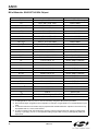
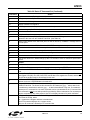
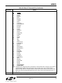
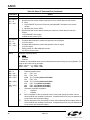
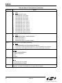
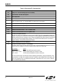
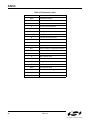
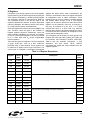
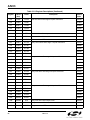
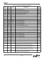
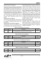
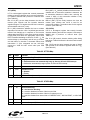
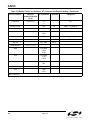
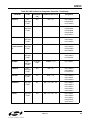
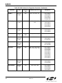
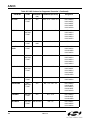
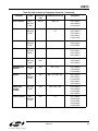
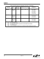
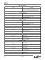
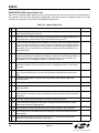
Table 88. AT Commands for Compliance Testing (Continued)
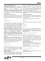
AT:Uaa,xxxx (aa is U-Register and xxxx is the hex value to be written) Write a U-Register
AT:Raa (aa is U-Register)
Read a U-Register
AT:R
Read all U-Registers
ATA
Send Answer Tone for 3 seconds
AT:U4D,0008 ATX0 ATDT
Send Calling Tone
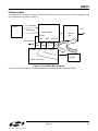
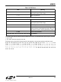
Connect test modem and remote modem through a telephone line
simulator. Configure test modem without protocol. Set test modem
S10 = 255. Connect phone in parallel to remote modem. Set remote
modem to desired modulation. Dial remote modem and connect.
Take parallel phone off-hook. Remove power from remote modem.
Test modem transmits indefinitely.
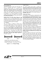
Transmit a specific modulation
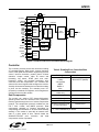
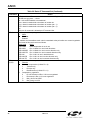
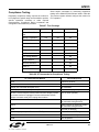
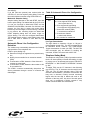
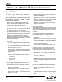
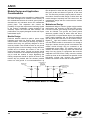
Homologation testing requires that the Si2493/57/34/15/
04 signal output be measured for each modulation and
data rate. The AT&T3 command establishes an analog
loopback connection to the phone line and places the
modem in data mode. The modulation is controlled by
the &H command. This command is insufficient for
homologation for several reasons:
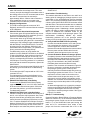
It is not possible to configure the output tone to be as
if from the answering or originating modem.
It is not possible to configure the data rate used in an
analoop connection within a given modulation.
Three data patterns need to be sent during output
testing: all marks, all spaces, and random data.
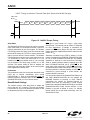
Once transmission with automatic data generation is
initiated, the modem goes off-hook and begins to
transmit the data in the modulation selected by the
existing &H command. Transmission continues until the
ATH command is sent after escape.
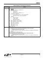
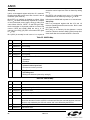
The data sent during &T4 and &T5 transmission tests is
controlled by the S40 register.
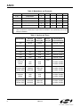
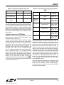
The data rate for &T4 and &T5 commands is controlled
by the existing &G command. In V.34 cases, where a
data rate may use multiple symbol rates, the symbol
rate is controlled by the S41 register. If an invalid
combination of data/symbol rate is selected, the modem
chooses a valid symbol rate. It is the responsibility of
the operator to select valid combinations for testing.
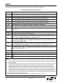
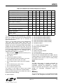
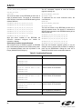
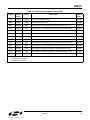
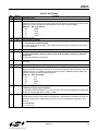
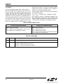
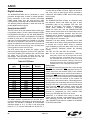
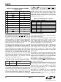
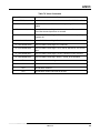
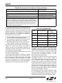
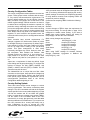
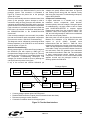
Table 89. Symbol/Data Rate
S41
V.34 Symbol Rate
0 (default) 2400 symbols/second
Allowable Data
Rates
2400—21600
1
2743 symbols/second
4800—26400
2
2800 symbols/second
4800—26400
3
3000 symbols/second
4800—28800
4
3200 symbols/second
4800—31200
5
3429 symbols/second
7200—33600
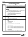
After the &T4 or &T5 command is issued and the
modulation output has begun, a result code stating
“CONNECT” followed by the data rate (as if the output
were an actual connection) is sent. The 300bps rate
does not give the speed after “CONNECT.” The &G4
command allows V.34/2400bps operation, and &G3
allows V.22bis/1200 bps operation.
The answer tone output must also be measured during
homologation testing. A bit in memory allows a
continuous answer tone to be output in the same way
as a continuous DTMF tone through the AT*Y1
command. After issuing the commands AT&H10 and
AT*Y2A (separate line required for each), a constant
answer tone is produced, and the modem is returned to
command mode. The tone continues until a character is
received or the S7 timer expires. After the command
has been terminated, the modem returns on-hook and
sends the “NO CARRIER” message.
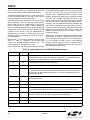
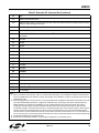
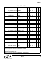
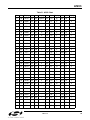
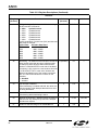
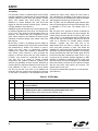
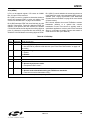
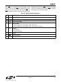
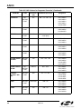
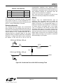
For homologation testing, it may be necessary to output
the V.29 modulation with transmit data. The +FTM
command includes additional codes given in Table 90 to
initiate output with the transmit data specified in S40.
122
Rev. 0.8