1
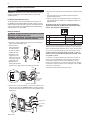
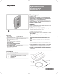
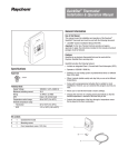
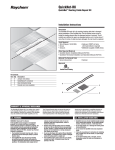
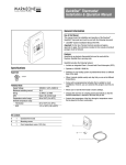
QuickStat-TC Installation & Operation Manual General Information Use of this Manual This manual covers the installation and operation of the Raychem QuickStat-TC thermostat and must be used with the following document: • QuickNet System Installation Manual (H57704) A F 2 Important: For the Tyco Thermal Controls warranty and agency approvals to apply, the instructions included in this manual and product packages must be followed. Features The QuickStat-TC is an electronic thermostat that must be used with the Raychem QuickNet floor heating mats. QuickStat-TC provides the following features: • Integrated Class A, Ground-Fault Circuit Interrupter (GFCI). Specifications • Operates at 120 V, 208 V, 240 V, 60 Hz. Approvals • Switches on your heating system at predetermined times on different days of the week. • Offers 4 periods each day that you can set at different temperatures. • Comes with a preprogrammed schedule that is suitable for most installations. However, you can customize this program any time you wish. Technical Data Supply voltage Maximum switching current GFCI Ambient setpoint range (A/AF mode) Floor setpoint range (F mode) Floor limit setpoint range (AF mode) Operating temperature range Storage temperature range 120 V, 208 V, 240 V, 60 Hz 15 A Class A, 5 mA trip level 40°F to 86°F (5°C to 30°C) 40°F to 104°F (5°C to 40°C) 40°F to 104°F (5°C to 40°C) • Allows you to reset the thermostat to factory settings. • Changes the start time of a heating period automatically so that the desired temperature is reached at the time that you set. • Multiple temperature control options so users can control the system based on floor temperature (F), ambient air temperature (A), or both (AF). • On/Off switch to turn off thermostat during summer months. 32°F to 120°F (0°C to 50°C) –4°F to 120°F (–20°C to 50°C) Kit Contents A 1 QuickStat-TC thermostat B 2 Mounting screws C 1 Floor temperature sensor 15 ft (4.6m) D 5 Wire nuts E 1 Screwdriver A D B C 400-115-052 E 2 QuickStat-TC Installation & Operation Manual Installation Important: This thermostat must be installed according to all national and local electrical codes. The installation must be performed by qualified personnel. Locating the floor temperature sensor The floor temperature sensor is installed under the floor surface. See the QuickNet System Installation Manual (H57704), Section 6, for more details. Perform the Sensor Resistance Test prior to terminating the floor sensor to the thermostat. See the QuickNet System Installation Manual (H57704), Section 7, for more details. 6.Push the excess length of the wires back inside the electrical junction box 7.Secure the power base to the electrical junction box using the provided mounting screws 8.Verify the settings of the configuration switches on the back of the control module. Default settings for the configuration switches are highlighted below. Important: If your system is installed underneath laminate or engineered wood flooring, you MUST use AF mode with the default settings. Note the factory default is AF mode. Wiring the thermostat WARNING: TURN OFF THE POWER TO THE CIRCUIT AT THE MAIN POWER PANEL TO AVOID ELECTRIC SHOCK. WARNING: SHOCK HAZARD. TO PREVENT SHOCK, THE QUICKNET FLOOR HEATING MAT MUST BE CONNECTED TO GROUND. 1.Remove the control module from the power base by loosening the captive screw underneath the base. 2.Connect the floor heating cold leads to the load wires (two inner wires) using the supplied wire nuts. Control module 3.Connect the power supply leads to the power base wires (two Air outer wires) using the vents supplied wire nuts. Power 4.Connect the floor base heating cold lead braid (ground) to the supply ground in the electrical junction box. Down 1 Display format °F/12 hr °C/24 hr 2 Early Start1 Enable Disable 3 Temperature control mode F AF 2 1 Note: If you wish to use only 2 periods, set periods “1 and 4” or periods “2 and 3”. Early Start will not work if you set periods “1 and 2” or periods “3 and 4”. 2 To select floor sensing mode, place the switch to the F position. To select floor sensing and ambient sensing mode, place the switch to the AF position and ensure that the remote temperature sensor is connected to the thermostat. To select the A mode, place the switch in the AF position and ensure that the remote temperature sensor is NOT connected to the thermostat. 9.Install the control module onto the power base. Power supply Supply ground Floor heating cold lead ground Load / Floor heating mat 5.Insert the floor sensor cable through one of the two openings on the power base and connect to terminals 1 and 2 (no polarity). Position the sensor cable such that it does not come in contact with the floor heating wires. Supply ground Floor heating cold lead ground 400-115-052 Up Early Start can be used in Automatic mode only. When this function is enabled, the thermostat calculates the optimal time to start heating in order to obtain the desired temperature by the set time. The thermostat re-assesses the start time daily based on the previous day’s results. Air vents Floor temperature sensor No. Configuration 3 QuickStat-TC Installation & Operation Manual To enable Daylight Savings Time: Thermostat Controlsand Display The following figure shows the thermostat controls. The thermostat has three temperature control modes: • AF mode: (Default mode) Controls the system based on the ambient air temperature and ensures that the floor temperature does not exceed the desired limits using an external floor temperature sensor • F mode: Controls the floor temperature using an external floor sensor • A mode: Controls the system based on the ambient air temperature (does not use floor sensor) GFCI test button Time and day display ON/OFF switch and GFCI reset 2 1 Appears when the setpoint is displayed Temperature display Date and time settings Mode display Percentage of heating time3 Preset temperature indicator Temperature control mode indicator Ground-fault indicator4 Temperature preset buttons Period display Program button Program clear button Mode selection / program exit Backlight button Temperature adjustment buttons 1 Place the switch in Standby to cut power to the heater when not in use (e.g., in the summer). This will not affect the time and temperature settings. 2 To reset the ground-fault protection, switch the thermostat to Standby and back to On. 3 The thermostat displays the percentage of heating time required to maintain the desired temperature. For example, is displayed when heating is activated 40 percent of the time. Display % of heating time 1 to 24% 25 to 49% 50 to 74% 75 to 99% 100% 4 GFI appears when the ground-fault protection has tripped. The display illuminates for 12 seconds when the backlight button is pressed. When either of the buttons are pressed, the display also illuminates. The setpoint temperature appears for 5 seconds, then the actual measured temperature is displayed. Date and Time Setting The first time you power up the thermostat, the time and date will flash and must be set. 1. Press the Hour button to set the hour. 2. Press the Min button to set the minutes. 3. Press the Day button to set the day. 4. Press Mode/Ret to exit. Daylight Savings Time The QuickStat-TC can automatically adjust for Daylight Savings Time. When this function is enabled, the thermostat switches to Daylight Savings Time on the second Sunday of March and to normal time on the first Sunday of November. 1. Press and hold the Day button for 3 seconds until DLS appears on the screen. buttons to toggle between 2. Press the up/down On (enabled) and Off (disabled). 3. Press the Day button. The year setting is displayed. 4. Use the up/down buttons to set the current year. 5. Press the Day button. The month setting is displayed. 6. Use the up/down month. buttons to set the current 7. Press the Day button. The date setting is displayed. 8. Use the up/down buttons to set the current date. 9. Press Mode/Ret to exit. Ground-Fault Protection The QuickStat-TC has a built-in GFCI (5 mA trip level). This protects users against risks of electrocution by cutting off the power to the floor heating system when the leakage current exceeds 5 mA. If a ground-fault has occurred, the TEST light on the top of the thermostat will illuminate red and GFI will appear on the screen. Testing the GFCI Users should test the GFCI after the installation of the QuickNet floor heating system is complete to ensure that the ground-fault protection is in working order. Users should test the GFCI on a monthly basis thereafter. 1.The GFCI can only be tested if the thermostat has a heating demand. Increase the setpoint temperature above the current measured temperature. Wait several seconds to allow the thermostat to adjust to the new set point and the heating symbol appears. 2.Press the TEST button. The test is successful if the TEST light on top of the thermostat illuminates red and GFI appears on the screen. The test has failed if the TEST light on top of the thermostat does not illuminate red. In this case, turn the power off to the floor heating system and check the installation of the thermostat. Resetting the GFCI If the GFCI has tripped, reset it by switching the thermostat to Standby and back to On. The TEST light on top of the thermostat will go off. If the GFCI trips in normal operation without pressing the TEST button, there could be a ground-fault. To check whether it is a ground-fault or nuisance tripping, reset the GFCI. If the GFCI does not trip after the reset, it was nuisance tripping and the system is functioning properly. If the GFCI trips again after the reset, there is a ground-fault. The user should contact a qualified electrician to troubleshoot the issue. Note: This function is disabled (default setting) when the clock loses its setting 400-115-052 4 QuickStat-TC Installation & Operation Manual Modifying the Schedule Programming Programming The QuickStat-TC comes with a pre-programmed default schedule. The schedule consists of 4 periods per day which represents a typical week day. Period Description Associated temperature setting Away from home Return home Sleep 3. Press Hour and Min to set the start time of the selected period, or press Clear if you want to skip the period (--:-- is displayed). Default Programming Note: If you wish to use only 2 periods, set periods “1 and 4” or periods “2 and 3”. Early Start will not work if you set periods “1 and 2” or periods “3 and 4”. The following shows the pre-programmed default schedule in the QuickStat-TC. TU WE TH FR SA SU 8:30A 8:30A 8:30A 8:30A 8:30A --:-- --:-- 4. Press Pgm to select another period, or press Day to select another day. They repeat step 3. Repeat steps 3 & 4 until programming is complete. 5:00P 5:00P 5:00P 5:00P 5:00P --:-- --:-- 5. Press Mode/Ret to exit the programming mode. 6:00A 6:00A 6:00A 6:00A 6:00A 6:00A 6:00A 11:00P 11:00P 11:00P 11:00P 11:00P 11:00P 11:00P The Comfort ( ) temperature is used in periods 1 and 3 and the Economy ( ) temperature is used in periods 2 and 4. For example, when the period changes from 1 to 2, the setpoint automatically changes from Comfort ( ) temperature to Economy ( ) temperature. Preset Temperatures The QuickStat-TC comes with 3 preset temperatures shown as Comfort ( ) temperature, Economy ( ) temperature and Vacation ( ) temperature. The following table shows the intended use and the default setting of each preset temperature. Icon Intended use Comfort (when at home) Economy (when asleep or away from home) Vacation (during prolonged absence) Operating Modes The QuickStat-TC has three operating modes: Automatic Mode In this mode, the QuickStat-TC follows the programmed schedule. To place the QuickStat-TC in this mode: 1. Press the Mode/Ret button until the play. icon appears on the dis- 2. To disable Automatic mode, press the Mode/Ret button to change . the mode to Manual mode A/AF modes F mode Temporary Manual Override (in Automatic Mode 70°F (21°C) 82°F (28°C) Users can temporarily override the scheduled programming of the QuickStat-TC. The new temperature setpoint will be used until the beginning of the next period. To temporarily override the QuickStat-TC: 63°F (17°C) 68°F (20°C) 50°F (10°C) 50°F (10°C) 1. Set the desired temperature using the , or button, while the thermostat is in the 1. Press the Automatic mode, to the new desired setpoint. Once the new setpoint is accepted, the icon will begin to flash. Manual Mode buttons. 2. Press and hold the corresponding preset button ( until the corresponding icon is displayed. ) 2. To cancel the temporary override, press the Mode/Ret button. Users can also change a preset temperature by: , , or Floor Temperature Limit (AF Mode Only) The default temperature limits are 41°F to 82°F (5°C to 28°C). Important: If your system is installed underneath laminate or engineered wood flooring, you MUST use AF mode with the default settings. Note the factory default is AF mode. 400-115-052 1. Press Pgm to access the programming mode. Period 1 will be displayed. 2. Press Day to select the day to program for the selected period. To select the entire week, press and hold the Day button for 3 seconds until all days are selected. Wake-up Period Setting MO The user can change the programming to better meet their lifestyle. To do so: ) In this mode, the programmed schedule is not used and the setpoint temperature must be set manually. To place the QuickStat-TC in this mode: 1. Press the Mode/Ret button until the display. 2. Set the temperature using the , icon appears on the or button. 3. To disable Manual mode, press the Mode/Ret button to change the . mode to Automatic mode 5 QuickStat-TC Installation & Operation Manual Vacation Mode In this mode, the QuickStat-TC is set to the Vacation setpoint temperature and will override all programming until Vacation mode is disabled. To place the QuickStat-TC in this mode: 1. Press the button, and the icon appears on the display. 2. To disable Vacation mode, press the Mode/Ret button to change the or Manual . mode to Automatic To reset the QuickStat-TC to factory default settings: 3. Turn the thermostat to Off. 4. Press the up button and switch the thermostat On. 5. After the thermostat setup is completed, release the up button . Error Messages The measured temperature is below the thermostat’s display range. Heating is activated. The measured temperature is above the thermostat’s display range. Heating is deactivated. Verify the floor sensor connection to the thermostat. 400-115-052 6 Tyco, QuickNet and QuickStat are registered and/or unregistered trademarks of Tyco Thermal Controls LLC or its affiliates. Worldwide Headquarters Tyco Thermal Controls 7433 Harwin Drive Houston, TX 77036 USA Tel: 800-545-6258 Tel: 650-216-1526 Fax:800-527-5703 Fax:650-474-7711 [email protected] www.tycothermal.com Canada Tyco Thermal Controls 250 West St. Trenton, Ontario K8V 5S2 Canada Tel: 800-545-6258 Fax:800-527-5703 Important: All information, including illustrations, is believed to be reliable. Users, however, should independently evaluate the suitability of each product for their particular application. Tyco Thermal Controls makes no warranties as to the accuracy or completeness of the information, and disclaims any liability regarding its use. Tyco Thermal Controls' only obligations are those in the Tyco Thermal Controls Standard Terms and Conditions of Sale for this product, and in no case will Tyco Thermal Controls or its distributors be liable for any incidental, indirect, or consequential damages arising from the sale, resale, use, or misuse of the p roduct. Specifications are subject to change without notice. In addition, Tyco Thermal Controls reserves the right to make changes—without notification to Buyer—to processing or materials that do not affect compliance with any applicable specification. 400-115-052 © 2011 Tyco Thermal Controls LLC H58517 04/11 QuickStat-TC Installation & Operation Manual