1
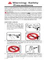
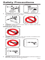
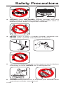
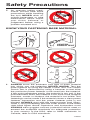
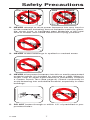
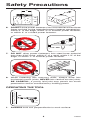
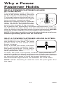
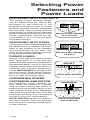
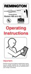
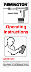
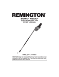
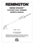
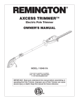
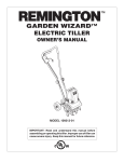
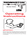
®
REMINGTON R300
S
F
Model R300
pOWDEr aCtUatED tOOL
™
manUFaCtUrErS´ nStItUtE InC.
Operating
Instructions
Important:
Read all instructions and warnings found in this manual
and on power load packaging before operating your
powder actuated tool. This manual should always accompany the tool and be transferred with it upon change
of ownership.
Index
Warning: Safety Precautions............................................ 3-11
Why A Fastener Holds..........................................................12
Selecting Fasteners and Power Loads.................................13
Operation........................................................................ 14-16
Parts List...............................................................................17
Accessories..........................................................................17
Barrel Replacement..............................................................18
Troubleshooting Guide....................................................19, 20
Application Chart............................................................20, 21
Replacement Parts and Accessories...................................22
Technical Service.................................................................22
Repair Service......................................................................22
Parts Centrals.......................................................................23
Limited Warranty...................................................................24
REMINGTON®
Model R300
The Remington® Model R300 is designed for use with Remington® .22 caliber, Type A, neck-down crimped power loads and
Remington® Power Fasteners. Remington® Power Fasteners
are manufactured from special steel and heat treated to produce a very hard, yet ductile, fastener.
The Remington® Model R300 is equipped with two safety
devices; a safety ON/OFF switch next to the trigger and a
spring-compression muzzle that must be fully depressed for
the tool to fire.
Spall
Shield*
Power Fastener*
Power Load*
REMINGTON R300
S
F
Barrel Assembly
Muzzle
Trigger
S
F
Safety ON/OFF
Switch
Recommended
Approved Eye
Protection*
* Not provided with tool.
119586
Warning: Safety
Precautions
The following pages contain detailed warnings, cautions, and
rules of safe operation. Read carefully and become familiar
before operating to avoid serious injury. We expressly disclaim
any liability for any injury to persons or damage to property
which result from your failure to take the precautions contained
in this manual.
WARNING: This tool is designed only for use by qualified
operators. Qualification is obtained through a thorough understanding of the Safety Precautions and operating instructions
as defined in this operating manual. NOTE: The labor regulations of many states require that the operator of this tool on
a job site be thoroughly trained and certified for competence
prior to operating this tool. For certification procedures, call:
DESA Power Tools™ Technical Services Department, 1-800858-8501 (English only) or visit www.desatech.com.
BEFORE USING
1.ALWAYS handle the tool
as if it were loaded. Before
starting work, check that
the tool is unloaded and
the muzzle is clear. NEVER
load a tool unless it is going
to be used.
?
?
F
DEF
ECT
IVE
F
2.ALWAYS inspect to make sure the tool is working properly.
If the tool does not work properly, remove from service and
tag DEFECTIVE. DO NOT use the tool again until it has
been properly repaired.
3. Operators and bystanders must ALWAYS wear goggles
and ear protection which meet or exceed the accepted
standards for adequate protection in your country. In the
USA, refer to ANSI standards. In Canada, refer to CSA
standards.
119586
Safety Precautions
WarnInG
pOWDEr
aCtUatED
tOOLS
In USE
!
4.ALWAYS clear the work area on all sides and post appropriate warning signs on job sites.
S
5.ALWAYS make sure the work area is clean from loose
material and debris.
HANDLING THE TOOL
1.NEVER place your hand over the muzzle. Accidental discharge can cause serious injury.
2.NEVER place your finger on the trigger until the muzzle of
the tool is against the work surface.
119586
Safety Precautions
F
POWE
LOAD POWER
LOADS
3.ALWAYS store UNLOADED powder actuated tool and
power loads in a locked container. Keep power loads of
different power levels in separate containers.
4.NEVER carry or pass a loaded powder actuated tool.
NEVER point a powder actuated tool at anyone.
S
F
5. If the tool is dropped, inspect for damage and repair it before
continuing to work. NEVER use a damaged tool.
6.ALWAYS take precautions to maintain your balance while
operating a powder actuated tool.
119586
Safety Precautions
7. An operator taking medication should take extra
precautions while handling
the tool. NEVER drink alcoholic beverages or take
medications which impair
your vision, balance, or
judgement before using a
powder actuated tool.
?
?
?
KNOW YOUR FASTENING BASE MATERIAL
?
?
?
?
CENTER
PUNCH TEST
Point
flattens
Sinks in
with
average
hammer
blow
tOO SOFt
tOO HarD
Start
Surface
shatters
1
GRAY
2
BROWN
3
GREEN
4
YELLOW
tOO BrIttLE
1.ALWAYS know the thickness and type of base material
into which you are fastening. NEVER GUESS. Test the
base material by using the Center Punch Test. The Center
Punch Test is performed by using a hammer to test drive
the particular power fastener to be used into the material.
If the point penetrates easily, the material is too soft. If the
point becomes blunt, the material is too hard. If the material
fractures, cracks or shatters, the material is too brittle. Test
fastenings can be made if the material shows a clear power
fastener impression and the power fastener point is not
blunted. ALWAYS start with the lowest power load (GrayLevel 1) and proceeding with the order shown in the lower
right-hand figure above. Operators and bystanders must
ALWAYS wear goggles and ear protection which meet or
exceed the accepted standards for adequate protection
in your country. In the USA, refer to ANSI standards. In
Canada, refer to CSA standards.
119586
Safety Precautions
CAST IRON
tILE
GLASS
BrICK
2.NEVER attempt to drive power fasteners into very hard or
brittle materials including, but not limited to cast iron, glass,
tile, stone, brick, or hardened steel. Materials of this type
tend to shatter and create hazard from flying particles.
3.NEVER make fastenings in spalled or cracked areas.
4.NEVER drive power fasteners into thin or easily penetrated
material unless it is backed by concrete or steel. When in
doubt, such as when base material is concealed, conduct
a Center Punch Test (See page 6). Check continually to
avoid fastening into unsuitable material, especially in older
buildings.
5. DO NOT fasten through or within 1/2" of predrilled or prepunched holes.
119586
Safety Precautions
3"
3"
3"
3"
1X
3X
6. DO NOT drive power fasteners into concrete less than three
times as thick as the intended power fastener penetration,
within 3" of the edge, within 3" of another power fastener,
or within 3" of a failed power fastener.
WELD
1"
1/2"
3/16" mIn
tOO tHIn
7. DO NOT drive power fasteners into steel base material
less then 3/16" thick, within 2" of a weld, within 1/2" of the
edge, or within 1" of another power fastener.
NO
YES
8. When fastening into masonry walls, always drive into
horizontal mortar joints, NEVER into vertical mortar joints.
BE CAREFUL, a poorly laid joint may permit too much
penetration and/or unsatisfactory holding power.
OPERATING THE TOOL
90˚
1.ALWAYS hold tool perpendicular to work surface.
119586
Safety Precautions
30
WATER
2. Should the tool fail to fire, hold the muzzle firmly against
the work surface for 30 seconds. Release the trigger and
remove pressure on the tool while holding the muzzle
against the work surface. Again press the tool firmly against
the work surface and pull the trigger. If the tool still fails to
fire, hold the tool firmly against the work surface for another
30 seconds before unloading and carefully discarding the
misfired power load into water or oil.
Spall
Shield
3.ALWAYS use the spall shield when driving directly into
concrete or steel. ALWAYS wear eye protection.
GAS
GASOLINE
OLINE
4.NEVER use a powder actuated tool in an explosive or
flammable atmosphere or when non-sparking tools are
required.
POWER LOADS AND Power FASTENERS
Er
pOWDS
LOa
Er
pOWDS
LOa
1. NEVER leave unfired power loads on floors or work surfaces.
119586
Safety Precautions
Start
22
CALIBER
2
BROWN
3
GREEN
5
4
3
2
4
YELLOW
6
7
1
1
8
9
10
11
12
NICKEL
BRASS
1
GRAY
NOTE:
Failure to start with
the lowest power level
can result in overdrive
condition and will result in damage to tool
(see page 13).
2. Remington® Power Loads are available in four power levels with
gray (1) being the lowest power level and yellow (4) being the
highest power level. start with the lowest power level (gray-level
1) and increase until a proper fastening is made (see page 13,
Selecting Power Fasteners and Power Loads).
Er
pOWDS
LOa
Er
pOWDS
LOa
3.NEVER use power loads in firearms.
pOWEr
LOaDS
OnLY
4.NEVER carry power fasteners or other hard objects in the
same pocket or container with power loads.
YELLOW?
BrOWn?
GrEEn?
GraY?
5. A color blind person must take extra precautions to prevent
the chance of mixing the power loads of various levels.
10
119586
Safety Precautions
6. Power fasteners are a permanently installed fixture. An
act of demolition is required for their removal. Appropriate
safety precautions must be taken.
Head
Shank
plastic Flute
7.NEVER use common nails or other materials as fasteners. Remington® Power Fasteners are manufactured from
special steel and heat treated to produce a very hard, yet
ductile, fastener.
8.NEVER pry a power load out of the chamber. Prying can
discharge the load causing serious injury (see Troubleshooting Guide on pages 19 and 20).
LOAD
1
UNLOAD
2
2
F
1
F
9.ALWAYS insert the power fastener first, then the power
load. If work is interrupted for any reason, ALWAYS remove
the power load before removing the power fastener (see
page 15, item 8).
119586
11
Why a Power
Fastener Holds
WHY A POWER FASTENER HOLDS
IN CONCRETE
The compression bond of the concrete to the power fastener accounts
for the majority of the holding power.
The power fastener displaces the concrete which tries to return to its original
form causing a squeezing effect.
Maximum holding power is achieved
when the depth of penetration produces a bond on the power fastener
equal to the strength of the concrete.
As a general rule, penetration should be approximately 1" to 1 1/4"
into the base concrete. Make sure the concrete is at least three
times as thick as the intended power fastener penetration. NEVER
have the power fastener point protrude thru the concrete.
NOTE: Concrete needs to cure for 28 days before maximum
fastening holding power will be achieved.
WHY A POWER FASTENER HOLDS IN STEEL
Holding power in steel depends on
the elasticity of the steel. The steel
pushes back on the shank of the
power fastener.
Drop a marble into water; the water
parts, the marble continues down,
the water closes back. This is similar
to the reaction when a power fastener penetrates steel.
In steel, the point of the power fastener must penetrate completely through for highest holding power. If the power fastener
does not penetrate, the spring action of the steel pushes back
on the point and tends to force the power fastener out.
Recommended applications are between 3/16-3/8" steel.
NOTE: When fastening in steel be sure the point goes thru
the steel.
12
119586
Selecting Power
Fasteners and
Power Loads
FASTENING INTO CONCRETE
The proper power fastener length
can be determined by adding the
thickness of the material to be
fastened and the amount of power
fastener that will actually penetrate
the concrete. The concrete must be
three times as thick as the intended
power fastener penetration. In most
cases, penetration should be approximately 1" to 1 1/4" into the base
concrete material.
Wood or Non-Metals
To Concrete
FASTENING INTO STEEL
The proper power fastener length can
be determined by adding the thickness of the material to be fastened
and the thickness of the steel. The
point of the power fastener must go
completely through the steel.
Wood or Non-Metals
To Steel
POWER LOADS
Always start with the lowest power
level (gray-level 1). If the first test
power fastener does not penetrate to
the desired depth, move to the next
highest power level (brown-level 2).
Increase until a proper fastening is
made. IMPORTANT: Damage to the
tool will result if the above instructions are not followed (see illustrations to right and lower right).
OVERDRIVEN POWER
FASTENERS AND PISTON
An overdriven power fastener results when too strong of a power
load is used causing the piston to
extend past the muzzle. Move to the
next lightest power load. Repeated
overdrive will damage your tool. By
avoiding overdrive, you can extend
the life of your tool considerably.
NOTE: NEVER fire the tool without
a power fastener. This can damage
the tool and/or cause possible injury
to the operator.
119586
13
RIGHT
Flush With Surface
OVErDrIVE
Piston Extended
Out of Muzzle
Operation
S
F
Safety ON
1. Always place safety ON/OFF switch in the SAFETY ON
position before inserting power fastener and power load.
2. Grasp muzzle and slide barrel forward rapidly until it stops.
This sets piston into firing position and opens the chamber.
3. Insert power fastener into muzzle of tool, head end first. Push
the power fastener until point is even with end of tool. ALWAYS
load the power fastener first, then the power load.
4. Select the proper Remington® Power Load (see Application
Chart on pages 20 and 21) and insert into the chamber until
it stops. NOTE: Failure to start with the lowest power level
can result in overdrive condition and will result in damage
to the tool (see page 13).
14
119586
Operation
5. Push barrel into housing to the closed position.
90˚
6. Place the muzzle of tool perpendicular to work surface
without tilting the tool. Push tool against work surface until
sliding action of barrel stops.
S
F
Safety OFF
7. Before squeezing trigger, rotate safety ON/OFF switch to
the SAFETY OFF position. Squeeze trigger to set power
fastener. Be sure to keep pressure on tool during this operation.
IMPORTANT: When tool is not in use, always rotate
safety ON/OFF switch to the SAFETY ON position.
8. After fastening is made, slide barrel forward rapidly. This
motion ejects the spent power load and resets the piston
for the next fastening. Make sure spent load has ejected
from tool.
119586
15
Operation
30
WATER
9. Should the tool fail to fire, hold the muzzle firmly against
the work surface for 30 seconds. Release the trigger and
remove pressure on the tool while holding the muzzle
against the work surface. Again press the tool firmly against
the work surface and pull the trigger. If the tool still fails to
fire, hold the tool firmly against the work surface for another
30 seconds before unloading and carefully discarding the
misfired power load into water or oil.
PISTON OVERDRIVE
If the tool does not open after firing and the piston is 1/2 inch or
more out of the muzzle:
1. Strike muzzle end of R300 against hard surface to force
piston back into muzzle.
2. Eject the power load (See step 8 of Operation).
OVERDRIVE
CARE OF YOUR R300
Clean your R300 after each day’s use. Clean chamber with
accessory wire brush, part number 056485 (Not included with
tool). Apply good quality penetrating lubricant spray (such as
WD-40) sparingly and wipe dry.
NOTE: The labor regulations of many states require that the
operator of this tool on a job site be thoroughly trained and certified for competence prior to operating this tool. For certification
procedures, call: Technical Services Department, 1-800-8588501 (English only) or visit www.desatech.com.
16
119586
Parts List
17
16
8
7
5
6
13
9
2
3
11
2
1
18
20
15
14
4
10
19
Key
No.Part No.
1
300001
2
300110
3
300101
4
300010
5
300104
6
300105
7
300106
8
300107
9
300108
10
300201
11
300210
12
479601
13
479602
14
479603
15250604
16
479605
17
479606
18
479607
19
479300
20
479205
Description
Qty.
Handle Screw2
Handle
1
Safety Switch
1
Tang Cap Screw
1
Safety Switch Screw
1
Trigger
1
Trigger Spring
1
Trigger Lock Nut
1
Trigger Screw
1
Receiver Stop
1
Receiver
1
Breech
1
Breech Spring
1
Sear
1
Sear Spring
1
Firing Pin
1
Firing Pin Spring
1
Pin Stip
1
Barrel Assembly
1
Tang
1
ACCESSORIES
Part No.
101320-01
056415
056485
056486
501801
Description
Spall Sheild
Goggles
Brush, 1/4"
Brush, 5/8"
Hex Wrench, 3mm
IMPORTANT: Do not use key numbers when ordering service
parts. Always order components by part number and description. Include Model and Serial numbers.
119586
17
Barrel Replacement
WARNING: Never disassemble, replace barrel, clean,
or assemble a powder actuated tool while it is loaded.
A
B
1. Unscrew knurled tang nut
(A). Slide barrel assembly
(B) out and remove tang (C),
then remove barrel assembly (B) from receiver (D).
C
B
D
S
B
E
2. If tool has been overdriven, tap piston (E) on a hard surface
until the piston is pushed back into the muzzle. Inspect the
barrel assembly (B) and replace if damaged.
B
3. To assemble, push piston
(E) all the way into barrel
(B) using a screwdriver (G).
Slide the barrel assembly
(B) into the receiver (D).
Turn barrel (B) to line up
tang slot (F) with tang (C).
Insert tang (C) into tang slot
(F). Firmly tighten knurled
tang nut (A).
18
D
B
F
A
C
119586
Troubleshooting Guide
PROBLEM
POSSIBLE
CAUSE
REMEDY
Piston hangs Tool overdriven.
out of muzzle.
Tap piston on a hard
surface until piston is
pushed back into the
muzzle (see Overdriven
Fastener, below).
Piston not properly Remove barrel assemassembled in rela- bly. Follow instructions
tion to barrel screw. for barrel replacement
(see page 18). Replace
all damaged or missing
parts.
Broken piston.
Overdriven fas- Excessive power.
tener.
Replace barrel assembly or take tool to your
distributor.
Change either to next
lower powder load or next
longer length fastener.
Piston jammed. Overdriving of fas- Remove barrel assemtener (see above). bly. Follow instructions
for barrel replacement
(see page 18). Replace
other parts if damaged.
Expended load Dirty or damaged Clean chamber. If loads
will not extract. chamber.
will not chamber with
slip-fit or extraction difficulties continue, take
tool to your distributor.
Broken ejector.
Replace barrel assembly or take tool to your
distributor.
Reduction or Piston not returning Barrel must be snapped
loss of power to full rear position. to the full extended position to properly position
piston against breech.
Worn piston ring or Replace barrel assembroken piston.
bly or take tool to your
distributor.
Tool does not Misassembled or Remove breech and
completely de- damaged breech check all parts for correct
and firing pin parts. fit assembly.
press.
119586
19
Troubleshooting Guide
PROBLEM
POSSIBLE
CAUSE
REMEDY
Tool does not Failure of tool to See data listed under
fire.
d e p r e s s c o m - Tool does not completely
depress, above.
pletely.
Dirt build-up on
breech not allowing proper penetration of firing
pin.
Check firing pin indentation on cartridge. Clean
breech, breech face, sear
and firing pin. Replace
worn or damaged parts.
Safety Switch is in Rotate Safety Switch to
OFF position.
ON position
Opening and Lack of proper Inspect and clean comclosing of bar- cleaning.
plete tool. Replace worn
rel or pushing
or damaged parts.
down on the
tool, etc. is not
smooth but is
rough or binds.
Application Chart
Power load and power fastener application information.
For fastening
this:
to this:
Power fastener
length
20
Power load
color
119586
Application Chart
Power load listings are recommendations only. If you are in
doubt, try a test fastening using the next lightest power load.
Power fasteners and power loads are available in blister packs
of 25 and cartons of 100.
IMPORTANT
• Recommended for use with Remington® power loads and
power fasteners.
• If power fastener goes below the top surface of the board, use
penetrating control disc (see illustration below) or washered
SPW-type power fasteners.
• Operators and bystanders must ALWAYS wear goggles and
ear protection which meet or exceed the accepted standards
for adequate protection in your country. In the USA, refer to
ANSI standards. In Canada, refer to CSA standards.
* Use power fastener with penetration control disc, part
number 015549.
IMPORTANT
This tool is designed to use .22 caliber neck-down crimped
loads, power levels 1 (gray) through 4 (yellow).
5/8"
Neck-Down Crimped
Power Load
Straight Wadded
Power Load
CAUTION: Do not use any load other
than the .22 caliber neck-down crimped load.
Other types of loads will cause load-ejection
problems.
.22 CALIBER Type A, neck-down crimp loads for powder
actuated tools
Load
Color Code
Stock
Level
Load
Case
NumberNumber Strength Body Head
A22C1
1
A22C22
A22C3
3
A22C4
4
119586
light
medium
heavy
extra heavy
21
brass
brass
brass
brass
Gray
Brown
Green
Yellow
Replacement Parts
And Accessories
WARNING: Use only replacement parts and accessories described in this manual. Use of other parts or
accessories could damage tool or injure operator.
For original replacement parts and accessories, contact your
nearest Authorized Dealer or Authorized Service Center for this
product. If they can not supply the part or accessory, contact
your nearest Parts Central listed on page 23. Each Authorized
Dealer, Authorized Service Center, and Parts Central is independently owned and operated.
See page 17 for an Illustrated Parts List.
If you need additional referral information, contact our Technical
Service Department (see Technical Service).
In Canada call 1-800-561-3372 for parts information.
Technical Service
You may have further questions about assembling, operating,
or maintaining this product. If so, you can visit our Technical
Service web site at www.desatech.com or contact our Technical Service Department at 1-800-858-8501 (English Only).
You may also write to:
DESA Power Tools™
P.O. Box 90004
Bowling Green, KY 42102-9004
ATTN: Technical Service Power Tools
When contacting DESA Power Tools™, have ready
• Your Name
• Your Address
• Your Phone Number
• Model Number of Product
• Date of Purchase (Include copy of receipt for written requests).
Repair Service
Note: Only use original replacement parts. This will protect your
warranty coverage for parts replaced under warranty.
Each Authorized Service Center is independently owned and
operated.
Warranty Service
If product requires warranty service, return it to nearest Authorized
Service Center. You must show proof of purchase. If faulty materials
or workmanship caused damage, we will repair or replace product
without charge. Note: Normal wear, misuse, abuse, neglect, or
accidental damage is not covered under warranty.
Non-Warranty Service
If product requires service, return it to nearest Authorized Service
Center. Repairs will be billed to you at regular repair list prices.
For additional Service Center or warranty information, call
1-800-858-8501 (English only) or visit our Technical Service
web site at www.desatech.com.
119586
22
Parts Centrals
Ray’s Portable Heater Service
3191 Myers Road
Camino, CA 95709-9550
530-644-7716
Tool & Equipment Service
Solutions, LLC
5 Manila Drive
Hamden, CT 06514-0322
203-248-7553
1-800-397-7553
Grainger Parts Operations
1657 Shermer Road
Northbrook, IL 60062-5362
708-498-5900
1-800-323-0620
www.grainger.com
Portable Heater Parts
342 North County Road 400 East
Valparaiso, IN 46383-9704
219-462-7441
1-800-362-6951
www.portableheaterparts.com
[email protected]
[email protected]
FBD
1349 Adams Street
Bowling Green, KY 42103-3414
270-846-1199
1-800-654-8534
[email protected]
Lyons & Lyons Sales Co. Inc.
Glen Arm Road
Glen Arm, MD 21057-9454
410-665-6500
1-800-333-5966
[email protected]
Master Part Distributors
1251 Mound Avenue NW
Grand Rapids, MI 49504-2672
616-791-0505
1-800-446-1446
www.masterparts.net
Hance Distributors, Inc.
12795 16th Avenue North
Plymouth, MN 55441-4556
763-559-2299
www.hanceco.com
Automotive Equipment Service
1651 E. Kansas City Road
Olathe, MO 66061
816-531-9144
1-800-843-3546
www.aes-lawnparts.com
119586
Bowden Electric Motor Service
1681 S. Wesleyan Blvd.
Rocky Mount, NC 27803
252-446-4203
East Coast Energy
10 East Route 36
West Long Branch, NJ 07764-1501
1-800-755-8809
Forrest Lytle and Sons, Inc.
740 West Galbraith Road
Cincinnati, OH 45231-6002
513-521-1464
Bortz Chain Saw Shop
Road #2, Box 64A
Oley, PA 19547-9412
610-987-6452
21st Century
2950 Fretz Valley Road
Perkasie, PA 18944-4034
215-795-0400
1-800-325-4828
La Ports
2444 N 5th Street
Hartsville, SC 29550-7704
843-332-0191
MTA Distributors
555 Hickory Hills Blvd.
Nashville, TN 37189-9244
615-299-8777
1-800-264-0225
Webbs Appliance Center
1519 Church Street
Nashville, TN 37203-3004
615-329-4079
1-800-899-4079
Industrial Hardware
4109 Bainbridge Blvd.
Chesapeake, VA 23324-1403
804-543-2232
1-800-788-0008
[email protected]
Mills Lawn and Garden
928 Commonwealth Place
Virginia Beach, VA 23464
757-361-9293
www.mills-parts.com
Tuco Industrial Products
5223 180th Street SW
Suite 4A-1
Lynnwood, WA 98037-4506
425-743-9533
1-800-735-1268
www.tucoheat.com
23
Limited Warranty
DESA Power Tools™ warrants the Remington® Model R300
against defects in materials and workmanship for a period of
one (1) year (90 days for reconditioned unit) from the date of
purchase. The bill of sales or proof of purchase must be presented at the time a claim is made under this warranty.
If within one (1) year from the purchase date this Powder
Actuated Tool fails due to a defect in material or workmanship,
DESA Power Tools™ will repair or replace the tool at DESA
Power Tools™ option. To obtain service under this warranty,
contact DESA Power Tools™ at the number/address listed below. You must have the Serial Number, Model Number, date of
purchase and indicate the type of problem being experienced.
DESA Power Tools™ will send replacement part(s), repair,
or replace the tool at DESA Power Tools™ option. However,
this warranty does not cover failures caused by misusing or
abusing the product (for proper use of this product, read and
understand the operating instructions in this owners manual).
Repairs made because of misuse, abuse, negligence, or accident will be charged for at regular repair prices. Power loads
and power fasteners are not covered.
This express and limited warranty is the only warranty on this
product, and to the full extent permitted by law there are no
other warranties, express or implied, including warranties of
merchantability and/or fitness for a particular purpose which
extend beyond the terms of this express and limited warranty.
To the full extent permitted by law, the liability of DESA Power
Tools™ for personal injury, property damage, or any other
damage whatsoever, including consequential and incidental
damages, arising from the sale or use of this product shall not
exceed the purchase price of this product.
This warranty gives you specific legal rights, and you may also
have other rights which vary from state to state.
In U.S.A., contact:
In Canada, contact:
P.O. Box 90004
Bowling Green, KY 42102-9004
82 Akron Road
Toronto, Ontario
M8W 1T2
1-800-561-3372
Fax: 1-800-561-8003
www.desatech.com
U.S.A. ONLY
For Technical Assistance on Your
Remington® Powder Actuated Tool Or
For Certification Procedures, Call
Technical Services Department
1-800-858-8501 (English only)
Or Visit www.desatech.com.
24
119586