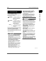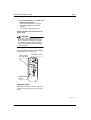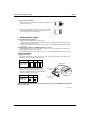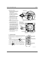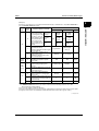
1
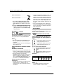
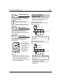
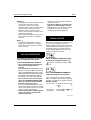
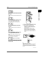
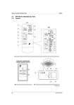
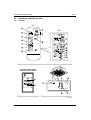
Remote Controller (Wireless Type)
O H 0 8 -1
2.2
B RC7 E 6 1W / B RC7 E 6 5 (F or F X F )
2.2.1
O pera tion
1-1
1
O N
O FF
8
1-2
3
H
M
L
D O W N
10
C
O N
U P
6
FAN
H
4
L
T E MP
T IME
11
C
h r.
2
M
O FF
UP
9
DOW N
FAN
h r.
13
R E S E R V E CA N CE L
h r.
5
T IME R
12
MO D E
15
h r.
TEST
7
S W IN G
14
16
TEST
TEST
17
1
CO O L /H E A T CH A N G E O V E R
RE M O TE CO N TRO L S WITCH
21
20
19
24
18
25
23
1-3
22
2
3P A 63363-24W -0
28
Co n tro l S y s te m s
OH08-1
Remote Controller (Wireless Type)
Read th e follow ing c au tions c arefu lly and
u se you r eq u ipment properly.
There a re three k ind s of sa fety c a u tions a nd
tip s listed here a s follow s:
WARNING ....... Imp rop er ha nd ling c a n
lea d to su c h seriou s c onseq u enc es a s d ea th or
sev ere inju ry.
CAU TION ........ Imp rop er ha nd ling c a n
lea d to inju ry or d a ma g e.
It c ou ld a lso ha v e seriou s
c onseq u enc es u nd er
c erta in c ond itions.
NOTE
....... These instru c tions w ill
ensu re p rop er u se of the
eq u ip ment.
B e su re to follow these imp orta nt sa fety c a u tions.
K eep th ese w arning sh eets h and y so th at
you c an refer to th em if need ed .
Also, if this eq u ip ment is tra nsferred to a new
u ser, ma k e su re to ha nd ov er this u ser’s ma nu a l to the new u ser.
WARNING
D o not ex pose you rself d irec tly to th e
c ool air c u rrents too long nor allow th e
air in th e room to b ec ome too c old .
Doing so ma y ma k e you feel sic k or d a ma g e you r hea lth.
If you d etec t any ab normality (su c h as th e
smell of fire), tu rn off th e pow er and c ontac t you r d ealer for instru c tions.
If you k eep u sing the a ir c ond itioner
u nd er these c ond itions, it w ill ev entu a lly
b rea k d ow n, a nd c ou ld c a u se elec tric
shoc k s or c a tc h fire.
Ask you r d ealer to install you r eq u ipment.
Imp rop er insta lla tion c ou ld c a u se w a ter
lea k a g e, elec tric shoc k s or fire.
Ask you r d ealer to perform serv ic ing or
repairs w h enev er nec essary.
Imp rop er serv ic ing or rep a irs c ou ld c a u se
w a ter lea k a g e, elec tric shoc k s or fire.
D o not stic k you r fing ers or any oth er
ob jec ts into th e air inlet, air ou tlet or air
d irec tion v anes d u ring operation.
The hig h-sp eed fa n is d a ng erou s a nd
c ou ld c a u se inju ry.
Ask you r d ealer to remov e and reinstall
you r eq u ipment w h enev er nec essary.
Imp rop er insta lla tion c ou ld c a u se w a ter
lea k a g e, elec tric shoc k s or fire.
2
2.2 BRC7E61W / BRC7E65
1. SAFETY
CONSID ERATIONS
CAU TION
D o not u se th e air c ond itioner for pu rposes oth er th an air c ond itioning .
Do not u se the a ir c ond itioner for sp ec ia l
p u rp oses su c h a s p reserv ing or p rotec ting
food , a nima ls, p la nts, p rec ision ma c hinery
or w ork s of a rt, sinc e the q u a lity of su c h
items c ou ld b e a d v ersely a ffec ted .
Wh en u sing th e air c ond itioner w ith oth er
h eating eq u ipment, v entilate th e room
from time to time.
Ina d eq u a te v entila tion c ou ld c a u se a n
ox yg en shorta g e.
D o not ex pose you r pets or plants to
th e air c u rrent.
They ma y b e a d v ersely a ffec ted .
D o not operate th e air c ond itioner w ith
a w et h and .
Otherw ise, you c ou ld rec eiv e a n elec tric
shoc k .
D o not plac e any b u rning applianc e in th e
air c u rrent from th e air c ond itioner, sinc e
su c h applianc e may su ffer inc omplete
c omb u stion.
Nev er plac e nor u se any inflammab le
sprays near th e air c ond itioner, sinc e
su c h sprays c ou ld c au se a fire.
3PA63363-24W-1
Control Systems
29
Remote Controller (Wireless Type)
OH08-1
2. NAMES AND FUNCTIONS
OF THE OP ERATING SECTION (Fig. 1, 2)
DISP LAY “
” (SIGNAL TRANSMISSION)
1
This lights up when a signal is being
transmitted.
DISP LAY “
” “
” “
” “
“
” (OP ERATION MODE)
”
2 This display shows the current OPERATION MODE. For cooling only type,
“
” (Auto) and “
” (Heating) are
not installed.
3
DISP LAY “
H
M
L
C
8
9
10
11
” (SET TEMP ERATURE)
This display shows the set temperature.
hr.
DISP LAY “ hr.
”
4 (P ROGRAMMED TIME)
This display shows PROGRAMMED
TIME of the system start or stop.
5
DISP LAY “
” (AIR FLOW FLAP )
Refer to Note 1.
6
DISP LAY “
” “
” (FAN SP EED)
The display shows the set fan speed.
TEST ”
DISP LAY “
(INSP ECTION/ TEST OP ERATION)
7 When the INSPECTION/TEST OPERATION BUTTON is pressed, the display
shows the system mode is in.
12
13
14
15
16
17
18
19
ON/OFF BUTTON
Press the button and the system will
start. Press the button again and the
system will stop.
FAN SP EED CONTROL BUTTON
Press this button to select the fan
speed, HIGH or LOW, of your choice.
TEMP ERATURE SETTING BUTTON
Use this button for SETTING TEMPERATURE (Operates with the front cover
of the remote controller closed.)
P ROGRAMMING TIMER BUTTON
Use this button for programming
“START and/or STOP” time. (Operates
with the front cover of the remote controller opened.)
TIMER MODE START/STOP BUTTON
Refer to Note 1.
TIMER RESERVE/CANCEL BUTTON
Refer to Note 2.
AIR FLOW DIRECTION ADJ UST BUTTON
Refer to Note 1.
OP ERATION MODE SELECTOR BUTTON
Press this button to select OPERATION
MODE.
FILTER SIGN RESET BUTTON
Refer to the section of MAINTENANCE
in the operation manual attached to the
indoor unit.
INSP ECTION/TEST OP ERATION
BUTTON
This button is used only by qualified
service persons for maintenance
purposes.
EMERGENCY OP ERATION SWITCH
This switch is readily used if the remote
controller does not work.
RECEIVER
This receives the signals from the
remote controller.
3PA63363-24W-2
Note 1 : page 35, Note 2 : page 36
30
Control Systems
OH08-1
21
22
23
24
OPERATING INDICATOR LAMP (Red)
This lamp stays lit while the air
conditioner runs. It flashes when the
unit is in trouble.
TIMER INDICATOR LAMP (Green)
This lamp stays lit while the timer is set.
AIR FILTER CLEANING TIME
INDICATOR LAMP (Red)
Lights up when it is time to clean the air
filter.
DEFROST LAMP (Orange)
Lights up when the defrosting operation has started. (For cooling only type
this lamp does not turn on.)
FAN/AIR CONDITIONING SELECTOR
SWITCH
Set the switch to “
COOL and “
Precautions in handling remote controller
Direct the transmitting part of the remote
controller to the receiving part of the air
conditioner.
If something blocks the transmitting and receiving path of the indoor unit and the remote controller as curtains, it will not operate.
” (FAN) for FAN
and “
” (A/C) for HEAT or COOL.
COOL/HEAT CHANGEOVER SWITCH
25 Set the switch to “
2
3. HANDLING FOR
WIRELESS REMOTE
CONTROLLER
2.2 BRC7E61W / BRC7E65
20
Remote Controller (Wireless Type)
” (COOL) for
” (HEAT) for HEAT.
NOTES
• For the sake of explanation, all indications are shown on the display in Figure 1
contrary to actual running situations.
• Fig. 1-2 shows the remote controller with
the front cover opened.
• Fig. 1-3 shows this remote controller can
be used in conjunction with the one provided with the VRV system.
• If the air filter cleaning time indicator lamp
lights up, clean the air filter as explained
in the operation manual provided with the
indoor unit.
After cleaning and reinstalling the air filter, press the filter sign reset button on
the remote controller. The air filter cleaning time indicator lamp on the receiver will
go out.
• The Defrost Lamp will flash when the power
is turned on. This is not a malfunction.
2 short beeps
from the receiver
indicates that the
transmission is
properly done.
Transmitting distance is approximately 7 m.
Do not drop or get it wet.
It may be damaged.
Never press the button of the remote controller with a hard, pointed object.
The remote controller may be damaged.
Installation site
• It is possible that signals will not be received
in rooms that have electronic fluorescent
lighting. Please consult with the salesman
before buying new fluorescent lights.
• If the remote controller operated some
other electrical apparatus, move that
machine away or consult your dealer.
3PA63363-24W-3
Control Systems
31
Remote Controller (Wireless Type)
OH08-1
Placing the remote controller in the
remote controller holder
Install the remote controller holder to a wall
or a pillar with the attached screw. (Make
sure it transmits)
Placing the remote
controller
Removing the
remote controller
Slide from above
Pull it upward
• In case the remote controller is not used
for a long time take out all batteries in order
to prevent liquid leak of the battery.
IN THE CASE OF CENTRALIZ ED
CONTROL SYSTEM
If the indoor unit is under centraliz ed control, it is
necessary to switch the remote controller’s setting.
In this case, contact your DAIK IN dealer.
4. OPERATION RANGE
Split System
If the temperature or the humidity is beyond the
following conditions, safety devices may work
and the air conditioner may not operate, or
sometimes, water may drop from the indoor unit.
Remote
controller
holder
How to put the dry batteries
(1) Remove the back cover
of the remote controller
to the direction pointed
by the arrow mark.
(2) Put the batteries
Use two LR03< IEC>
dry cell batteries. Put
dry batteries correctly
to fit their (+ ) and (– ).
(3) Close the cover
When to change batteries
Under normal use, batteries last about a
year. However, change them whenever the
indoor unit doesn’t respond or responds
slowly to commands, or if the display
becomes dark.
[CAUTIONS]
• Replace all batteries at the same time, do
not use new and old batteries intermixed.
COOLING
OUTDOOR
UNIT
RZ P71
DV1/VAL
RZ P100
DV1/VAL
RZ P125
DV1/TAL
RZ P140
DTAL
[°C]
INDOOR
OUTDOOR
TEMPERA- HUMID- TEMPERATURE
TURE
ITY
D
21 to 35
B
80% or
below
D
– 5 to 50
B
W
14 to 25
B
HEATING
OUTDOOR
INDOOR
UNIT
TEMPERATURE
RZ P71
DV1/VAL
RZ P100
D
DV1/VAL
15 to 27
B
RZ P125
DV1/TAL
RZ P140
DTAL
[°C]
OUTDOOR
TEMPERATURE
D
B
– 14 to 21
W
– 15 to 15.5
B
DB: Dry bulb temperature
WB: Wet bulb temperature
3PA63363-24W-4
32
Control Systems
OH08-1
Remote Controller (Wireless Type)
The setting temperature range of the remote
controller is 16°C to 32°C.
See the operation manual provided with the
air conditioner.
5. OPERATION PROCEDURE
Refer to figure 1 (Note 1)
• Operating procedure varies with heat
pump type and cooling only type. Contact
your Daikin dealer to confirm your system
type.
• To protect the unit, turn on the main power
switch 6 hours before operation.
• If the main power supply is turned off during operation, operation will restart automatically after the power turns back on
again.
COOLING, HEATING, AUTOMATIC,
FAN, AND PROGRAM DRY
OPERATION
Operate in the following order.
• AUTOMATIC OPERATION can be
selected only by Heat pump split system or
Heat recovery VRV system.
• For cooling only type, “COOLING”, and
“FAN” and “DRY”operation are able to
select.
〈〈FOR
SYSTEMS WITHOUT COOL/
〈〈
HEAT CHANGEOVER REMOTE
CONTROL SWITCH〉〉
〉〉
1
MODE
FAN OPERATION.............................. “
DRY OPERATION ............................. “
”
”
• The function of this program is to
decrease the humidity in your room with
the minimum temperature decrease.
• Micro computer automatically
determines TEMPERATURE and FAN
SPEED.
• This system does not go into operation if
the room temperature is below 16° C.
2
ON OFF
ON/OFF
Press ON/OFF button
OPERATION lamp lights up or goes off and
the system starts or stops OPERATION.
NOTE
• Do not turn OFF power immediately after
the unit stops. Then, wait no less than
5 minutes.
Water is leaking or there is something else
wrong with the unit.
〈〈FOR SYSTEMS WITH COOL/HEAT
〈〈
CHANGEOVER REMOTE CONTROL
〉〉
SWITCH〉〉
Refer to figure 1-1,3 (Note 3)
OPERATION MODE
SELECTOR
(1) Select OPERATION MODE with the
COOL/HEAT CHANGEOVER REMOTE
CONTROL SWITCH as follows.
OPERATION MODE
SELECTOR
Press OPERATION MODE SELECTOR
button several times and select the
OPERATION MODE of your choice as
follows.
COOLING OPERATION .................... “
HEATING OPERATION ..................... “
2
• In this operation mode, COOL/HEAT
changeover is automatically conducted.
1
Refer to figure 1-1, 2 (Note 2)
”
2.2 BRC7E61W / BRC7E65
VRV System
AUTOMATIC OPERATION ................ “
COOLING OPERATION ..............“
”
HEATING OPERATION ...............“
”
”
”
3PA63363-24W-5
Note 1 : page 28, Note 2 : page 28, Note 3 : page 28
Control Systems
33
Remote Controller (Wireless Type)
OH08-1
FAN OPERATION ....................... “
”
DRY OPERATION ...................... “
”
• See “FOR SYSTEM WITHOUT COOL/
HEAT CHANGEOVER REMOTE CONTROL SWITCH” for details on dry operation.
(2) Press OPERATION MODE SELECTOR
button several times and select “ ”
(This operation is only available during
dry operation.)
2
ON OFF
ON/OFF
• Hot air is circulated to warm the room. It
will take some time from when the air conditioner is first started until the entire room
becomes warm. The internal fan automatically turns at low speed until the air conditioner reaches a certain temperature on
the inside. In this situation, all you can do
is wait.
• If hot air accumulates on the ceiling and
feet are left feeling cold, it is recommended
to use a circulator. For details, contact the
place of purchase.
ADJUSTMENT
For programming TEMPERATURE, FAN
SPEED and AIR FLOW DIRECTION, follow
the procedure shown below.
DOWN
Press ON/OFF button
OPERATION lamp lights up or goes off and
the system starts or stops OPERATION.
NOTE
• Do not turn OFF power immediately after
the unit stops. Then, wait no less than
5 minutes.
Water is leaking or there is something else
wrong with the unit.
[EXPLANATION OF HEATING OPERATION]
DEFROST OPERATION
• As the frost on the coil of an outdoor unit
increase, heating effect decreases and the
system goes into DEFROST OPERATION.
• The fan operation stops and the
DEFROST lamp of the indoor unit goes on.
After 6 to 8 minutes (maximum 10 minutes) of DEFROST OPERATION, the system returns to HEATING OPERATION.
Heating capacity & Outdoor air
temperature
• Heating capacity drops as outdoor air temperature lowers. If feeling cold, use
another heater at the same time as this air
conditioner.
TEMPERATURE SETTING
UP
Press TEMPERATURE SETTING button and program the setting temperature.
UP
Each time this button is pressed,
setting temperature rises 1°C.
DOWN
Each time this button is pressed,
setting temperature lowers 1°C.
In case of automatic operation
UP
DOWN
Each time this button is pressed,
setting temperature shifts to “H”
side.
Each time this button is pressed,
setting temperature shifts to “L”
side.
[°C]
Setting
temperature
H
25
23
M
L
22
21
19
• The setting is impossible for fan operation.
NOTE
• The setting temperature range of the
remote controller is 16°C to 32°C.
3PA63363-24W-6
34
Control Systems
OH08-1
Remote Controller (Wireless Type)
FAN
FAN SPEED CONTROL
Operation
mode
High or Low fan speed can be selected.
The microchip may sometimes control the
fan speed in order to protect the unit.
AIR FLOW DIRECTION
ADJUST
Operation
conditions
UP AND DOWN DIRECTION
• The movable limit of the flap is changeable.
Contact your Daikin dealer for details.
Up and down adjustment
2
Heating
2.2 BRC7E61W / BRC7E65
• When operating continuously at
horizontal air
flow direction
Press FAN SPEED CONTROL button.
SWING
Cooling
• When room
temperature is
higher than the
set temperature
• At defrost
operation
(The flaps blow
horizontally to
avoid blowing
cold air directly
on the occupants
of the room.)
NOTE
• If you try cooling or programmed drying,
while the flaps are facing downward, air
flow direction may change unexpectedly.
There is nothing wrong with the equipment.
This serves to prevent dew formed on parts
in the air discharge outlet from dripping.
• Operation mode includes automatic
operation.
Press the AIR FLOW DIRECTION
ADJUST button to select the air direction as shown below.
DISPLAY appears and the
air flow direction continuously varies. (Automatic
swing setting)
Press AIR FLOW DIRECTION ADJ UST button to
select the air direction of
your choice.
DISPLAY vanishes the air
flow direction is fixed
(Fixed air flow direction
setting).
MOVEMENT OF THE AIR FLOW FLAP
For the following conditions, micro computer
controls the air flow direction so it may be
different from the display.
PROGRAM TIMER OPERATION
Operate in the following order.
• The timer is operated in the following two ways.
Programming the stop time (
)
.... The system stops
operating after the set time has elapsed.
Programming the start time (
)
.... The system starts
operating after the set time has elapsed.
• The timer can be programmed a maximum
of 72 hours.
• The start and the stop time can be simultaneously programmed.
1
TIMER
TIMER MODE START/
STOP
Press the TIMER MODE START/STOP
button several times and select the
mode on the display.
The display flashes.
For setting the timer stop .... “
For setting the timer start .... “
”
”
3PA63363-24W-7
Control Systems
35
Remote Controller (Wireless Type)
2
PROGRAMMING TIME
UP
DOWN
Press the PROGRAMMING TIME button and set the time for stopping or
starting the system.
UP
When this button is pressed, the
time advances by 1 hour.
DOWN
When this button is pressed, the
time goes backward by 1 hour.
OH08-1
HOW TO SET MASTER
REMOTE CONTROLLER
(For VRV system)
• When the system is installed as shown
below, it is necessary to designate the
master remote controller.
For Heat pump system
When one outdoor unit is connected with
several indoor units.
Outdoor unit
3
RESERVE
TIMER RESERVE
Press the TIMER RESERVE button.
Indoor unit
The timer setting procedure ends.
The display or changes from flashing light to
a constant light.
CANCEL
4
TIMER CANCEL
Press the TIMER OFF button to cancel
programming. The display vanishes.
For example.
ON OFF
TEMP
TIME
C
UP
FAN
DOWN
RESERVE CANCEL
hr.
TIMER
hr.
MODE
When the timer is
programmed to stop
the system after 3
hours and start the
system after 4
hours, the system
will stop after 3
hours and then 1
hour later the system will start.
NOTE
• When the timer is programmed to stop the
system after 3 hours and start the system after
4 hours, the system will stop after 3 hours and
then 1 hour later the system will start.
• After the timer is programmed, the display
shows the remaining time.
One of these remote controllers needs
to be designated as the master remote
controller.
For Heat recovery system
When one BS unit is connected with several
indoor units.
Outdoor unit
BS unit
Indoor unit
One of these remote controllers needs
to be designated as the master remote
controller.
• Only the master remote controller can
select HEATING, COOLING or
AUTOMATIC (only Heat recovery system)
OPERATION.
3PA63363-24W-8
36
Control Systems
OH08-1
Remote Controller (Wireless Type)
discharge grille on the main unit. When the
remote controller does not work, but the
battery low indicator on it is not lit, contact
your dealer.
2
2.2 BRC7E61W / BRC7E65
When the indoor unit with master remote
controller is set to “COOL”, you can switch
over operation mode between “FAN”, “DRY”
and “COOL”.
When the indoor unit with master remote controller is set to “HEAT”, you can switch over
operation mode between “FAN” and “HEAT”.
When the indoor unit with master remote
controller is set to “FAN”, you cannot switch
operation mode.
When attempting settings than that
consented above, a “peep” is emitted as a
warning.
Only with Heat recovery system, you can set
the indoor unit to AUTOMATIC. Attempting to
do so, a “peep” will be emitted as a warning.
[START]
1
To press the emergency operation switch.
The machine runs in the previous mode.
The system operates with the previously set
air flow direction.
1 2
How to designate the master remote
controller
Operate in the following order.
1
MODE
Continuously press the
OPERATION MODE SELECTOR button
for 4 seconds.
The displays showing “
” of all slave indoor
unit connected to the same outdoor unit or
BS unit flash.
2
MODE
Press the OPERATION MODE SELECTOR button to the indoor unit that you
wish to designate as the master
remote controller. Then designation is
completed. This indoor unit is designated as the master remote controller
and the display showing “ ” vanishes.
• To change settings, repeat steps 1 and
2 .
EMERGENCY OPERATION
When the remote controller does not work
due to battery failure or the absence thereof,
use this switch which is located beside the
[STOP]
2
Press the EMERGENCY OPERATION switch again.
PRECAUTIONS FOR GROUP
CONTROL SYSTEM OR TWO
REMOTE CONTROLLER CONTROL SYSTEM
This system provides two other control
systems beside individual control (one
remote controller controls one indoor unit)
system. Confirm the following if your unit is of
the following control system type.
Group control system
One remote controller controls up to 16
indoor units.
All indoor units are equally set.
Two remote controller control system
Two remote controllers control one indoor
unit. (In case of group control system, one
group of indoor units)
The unit follows individual operation.
3PA63363-24W-9
Control Systems
37
Remote Controller (Wireless Type)
OH08-1
NOTES
• Cannot have two remote controller control
system with only wireless remote
controllers. (It will be a two remote
controller control system having one wired
and one wireless remote controllers.)
• Under two remote controller control
system, wireless remote controller cannot
control timer operation.
• Only the operating indicator lamp out of 3
other lamps on the indoor unit display
functions.
Control is set to the optional controller for
centralized control.
• If the defrost lamp on the indoor unit’s
display is lit when heating is started.
This indication is to warn against cold air
being blown from the unit. There is
nothing wrong with the equipment.
NOTE
• Contact your Daikin dealer in case of
changing the combination or setting of
group control and two remote controller
control systems.
I. EMERGENCY STOP
When the air conditioner stops in emergency,
the run lamp on the indoor unit starts
blinking. Take the following steps yourself to
read the malfunction code that appears on
the display. Contact your dealer with this
code. It will help pinpoint the cause of the
trouble, speeding up the repair.
6. NOT MALFUNCTION OF
THE AIR CONDITIONER
7. HOW TO DIAGNOSE
TROUBLE SPOTS
TEST
1
The following symptoms do not indicate air conditioner malfunction
Press the INSPECTION/TEST button
to select the inspection mode “ ”.
I. THE SYSTEM DOES NOT OPERATE
• The system does not restart immediately after the ON/OFF button is
pressed.
“
” appears on display and blinks. “UNIT”
lights up.
If the OPERATION lamp lights, the system is in normal condition. It does not
restart immediately because a safety
device operates to prevent overload of
the system. After 3 minutes, the system will turn on again automatically.
• The system does not restart immediately when TEMPERATURE SETTING
button is returned to the former position after pushing the button.
It does not restart immediately because a
safety device operates to prevent overload
of the system. After 3 minutes, the system
will turn on again automatically.
• If the reception beep is rapidly repeated
3 times (It sounds only twice when
operating normally.)
2
UP
DOWN
Press PROGRAMMING TIMER BUTTON and change the unit number.
Press to change the unit number until the
indoor unit beeps and perform the following
operation according to the number of beeps.
Number of beeps
3 short beeps .... Perform all steps from 3
to 6 .
1 short beep ...... Perform 3 and 6 steps
1 long beep........ Normal state
3PA63363-24W-10
38
Control Systems
OH08-1
Remote Controller (Wireless Type)
2
MODE
3
2.2 BRC7E61W / BRC7E65
ON OFF
Press OPERATION MODE SELECTOR
BUTTON
24
6 TEMP
TIME
UP
CODE
FAN
“
” on the left-hand of the malfunction code
blinks.
UNIT NO.
DOWN
24
6
RESERVE CANCEL
TIMER
MODE
4
DOWN
Press PROGRAMMING TIMER BUTTON
and change the malfunction code.
Press until the indoor unit beeps twice.
5
/TEST
1
MODE
Press OPERATION MODE SELECTOR
BUTTON
“
” on the right-hand of the malfunction
code blinks.
6
35
7
SWING
UP
UP
DOWN
II. IN CASE BESIDES EMERGENCY STOP
1. The unit does not operate at all.
• Check if the receiver is exposed of
sunlight or strong light. Keep receiver
away from light.
• Check if there are batteries in the
remote controller. Place the batteries.
• Check if the indoor unit number and
wireless remote controller number are
equal.
Press PROGRAMMING TIMER BUTTON
and change the malfunction code.
Press until the indoor unit makes a long
beep.
The malfunction code is fixed when the
indoor unit makes a long beep.
7
MODE
Number
Reset of the display
Press OPERATION MODE SELECTOR
BUTTON to get the display back to the
normal state.
Number
Operate the indoor unit with the remote controller of the same number.
Signal transmitted from a remote controller of
a different number cannot be accepted. (If
the number is not mentioned, it is considered
as “1”)
3PA63363-24W-11
Control Systems
39
Remote Controller (Wireless Type)
OH08-1
2. The system operates but it does not
sufficiently cool or heat.
• If the set temperature is not proper.
• If the FAN SPEED is set to LOW
SPEED.
• If the air flow angle is not proper.
Contact the place of purchase in the following case.
WARNING
When you detect a burning odor, shut
OFF power immediately and contact the
place of purchase. Using the equipment
in anything but proper working condition
can result in equipment damage, electric
shock and/or fire.
[Trouble]
The RUN lamp of the indoor unit is flashing
and the unit does not work at all.
Malfunction Code
Unit No. which
sensed trouble
ON OFF
TEMP
TIME
UP
CODE
FAN
UNIT NO.
DOWN
RESERVE CANCEL
TIMER
MODE
SWING
/TEST
INSPECTION
display
[Remedial action]
Check the malfunction code (A1 - UF) on the
remote control and contact the place of purchase.
3PA63363-24W-12
40
Control Systems
OH08-1
2.2.2
Remote Controller (Wireless Type)
Installation
1. BEFORE INSTALLATION
2
1-1 ACCESSORIES
Name
Receiver
Wireless remote
controller
Remote controller
holder
Dry cell battery
LR03 (AM4)
Unit No.
label
Q uantity
1 set.
1 pc.
1 pc.
2 pcs.
1 pc.
1
1
1
Shape
2 3
2 3
2 3
Name
Screw for installing
remote controller holder
Operation manual
Sealing pad
Binding band
Q uantity
2 pcs.
1 pc.
1 pc.
2 pc.
Shape
2.2 BRC7E61W / BRC7E65
Check if the following accessories are included with your unit.
20 × 35
1-2 NOTE TO THE INSTALLER
• Be sure to instruct the customer how to properly operate the system showing him/her the attached operation manual.
2. REMOTE CONTROLLER INSTALLATION
〈Installing wireless remote controller〉〉
• Do not throw the remote controller or impose large shocks. Also, do not store where it may be exposed to
moisture or direct sunlight.
• When operating, point the transmitting part of the remote controller in the direction of the receiver.
• The direct transmitting distance of the remote controller is approximately 7 meters.
• The signal cannot be transmitted if something such as curtains blocks the receiver and the remote controller.
• Installing to a wall or a pillar
Slide the remote controller into the remote controller holder from
the top.
Fix the remote controller holder with the screws.
C: 3PA59585-23Y-2
Control Systems
41
Remote Controller (Wireless Type)
OH08-1
· How to insert the batteries
1. Open the back cover of the remote controller by sliding it in the
direction of the arrow.
2. Insert the attached dry cell batteries. Properly insert, set the
batteries by matching the (+) and (–) polarity marks as indicated. Then close the cover as before.
3. RECEIVER INSTALLATION
(1) Preparations before installation
Install this kit after installing the decoration panel.
1. Remove the suction grille and the air filter according to the instructions in the installation manual
attached to the decoration panel.
2. Remove the control box lid according to the instructions in the installation manual attached to the
indoor unit.
(2) Determination of address and MAIN/SUB remote controller.
If setting multiple wireless remote controllers to operate in one room, perform address setting for the
receiver and the wireless remote controller.
If setting multiple wired remote controllers in one room, change the MAIN/SUB switch of the receiver.
SETTING PROCEDURE
1. Setting the receiver
Through the small opening on the back of the receiver, set the wireless address switch (SS2) on the
printed circuit board according to the table below.
No. 3
1
2
3
3
1
2
3
2
2
3
MAIN
Small opening
M
S
SS
2
When using both a wired and a wireless remote
controller for 1 indoor unit, the wired controller
should be set to MAIN. Therefore, set the MAIN/SUB
switch (SS1) of the receiver to SUB.
Sealing pad
1
No. 2
1
1
Wireless address
switch (SS2)
No. 1
SS
Unit No.
SUB
Receiver
MAIN/SUB
switch (SS1)
S
S
M
M
After completing setting, seal off the opening of the address switch and the MAIN/SUB switch with the
attached sealing pad.
C: 3PA59585-23Y-3
42
Control Systems
OH08-1
Remote Controller (Wireless Type)
2
/TEST button
1. Hold down the
button and the
for at least 4 seconds to get the Field Set mode.
(Indicated in the display area in the figure at right.)
ON OFF
Mode
2. Press the
FAN button and select a multiple
setting (A/b). Each time the button is pressed the display switches between “A” and “b”.
3. Press the “
address.
1
2
UP
3
” button and “
4
5
DOWN
Address can be set from 1 to 6, but set it to 1 ~ 3 and
to same address as the receiver. (The receiver does
not work with address 4 ~ 6.)
4. Press the RESERVE button to enter the setting.
5. Hold down the
/TEST button for at least 1 second to
quit the Field Set mode and return to the normal
display.
3
TEMP
TIME
SETTING
UP
DOWN
FAN
2
” button to set the
6
2.2 BRC7E61W / BRC7E65
2. Setting the address of wireless remote controller (It is factory set to “1”)
〈Setting from the remote controller〉
RESERVE CANCEL
TIMER
4
Address
MODE
Multiple setting
SWING
/TEST
1
5
Multiple settings A/b
When the indoor unit is being operating by outside control (central remote controller, etc.), it sometimes does
not respond to ON/OFF and temperature setting commands from this remote controller. Check what setting
the customer wants and make the multiple setting as shown below.
Remote controller
Movement when the operation is controlled by the
Remote controller display other air conditioners and equipment
When operation changeover, temperature setting or
the like is carried out from the remote controller, the
indoor unit rejects the instruction.
A: Standard
All items displayed.
(Signal receiving sound “peeh” or “pick-pick-pick”)
As a result, a discrepancy between the operation
state of the indoor unit and the indication of the
remote controller display occurs.
Operations remain disSince the indication of the remote controller is turned
b: Multi System
played shortly after exeoff, no discrepancy such as mentioned above occurs.
cution.
Multiple setting
3. Stick the Unit No. label on the air outlet of the
decoration panel and the back of the wireless
remote controller.
[PRECAUTIONS]
Set the Unit No. of the receiver and the wireless
remote controller to be equal. If the settings
differs, the signal from the remote controller
cannot be transmitted.
Unit No. label
C: 3PA59585-23Y-4
Control Systems
43
Remote Controller (Wireless Type)
OH08-1
(3) Receiver installation
1. Detach the decorative corner panel
diagonally opposite to swing motor.
This corner panel piece is not
needed hereafter.
(For instructions on attaching/
detaching decorative panels, see
the installation manual provided
with the original panel.)
Relay harness
3
50 ~ 100mm
Swing motor
The receiver cannot be installed
anywhere but in this corner.
2. Pull the relay harness from the
receiver up to where the clamp
meets the stopper, as shown at
right.
3. Install the receiver where the decorative corner panel before. Proceed
in the oppsite order in which you
removed the corner panel.
4. Fit the relay harness under the tab
as shown at right and connect it to
connector X 24A on the indoor unit
PC board. Bundle the remaining
harness with the included binding
band so that it does not droop or get
pinched in the suction grille.
Use the included binding band to
prevent the relay harness from
sagging down and getting caught
in the suction grill.
5. Attach the lid to the indoor unit’s
switch box and the suction grille to
the decorative panel.
Stopper
Clamp
2
Wiring hole
1
Detach original
decorative corner panel.
Receiver
Wireless remote
control receiver
Tie any extra length
on the relay harness.
Harness
X 24A
Tab
PC-board
Switch box
4. FIELD SETTING
Swing motor
MODE NO.
If optional accessories are mounted on the indoor unit, the indoor
unit setting may have to be changed. Refer to the instruction manual (optional hand book) for each optional accessory.
ON OFF
TEMP
TIME
FIELD SET MODE
3
4
Procedure
SETTING
/TEST button for a min1. When in the normal mode, press the
imum of four seconds, and the FIELD SET MODE is entered.
2. Select the desired MODE NO. with the
3. Push the “
UP
MODE
button.
” button and select the FIRST CODE NO.
UP
DOWN
FAN
RESERVE CANCEL
TIMER
MODE
SWING
4. Push the “ DOWN ” button and select the SECOND CODE NO.
5. Push the
RESERVE
button and the present settings are SET.
6. Push the
/TEST
button to return to the NORMAL MODE.
SECOND CODE NO.
/TEST
5
2
FIRST CODE NO.
1, 6
C: 3PA59585-23Y-5
44
Control Systems
OH08-1
Remote Controller (Wireless Type)
(Example)
If the time to clean air filter is set to “Filter Contamination-Heavy”, set Mode No. to “10”, FIRST CODE NO. to
“0”, and SECOND CODE NO. to “02”.
FIRST
CODE
NO.
0
10
1
3
11
(Sprit
system)
12
(VRV
system)
0
1
2
0
13
1
4
SECOND CODE NO.
DESCRIPTION OF SETTING
01
02
2.2 BRC7E61W / BRC7E65
MODE
NO.
2
NOTE)
03
approx.
approx.
Filter ContaminationUltra-long10,000
5,000
Heavy/Light (Setting
life type
hours
hours
for spacing time of display time to clean air
approx.
approx.
filter) (Setting for when Long-life
2,500
1,250
heavy
light
filter contamination is type
hours
hours
heavy, and spacing
time of display time to Standard
approx.
approx.
clean air filter is to be type
200 hours
100 hours
halved)
Long-life filter type (Setting of filter
Ultra-long-life
sign indication time)
Long-life filter
filter (1)
(Change setting when Ultra-long-life
filter is installed)
Spacing time of display time to
clean air filter count
Display
Do not display
(Setting for when the filter sign is
not to be displayed)
Setting the number of connected
simultaneous operation system
Pair
Twin
Triple
indoor units.
ON/OFF input from outside (Set to
enable starting/stopping from
Forced OFF input
ON/OFF
remote.)
Thermostat differential changeover
(Set when using remote controller
1˚ C
0.5˚ C
thermostat sensor.)
High ceiling setting (Setting for
High
when installed in a ceiling higher
Normal
High Ceiling 1
Ceiling 2
than 2.7 m)
Selection of Air Flow Direction (Setting for when a blocking pad kit has
F
T
W
been installed)
Air Flow Direction Range Setting
Upper
Normal
-
NOTE
The SECOND CODE NO. is factory set to “01”. However, for the following cases it is set to “02”.
Air Flow Direction Range Setting
Do not use any settings not listed in the table.
For group control with a wireless remote controller, initial settings for all the indoor units of the group are equal.
(For group control, refer to the installation manual attached to the indoor unit for group control.)
C: 3PA59585-23Y-6
Control Systems
45
Remote Controller (Wireless Type)
OH08-1
5. TEST OPERATION
Perform test operation according to the instructions in the installation manual attached to the indoor unit.
After refrigerant piping, drain piping, and electric wiring, operate according to the table to protect the unit.
[PRECAUTIONS]
1. Refer to malfunction diagnosis label attached to the unit if it does not operate.
2. Refer to the installation manual attached to the outdoor unit for individual operation system types.
Order
Operation
(1)
Open gas side stop valve.
(2)
Open liquid side stop valve.
(3)
Electrify crank case heater for 6 hours. (Not necessary for cooling type units)
(4)
Set to cooling with the remote controller and push
(5)
Push
/TEST
button twice and operate in TEST OPERATION mode for 3 minutes.
(6)
Push
SWING
button and confirm its operation.
(7)
Push
/TEST
button and operate normally.
(8)
Confirm its function according to the operation manual.
ON/OFF
button to start operation.
C: 3PA59585-23Y-7
46
Control Systems