1
P
MOTION CONTROLLER Qseries
SV43 Programming Manual
(Q173HCPU/Q172HCPU)
MOTION CONTROLLERS
MOTION CONTROLLER Qseries (SV43) Programming Manual (Q173HCPU/Q172HCPU)
SV43
Q173HCPU
Q172HCPU
HEAD OFFICE : TOKYO BUILDING, 2-7-3 MARUNOUCHI, CHIYODA-KU, TOKYO 100-8310, JAPAN
MODEL
Q173H-P-SV43-E
MODEL
CODE
1XB915
IB(NA)-0300115-A(0602)MEE
IB(NA)-0300115-A(0602)MEE
Programming Manual
When exported from Japan, this manual does not require application to the
Ministry of Economy, Trade and Industry for service transaction permission.
Specifications subject to change without notice.
Q
SAFETY PRECAUTIONS
(Read these precautions before using.)
When using this equipment, thoroughly read this manual and the associated manuals introduced in this
manual. Also pay careful attention to safety and handle the module properly.
These precautions apply only to this equipment. Refer to the Q173HCPU/Q172HCPU Users manual for a
description of the Motion controller safety precautions.
These SAFETY PRECAUTIONS classify the safety precautions into two categories: "DANGER" and
"CAUTION".
DANGER
Indicates that incorrect handling may cause hazardous conditions,
resulting in death or severe injury.
! CAUTION
Indicates that incorrect handling may cause hazardous conditions,
resulting in medium or slight personal injury or physical damage.
!
Depending on circumstances, procedures indicated by ! CAUTION may also be linked to serious
results.
In any case, it is important to follow the directions for usage.
Store this manual in a safe place so that you can take it out and read it whenever necessary. Always
forward it to the end user.
A-1
For Safe Operations
1. Prevention of electric shocks
DANGER
!
Never open the front case or terminal covers while the power is ON or the unit is running, as
this may lead to electric shocks.
Never run the unit with the front case or terminal cover removed. The high voltage terminal and
charged sections will be exposed and may lead to electric shocks.
Never open the front case or terminal cover at times other than wiring work or periodic
inspections even if the power is OFF. The insides of the Motion controller and servo amplifier
are charged and may lead to electric shocks.
When performing wiring work or inspections, turn the power OFF, wait at least ten minutes, and
then check the voltage with a tester, etc.. Failing to do so may lead to electric shocks.
Be sure to ground the Motion controller, servo amplifier and servomotor. (Ground resistance :
100 or less) Do not ground commonly with other devices.
The wiring work and inspections must be done by a qualified technician.
Wire the units after installing the Motion controller, servo amplifier and servomotor. Failing to do
so may lead to electric shocks or damage.
Never operate the switches with wet hands, as this may lead to electric shocks.
Do not damage, apply excessive stress, place heavy things on or sandwich the cables, as this
may lead to electric shocks.
Do not touch the Motion controller, servo amplifier or servomotor terminal blocks while the
power is ON, as this may lead to electric shocks.
Do not touch the built-in power supply, built-in grounding or signal wires of the Motion controller
and servo amplifier, as this may lead to electric shocks.
2. For fire prevention
!
CAUTION
Install the Motion controller, servo amplifier, servomotor and regenerative resistor on
inflammable material. Direct installation on flammable material or near flammable material may
lead to fire.
If a fault occurs in the Motion controller or servo amplifier, shut the power OFF at the servo
amplifier’s power source. If a large current continues to flow, fire may occur.
When using a regenerative resistor, shut the power OFF with an error signal. The regenerative
resistor may abnormally overheat due to a fault in the regenerative transistor, etc., and may
lead to fire.
Always take heat measures such as flame proofing for the inside of the control panel where
the servo amplifier or regenerative resistor is installed and for the wires used. Failing to do so
may lead to fire.
A-2
3. For injury prevention
!
CAUTION
Do not apply a voltage other than that specified in the instruction manual on any terminal.
Doing so may lead to destruction or damage.
Do not mistake the terminal connections, as this may lead to destruction or damage.
Do not mistake the polarity ( + / - ), as this may lead to destruction or damage.
Do not touch the servo amplifier's heat radiating fins, regenerative resistor and servomotor, etc.,
while the power is ON and for a short time after the power is turned OFF. In this timing, these
parts become very hot and may lead to burns.
Always turn the power OFF before touching the servomotor shaft or coupled machines, as
these parts may lead to injuries.
Do not go near the machine during test operations or during operations such as teaching.
Doing so may lead to injuries.
4. Various precautions
Strictly observe the following precautions.
Mistaken handling of the unit may lead to faults, injuries or electric shocks.
(1) System structure
!
CAUTION
Always install a leakage breaker on the Motion controller and servo amplifier power source.
If installation of an electromagnetic contactor for power shut off during an error, etc., is specified
in the instruction manual for the servo amplifier, etc., always install the electromagnetic
contactor.
Install the emergency stop circuit externally so that the operation can be stopped immediately
and the power shut off.
Use the Motion controller, servo amplifier, servomotor and regenerative resistor with the combinations listed in the instruction manual. Other combinations may lead to fire or faults.
If safety standards (ex., robot safety rules, etc.,) apply to the system using the Motion controller,
servo amplifier and servomotor, make sure that the safety standards are satisfied.
Construct a safety circuit externally of the Motion controller or servo amplifier if the abnormal
operation of the Motion controller or servo amplifier differ from the safety directive operation in
the system.
In systems where coasting of the servomotor will be a problem during the forced stop,
emergency stop, servo OFF or power supply OFF, use dynamic brakes.
Make sure that the system considers the coasting amount even when using dynamic brakes.
A-3
!
CAUTION
In systems where perpendicular shaft dropping may be a problem during the forced stop,
emergency stop, servo OFF or power supply OFF, use both dynamic brakes and
electromagnetic brakes.
The dynamic brakes must be used only on errors that cause the forced stop, emergency stop,
or servo OFF. These brakes must not be used for normal braking.
The brakes (electromagnetic brakes) assembled into the servomotor are for holding
applications, and must not be used for normal braking.
The system must have a mechanical allowance so that the machine itself can stop even if the
stroke limits switch is passed through at the max. speed.
Use wires and cables that have a wire diameter, heat resistance and bending resistance
compatible with the system.
Use wires and cables within the length of the range described in the instruction manual.
The ratings and characteristics of the parts (other than Motion controller, servo amplifier and
servomotor) used in a system must be compatible with the Motion controller, servo amplifier
and servomotor.
Install a cover on the shaft so that the rotary parts of the servomotor are not touched during
operation.
There may be some cases where holding by the electromagnetic brakes is not possible due to
the life or mechanical structure (when the ball screw and servomotor are connected with a
timing belt, etc.). Install a stopping device to ensure safety on the machine side.
(2) Parameter settings and programming
!
CAUTION
Set the parameter values to those that are compatible with the Motion controller, servo amplifier,
servomotor and regenerative resistor model and the system application. The protective functions
may not function if the settings are incorrect.
The regenerative resistor model and capacity parameters must be set to values that conform to
the operation mode, servo amplifier and servo power supply module. The protective functions
may not function if the settings are incorrect.
Set the mechanical brake output and dynamic brake output validity parameters to values that
are compatible with the system application. The protective functions may not function if the
settings are incorrect.
Set the stroke limit input validity parameter to a value that is compatible with the system
application. The protective functions may not function if the setting is incorrect.
A-4
!
CAUTION
Set the servomotor encoder type (increment, absolute position type, etc.) parameter to a value
that is compatible with the system application. The protective functions may not function if the
setting is incorrect.
Set the servomotor capacity and type (standard, low-inertia, flat, etc.) parameter to values that
are compatible with the system application. The protective functions may not function if the
settings are incorrect.
Set the servo amplifier capacity and type parameters to values that are compatible with the
system application. The protective functions may not function if the settings are incorrect.
Use the program commands for the program with the conditions specified in the instruction
manual.
Set the sequence function program capacity setting, device capacity, latch validity range, I/O
assignment setting, and validity of continuous operation during error detection to values that are
compatible with the system application. The protective functions may not function if the settings
are incorrect.
Some devices used in the program have fixed applications, so use these with the conditions
specified in the instruction manual.
The input devices and data registers assigned to the link will hold the data previous to when
communication is terminated by an error, etc. Thus, an error correspondence interlock program
specified in the instruction manual must be used.
Use the interlock program specified in the special function module's instruction manual for the
program corresponding to the special function module.
(3) Transportation and installation
!
CAUTION
Transport the product with the correct method according to the mass.
Use the servomotor suspension bolts only for the transportation of the servomotor. Do not
transport the servomotor with machine installed on it.
Do not stack products past the limit.
When transporting the Motion controller or servo amplifier, never hold the connected wires or
cables.
When transporting the servomotor, never hold the cables, shaft or detector.
When transporting the Motion controller or servo amplifier, never hold the front case as it may
fall off.
When transporting, installing or removing the Motion controller or servo amplifier, never hold
the edges.
Install the unit according to the instruction manual in a place where the mass can be withstood.
A-5
CAUTION
!
Do not get on or place heavy objects on the product.
Always observe the installation direction.
Keep the designated clearance between the Motion controller or servo amplifier and control
panel inner surface or the Motion controller and servo amplifier, Motion controller or servo
amplifier and other devices.
Do not install or operate Motion controller, servo amplifiers or servomotors that are damaged or
that have missing parts.
Do not block the intake/outtake ports of the servomotor with cooling fan.
Do not allow conductive matter such as screw or cutting chips or combustible matter such as oil
enter the Motion controller, servo amplifier or servomotor.
The Motion controller, servo amplifier and servomotor are precision machines, so do not drop
or apply strong impacts on them.
Securely fix the Motion controller and servo amplifier to the machine according to the
instruction
manual. If the fixing is insufficient, these may come off during operation.
Always install the servomotor with reduction gears in the designated direction. Failing to do so
may lead to oil leaks.
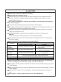
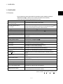
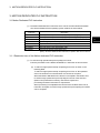
Store and use the unit in the following environmental conditions.
Environment
Ambient
temperature
Ambient humidity
Storage
temperature
Atmosphere
Altitude
Vibration
Conditions
Motion controller/Servo amplifier
According to each instruction manual.
According to each instruction manual.
According to each instruction manual.
Servomotor
0°C to +40°C (With no freezing)
(32°F to +104°F)
80% RH or less
(With no dew condensation)
-20°C to +65°C
(-4°F to +149°F)
Indoors (where not subject to direct sunlight).
No corrosive gases, flammable gases, oil mist or dust must exist
1000m (3280.84ft.) or less above sea level
According to each instruction manual
When coupling with the synchronization encoder or servomotor shaft end, do not apply impact
such as by hitting with a hammer. Doing so may lead to detector damage.
Do not apply a load larger than the tolerable load onto the servomotor shaft. Doing so may lead
to shaft breakage.
When not using the module for a long time, disconnect the power line from the Motion controller
or servo amplifier.
Place the Motion controller and servo amplifier in static electricity preventing vinyl bags and
store.
When storing for a long time, please contact with our sales representative.
A-6
(4) Wiring
!
CAUTION
Correctly and securely wire the wires. Reconfirm the connections for mistakes and the terminal
screws for tightness after wiring. Failing to do so may lead to run away of the
servomotor.
After wiring, install the protective covers such as the terminal covers to the original positions.
Do not install a phase advancing capacitor, surge absorber or radio noise filter (option FR-BIF)
on the output side of the servo amplifier.
Correctly connect the output side (terminals U, V, W). Incorrect connections will lead the
servomotor to operate abnormally.
Do not connect a commercial power supply to the servomotor, as this may lead to trouble.
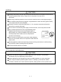
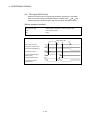
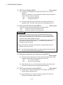
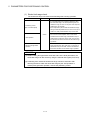
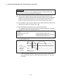
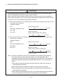
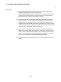
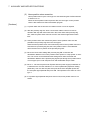
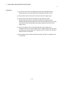
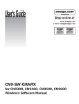
Do not mistake the direction of the surge absorbing diode
installed on the DC relay for the control signal output of
brake signals, etc. Incorrect installation may lead to signals
not being output when trouble occurs or the protective
functions not functioning.
Do not connect or disconnect the connection cables between
each unit, the encoder cable or PLC expansion cable while the
power is ON.
Servo amplifier
VIN
(24VDC)
Control output
signal
RA
Securely tighten the cable connector fixing screws and fixing mechanisms. Insufficient fixing
may lead to the cables combing off during operation.
Do not bundle the power line or cables.
(5) Trial operation and adjustment
!
CAUTION
Confirm and adjust the program and each parameter before operation. Unpredictable
movements may occur depending on the machine.
Extreme adjustments and changes may lead to unstable operation, so never make them.
When using the absolute position system function, on starting up, and when the Motion
controller or absolute value motor has been replaced, always perform a home position return.
A-7
(6) Usge methods
!
CAUTION
Immediately turn OFF the power if smoke, abnormal sounds or odors are emitted from the
Motion controller, servo amplifier or servomotor.
Always execute a test operation before starting actual operations after the program or
parameters have been changed or after maintenance and inspection.
The units must be disassembled and repaired by a qualified technician.
Do not make any modifications to the unit.
Keep the effect or electromagnetic obstacles to a minimum by installing a noise filter or by using
wire shields, etc. Electromagnetic obstacles may affect the electronic devices used near the
Motion controller or servo amplifier.
When using the CE Mark-compliant equipment, refer to the "EMC Installation Guidelines"
(data number IB(NA)-67339) for the Motion controllers and refer to the corresponding EMC
guideline information for the servo amplifiers, inverters and other equipment.
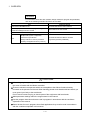
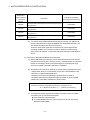
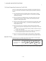
Use the units with the following conditions.
Item
Conditions
Q61P-A1
100 to 120VAC
Q61P-A2
+10%
-15%
200 to 240VAC
Q62P
+10%
-15%
Q63P
100 to 240VAC
+10%
-15%
24VDC
Q64P
+30%
-35%
100 to 120VAC
200 to 240VAC
Input power
(85 to 132VAC)
(170 to 264VAC)
(85 to 264VAC)
Input frequency
50/60Hz ±5%
Tolerable
momentary
power failure
20ms or less
(15.6 to 31.2VDC)
+10%
-15%
+10%
-15%
(85 to 132VAC/
170 to 264VAC)
(7) Corrective actions for errors
!
CAUTION
If an error occurs in the self diagnosis of the Motion controller or servo amplifier, confirm the
check details according to the instruction manual, and restore the operation.
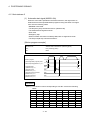
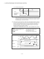
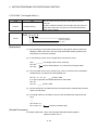
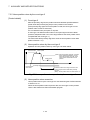
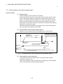
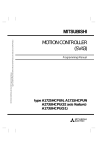
If a dangerous state is predicted in case of a power failure or product failure, use a servomotor
with electromagnetic brakes or install a brake mechanism externally.
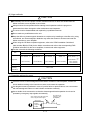
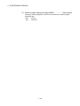
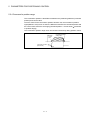
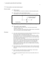
Use a double circuit construction so that the electromagnetic brake operation circuit can be
operated by emergency stop signals set externally.
Shut off with servo ON signal OFF,
alarm, magnetic brake signal.
Servomotor
RA1
Electromagnetic
brakes
Shut off with the
emergency stop
signal(EMG).
EMG
24VDC
A-8
/
`
!
CAUTION
If an error occurs, remove the cause, secure the safety and then resume operation after alarm
release.
The unit may suddenly resume operation after a power failure is restored, so do not go near the
machine. (Design the machine so that personal safety can be ensured even if the machine
restarts suddenly.)
(8) Maintenance, inspection and part replacement
!
CAUTION
Perform the daily and periodic inspections according to the instruction manual.
Perform maintenance and inspection after backing up the program and parameters for the
Motion controller and servo amplifier.
Do not place fingers or hands in the clearance when opening or closing any opening.
Periodically replace consumable parts such as batteries according to the instruction manual.
Do not touch the lead sections such as ICs or the connector contacts.
Do not place the Motion controller or servo amplifier on metal that may cause a power leakage
or wood, plastic or vinyl that may cause static electricity buildup.
Do not perform a megger test (insulation resistance measurement) during inspection.
When replacing the Motion controller or servo amplifier, always set the new module settings
correctly.
When the Motion controller or absolute value motor has been replaced, carry out a home
position return operation using one of the following methods, otherwise position displacement
could occur.
1) After writing the servo data to the Motion controller using programming software, switch on
the power again, then perform a home position return operation.
2) Using the backup function of the programming software, load the data backed up before
replacement.
After maintenance and inspections are completed, confirm that the position detection of the
absolute position detector function is correct.
Do not short circuit, charge, overheat, incinerate or disassemble the batteries.
The electrolytic capacitor will generate gas during a fault, so do not place your face near the
Motion controller or servo amplifier.
The electrolytic capacitor and fan will deteriorate. Periodically replace these to prevent
secondary damage from faults. Replacements can be made by our sales representative.
A-9
(9) About processing of waste
When you discard Motion controller, servo amplifier, a battery (primary battery) and other option articles,
please follow the law of each country (area).
!
CAUTION
This product is not designed or manufactured to be used in equipment or systems in situations
that can affect or endanger human life.
When considering this product for operation in special applications such as machinery or
systems used in passenger transportation, medical, aerospace, atomic power, electric power, or
submarine repeating applications, please contact your nearest Mitsubishi sales representative.
Although this product was manufactured under conditions of strict quality control, you are
strongly advised to install safety devices to forestall serious accidents when it is used in facilities
where a breakdown in the product is likely to cause a serious accident.
(10) General cautions
!
CAUTION
All drawings provided in the instruction manual show the state with the covers and safety
partitions removed to explain detailed sections. When operating the product, always return the
covers and partitions to the designated positions, and operate according to the instruction
manual.
A - 10
REVISIONS
The manual number is given on the bottom left of the back cover.
Print Date
Feb., 2006
Manual Number
IB(NA)-0300115-A First edition
Revision
Japanese Manual Number IB(NA)-0300095
This manual confers no industrial property rights or any rights of any other kind, nor does it confer any patent
licenses. Mitsubishi Electric Corporation cannot be held responsible for any problems involving industrial property
rights which may occur as a result of using the contents noted in this manual.
© 2006 MITSUBISHI ELECTRIC CORPORATION
A - 11
INTRODUCTION
Thank you for choosing the Q173HCPU/Q172HCPU Motion Controller.
Please read this manual carefully so that equipment is used to its optimum.
CONTENTS
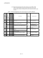
Safety Precautions .........................................................................................................................................A- 1
Revisions ........................................................................................................................................................A-11
Contents .........................................................................................................................................................A-12
About Manuals ...............................................................................................................................................A-17
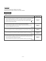
1. OVERVIEW
1- 1 to 1- 6
1.1 Overview................................................................................................................................................... 11.2 Features ................................................................................................................................................... 11.2.1 Performance specifications............................................................................................................... 11.2.2 Differences between Q173HCPU/Q172HCPU and Q173CPU(N)/Q172CPU(N)......................... 12. POSITIONING CONTROL BY THE MOTION CPU
1
3
3
6
2- 1 to 2-10
2.1 Positioning Control by the Motion CPU................................................................................................... 2- 1
3. MOTION DEDICATED PLC INSTRUCTION
3- 1 to 3-44
3.1 Motion Dedicated PLC Instruction........................................................................................................... 3- 1
3.1.1 Restriction item of the Motion dedicated PLC instruction ................................................................ 3- 1
3.2 Motion program (Control program) Start Request from The PLC CPU to The Motion CPU:
S(P).SFCS (PLC instruction: S(P).SFCS )............................................................................................ 3- 8
3.3 Motion Program (Axis designation program) Start Request from The PLC CPU to The Motion CPU:
S(P).SVST (PLC instruction: S(P).SVST ) ............................................................................................ 3-13
3.4 Home position return instruction from The PLC CPU to The Motion CPU:
S(P).CHGA (PLC instruction: S(P).CHGA )........................................................................................... 3-19
3.5 Speed Change Instruction from The PLC CPU to The Motion CPU:
S(P).CHGV (PLC instruction: S(P).CHGV )........................................................................................... 3-24
3.6 Torque Limit Value Change Request Instruction from The PLC CPU to The Motion CPU:
S(P).CHGT (PLC instruction: S(P) .CHGT ).......................................................................................... 3-32
3.7 Write from The PLC CPU to The Motion CPU: S(P).DDWR (PLC instruction: S(P).DDWR ) .............. 3-36
3.8 Read from The Devices of The Motion CPU: S(P).DDRD (PLC instruction: S(P).DDRD ) ................. 3-40
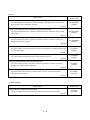
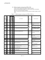
4. POSITIONING SIGNALS
4- 1 to 4-88
4.1 Internal Relays ......................................................................................................................................... 4- 2
4.1.1 Axis statuses ..................................................................................................................................... 4-13
4.1.2 Axis command signals ...................................................................................................................... 4-26
4.1.3 Axis statuses 2 .................................................................................................................................. 4-33
4.1.4 Axis command signals 2 ................................................................................................................... 4-36
4.1.5 Common devices .............................................................................................................................. 4-45
4.2 Data Registers.......................................................................................................................................... 4-56
A - 12
4.2.1 Axis monitor devices ......................................................................................................................... 4-64
4.2.2 Control change registers................................................................................................................... 4-67
4.2.3 Axis monitor devices 2 ...................................................................................................................... 4-68
4.2.4 Control program monitor devices ..................................................................................................... 4-72
4.2.5 Control change registers 2................................................................................................................ 4-74
4.2.6 Tool length offset data setting registers............................................................................................ 4-75
4.2.7 Common devices .............................................................................................................................. 4-76
4.3 Motion Registers (#)................................................................................................................................. 4-79
4.4 Special Relays (SP.M) ............................................................................................................................. 4-80
4.5 Special Registers (SP.D) ......................................................................................................................... 4-83
5. PARAMETERS FOR POSITIONING CONTROL
5- 1 to 5-20
5.1 System Settings ....................................................................................................................................... 5- 1
5.2 Fixed Parameters..................................................................................................................................... 5- 2
5.2.1 Number of pulses/travel value per rotation....................................................................................... 5- 3
5.2.2 Backlash compensation amount....................................................................................................... 5- 5
5.2.3 Upper/lower stroke limit value........................................................................................................... 5- 5
5.2.4 Command in-position range.............................................................................................................. 5- 7
5.2.5 High-speed feed rate setting............................................................................................................. 5- 8
5.2.6 Speed control 10 multiplier setting for degree axis ........................................................................ 5- 9
5.3 Parameter Block....................................................................................................................................... 5-13
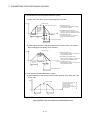
5.3.1 Relationships between the speed limit value, acceleration time, deceleration time and rapid
stop deceleration time ................................................................................................................... 5-16
5.3.2 S-curve ratio ...................................................................................................................................... 5-18
5.3.3 Allowable error range for circular interpolation................................................................................. 5-19
5.4 Work Coordinate Data ............................................................................................................................. 5-20
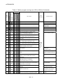
6. MOTION PROGRAMS FOR POSITIONING CONTROL
6- 1 to 6-186
6.1 Motion Program Composition .................................................................................................................. 6- 1
6.2 Type of The Motion Program................................................................................................................... 6- 4
6.3 G-code List ............................................................................................................................................... 6- 5
6.4 M-code List ............................................................................................................................................... 6- 7
6.5 Control Instruction List ............................................................................................................................. 6- 8
6.6 Start/End Method ..................................................................................................................................... 6-10
6.7 Number of Maximum Nesting for Program Call and Multi Startable Program....................................... 6-12
6.8 Motion parameter ..................................................................................................................................... 6-13
6.9 Caution at The Axis Designation Program Creation............................................................................... 6-14
6.10 Instruction Symbols/Characters List...................................................................................................... 6-19
6.11 Setting Method for Command Data....................................................................................................... 6-23
6.11.1 Direct setting (numerical value) ...................................................................................................... 6-23
6.11.2 Indirect setting ................................................................................................................................. 6-24
6.11.3 Operational data.............................................................................................................................. 6-31
6.11.4 Setting range of instruction symbols list ......................................................................................... 6-41
6.11.5 Positioning control unit for 1 axis .................................................................................................... 6-43
6.11.6 Control units for interpolation control.............................................................................................. 6-44
6.11.7 Control in the control unit "degree"................................................................................................. 6-46
6.12 About Coordinate Systems.................................................................................................................... 6-48
A - 13
6.13 G-code.................................................................................................................................................... 6-49
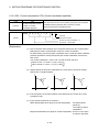
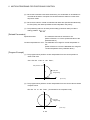
6.13.1 G00 Point-to-point positioning at the high-speed feed rate .......................................................... 6-52
6.13.2 G01 Constant-speed positioning at the speed specified in F ....................................................... 6-54
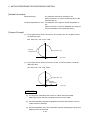
6.13.3 G02 Circular interpolation CW (Central coordinates-specified) .................................................. 6-56
6.13.4 G03 Circular interpolation CCW (Central coordinates-specified)................................................. 6-59
6.13.5 G02 Circular interpolation CW (Radius-specified) ........................................................................ 6-62
6.13.6 G03 Circular interpolation CCW (Radius-specified) ..................................................................... 6-64
6.13.7 G04 Dwell....................................................................................................................................... 6-66
6.13.8 G09 Exact stop check .................................................................................................................... 6-68
6.13.9 G12 Helical interpolation CW (Helical central coordinates-specified).......................................... 6-70
6.13.10 G13 Helical interpolation CCW (Helical central coordinates-specified) ..................................... 6-73
6.13.11 G12 Helical interpolation CW (Helical radius-specified) ............................................................. 6-75
6.13.12 G13 Helical interpolation CCW (Helical radius-specified) .......................................................... 6-77
6.13.13 G23 Cancel, cancel start invalid .................................................................................................. 6-79
6.13.14 G24 Cancel, cancel start.............................................................................................................. 6-80
6.13.15 G25 High-speed oscillation.......................................................................................................... 6-83
6.13.16 G26 High-speed oscillation stop.................................................................................................. 6-85
6.13.17 G28 Home position return............................................................................................................ 6-86
6.13.18 G30 Second home position return............................................................................................... 6-88
6.13.19 G32 Skip....................................................................................................................................... 6-90
6.13.20 G43 Tool length offset (+) ............................................................................................................ 6-94
6.13.21 G44 Tool length offset (-) ............................................................................................................. 6-96
6.13.22 G49 Tool length offset cancel...................................................................................................... 6-98
6.13.23 G53 Mechanical coordinate system selection............................................................................. 6-99
6.13.24 G54 to G59 Work coordinate system selection ........................................................................ 6-101
6.13.25 G61 Exact stop check mode...................................................................................................... 6-104
6.13.26 G64 Cutting mode ...................................................................................................................... 6-106
6.13.27 G90 Absolute value command .................................................................................................. 6-108
6.13.28 G91 Incremental value command ............................................................................................. 6-110
6.13.29 G92 Coordinates system setting ............................................................................................... 6-112
6.13.30 G98, G99 Preread disable/enable............................................................................................. 6-114
6.13.31 G100, G101 Time-fixed acceleration/deceleration, acceleration-fixed acceleration/deceleration
switching command..................................................................................................................... 6-116
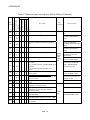
6.14 M-Code................................................................................................................................................. 6-120
6.15 Special M-Code.................................................................................................................................... 6-121
6.15.1 M00 Program stop ....................................................................................................................... 6-122
6.15.2 M01 Optional program stop ........................................................................................................ 6-123
6.15.3 M02 Program end ........................................................................................................................ 6-124
6.15.4 M30 Program end ........................................................................................................................ 6-125
6.15.5 M98, M99 Subprogram call, subprogram end ........................................................................... 6-126
6.15.6 M100 Preread disable ................................................................................................................. 6-128
6.16 Miscellaneous....................................................................................................................................... 6-129
6.16.1 Program control function (IF, GOTO statement) ........................................................................ 6-130
6.16.2 Program control function (IF, THEN, ELSE, END statements) ................................................. 6-132
6.16.3 Program control function (WHILE, DO, END statements)......................................................... 6-134
6.16.4 Four fundamental operators, assignment operator (+, -, *, /, MOD, =)..................................... 6-136
6.16.5 Trigonometric functions (SIN, COS, TAN, ASIN, ACOS, ATAN) .............................................. 6-138
6.16.6 Real number to BIN value conversion (INT)............................................................................... 6-139
6.16.7 BIN value to real number conversion (FLT)................................................................................ 6-140
A - 14
6.16.8 32-bit real number and 64-bit real number data conversion (DFLT, SFLT) ............................... 6-141
6.16.9 Functions (SQRT, ABS, BIN, BCD, LN, EXP, RND, FIX, FUP)................................................ 6-142
6.16.10 Logical operators (AND, OR, XOR, NOT, <<, >>) ................................................................... 6-143
6.16.11 Move block wait functions (WAITON, WAITOFF)..................................................................... 6-145
6.16.12 Block wait functions (EXEON, EXEOFF) .................................................................................. 6-147
6.16.13 Bit set and reset for word devices (BSET, BRST)..................................................................... 6-150
6.16.14 Parameter block change (PB) ................................................................................................... 6-151
6.16.15 Torque limit value change (TL).................................................................................................. 6-153
6.16.16 Home position return (CHGA) .................................................................................................... 6-155
6.16.17 Speed change (CHGV)............................................................................................................... 6-156
6.16.18 Torque limit value change (CHGT)............................................................................................. 6-157
6.16.19 Bit device set, reset functions (SET, RST) ............................................................................... 6-158
6.16.20 Bit device operation on condition (IF, THEN, SET/RST/OUT) ................................................. 6-159
6.16.21 Program start (CALL).................................................................................................................. 6-161
6.16.22 Program call 1 (GOSUB) ............................................................................................................ 6-163
6.16.23 Program call 2 (GOSUBE) ......................................................................................................... 6-164
6.16.24 Control program end (CLEAR) ................................................................................................... 6-167
6.16.25 Time to wait (TIME)..................................................................................................................... 6-169
6.16.26 Block transfers (BMOV : 16-bit unit) .......................................................................................... 6-170
6.16.27 Block transfer (BDMOV : 32-bit unit)......................................................................................... 6-172
6.16.28 Identical data block transfers (FMOV)........................................................................................ 6-174
6.16.29 Write device data to shared CPU memory (MULTW) ............................................................... 6-176
6.16.30 Read device data from shared CPU memory of the other CPU (MULTR)............................... 6-178
6.16.31 Write words data to intelligent function module/special function module (TO)......................... 6-180
6.16.32 Read words data from intelligent function module/special function module (FROM) .............. 6-182
6.16.33 Conditional branch using bit device (ON, OFF) ....................................................................... 6-184
7. AUXILIARY AND APPLIED FUNCTIONS
7- 1 to 7-80
7.1 Backlash Compensation Function........................................................................................................... 7- 1
7.2 Torque Limit Function .............................................................................................................................. 7- 3
7.3 Home Position Return.............................................................................................................................. 7- 5
7.3.1 Home position return data................................................................................................................. 7- 6
7.3.2 Home position return by the proximity dog type 1............................................................................ 7-16
7.3.3 Home position return by the proximity dog type 2............................................................................ 7-19
7.3.4 Home position return by the count type 1......................................................................................... 7-21
7.3.5 Home position return by the count type 2......................................................................................... 7-23
7.3.6 Home position return by the count type 3......................................................................................... 7-25
7.3.7 Home position return by the data set type 1 .................................................................................... 7-27
7.3.8 Home position return by the data set type 2 .................................................................................... 7-28
7.3.9 Home position return by the dog cradle type ................................................................................... 7-29
7.3.10 Home position return by the stopper type 1 ................................................................................... 7-33
7.3.11 Home position return by the stopper type 2 ................................................................................... 7-35
7.3.12 Home position return by the limit switch combined type................................................................ 7-37
7.3.13 Home position return retry function ................................................................................................ 7-39
7.3.14 Home position shift function............................................................................................................ 7-43
7.3.15 Condition selection of home position set........................................................................................ 7-47
7.3.16 Execution of home position return................................................................................................. 7-48
7.4 Speed Change (CHGV instruction) ......................................................................................................... 7-49
A - 15
7.5 JOG Operation ......................................................................................................................................... 7-53
7.5.1 JOG operation data........................................................................................................................... 7-53
7.5.2 Individual start ................................................................................................................................... 7-54
7.5.3 Simultaneous start............................................................................................................................. 7-59
7.6 Manual Pulse Generator Operation......................................................................................................... 7-62
7.7 Override Ratio Setting Function .............................................................................................................. 7-68
7.8 FIN signal wait function............................................................................................................................ 7-70
7.9 Single Block Operation ............................................................................................................................ 7-74
7.10 Control Program Stop Function from The PLC CPU............................................................................ 7-79
8. USER FILES
8- 1 to 8- 2
8.1 Projects..................................................................................................................................................... 8- 1
8.2 User File List............................................................................................................................................. 8- 2
APPENDICES
APP- 1 to APP-67
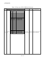
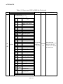
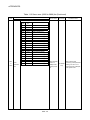
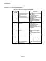
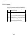
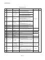
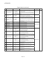
APPENDIX 1 Error Codes Stored Using The Motion CPU ....................................................................APP- 1
APPENDIX 1.1 Motion program setting errors (Stored in D9190).......................................................APP- 3
APPENDIX 1.2 Minor errors .................................................................................................................APP- 4
APPENDIX 1.3 Major errors .................................................................................................................APP-20
APPENDIX 1.4 Servo errors.................................................................................................................APP-24
APPENDIX 1.5 PC link communication errors .....................................................................................APP-41
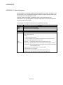
APPENDIX 2 Motion dedicated signal.....................................................................................................APP-42
APPENDIX 2.1 Internal relay (M) .........................................................................................................APP-42
APPENDIX 2.2 Data registers (D) ........................................................................................................APP-52
APPENDIX 2.3 Motion Registers (#) ....................................................................................................APP-59
APPENDIX 2.4 Special Relays .............................................................................................................APP-60
APPENDIX 2.5 Special Registers.........................................................................................................APP-63
APPENDIX 3 Processing Times of the Motion CPU ...............................................................................APP-67
A - 16
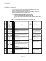
About Manuals
The following manuals are related to this product.
Referring to this list, please request the necessary manuals.
Related Manuals
(1) Motion controller
Manual Number
(Model Code)
Manual Name
Q173HCPU/Q172HCPU Motion controller User's Manual
This manual explains specifications of the Motion CPU modules, Q172LX Servo external signal interface
module, Q172EX Serial absolute synchronous encoder interface module, Q173PX Manual pulse
generator interface module, Teaching units, Power supply modules, Servo amplifiers, SSCNET
cables,
IB-0300110
(1XB910)
synchronous encoder cables and others.
(Optional)
Q173HCPU/Q172HCPU Motion controller Programming Manual (COMMON)
This manual explains the Multiple CPU system configuration, performance specifications, common
parameters, auxiliary/applied functions and others.
IB-0300111
(1XB911)
(Optional)
Q173HCPU/Q172HCPU Motion controller (SV13/SV22) Programming Manual (Motion SFC)
This manual explains the functions, programming, debugging, error codes and others of the Motion SFC.
IB-0300112
(1XB912)
(Optional)
Q173HCPU/Q172HCPU Motion controller (SV13/SV22) Programming Manual (REAL MODE)
This manual explains the servo parameters, positioning instructions, device list, error list and others.
IB-0300113
(1XB913)
(Optional)
Q173HCPU/Q172HCPU Motion controller (SV22) Programming Manual (VIRTUAL MODE)
This manual describes the dedicated instructions use to the synchronous control by virtual main shaft,
mechanical system program create mechanical module.
This manual explains the servo parameters, positioning instructions, device list, error list and others.
(Optional)
A - 17
IB-0300114
(1XB914)
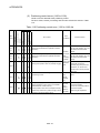
(2) PLC
Manual Number
(Model Code)
Manual Name
QCPU User's Manual (Hardware Design, Maintenance and Inspection)
This manual explains the specifications of the QCPU modules, power supply modules, base modules,
extension cables, memory card battery and others.
SH-080483ENG
(13JR73)
(Optional)
QCPU User's Manual (Function Explanation, Program Fundamentals)
This manual explains the functions, programming methods and devices and others to create programs
with the QCPU.
SH-080484ENG
(13JR74)
(Optional)
QCPU User's Manual (Multiple CPU System)
This manual explains the functions, programming methods and cautions and others to construct the
Multiple CPU system with the QCPU.
SH-080485ENG
(13JR75)
(Optional)
QCPU (Q Mode)/QnACPU Programming Manual (Common Instructions)
This manual explains how to use the sequence instructions, basic instructions, application instructions and
micro computer program.
SH-080039
(13JF58)
(Optional)
QCPU (Q Mode)/QnACPU Programming Manual (PID Control Instructions)
SH-080040
(13JF59)
This manual explains the dedicated instructions used to exercise PID control.
(Optional)
QCPU (Q Mode)/QnACPU Programming Manual (SFC)
This manual explains the system configuration, performance specifications, functions, programming,
debugging, error codes and others of MELSAP3.
SH-080041
(13JF60)
(Optional)
I/O Module Type Building Block User's Manual
SH-080042
(13JL99)
This manual explains the specifications of the I/O modules, connector, connector/terminal block
conversion modules and others.
(Optional)
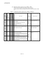
(3) Servo amplifier
Manual Number
(Model Code)
Manual Name
MR-J3-B Servo amplifier Instruction Manual
SH-030051
(1CW202)
This manual explains the I/O signals, parts names, parameters, start-up procedure and others.
(Optional)
A - 18
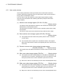
1 OVERVIEW
1. OVERVIEW
1
1.1 Overview
This programming manual describes the operating system software packages
"SW5RN-SV43Q " for Motion CPU module (Q173HCPU/Q172HCPU).
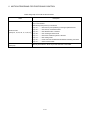
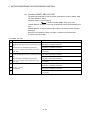
In this manual, the following abbreviations are used.
Generic term/Abbreviation
Description
Q173HCPU/Q172HCPU or
Motion CPU (module)
Q173HCPU/Q172HCPU Motion CPU module
Q172LX/Q172EX/Q173PX or
Motion module
Q172LX Servo external signals interface module/
(Note-1)
Q172EX-S2/S3 Serial absolute synchronous encoder interface module
/
Q173PX(-S1) Manual pulse generator interface module
MR-J3- B
Servo amplifier model MR-J3- B
AMP or Servo amplifier
General name for "servo amplifier model MR-J3- B"
QCPU, PLC CPU or PLC CPU module
Qn(H)CPU
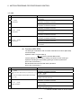
Multiple CPU system or Motion system
Abbreviation for "Multiple PLC system of the Q series"
CPUn
Abbreviation for "CPU No.n (n= 1 to 4) of the CPU module for the Multiple
CPU system"
Programming software package
General name for "MT Developer" and "GX Developer"
Operating system software
General name for "SW RN-SV Q "
SV43
Operating system software for machine tool peripheral use: SW5RN-SV43Q
MT Developer
Abbreviation for "MT Developer (Version 00M or later)"
(Integrated start-up support software package)
GX Developer
Abbreviation for "GX Developer (Version 6 or later)"
(GX Developer function software package)
Manual pulse generator or MR-HDP01
Abbreviation for "Manual pulse generator (MR-HDP01)"
Serial absolute synchronous encoder
or Q170ENC
Abbreviation for "Serial absolute synchronous encoder (Q170ENC)"
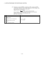
SSCNET
(Note-2)
High speed synchronous network between Motion controller and servo
amplifier
SSCNET
High speed serial communication between Motion controller and servo
amplifier
Absolute position system
General name for "system using the servomotor and servo amplifier for
absolute position"
Battery holder unit
Battery holder unit (Q170HBATC)
External battery
General name for "Q170HBATC" and "Q6BAT"
A 0BD-PCF
A10BD-PCF/A30BD-PCF SSC I/F board
SSC I/F communication cable
Abbreviation for "Cable for SSC I/F board/card"
Intelligent function module
Abbreviation for "MELSECNET/H module/Ethernet module/
CC-Link module/Serial communication module"
(Note-2)
(Note-1) : Q172EX can be used in SV22.
(Note-2) : SSCNET: Servo System Controller NETwork
1-1
1 OVERVIEW
REMARK
For information about the each module, design method for program and parameter,
refer to the following manuals relevant to each module.
Item
Reference Manual
Motion CPU module/Motion unit
Q173HCPU/Q172HCPU User’s Manual
PLC CPU, peripheral devices for PLC program design, I/O
modules and intelligent function module
Operation method for MT Developer
Manual relevant to each module
Help of each software
• Multiple CPU system configuration
SV43
• Performance specification
Q173HCPU/Q172HCPU Motion controller
• Design method for common parameter
Programming Manual (COMMON)
• Auxiliary and applied functions (common)
!
CAUTION
When designing the system, provide external protective and safety circuits to ensure safety in
the event of trouble with the Motion controller.
There are electronic components which are susceptible to the effects of static electricity
mounted on the printed circuit board. When handling printed circuit boards with bare hands you
must ground your body or the work bench.
Do not touch current-carrying or electric parts of the equipment with bare hands.
Make parameter settings within the ranges stated in this manual.
Use the program instructions that are used in programs in accordance with the conditions
stipulated in this manual.
Some devices for use in programs have fixed applications: they must be used in accordance
with the conditions stipulated in this manual.
1-2
1 OVERVIEW
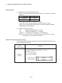
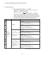
1.2 Features
The Motion CPU has the following features.
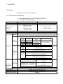
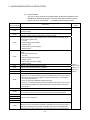
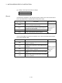
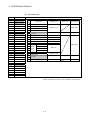
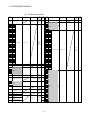
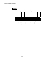
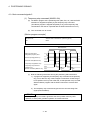
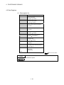
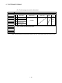
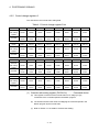
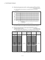
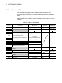
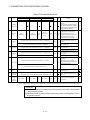
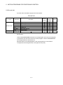
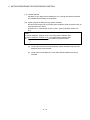
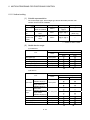
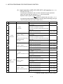
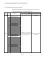
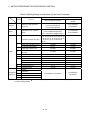
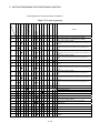
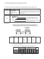
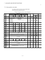
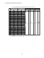
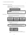
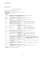
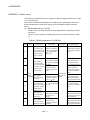
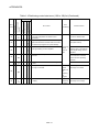
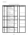
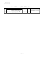
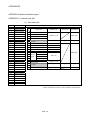
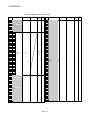
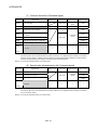
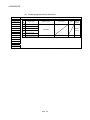
1.2.1 Performance specifications
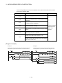
(1) Basic specifications of Q172HCPU/Q172HCPU
(a) Motion control specifications
Item
Number of control axes
Q173HCPU
Q172HCPU
Up to 32 axes
Up to 8 axes
0.88ms/ 1 to 5 axes
Operation cycle
1.77ms/ 6 to 14 axes
0.88ms/ 1 to 5 axes
(Default)
3.55ms/15 to 28 axes
1.77ms/ 6 to 8 axes
7.11ms/29 to 32 axes
Interpolation functions
Control modes
Linear interpolation (Up to 4 axes), Circular interpolation (2 axes), Helical interpolation (3 axes)
PTP (Point to Point) control, Constant speed positioning, High-speed oscillation control
Method
PTP : Select of absolute or incremental data method.
Constant-speed control : Both absolute and incremental data method can be used together.
Selectable for each axis
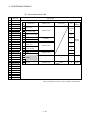
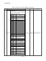
Control
Position
unit
command
mm
Address setting
Command unit
range
-4
-2147483648 to
-5
2147483647
10 mm
inch
10 inch
degree
-5
10 degree
Travel value setting range
0 to ±2147483647
0 to 35999999
Positioning
Control
Speed setting range
unit
Speed
mm
0.01 to 6000000.00 (mm/min)
command
inch
0.001 to 600000.000 (inch/min)
(Command
unit)
• Speed control 10 multiplier setting for degree axis is invalid
degree
0.001 to 2147483.647 (degree/min)
• Speed control 10 multiplier setting for degree axis is valid
0.01 to 21474836.47 (degree/min)
Automatic
Acceleration-fixed
Time-fixed acceleration/deceleration
acceleration/deceleration method
method
Acceleration/ trapezoidal
Acceleration time : 1 to 65535 ms
deceleration
Deceleration time : 1 to 65535 ms
control
S-curve
Compensation
Acceleration/deceleration time :
1 to 5000 ms
(Only constant speed control)
S-curve ratio : 0 to 100[%]
Backlash compensation, Electronic gear
Programming language
Dedicated instruction (EIA language)
Motion program capacity
248k bytes
1-3
(Note-1)
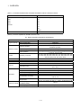
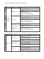
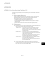
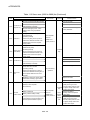
1 OVERVIEW
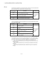
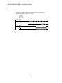
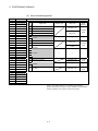
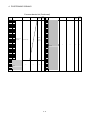
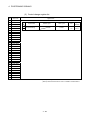
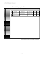
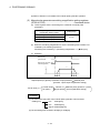
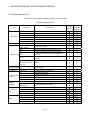
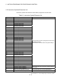
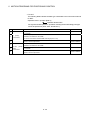
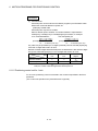
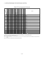
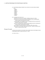
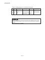
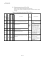
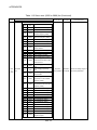
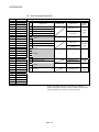
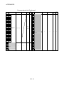
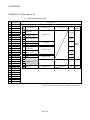
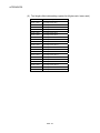
Motion control specifications (continued)
Item
Q173HCPU
Q172HCPU
Number of programs
Number of simultaneous
start programs
1024
Axis designation program : 32
Axis designation program : 8
Control program : 16
Control program : 16
Number of positioning
points
Approx. 10600 points
(Positioning data can be designated indirectly)
Number of I/O (X/Y) points
8192 points
Number of real I/O (PX/PY)
Total 256 points
points
Internal relays
Number of
(M)
Devices
Latch relays
(internal
(L)
motion
Link relays (B)
CPU only)
Annunciators
Total (M+L) : 8192 points
8192 points
2048 points
(F)
Programming tool
IBM PC/AT
Peripheral I/F
USB/SSCNET
Teaching operation
None
function
Home position return
function
Proximity dog type (2 types), Count type (3 types), Data set type (2 types), Dog cradle type,
Stopper type (2 types), Limit switch combined type
(Home position return re-try function provided, home position shift function provided)
JOG operation function
Provided
Manual pulse generator
Possible to connect 3 modules.
operation function
M-code function
Limit switch output function
M-code output function provided
M-code completion wait function provided
Number of output points 32 points
Watch data: Motion control data/Word device
Skip function
Provided
Override ratio setting
Override ratio setting : 0 to 100[%]
function
Absolute position system
Number of SSCNET
Made compatible by setting battery to servo amplifier.
(Possible to select the absolute data method or incremental method for each axis)
2 systems
1 system
Number of Motion related
Q172LX : 4 modules
Q172LX : 1 module
modules
Q173PX : 1 module
Q173PX : 1 module
systems
(Note-2)
1-4
1 OVERVIEW
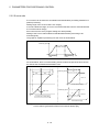
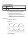
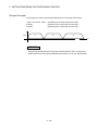
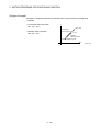
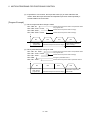
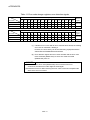
(Note-1) : Acceleration-fixed/time-fixed acceleration/deceleration method is switched as follows.
Acceleration-fixed acceleration/deceleration method
Time-fixed acceleration/deceleration method
G00 (Without M-code setting.)
G00 (With M-code setting.)
G28
G01
G30
G02
G53
G03
in G100
G12
G13
G32
in G101
All travel instructions in G101
—
(Note-2) : The servo amplifiers for SSCNET cannot be used.
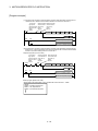
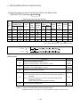
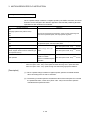
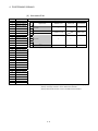
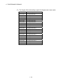
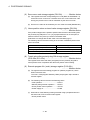
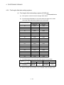
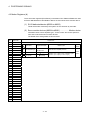
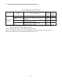
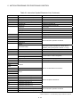
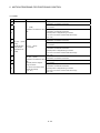
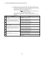
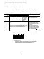
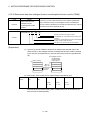
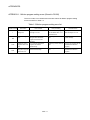
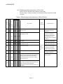
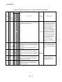
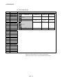
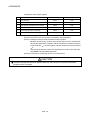
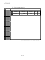
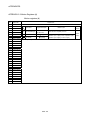
(b) Motion program performance specifications
Item
Program capacity
Total of program files
Number of programs
Arithmetic operation
Q173HCPU/Q172HCPU
248k bytes
Up to 1024 (No. 1 to 1024)
Unary operation, Additive operation, Multiplicative operation,
Remainder operation
Operation controls Comparison operation
G-codes
M-codes
Special M-codes
Variable
Trigonometric function
Functions
Instructions
Equal to, Not equal to
Logical shift operation, Logical negation, Logical AND,
Logical operation
Logical OR, Exclusive OR
G00, G01, G02, G03, G04, G09, G12, G13, G23, G24, G25, G26,
Positioning command
G28, G30, G32, G43, G44, G49, G53, G54, G55, G56, G61, G64,
G90, G91, G92, G98, G99, G100, G101
Output command to data register
M****
Program control command
M00, M01, M02, M30, M98, M99, M100
Device variable
X, Y, B, F, D, W, #
Numerical function
Start/end
Home position return
Speed/torque setting
Motion control
Jump/repetition processing
Data operation
SIN, COS, TAN, ASIN, ACOS, ATAN
ABS, SQR, BIN, LN, EXP, BCD, RND, FIX, FUP, INT, FLT,
DFLT, SFLT
CALL, CLEAR
CHGA
TL, CHGV, CHGT
WAITON, WAITOFF, EXEON, EXEOFF
CALL, GOSUB/GOSUBE, IF…GOTO, IF…THEN…ELSE…END,
WHILE…DO
BMOV, BDMOV, FMOV, BSET, BRST, SET, RST, MULTW,
MULTR, TO, FROM, ON, OFF, IF…THEN…SET/RST/OUT, PB
Number of program calls
Number of controls (GOSUB/GOSUBE)
Number of program calls (M98)
Up to 8
Up to 8
1-5
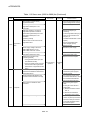
1 OVERVIEW
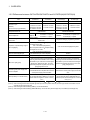
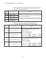
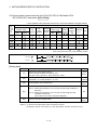
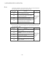
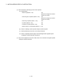
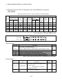
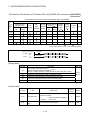
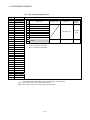
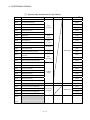
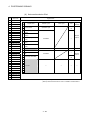
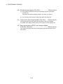
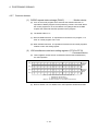
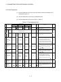
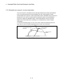
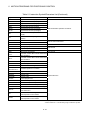
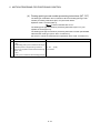
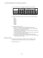
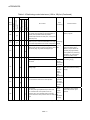
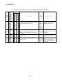
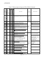
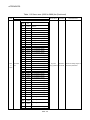
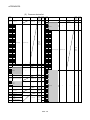
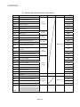
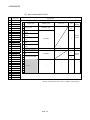
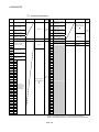
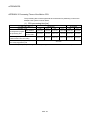
1.2.2 Differences between Q173HCPU/Q172HCPU and Q173CPU(N)/Q172CPU(N)
Item
Number of control axes
Operation cycle
(Default)
(It can be set up by parameters.)
Peripheral devices I/F
Q173HCPU
Q172HCPU
Q173CPU(N)
Q172CPU(N)
32 axes
8 axes
32 axes
8 axes
0.88ms/ 1 to 5 axes
1.77ms/ 6 to 14 axes
3.55ms/15 to 28 axes
7.11ms/29 to 32 axes
0.88ms/1 to 5 axes
1.77ms/6 to 8 axes
0.88ms/ 1 to 4 axes
1.77ms/ 5 to 12 axes
3.55ms/13 to 24 axes
7.11ms/25 to 32 axes
0.88ms/1 to 4 axes
1.77ms/5 to 8 axes
USB/SSCNET
Servo amplifier I/F
SSCNET
(Optical
communication)
Indirect setting of home position
return data
Indirect setting with word devices (D, W, #) of
Motion CPU.
Expansion of speed setting range in
the unit [degree]
Q173HCPU : 2 systems
Q172HCPU : 1 system
• When the speed control 10 multiplier setting
for degree axis is valid ;
0.01 to 21474836.47[degree/min]
• When the speed control 10 multiplier setting
for degree axis is invalid ;
0.001 to 2147483.647[degree/min]
USB/RS-232/SSCNET
SSCNET
Q173CPU(N) : 4 systems (Note-1)
Q172CPU(N) : 1 system
Only direct setting by programming software.
0.001 to 2147483.647[degree/min] fixed
Fetch of external signal input
Q172LX/General input of servo amplifier (Note-2)
Q172LX
Optional data monitor function
3 points/axis (Specified device D, W, #)
—
Minor error [303], [304]
When the speed change is executed after
When the speed change is executed after
positioning automatic decerelation start or during positioning automatic decerelation start or during
decerelation by the JOG start command signal
decerelation by the JOG start command signal
(M3202+20n, M3203+20n) OFF, a minor error
(M3202+20n, M3203+20n) OFF, since the
[303], [304] will occur.
speed change request is ignored, a minor error
[303], [304] will not occur.
Processing with power supply OFF
of servo amplifier
Servo OFF is executed for all servo amplifier
connected behind servo amplifier with which the
control power supply was turned OFF.
Servo OFF is executed for only servo amplifier
with which the control power supply was turned
OFF.
Internal rechargeable battery
(Set the external battery (Q6BAT) if continuous
power off time is longer for 1 month or more.)
Internal rechargeable battery
(Set the external battery (A6BAT/MR-BAT) if
continuous power off time is longer for 1 month or
more.) (Note-4)
Back-up battery for internal memory
(Note-3)
(Note-1) : Use the dividing unit (Q173DV) or dividing cable (Q173J2B CBL M/Q173HB CBL M).
(Note-2) : When selecting the each servo amplifier general input, the home position return by the count type cannot be executed. And, the
external stop input cannot be used.
(Note-3) : When adding the external battery (Q6BAT), use the Q170HBATC.
(Note-4) : When adding the external battery (A6BAT/MR-BAT), use the Q173DV (Q173CPU(N) use) or Q170BAT (Q172CPU(N) use).
1-6
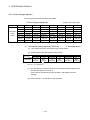
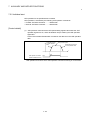
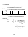
2 POSITIONING CONTROL BY THE MOTION CPU
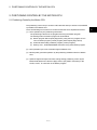
2. POSITIONING CONTROL BY THE MOTION CPU
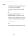
2.1 Positioning Control by the Motion CPU
The positioning control of up to 32 axes in Q173HCPU and up to 8 axes in Q172HCPU
is possible in the Motion CPU.
There are following four functions as controls toward the servo amplifier/servomotor.
(1) Servo operation by the positioning instructions.
The positioning instructions are programmed using the Motion program.
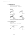
The starting method of Motion program is shown below.
(a) Motion program start request (S(P).SVST) using the PLC program of PLC
CPU or Motion program (control program) start request (S(P).SFCS)
(b) Automatic start setting of Motion program (control program)
(c) Start by CALL, GOSUB/GOSUBE instruction using other Motion program
(2) JOG operation by the axis command signal of Motion CPU.
(3) Manual pulse generator operation by the positioning dedicated device of Motion
CPU.
(4) Speed change and torque limit value change during positioning control by the
Motion dedicated PLC instruction (S(P).CHGV, S(P).CHGT instruction) or the
CHGV, CHGT, TL instruction in the Motion program.
2-1
2
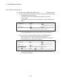
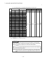
2 POSITIONING CONTROL BY THE MOTION CPU
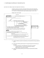
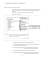
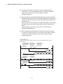
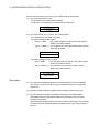
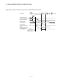
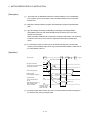
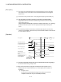
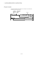
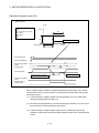
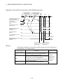
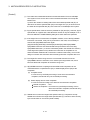
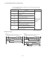
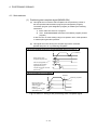
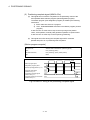
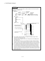
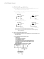
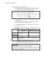
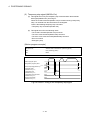
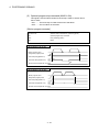
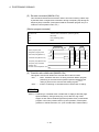
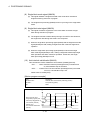
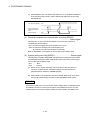
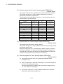
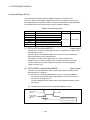
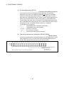
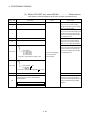
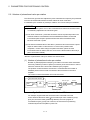
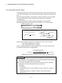
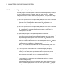
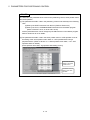
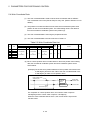
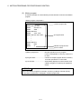
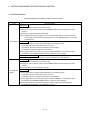
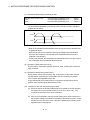
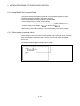
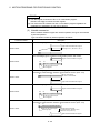
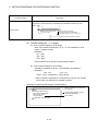
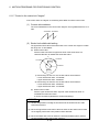
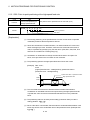
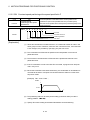
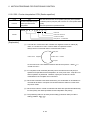
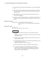
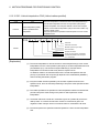
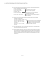
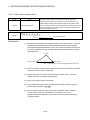
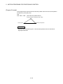
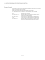
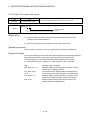
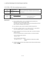
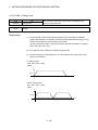
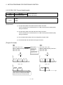
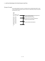
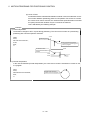
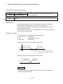
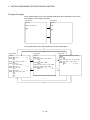
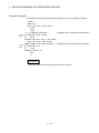
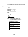
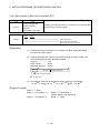
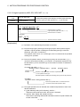
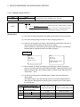
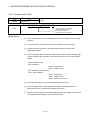
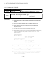
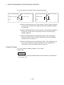
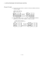
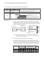
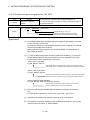
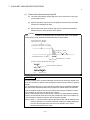
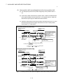
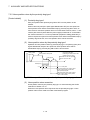
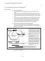
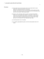
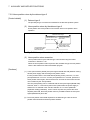
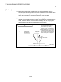
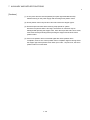
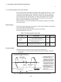
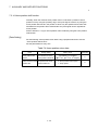
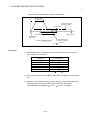
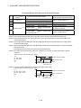
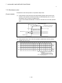
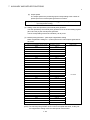
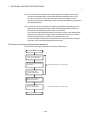
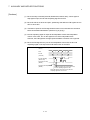
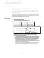
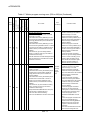
[Execution of the Motion program start (S(P).SVST instruction)]
Positioning control is executed by starting the Motion program (axis designation
program) specified with S(P).SVST instruction of the PLC CPU in the Motion CPU.
An overview of the starting method using the Motion program is shown below.
Multiple CPU control system
PLC CPU
PLC program . . . . . . . . . Create using a peripheral device (Note-1)
<Example> SP.SVST instruction
Positioning execute command
SP.SVST H3E3
"J1"
K15
M0
D0
Device which stores the
complete status
Complete device
Motion program No.15
Axis 1
(Start axis No.)
Target CPU
Start request of the
Motion program
1) The Motion program No. and start axis No. are set using the
S(P).SVST instruction in the PLC program.
2) When the S(P).SVST instruction is executed, the program of the
Motion program No. specified with the Motion CPU is executed.
Start request of the
Motion program
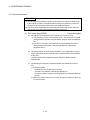
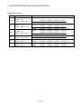
Point
In the above, it is explained the start of axis designation program.
There are following 2 types as the Motion program.
Control program : Only control instruction can be used, the travel instruction by G-code
can not be used.
It is started by the S(P).SFCS of PLC CPU, automatic start with parameter,
or CALL, GOSUB/GOSUBE instruction of other control program.
Axis designation program : The travel instruction by G-code and control instruction can be used.
It is started by the S(P).SVST instruction of PLC CPU or CALL,
GOSUB/GOSUBE instruction of control program.
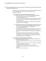
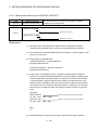
(1) Create the Motion programs and positioning control parameters using a peripheral
device.
(2) Perform the positioning start using the PLC program (S(P).SVST instruction) of
PLC CPU.
(a) Motion program No. is specified with the S(P).SVST instruction.
1) Motion program No. can be set either directly or indirectly.
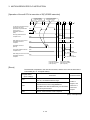
2) Start axis No. can be set only directly.
(3) Perform the specified positioning control using the specified with the Motion
program.
2-2
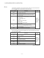
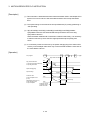
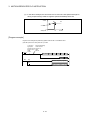
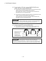
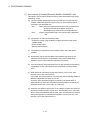
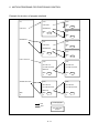
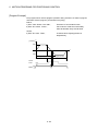
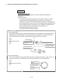
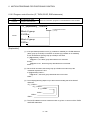
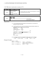
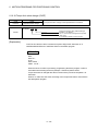
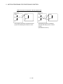
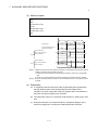
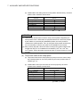
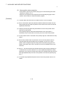
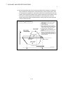
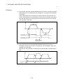
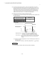
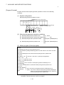
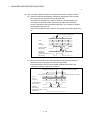
2 POSITIONING CONTROL BY THE MOTION CPU
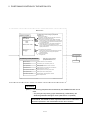
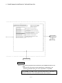
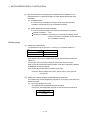
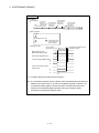
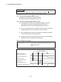
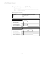
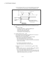
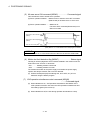
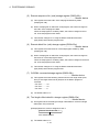
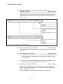
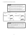
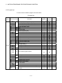
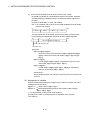
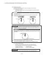
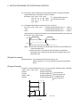
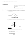
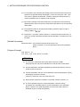
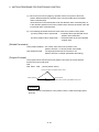
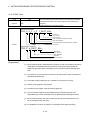
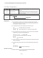
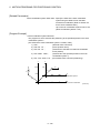
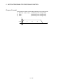
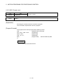
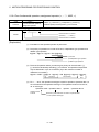
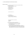
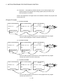
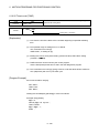
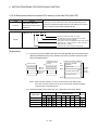
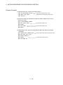
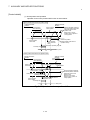
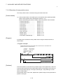
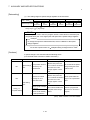
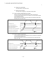
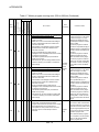
Motion CPU
Motion program
.....
Create and correct using a peripheral
device (Note-1)
Motion program No.15
(Program No. specified with the S(P).SVST instruction.)
All axes servo ON command turns on.
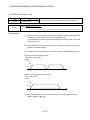
PTP positioning instruction by high-speed feed speed
Linear positioning of the specified axis is executed from
the current position to the specified coordinate position
by all axes fixed speed.
CP positioning instruction by the speed specified with F
Linear interpolation is executed from the current
position to the specified coordinate position by the feed
speed specified with F.
O0015;
SET #M2042
N10 G00 X100. Y100.;
X200.;
Y200.;
N20 G01 X25. F500.;
.
.
.
N70 G28 X0. Y0.;
N80 M02;
%
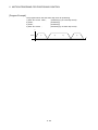
Home position return instruction
Home position return of the specified axis is executed
from the current position through the specified
coordinate position.
Program end instruction
Program ends.
Positioning control parameters
System settings
Servo amplifier
. . . . . Set and correct using a
peripheral device (Note-1)
Servomotor
System data such as axis allocations
Fixed parameters
Fixed data by the mechanical system, etc.
Servo parameters
Data by the specifications of the connected
servo amplifier
Parameters block
Data required for the acceleration, deceleration
of the positioning control, etc.
Home position return data
Data required for the home position return
JOG operation data
Data required for the JOG operation
Limit switch output data
ON/OFF pattern data required for the limit
switch output function
REMARK
(Note-1) : The following peripheral devices started by the SW6RN-GSV43P can be
used.
• The personal computer by which WindowsNT 4.0/Windows 98/
Windows 2000/Windows XP works. (IBM PC/AT compatible)
R
R
R
R
WindowsNT , Windows are either registered trademarks or trademarks of
Microsoft Corporation in the United States and/or other countries.
R
R
2-3
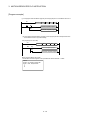
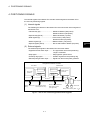
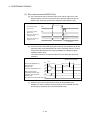
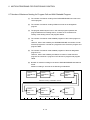
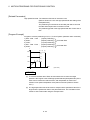
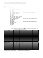
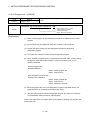
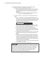
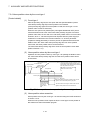
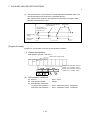
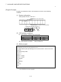
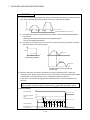
2 POSITIONING CONTROL BY THE MOTION CPU
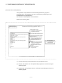
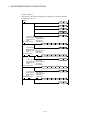
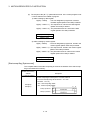
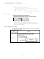
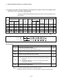
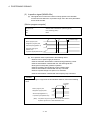
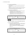
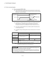
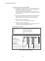
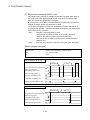
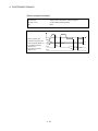
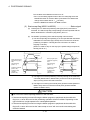
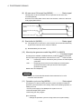
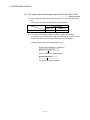
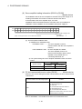
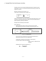
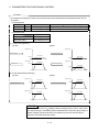
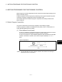
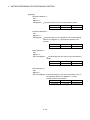
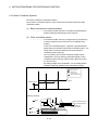
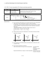
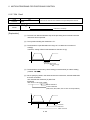
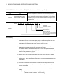
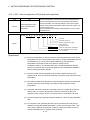
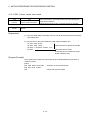
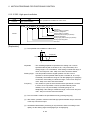
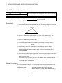
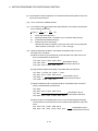
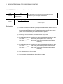
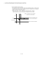
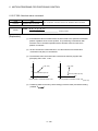
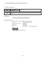
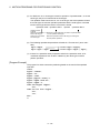
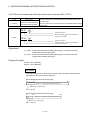
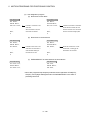
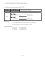
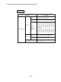
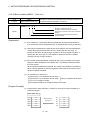
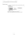
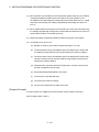
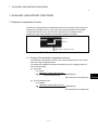
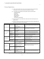
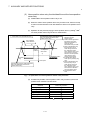
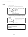
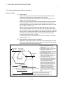
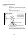
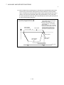
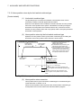
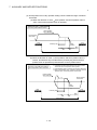
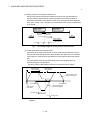
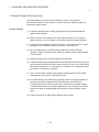
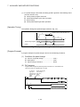
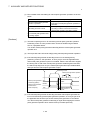
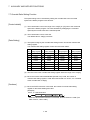
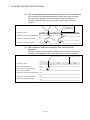
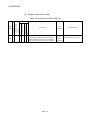
[Execution of the JOG operation]
JOG operation of specified axis is executed using the Motion program in
the Motion CPU. JOG operation can also be executed by controlling the JOG
dedicated device of specified axis.
An overview of JOG operation is shown below.
Motion CPU control system
Motion program
.....
Create and correct using a peripheral device (Note-1)
Motion program No.100
(Program No. specified with the
S(P).SFCS instruction.)
O 100;
S ET #M 2042;
N 10 IF[[O N #M 2415] AN D [O N #M 2435]] G O TO 20;
G O TO 10;
N 20 #D 640 = 100000;
#D 642L = 100000;
IF [[O N #X003] AN D [O FF #M 3203]] TH EN 1;
S ET #M 3202;
E LSE 1;
R ST #M 3202;
E ND 1;
IF [[O N #X004] AN D [O FF #M 3202]] TH EN 2;
S ET #M 3203;
E LSE 2;
R ST #M 3203;
E ND 2;
.
.
.
N 80 M 02;
%
All axes servo ON command turns on.
Transfer the JOG operation speed to
D640L and D642L.
Program control function instruction
The flow of execute program is
controlled by conditions.
1 axis forward rotation command
SET/RST
Program control function instruction
The flow of execute program is
controlled by conditions.
1 axis reverse rotation command
SET/RST
Program end instruction
Program ends.
JOG operation by
the JOG dedicated
device control
(1) Set the positioning control parameters using a peripheral device.
(2) Set the JOG speed to the JOG speed setting register for each axis using the
Motion program.
(3) Perform the JOG operation while the JOG start command signal is ON in the
Motion program.
2-4
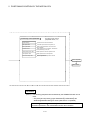
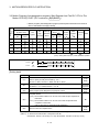
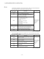
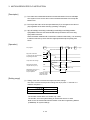
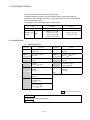
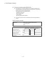
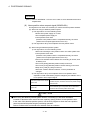
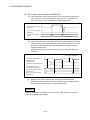
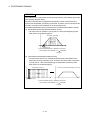
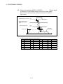
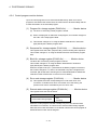
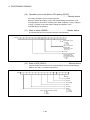
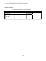
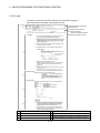
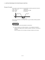
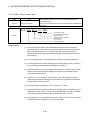
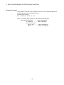
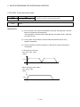
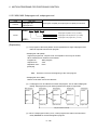
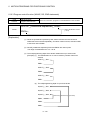
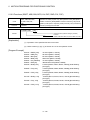
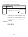
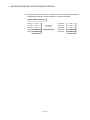
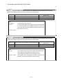
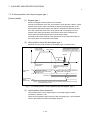
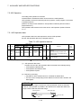
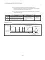
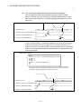
2 POSITIONING CONTROL BY THE MOTION CPU
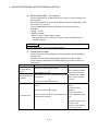
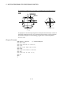
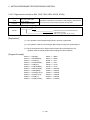
. . . . . Set and correct using a
Positioning control parameter
peripheral device (Note-1)
System settings
System data such as axis allocations
Fixed parameters
Fixed data by the mechanical system, etc.
Servo parameters
Parameter block
Data by the specifications of the connected
servo amplifier
Data required for the acceleration, deceleration
of the positioning control, etc.
Home position return data
Data required for the home position return
JOG operation data
Data required for the JOG operation
Limit switch output data
ON/OFF pattern data required for the limit
switch output function
Servo amplifier
Servomotor
REMARK
(Note-1) : The following peripheral devices started by the SW6RN-GSV43P can be
used.
• The personal computer by which WindowsNT 4.0/Windows 98/
Windows 2000/Windows XP works. (IBM PC/AT compatible)
R
R
R
R
WindowsNT , Windows are either registered trademarks or trademarks of
Microsoft Corporation in the United States and/or other countries.
R
R
2-5
2 POSITIONING CONTROL BY THE MOTION CPU
[Executing Manual Pulse Generator Operation]
When the positioning control is executed by the manual pulse generator connected to
the Q173PX, manual pulse generator operation must be enabled using the Motion
program.
An overview of manual pulse generator operation is shown below.
Motion CPU control system
Motion program
O100;
SET #M2042;
N10 IF[[ON #M2415] AND [ON #M2435]] GOTO 20;
GOTO 10;
N20 IF[ON #X000] GOTO 30;
GOTO 20;
N30 #D720 = 100;
#D721 = 100;
#D714L = 1;
#D716L = 2;
SET #M2051;
SET #M2052;
N40 IF[OFF #X000] GOTO 50;
GOTO 40;
N50 RST #M2051;
RST #M2052;
M02;
%
Motion program No. 100
(Program No. specified with the
S(P).SFCS instruction.)
All axes servo ON command
turns on.
Wait until axis 1 and axis 2
servo ON.
Wait until manual pulse
generator operation start.
Set "axis 1" and "axis 2" 1 pulse
input magnification.
Control axis 1 by P1.
Control axis 2 by P2.
Axis 1 and axis 2 manual pulse
generator enable flag turn on.
Wait until manual pulse
generator operation end.
Axis 1 and axis 2 manual pulse
generator enable flag turn off.
Program end instruction
Program ends.
Manual pulse generator operation
by the manual pulse generator
dedicated device
(Note) : Turn off the axis 1 and axis 2 manual pulse generator enable flag for
safety not to continue the manual pulse generator operation at the
manual pulse generator operation end.
(1) Set the positioning control parameters using a peripheral device.
(2) Set the used manual pulse generator, operated axis No. and magnification for 1
pulse input using the Motion program.
(3) Turn the manual pulse generator enable flag ON using the Motion program
................................................ Manual pulse generator operation enabled
(4) Perform the positioning by operating the manual pulse generator.
(5) Turn the manual pulse generator enable flag OFF using the Motion program
................................................ Manual pulse generator operation completion
2-6
2 POSITIONING CONTROL BY THE MOTION CPU
. . . . . Set and correct using a
Positioning control parameter
peripheral device (Note-1)
System data such as axis allocations
System settings
Fixed parameters
Fixed data by the mechanical system, etc.
Servo parameters
Data by the specifications of the connected
servo amplifier
Parameter block
Data required for the acceleration, deceleration
of the positioning control, etc.
Home position return data
Data required for the home position return
JOG operation data
Data required for the JOG operation
Limit switch output data
ON/OFF pattern data required for the limit
switch output function
Servo amplifier
Servomotor
Manual pulse generator
REMARK
(Note-1) : The following peripheral devices started by the SW6RN-GSV43P can be
used.
• The personal computer by which WindowsNT 4.0/Windows 98/
Windows 2000/Windows XP works. (IBM PC/AT campatible)
R
R
R
R
WindowsNT , Windows are either registered trademarks or trademarks of
Microsoft Corporation in the United States and/or other countries.
R
R
2-7
2 POSITIONING CONTROL BY THE MOTION CPU
(1) Positioning control parameters
There are following seven types as positioning control parameters.
Parameter data can be set and corrected interactively using a peripheral device.
Item
Description
Reference
Multiple system settings, Motion modules and axis No., etc. are
set.
Section
5.1
1
System settings
2
Data by such as the mechanical system are set for every axis.
Fixed parameters They are used for calculation of a command position at the
positioning control.
3
Servo
parameters
Data by such as the servo amplifier and motor type with the
connected servomotor are set for every axis.
They are set to control the servomotors at the positioning
control.
(Note-1)
4
Home position
return data
Data such as the direction, method and speed of the home
position return used at the positioning control are set for every
axis.
Section
7.3.1
5
JOG operation
data
Data such as the JOG speed limit value and parameter block
No. used at the JOG operation are set for every axis.
Section
7.5.1
6
Parameter block
7
Limit switch
output data
Data such as the acceleration/deceleration time and speed
control value at the positioning control are set up to 16
parameter blocks.
They are set with the servo program, JOG operation data and
home position return data, and it is used to change easily the
acceleration/deceleration processing (acceleration/deceleration
time and speed limit value) at the positioning control.
Output device, watch data, ON section, output enable/disable
bit and forced output bit used for the limit output function for
every limit output are set.
Section
5.2
Section
5.3
(Note-2)
(Note-1): Refer to Section 3.3 of the "Q173HCPU/Q172HCPU Motion controller Programming Manual
(COMMON)".
(Note-2): Refer to Section 4.1 of the "Q173HCPU/Q172HCPU Motion controller Programming Manual
(COMMON)".
(2) Motion program
The positioning control, JOG operation and manual pulse generator operation
are executed in the Motion program. The start request is performed using the
PLC program (S(P).SFCS/SVST instruction).
It comprises a Motion program No., G-code, M-code instruction and positioning
data.
Refer to Chapter 6 for details.
• Motion program No. ................ It is specified using the PLC program
(S(P).SFCS/SVST instruction).
• G-code, M-code instruction ..... It indicates the type of positioning control.
• Positioning data ...................... It is required to execute the G-code, M-code
instructions. The required data is fixed for
every G-code, M-code instruction.
2-8
2 POSITIONING CONTROL BY THE MOTION CPU
(3) PLC program
The positioning control by the Motion program can be executed using the Motion
dedicated PLC instruction of PLC program.
Refer to Chapter 3 for details.
2-9
2 POSITIONING CONTROL BY THE MOTION CPU
MEMO
2 - 10
3 MOTION DEDICATED PLC INSTRUCTION
3. MOTION DEDICATED PLC INSTRUCTION
3.1 Motion Dedicated PLC Instruction
(1) The Motion dedicated PLC instruction which can be executed toward the Motion
CPU which installed a SV43 operating system software is shown below.
Instruction
Description
S(P).SFCS
Start request of the specified Motion program (Control program)
S(P).SVST
Start request of the specified Motion program (Axis designation program)
S(P).CHGA
Home position return request of the specified axis
S(P).CHGV
Speed change request of the specified axis
S(P).CHGT
Torque control value change request of the specified axis
S(P).DDWR
Write from the PLC CPU to the Motion CPU
S(P).DDRD
Read from the devices of the Motion CPU
(Note) : As for the details of each instruction, it explains after the next section.
3.1.1 Restriction item of the Motion dedicated PLC instruction
(1) To self CPU high speed interrupt accept flag from CPUn.
Common precautions of the Motion dedicated PLC instruction as shown below.
(a) To self CPU high speed interrupt accept flag from CPUn is shown in the
following table.
To self CPU high speed interrupt accept flag from CPUn is "No operation"
even if the instruction is executed when it is cannot be accepted.
When the Motion dedicated PLC instruction is accepted in the Motion CPU,
to self CPU high speed interrupt accept flag from CPUn of the self CPU
(Motion CPU) shared CPU memory cannot be accepted and
processing toward the instruction for requirement.
When processing is completed and it becomes the condition that it has an
instruction accepted, to self CPU high speed interrupt accept flag from CPUn
can be accepted.
3-1
3
3 MOTION DEDICATED PLC INSTRUCTION
Shared CPU
memory address
Description
( ) is decimal
Example of the reading
(When target is the CPU No.2)
address
30H(48)
31H(49)
32H(50)
33H(51)
The lowest rank bit (30H(48)) toward executing instruction
from CPU No.1.
The lowest rank bit (31H(49)) toward executing instruction
from CPU No.2.
The lowest rank bit (32H(50)) toward executing instruction
from CPU No.3.
The lowest rank bit (33H(51)) toward executing instruction
from CPU No.4.
U3E1/G48.0
U3E1/G49.0
U3E1/G50.0
U3E1/G51.0
(b) "To self CPU high speed interrupt accept flag from CPUn" turn ON/OFF at
the executing instruction, when the Multiple CPU dedicated instructions are
executed to the same CPU from one PLC CPU.
Therefore, when each instruction is executed only once at approval the
executing condition, it is necessary to take an interlock by internal relay
(M10) and so on besides "To self CPU high speed interrupt accept flag from
CPUn".
(2) Execution of the Motion dedicated PLC instruction
(a) Motion dedicated PLC instruction can be executed with fixed cycle execute
type PLC and interrupt PLC. However, as for a complete device, the program
turned on according to fixed cycle executed type PLC and program type
(scan or low speed) executed interrupt PLC is different.
(b) One Motion CPU can be accepted up to 32 instructions simultaneously from
multiple other CPUs. If 33 instructions or more are executed Motion CPU
returns the complete status[4C08] error.
As Motion CPU can be accepted up to 32 instructions, number of
acceptable instructions changes according to number of CPUs included
Motion CPU. Calculation expression is shown below.
(Number of maximum acceptable instructions per one Motion CPU) =
32 – ( (Number of all CPUs) – 2 )
[Number of instructions]
(c) Local devices and file registers as program are written to device by END
processing. Do not use the devices below.
Each instruction complete device
D1 of S(P).DDRD instruction (The first device of the self CPU which
stored the reading data.)
3-2
3 MOTION DEDICATED PLC INSTRUCTION
(d) Use a flag in the shared CPU memory which correspond with each
instruction not to execute multiple instructions to the same shaft of the
Motion CPU of same CPU No. for the interlock condition.
(Program example 1).
(e) S(P).SFCS/S(P).SVST/S(P).CHGA/S(P).CHGVS(P).CHGT/S(P).DDWR/
S(P).DDRD instructions cannot be executed simultaneously. Therefore, it is
necessary to take an interlock by to self CPU high speed interrupt accept
flag from CPUn.
One PLC CPU can be executed max.32 Motion dedicated PLC instructions
simultaneously using to self CPU high speed interrupt accept flag from
CPUn.
If 33 instructions or more are executed, the PLC CPU returns the
OPERATION ERROR[4107].
(f) When multiple Motion dedicated PLC instructions are directly executed
because one contact-point turns on, an instruction may not be executed.
In this case, create a program with reference to program example.
(Program example 2).
<Program example 1>
Program which executes multiple instructions to the same shaft of the Motion CPU of
same CPU No..
To self CPU high
speed interrupt
accept flag from
CPU1
M0 U3E1\G48.0
Start accept
flag of the Axis 1
(CPU No.2)
U3E1\G516.0
Start accept
flag of the Axis 2
(CPU No.2)
U3E1\G516.1
K0
RST
K0
To self CPU high
speed interrupt
accept flag from
CPU No.1
M2 U3E1\G48.0
SP.SVST H3E1 "J1J2" K100
Start accept
flag of the Axis 1
(CPU No.2)
U3E1\G516.0
SP.CHGA H3E1 "J1"
K0
To self CPU high
speed interrupt
accept flag from
CPU No.1
M6 U3E1\G48.0
SP.CHGT H3E1 "J2"
3-3
K250
M0
M10
D0
M3
D2
RST
M2
M7
D6
RST
M6
3 MOTION DEDICATED PLC INSTRUCTION
<Program example 2>
Program which executes directly multiple Motion dedicated PLC instructions because
one contact-point turns on.
M1001
SET
M21
SET
M23
SET
M25
SET
M27
RST
To self CPU high
speed interrupt
accept flag from
CPU1
M21 U3E1\G48.0
Start accept
flag of the Axis 1
(CPU No.2)
U3E1\G516.0
SP.SVST H3E1 "J1"
To self CPU high
speed interrupt
accept flag from
CPU1
M23 U3E1\G48.0
K104 M30
D20
RST
M21
K105 M32
D22
RST
M23
Start accept
flag of the Axis 2
(CPU No.2)
U3E1\G516.1
SP.SVST H3E1 "J2"
To self CPU high
Start accept
speed interrupt
flag of the Axis 4
accept flag from
(CPU No.2)
CPU1
U3E1\G516.3
M25 U3E1\G48.0
SP.SVST H3E1 "J4"
To self CPU high
speed interrupt
accept flag from
CPU1
M27 U3E1\G48.0
M1001
K106 M34
D24
RST
M25
K107 M36
D26
RST
M27
Start accept
flag of the Axis 5
(CPU No.2)
U3E1\G516.4
SP.SVST H3E1 "J5"
3-4
3 MOTION DEDICATED PLC INSTRUCTION
POINT
Access from the PLC CPU is processed before the communication processing of
the Motion CPU. Therefore, if the Motion dedicated PLC instruction is frequently
performed from the PLC CPU, the scan time of the PLC CPU is not only prolonged,
but delay will arise in the communication processing of the Motion CPU.
Perform execution of the Motion dedicated PLC instruction from the PLC CPU by
S(P).DDWR/S(P).DDRD/S(P).CHGV instruction etc. only at the time of necessity.
3-5
3 MOTION DEDICATED PLC INSTRUCTION
(3) Complete status
The error code is stored in the complete status at abnormal completion of the
Multiple CPU dedicated instruction. The error code which is stored is shown
below. (The error code marked " * " is dedicated with the Motion CPU.)
Complete status
(Error code)(H)
0
Error factor
4C00 *
4C01 *
The instruction for the Multiple CPU system which did not be correspond with
operating system software of the Motion CPU was executed.
4C02 *
The Motion program (Control program) No. to start is outside the following range.
• The control program is set
1 to1024
• Indirect setting by data register
10000 to 18191
• Indirect setting by motion register
20000 to 28191
4C03 *
The Motion program (Axis designation program) No. to start is outside the following
range.
• The control program is set
1 to 1024
• Indirect setting by data register
10000 to 18191
• Indirect setting by motion register
20000 to 28191
4C04 *
Axis No. set by SVST instruction is injustice.
4C05 *
Axis No. set by CHGA instruction is injustice.
4C06 *
Axis No. set by CHGV instruction is injustice.
4C07 *
Axis No. set by CHGT instruction is injustice.
4C08 *
• When using the S(P).SFCS/S(P).SVST/S(P).CHGA instruction
There are 33 or more instruction requests to the Motion CPU from the PLC CPU in
S(P).SFCS, S(P).SVST, S(P).CHGA sum table simultaneously, and the Motion
CPU cannot process them.
• When using the S(P).DDRD/S(P).DDWR instruction
There are 33 or more instruction requests to the Motion CPU from the PLC CPU in
S(P).DDRD/S(P).DDWR sum table simultaneously, and the Motion CPU cannot
process them.
4C09 *
CPU No. of the instruction cause is injustice.
4C0A *
Data error
(The instruction which cannot be decoded in the Motion CPU was specified.)
4C80
4C83
H/W error of the target CPU
4C84
4C90
action
Normal completion
The specified device cannot be used in the Motion CPU. Or, it is outside
the device range.
4C81
Corrective
Number over of execute instructions of the target CPU.
There are 33 or more instruction requests to the Motion CPU from the PLC CPU in
S(P).SFCS, S(P).SVST, S(P).CHGA, S(P).SHGV, S(P).CHGT, S(P).DDRD and
S(P).DDWD sum table simultaneously, and the Motion CPU cannot process them.
3-6
Confirm a
program, and
correct it to a
correct PLC
program.
3 MOTION DEDICATED PLC INSTRUCTION
(4) Self CPU operation data area used by Motion dedicated instruction (30H to 33H)
The complete status of the to self CPU high speed interrupt accept flag from
CPUn is stored in the following address.
Shared
CPU
memory
address
Name
30H(48)
To self CPU high speed interrupt
accept flag from CPU1
31H(49)
To self CPU high speed interrupt This area is used to check whether to self CPU high speed interrupt accept
flag from CPUn can be accepted or not.
accept flag from CPU2
32H(50)
To self CPU high speed interrupt 0: To self CPU high speed interrupt accept flag from CPUn accept usable.
accept flag from CPU3
1: To self CPU high speed interrupt accept flag from CPUn accept disable.
33H(51)
To self CPU high speed interrupt
accept flag from CPU4
Description
(5) System area used by Motion dedicated instruction (204H to 20DH)
The complete status of the each flag is stored in the following address.
Shared CPU
memory
Name
Description
address
The start accept flag is stored by the 1 to 32 axis, each bit.
204H(516)
Start accept flag (Axis1 to 16)
(As for a bit's actually being set Q173HCPU : J1 to J32/
Q172HCPU : J1 to J8.)
OFF : Start accept flag usable
ON : Start accept flag disable
205H(517)
Start accept flag (Axis17 to 32)
b15
b1
204H(516) address
J16
J2 J1
b0
205H(517) address
J32
J17
The speed changing flag is stored by the 1 to 32 axis, each bit.
206H(518)
Speed changing flag (Axis1 to 16)
(As for a bit's actually being set Q173HCPU : J1 to J32/
Q172HCPU : J1 to J8.)
OFF : Start accept usable
ON : Start accept disable
207H(519)
Speed changing flag (Axis17 to 32)
b15
b1
206H(518) address
J16
J2 J1
207H(519) address
J32
J17
3-7
b0
3 MOTION DEDICATED PLC INSTRUCTION
3.2 Motion program (Control program) Start Request from The PLC CPU to The Motion
CPU:S(P).SFCS (PLC instruction: S(P).SFCS )
Usable devices
(Note)
Setting data
• Motion program (Control program) start request instruction from the PLC CPU to the
Motion CPU (S(P).SFCS)
Internal devices
File
(System, User)
Bit
register
Word
Bit
Indirectly
digit
specified
specified
device
MELSECNET/10
direct J \
Bit
Word
Special
function
module
Index
register
Constant
Z
U \G
K, H
Other
(n1)
(n2)
(D1)
(D2)
: Usable
: Usable partly
(Note) : Setting data (n1) to (D2) : Index qualification possible
[Instruction]
[Condition]
Start request
SP.SFCS
SP.SFCS
(n1)
(n2)
(D1)
(D2)
S.SFCS
(n1)
(n2)
(D1)
(D2)
Start request
S.SFCS
[Setting data]
Setting data
Description
(First I/O No. of the target CPU)/16
(n1)
Value to specify actually is the following.
(Note-1)
CPU No.2 : 3E1H, CPU No.3 : 3E2H, CPU No.4 : 3E3H
(n2)
Motion program (Control program) No. to start.
Data type
16-bit
binary
16-bit
binary
Complete devices
(D1+0) : Device which make turn on for one scan at start accept completion of
(D1)
instruction.
(D1+1) : Device which make turn on for one scan at start accept abnormal
Bit
completion of instruction.
("D1+0" also turns on at the abnormal completion.)
(D2)
Device to store the complete status.
16-bit
binary
(Note-1) : Motion CPU cannot used CPU No.1 in the Multiple CPU configuration.
3-8
3 MOTION DEDICATED PLC INSTRUCTION
Set the control program No. to start in (n2). Usable range is shown below.
(1) The control program No. is set
The specified control program No. is started.
In this case, control program is executed from the first block.
(n2) usable range
1 to 1024
(2) The sequence No. (N****) is set in the control program
It can be started in the middle of program.
(a) Indirect setting by data register
D((n2) – 10000
: The control program No. stored in the data register
(Motion CPU side) is started.
D((n2) – 10000 + 1) : The sequence No. stored in the data register (Motion
CPU side) is started.
(n2) usable range
10000 to 18191
(b) Indirect setting by motion register
#(n2) – 20000
: The control program No. stored in the motion register
(Motion CPU side) is started.
#((n2) – 20000 + 1) : The sequence No. stored in the motion register
(Motion CPU side) is started.
(n2) usable range
20000 to 28191
[Description]
(1) This instruction is dedicated instruction toward the Motion CPU in the Multiple
CPU system. Errors occurs when it was executed toward the CPU except the
Motion CPU.
(2) Request to start the Motion program (Control program) specified with (n2).
(3) S(P).SFCS/S(P).SVST/S(P).CHGA/S(P).CHGV/S(P).CHGT/S(P).DDRD/
S(P).DDWR cannot be executed simultaneously toward the CPU executing
S(P).SFCS instruction.
When the Motion dedicated PLC instruction is started continuously, it is necessary
to execute the next instruction after the complete device of executing instruction
turns on.
3-9
3 MOTION DEDICATED PLC INSTRUCTION
[Operation of the self CPU at execution of S(P).SFCS instruction]
PLC program
END
END
END
S(P).SFCS execution
ON
S(P).SFCS instruction
OFF
To self CPU high speed interrupt
accept flag from CPUn
OFF
ON
Motion program
(Control program)
Motion program execution
ON
Instruction start
accept complete device
(D1+0)
OFF
ON : Abnormal completion only
State display device(D1+1)
OFF
at the instruction start
accept completion
Instruction accept
completion at the
Motion CPU side
3 - 10
1 scan
END
t
3 MOTION DEDICATED PLC INSTRUCTION
[Errors]
The abnormal completion in the case shown below, and the error code is stored in the
device specified with the complete status storing device (D2).
Complete status (Note)
(Error code)(H)
Error factor
4C00
The specified device cannot be used ih the Motion CPU. Or,
it is outside the device range.
4C01
The instruction for the Multiple CPU system which did not be
correspond with operating system software of the Motion
CPU was executed.
Corrective
action
The Motion program (Control program) No. to start is outside
the following range.
Confirm a
• The control program is set
program, and
1 to1024
4C02
correct it to a
• Indirect setting by data register
correct PLC
10000 to 18191
program.
• Indirect setting by motion register
20000 to 28191
There are 33 or more instruction requests to the Motion CPU
from the PLC CPU in S(P).SFCS/S(P).SVST and
S(P).CHGA sum table simultaneously, and the Motion CPU
cannot process them.
4C08
4C09
CPU No. of the instruction cause is injustice.
(Note) : 0000H(Normal)
The error flag (SM0) is turned on an operation error in the case shown below, and an
error code is stored in SD0.
Error code
(Note)
Corrective
action
Error factor
2110
The CPU No. to be set by "(First I/O NO. of the target
CPU)/16" is specified.
2114
The self CPU by "(First I/O No. of the target CPU)/16" is
specified.
2117
The CPU except the Motion CPU by "(First I/O No. of the
target CPU)/16" is specified.
program, and
4002
Specified instruction is wrong.
correct PLC
4004
The instruction is composed of devices except usable
devices.
program.
4100
Since 0 to 3DFH, 3E4H is specified by "(First I/O No. of the
target CPU)/16" is specified.
Confirm a
correct it to a
(Note) : 0000H(Normal)
3 - 11
3 MOTION DEDICATED PLC INSTRUCTION
[Program example]
(1) This program starts the Motion program (Control program) No.10 of the Motion CPU No.4.
X0
SP.SFCS H3E3
M0
M1
K10
M0
D0
Normal complete program
M1
Abnormal complete program
(2) This program starts the Motion program (Control program) No.30 and sequence No.200
of the Motion CPU No.4 by indirect setting.
PLC program (PLC CPU side)
X0
SP.SFCS H3E3 K11000 M0
M0
M1
D0
Normal complete program
M1
Abnormal complete program
Motion program (Motion CPU side)
Set the data in the data register of "No. specified with SFCS instruction - 10000".
O0010;
D1000 = 30 ; Motion program No.
D1001 = 200 ; Sequence No.
3 - 12
3 MOTION DEDICATED PLC INSTRUCTION
3.3 Motion Program (Axis designation program) Start Request from The PLC CPU to The
Motion CPU:S(P).SVST (PLC instruction: S(P).SVST )
Usable devices
(Note)
Setting data
• Motion program (Axis designation program) start request instruction from the PLC
CPU to the Motion CPU (S(P).SVST)
Internal devices
Indirectly
digit
specified
specified
device
File
(System, User)
Bit
Bit
register
Word
MELSECNET/10
direct J \
Bit
Special
function
module
Word
Index
register
Z
U \G
Constant
Other
K, H
(n1)
(S1)
(S2)
(D1)
(D2)
: Usable
: Usable partly
(Note) : Setting data except (S1) : Index qualification possible
[Instruction]
[Condition]
Start request
SP.SVST
SP.SVST
(n1)
(S1)
(S2)
(D1)
(D2)
S.SVST
(n1)
(S1)
(S2)
(D1)
(D2)
Start request
S.SVST
[Setting data]
Setting data
Description
(First I/O No. of the target CPU)/16
(n1)
Value to specify actually is the following.
(Note-1)
CPU No.2 : 3E1H, CPU No.3 : 3E2H, CPU No.4 : 3E3H
(S1)
(S2)
Axis No.("Jn")
(Note-2)
to start.
Q173HCPU : J1 to J32/Q172HCPU : J1 to J8
Motion program (Axis designation program) No. to start.
Data type
16-bit
binary
Character
sequence
16-bit
binary
Complete devices
(D1+0) : Device which make turn on for one scan at start accept completion of
(D1)
instruction.
Bit
(D1+1) : Device which make turn on for one scan at start accept abnormal
completion of instruction.
("D1+0" also turns on at the abnormal completion.)
(D2)
Device to store the complete status.
16-bit
binary
(Note-1) : Motion CPU cannot used CPU No.1 in the Multiple CPU configuration.
(Note-2) : "n" shows the numerical value correspond to axis No..
Q173HCPU : Axis No.1 to No.32 (n=1 to 32) / Q172HCPU : Axis No.1 to No.8 (n=1 to 8)
3 - 13
3 MOTION DEDICATED PLC INSTRUCTION
[Description]
(1) This instruction is dedicated instruction toward the Motion CPU in the Multiple
CPU system. Errors occurs when it was executed toward the CPU except the
Motion CPU.
(2) Request to start the Motion program (Axis designation program) specified with
(S2).
(3) S(P).SFCS/S(P).SVST/S(P).CHGA/S(P).CHGV/S(P).CHGT/S(P).DDRD/
S(P).DDWR cannot be executed simultaneously toward the CPU executing
S(P).SFCS instruction.
When the Motion dedicated PLC instruction is started continuously, It is necessary
to take an inter-lock by the to self CPU high speed interrupt accept flag from
CPUn.
(4) It is necessary to take an inter-lock by the start accept flag of the shared CPU
memory so that multiple instructions may not be executed toward the same axis of
the same Motion CPU No..
[Operation]
PLC program
END
END
END
END
S(P).SVST execution
ON
S(P).SVST instruction
OFF
To self CPU high speed interrupt
accept flag from CPUn
OFF
ON
ON
Start accept flag (axis)
OFF
Motion program
(Axis designation program)
Motion program execution
ON
Instruction start
accept complete device
(D1+0)
OFF
ON : Abnormal completion only
State display device(D1+1)
OFF
at the instruction start
accept completion
Instruction accept
completion at the
Motion CPU side
1 scan
(1) The start accept status of each axis can be confirmed with the start accept flag in
the shared CPU memory of target CPU.
3 - 14
t
3 MOTION DEDICATED PLC INSTRUCTION
(2) S(P).SVST instruction accepting and normal/abnormal completion can be
confirmed with the complete device(D1) or status display device(D2) at the
completion.
(a) Complete device
It is turned on by the END processing of scan which the instruction
completed, and turned off by the next END processing.
(b) Status display device at the completion
It is turned on/off according to the status of the instruction completion.
Normal completion : OFF
Abnormal completion : It is turned on by the END processing of scan
which the instruction completed, and turned off by
the next END processing.
[Setting range]
(1) Setting of the starting axis
The starting axis set as (S1) sets J + Axis No. in a character sequence " ".
(S1) usable range
Q173HCPU
1 to 32
Q172HCPU
1 to 8
Up to 8 axes can be set. If multiple axes are set, it sets without dividing in a
space etc,.
The axis No. set in the system setting is used as the axis No. to start.
Refer to the "Q173HCPU/Q172HCPU Motion controller Programming Manual
(COMMON)" for system settings.
And, the axis No. to start does not need to be a order.
Example) When multiple axes (Axis1, Axis2, Axis10, Axis11)are set.
"J1J2J10J11"
(2) Setting of the Motion program (Axis designation program) No.
The usable range of axis designation program No. to set (S2) is checked in the
Motion CPU side.
(a) The control program No. is set
The specified axis designation program is started.
In this case, axis designation program is executed from the first block.
(S2) usable range
1 to 1024
3 - 15
3 MOTION DEDICATED PLC INSTRUCTION
(b) The sequence No. (N****) / parameter block No. in the control program is set
It can be started in the middle of program.
1) Indirect setting by data register
D((S2) – 10000)
: The axis designation program No. stored in
the data register (Motion CPU side) is started.
D((S2) – 10000 + 1) : The sequence No. stored in the data register
(Motion CPU side) is started.
D((S2) – 10000 + 2) : The parameter block No. stored in the data
register (Motion CPU side) is started.
(S2) usable range
10000 to 18191
2) Indirect setting by motion register
#((S2) – 20000)
: The axis designation program No. stored in the
motion register (Motion CPU side) is started.
#((S2) – 20000 + 1) : The sequence No. stored in the motion register
(Motion CPU side) is started.
#((S2) – 20000 + 2) : The parameter block No. stored in the motion
register (Motion CPU side) is started.
(S2) usable range
20000 to 28191
[Start accept flag (System area)]
The complete status of the start accept flag is stored in the address of the start accept
flag in the shared CPU memory.
Shared CPU memory
Description
address
( ) is decimal address
The start accept flag is stored by the 1 to 32 axis, each bit.
(As for a bit's actually being set Q173HCPU : J1 to J32/
Q172HCPU : J1 to J8.)
204H(516)
205H(517)
OFF : Start accept flag usable
ON : Start accept flag disable
b15
b1
204H(516) address
J16
J2 J1
205H(517) address
J32
J17
3 - 16
b0
3 MOTION DEDICATED PLC INSTRUCTION
[Errors]
The abnormal completion in the case shown below, and the error code is stored in the
device specified with the complete status storing device (D2).
Complete status (Note)
Error factor
(Error code)(H)
Corrective action
The specified device cannot be used in the Motion
CPU. Or, it is outside the device range.
The instruction for the Multiple CPU system which did
not be correspond with operating system software of
the Motion CPU was executed.
4C00
4C01
The Motion program (Axis designation program) No. to
start is outside the following range.
• The control program is set
Confirm a program,
1 to 1024
4C03
and correct it to a
• Indirect setting by data register
correct PLC
10000 to 18191
program.
• Indirect setting by motion register
20000 to 28191
4C04
Axis No. set by SVST instruction is injustice.
There are 33 or more instruction requests to the
Motion CPU from the PLC CPU in S(P).SFCS,
S(P).SVST and S(P).CHGA sum table simultaneously,
and the Motion CPU cannot process them.
4C08
4C09
CPU No. of the instruction cause is injustice.
(Note) : 0000H(Normal)
The error flag (SM0) is turned on an operation error in the case shown below, and an
error code is stored in SD0.
Error code
(Note)
Error factor
Corrective action
2110
The CPU No. to be set by "(First I/O NO. of the target
CPU)/16" is specified.
2114
The self CPU is by "(First I/O No. of the target
CPU)/16" is specified.
2117
The CPU except the Motion CPU by "(First I/O No. of
the target CPU)/16" is specified.
4004
The instruction be composed of devices except
usable devices.
4100
Since 0 to 3DFH, 3E4H is specified by "(First I/O No.
of the target CPU)/16" is specified.
Confirm a program,
and correct it to a
correct PLC
program.
(Note) : 0000H(Normal)
3 - 17
3 MOTION DEDICATED PLC INSTRUCTION
[Program example]
(1) Program which requests to start the Motion program (Axis designation program) No.10
toward axis No.1 and No.2 of the Motion CPU No.4. from the PLC CPU No.1.
M100
To self CPU
high speed
interrupt accept
flag from CPU
U3E3
\G48.0
Start accept flag
of the axis No.1
(CPU No.4)
U3E3
\G516.0
Start accept flag
of the axis No.2
(CPU No.4)
U3E3
\G516.1
SP.SVST H3E3 "J1J2" K10
M0
M1
M0
D0
RST
M100
Normal complete program
M1
Abnormal complete program
(2) Program which requests to start the Motion program (Axis designation program) No.20,
sequence No. 100 and parameter block No.30 toward axis No.1 and No.2 of the Motion
CPU No.4 by indirect setting from the PLC CPU No.1.
Sequence program (PLC CPU side)
M100
To self CPU
high speed
interrupt accept
flag from CPU
U3E3
\G48.0
Start accept flag
of the axis No.1
(CPU No.4)
U3E3
\G516.0
Start accept flag
of the axis No.2
(CPU No.4)
U3E3
\G516.1
SP .SVST H3E3 "J1J2" K12000 M0
RST
M0
D0
M100
M1
Normal complete program
M1
Abnormal complete program
Motion program (Motion CPU side)
Set the data in the data register of "No. specified with SVST instruction - 10000".
O0015;
D2000 = 20; Motion program No.
D2001 = 100; Sequence No.
D2002 = 30; Parameter block No.
3 - 18
3 MOTION DEDICATED PLC INSTRUCTION
3.4 Home position return instruction from The PLC CPU to The Motion CPU:
S(P).CHGA (PLC instruction: S(P).CHGA )
Usable devices
(Note)
Setting data
• Home position return instruction from the PLC CPU to the Motion CPU (S(P).CHGA)
Internal devices
(System, User)
Bit
File
register
Word
Indirectly
Bit
specified
digit
specified device
MELSECNET/10 Special
function
direct J \
module
Bit
Word U \G
Index
register
Z
Constant
Other
K, H
(n1)
(S1)
(S2)
(D1)
(D2)
: Usable
: Usable partly
(Note) : Setting data except (S1) : Index qualification possible
[Instruction]
[Condition]
Start request
SP.CHGA
SP.CHGA (n1)
(S1)
(S2)
(D1)
(D2)
(n1)
(S1)
(S2)
(D1)
(D2)
Start request
S.CHGA
S.CHGA
[Setting data]
Setting data
(n1)
(S1)
Description
(First I/O No. of the target CPU)/16
(Note-1)
Value to specify actually is the following.
CPU No.2 : 3E1H, CPU No.3 : 3E2H, CPU No.4 : 3E3H
Axis No. ("Jn")
(Note-2)
to execute the home position return.
Q173HCPU : J1 to J32/Q172HCPU : J1 to J8
(S2)
Dummy (Set the any of constant etc.)
(D1)
Complete devices
(D1+0) : Device which make turn on for one scan at start accept completion of
instruction.
(D1+1) : Device which make turn on for one scan at start accept abnormal
completion of instruction.
("D1+0" also turns on at the abnormal completion.)
(D2)
Device to store the complete status.
Data type
16-bit
binary
Character
sequence
32-bit
binary
Bit
16-bit
binary
(Note-1) : Motion CPU cannot used CPU No.1 in the Multiple CPU configuration.
(Note-2) : "n" shows the numerical value which correspond to axis No..
Q173HCPU : Axis No.1 to No.32 (n=1 to 32) / Q172HCPU : Axis No.1 to No.8 (n=1 to 8)
3 - 19
3 MOTION DEDICATED PLC INSTRUCTION
[Description]
(1) This instruction is dedicated instruction toward the Motion CPU in the Multiple
CPU system. Errors occurs when it was executed toward the CPU except the
Motion CPU.
(2) Execute the home position return of axis (stopped axis) No. specified with (S1) .
(3) S(P).SFCS/S(P).SVST/S(P).CHGA/S(P).CHGV/S(P).CHGT/S(P).DDRD/
S(P).DDWR cannot be executed simultaneously toward the CPU executing
S(P).CHGA instruction.
When the Motion dedicated PLC instruction is started continuously, It is necessary
to take an inter-lock by the to self CPU high speed interrupt accept flag from
CPUn.
(4) It is necessary to take an inter-lock by the start accept flag of the shared CPU
memory so that multiple instructions may not be executed toward the same axis of
the same Motion CPU No..
[Operation]
PLC program
END
END
END
END
t
S(P).CHGA execution
ON
S(P).CHGA instruction
OFF
To self CPU high speed interrupt
accept flag from CPUn
OFF
ON
ON
Start accept flag (axis)
Home position
return completion
OFF
Home position return
Home position return
ON
Instruction start
accept complete device
(D1+0)
OFF
ON : Abnormal completion only
State display device (D1+1)
OFF
at the instruction start
accept completion
Instruction accept
completion at the
Motion CPU side
1 scan
(1) The start accept status of each axis can be confirmed with the start accept flag in
the shared CPU memory of target CPU.
(2) S(P).CHGA instruction accepting and normal/abnormal completion can be
confirmed with the complete device (D1) or status display device (D2) at the
completion.
(a) Complete device
It is turned on by the END processing of scan which the instruction
completed, and turned off by the next END processing.
3 - 20
3 MOTION DEDICATED PLC INSTRUCTION
(b) Status display device at the completion
It is turned on/off according to the status of the instruction completion.
Normal completion : OFF
Abnormal completion : It is turned on by the END processing of scan
which the instruction completed, and turned off by
the next END processing.
[Setting range]
(1) Setting of axis to execute the home position return.
The starting axis set as (S1) sets J + Axis No. in a character sequence " ".
(S1) usable range
Q173HCPU
1 to 32
Q172HCPU
1 to 8
The number of axes which can set are only 1 axis.
The axis No. set in the system setting is used as the axis No. to start.
Refer to the "Q173HCPU/Q172HCPU Motion controller Programming Manual
(COMMON)" for system settings.
[Start accept flag (System area)]
The complete status of the start accept flag is stored in the address of the start accept
flag in the shared CPU memory.
Shared CPU memory
Description
address
( ) is decimal address
The start accept flag is stored by the 1 to 32 axis, each bit.
(As for a bit's actually being set Q173HCPU : J1 to J32/
Q172HCPU : J1 to J8.)
204H(516)
205H(517)
OFF : Start accept flag usable
ON : Start accept flag disable
b15
b1
204H(516) address
J16
J2 J1
205H(517) address
J32
J17
3 - 21
b0
3 MOTION DEDICATED PLC INSTRUCTION
[Errors]
The abnormal completion in the case shown below, and the error code is stored in the
device specified with the complete status storing device (D2).
Complete status (Note)
Error factor
(Error code)(H)
Corrective action
The specified device cannot be used in the Motion
4C00
CPU. Or, it is outside the device range.
The instruction for the Multiple CPU system which did
4C01
not be correspond with operating system software of
Confirm a program,
the Motion CPU was executed.
4C05
and correct it to a
Axis No. set by CHGA instruction is injustice.
correct PLC
There are 33 or more instruction requests to the
program.
Motion CPU from the PLC CPU in S(P).SFCS,
4C08
S(P).SVST and S(P).CHGA sum table simultaneously,
and the Motion CPU cannot process them.
4C09
CPU No. of the instruction cause is injustice.
(Note) : 0000H(Normal)
The error flag (SM0) is turned on an operation error in the case shown below, and an
error code is stored in SD0.
Error code
(Note)
Error factor
Corrective action
2110
The CPU No. to be set by "(First I/O NO. of the target
CPU)/16" is specified.
2114
The self CPU by "(First I/O No. of the target CPU)/16"
is specified.
2117
The CPU except the Motion CPU by "(First I/O No. of
the target CPU)/16" is specified.
4004
The instruction is composed of devices except usable
devices.
4100
Since 0 to 3DFH, 3E4H by "(First I/O No. of the target
CPU)/16" is specified.
Confirm a program,
and correct it to a
correct PLC
program.
(Note) : 0000H(Normal)
3 - 22
3 MOTION DEDICATED PLC INSTRUCTION
[Program example]
Program which execute the home position return of the axis No.1 of the Motion CPU
(CPU No.4) from PLC CPU (CPU No.1).
M100
To self CPU
high speed
interrupt accept
flag from CPU
U3E3
\G48.0
Start accept flag
of the axis No.1
(CPU No.4)
U3E3
\G516.0
dummy
SP.CHGA H3E3 "J1"
M0
M1
K10
M0
D0
RST
M100
Normal complete program
M1
Abnormal complete program
3 - 23
3 MOTION DEDICATED PLC INSTRUCTION
3.5 Speed Change Instruction from The PLC CPU to The Motion CPU:
S(P).CHGV (PLC instruction: S(P).CHGV )
Usable devices
(Note)
Setting data
• Speed change instruction (S(P).CHGV)
Internal devices
Bit
Bit
Indirectly
digit
specified
specified
device
File
(System, User)
register
Word
MELSECNET/10
direct J \
Bit
Special
function
module
Word
Index
register
Z
U \G
Constant
Other
K, H
(n1)
(S1)
(S2)
(D1)
(D2)
: Usable
: Usable partly
(Note) : Setting data except (S1) : Index qualification possible
[Instruction]
[Condition]
Start request
SP.CHGV
SP.CHGV (n1)
(S1)
(S2)
(D1)
(D2)
(n1)
(S1)
(S2)
(D1)
(D2)
Start request
S.CHGV
S.CHGV
[Setting data]
Setting data
(n1)
(S1)
Description
(First I/O No. of the target CPU)/16
(Note-1)
Value to specify actually is the following.
CPU No.2 : 3E1H, CPU No.3 : 3E2H, CPU No.4 : 3E3H
Axis No.("Jn")
(Note-2)
to execute the speed change.
Q173HCPU : J1 to J32/Q172HCPU : J1 to J8
(S2)
Setting of the current value to change.
(D1)
Complete devices
(D1+0) : Device which make turn on for one scan at start accept completion of
instruction.
(D1+1) : Device which make turn on for one scan at start accept abnormal
completion of instruction.
("D1+0" also turns on at the abnormal completion.)
(D2)
Device to store the complete status.
Data type
16-bit
binary
Character
sequence
32-bit
binary
Bit
16-bit
binary
(Note-1) : Motion CPU cannot used CPU No.1 in the Multiple CPU configuration.
(Note-2) : "n" shows the numerical value which correspond to axis No..
Q173HCPU : Axis No.1 to No.32 (n=1 to 32) / Q172HCPU : Axis No.1 to No.8 (n=1 to 8)
3 - 24
3 MOTION DEDICATED PLC INSTRUCTION
[Description]
(1) This instruction is dedicated instruction toward the Motion CPU in the Multiple CPU
system. Errors occurs when it was executed toward the CPU except the Motion
CPU.
(2) The speed change is executed of the axis specified with (S1) during positioning or
JOG operating.
(3) S(P).SFCS/S(P).SVST/S(P).CHGA/S(P).CHGV/S(P).CHGT/S(P).DDRD/
S(P).DDWR cannot be executed simultaneously toward the CPU executing
S(P).CHGV instruction.
When the Motion dedicated PLC instruction is started continuously, It is necessary
to take an inter-lock by the to self CPU high speed interrupt accept flag from
CPUn.
(4) It is necessary to take an inter-lock by the speed changing flag of the shared CPU
memory so that multiple instructions may not be executed toward the same axis of
the same Motion CPU No..
[Operation]
END
END
PLC program
END
S(P).CHGV execution
ON
OFF
S(P).CHGV instruction
To self CPU high speed interrupt
accept flag from CPUn
ON
OFF
ON
Speed changing flag
OFF
Speed change
Speed change processing
ON
Instruction start
accept complete device
(D1+0)
State display device (D1+1)
at the instruction start
accept completion
OFF
ON : Abnormal completion only
OFF
Instruction accept
completion at the
Motion CPU side
3 - 25
1 scan
END
t
3 MOTION DEDICATED PLC INSTRUCTION
[Setting range]
(1) Setting of axis to execute the speed change.
The axis to execute the speed change set as (S1) sets J + axis No. in a character
sequence " ".
(S1) usable range
Q173HCPU
1 to 32
Q172HCPU
1 to 8
The number of axes which can set are only 1 axis.
The axis No. set in the system setting is used as the axis No. to start.
Refer to the "Q173HCPU/Q172HCPU Motion controller Programming Manual
(COMMON)" for system settings.
(2) Setting of the speed to change.
-2
mm
: -6000000 to 6000000 10 [mm/min]
-3
inch
: -6000000 to 6000000 10 [inch/min]
(Note)
-3
degree
: -2147483648 to 2147483647 10 [degree/min]
(Note) : When the "speed control 10
multiplier setting for degree axis" is set to "valid",
the setting range is "-2147483648 to 2147483647".
[Speed changing flag (System area)]
The complete status of the start accept flag is stored in the address of the start accept
flag in the shared CPU memory.
Shared CPU memory
address
Description
( ) is decimal address
The start accept flag is stored by the 1 to 32 axis, each bit.
(As for a bit's actually being set Q173HCPU : J1 to J32/
Q172HCPU : J1 to J8.)
OFF : Start accept usable
206H(518)
ON : Start accept disable
207H(519)
b15
b1
206H(518) address
J16
J2 J1
207H(519) address
J32
J17
3 - 26
b0
3 MOTION DEDICATED PLC INSTRUCTION
[Errors]
The abnormal completion in the case shown below, and the error code is stored in the
device specified with the complete status storing device (D2).
Complete status (Note)
Error factor
(Error code)(H)
Corrective action
The specified device cannot be used in the Motion
CPU. Or, it is outside the device range.
The instruction for the Multiple CPU system which did
not be correspond with operating system software of
the Motion CPU was executed.
Confirm a program,
4C06
Axis No. set by CHGV instruction is injustice.
program.
4C09
CPU No. of the instruction cause is injustice.
4C00
4C01
and correct it to a
correct PLC
(Note) : 0000H(Normal)
The error flag (SM0) is turned on an operation error in the case shown below, and an
error code is stored in SD0.
Error code
(Note)
Error factor
Corrective action
2110
The CPU No. to be set by "(First I/O NO. of the target
CPU)/16" is specified.
2114
The self CPU by "(First I/O No. of the target CPU)/16"
is specified.
2117
The CPU except the Motion CPU by "(First I/O No. of
the target CPU)/16" is specified.
4004
The instruction is composed of devices except usable
devices.
4100
Since 0 to 3DFH, 3E4H by "(First I/O No. of the target
CPU)/16" is specified.
Confirm a program,
and correct it to a
correct PLC
program.
(Note) : 0000H(Normal)
In this following case, the minor error (control change error) occurs, speed change is
not execute. At this time, the error detection flag (M2047 + 20n) of Motion CPU turns
on, an error code is stored in the minor error code area of the applicable axis.
When the axis specified with (S1) is executing the home position return at the
speed change.
When the axis specified with (S1) is executing the deceleration at the speed
change.
When the speed specified with (S2) is outside the range of 0 to speed limit
value.
3 - 27
3 MOTION DEDICATED PLC INSTRUCTION
Moving Backward during Positioning
When a speed change is made to a negative speed by the CHGV instruction, the travel
direction can be changed to the direction opposite to the intended positioning direction.
Operation for each instruction is as follows.
G-code Instruction
Operation
G00
G28 (High-speed home position return)
The axis is reversed in travel direction, returns to the positioning start
point at the specified speed, and stops (stands by) there.
G30
G53
G02
G03
G01
The axis is reversed in travel direction, returns to the preceding point at
G32
the specified speed, and stops (waits) there.
G25
G28 (Proximity dog, count, data set, dog
Speed change cannot be
cradle, stopper and limit switch combined type
made.
Minor error (Error code : 310)
(Note)
occurs.
Minor error (Error code : 301)
(Note)
occurs.
Minor error (Error code : 305)
(Note)
occurs.
home position return)
Speed change to negative
JOG operation
speed is not made.
Speed is controlled at speed
limit value.
(Note) : Minor error (Error code : 301) : Speed change was made during home position return.
Minor error (Error code : 305) : Preset speed is outside the range of 0 to speed limit value.
Minor error (Error code : 310) : Speed change was made during high-speed oscillation.
[Description]
(1) When a speed change is made to negative speed, speed is controlled as listed
above according to the G-code in execution.
(2) The backing command speed is the absolute value of the new speed. If it exceeds
the speed limit value, a minor error (Error code : 305) occurs and the speed is
controlled at the speed limit value.
3 - 28
3 MOTION DEDICATED PLC INSTRUCTION
(3) When the axis is standing by at the return position
(a) Signal states
• Start accept (M2001 + 20n)
ON
(Remains unchanged from before
execution of CHGV)
• Positioning start completion (M2400 + 20n)
ON
(Remains unchanged from before
execution of CHGV)
• Positioning completion (M2401 + 20n)
OFF
• In-position (M2402 + 20n)
ON
• Command in-position (M2403 + 20n)
OFF
• Speed change "0" accepting flag (M2240 + n) ON
(b) When re-starting, make a speed change to positive speed.
(c) When positioning is end, turn on the stop command.
(d) When a negative speed change is executed again after negative speed
completion, CHGV instruction is ignored.
(4) When the complete round is set in G02, G03, do not execute the negative speed
change by CHGV instruction.
3 - 29
3 MOTION DEDICATED PLC INSTRUCTION
[Operation Example under G01]
[ Motion program ]
Locus
O10;
G90;
N1 G01 X10000. Y0 F1000. ;
N2 Y10000. ;
N3 X10000. ;
M02;
%
Y-axis
N3
P2
P3
N2
Negative speed change
Starting point
N1
P1
X-axis
Stat request SVST
Start accept M2001+n
Speed change request
CHGV
-1000
Change speed
1000
Combined speed
Waiting at P1
Return operation to point P1
Command in-position
(OFF)
Speed change "0"
accepting flag
When a speed change is made to negative speed during positioning to P2 in the N2
block as shown above, the axis returns to P1 along the track specified in the program
and stands by at P1.
(1) A speed change to negative speed is invalid (ignored), even if it is made again
during the standby after returning to P1.
.
(2) The start accept flag (M2001+n) remains ON during the standby in P1.Turn on the
stop command to end the positioning at this point.
(3) A speed change to negative speed is ignored if it is made during stop by the
waiting for FIN using the M-code FIN signal waiting function in the constant-speed
control.
3 - 30
3 MOTION DEDICATED PLC INSTRUCTION
(4) In the above example, the axis returns to P2 even if the axis passes through P2
during a speed change made to negative speed immediately before P2.
Y-axis
Start point
P2
P3
P1
X-axis
[Program example]
Program which changes the positioning speed of the axis No.1 of the Motion CPU
(CPU No.4) from PLC CPU (CPU No.1) to 1000.
M100
To self CPU
high speed
interrupt accept
flag from CPU
U3E3
\G48.0
Speed changing flag
of the axis No.1
(CPU No.4)
U3E3
\G518.0
SP.CHGV H3E3
M0
M1
"J1" K1000
M0
D0
RST
M100
Normal complete program
M1
Abnormal complete program
3 - 31
3 MOTION DEDICATED PLC INSTRUCTION
3.6 Torque Limit Value Change Request Instruction from The PLC CPU to The Motion CPU:
S(P).CHGT (PLC instruction: S(P) .CHGT )
Usable devices
(Note)
Setting data
• Torque limit value change request instruction from the PLC CPU to the Motion CPU
(S(P).CHGT)
Internal devices
(System, User)
Bit
Bit
Indirectly
digit
specified
specified
device
File
register
Word
MELSECNET/10
direct J \
Bit
Special
Index
function
register
module
Word
Z
U \G
Constant
Other
K, H
(n1)
(S1)
(S2)
(D1)
(D2)
: Usable
: Usable partly
(Note) : Setting data except (S1) : Index qualification possible
[Instruction]
[Condition]
Start request
SP.CHGT
SP.CHGT (n1)
(S1)
(S2)
(D1)
(D2)
(n1)
(S1)
(S2)
(D1)
(D2)
Start request
S.CHGT
S.CHGT
[Setting data]
Setting data
(n1)
Description
(First I/O No. of the target CPU)/16
(Note-1)
Value to specify actually is the following.
CPU No.2 : 3E1H, CPU No.3 : 3E2H, CPU No.4 : 3E3H
(S1)
Axis No.("Jn")
(Note-2)
to execute the torque limit value change.
Q173HCPU : J1 to J32/Q172HCPU : J1 to J8
(S2)
Setting of the torque limit value change to change.
(D1)
Complete devices
(D1+0) : Device which make turn on for one scan at start accept completion of
instruction.
(D1+1) : Device which make turn on for one scan at start accept abnormal
completion of instruction.
("D1+0" also turns on at the abnormal completion.)
(D2)
Device to store the complete status.
Data type
16-bit
binary
Character
sequence
16-bit
binary
Bit
16-bit
binary
(Note-1) : Motion CPU cannot used CPU No.1 in the Multiple CPU configuration.
(Note-2) : "n" shows the numerical value which correspond to axis No..
Q173HCPU : Axis No.1 to No.32 (n=1 to 32) / Q172HCPU : Axis No.1 to No.8 (n=1 to 8)
3 - 32
3 MOTION DEDICATED PLC INSTRUCTION
[Description]
(1) This instruction is dedicated instruction toward the Motion CPU in the Multiple
CPU system. Errors occurs when it was executed toward the CPU except the
Motion CPU.
(2) The torque limit value of the axis specified with (S1) is changed to the value of
(S2) regardless of the state of during operating or stopping.
(3) S(P).SFCS/S(P).SVST/S(P).CHGA/S(P).CHGV/S(P).CHGT/S(P).DDRD/
S(P).DDWR cannot be executed simultaneously toward the CPU executing
S(P).CHGT instruction.
When the Motion dedicated PLC instruction is started continuously, It is necessary
to take an inter-lock by the to self CPU high speed interrupt accept flag from
CPUn.
[Operation]
END
END
PLC program
END
END
S(P).CHGT execution
ON
OFF
S(P).CHGT instruction
To self CPU high speed interrupt
accept flag from CPUn
ON
OFF
Torque limit value change
Torque limit value change processing
ON
Instruction start accept
complete device (D1+0)
OFF
ON : Abnormal completion only
State display device (D1+1)
at the instruction start
accept completion
OFF
Instruction accept
completion at the
Motion CPU side
1 scan
[Setting range]
(1) Setting of the axis to execute the torque limit value change.
The axis to execute the torque limit change set as (S1) sets J + axis No. in a
character sequence " ".
(S1) usable range
Q173HCPU
1 to 32
Q172HCPU
1 to 8
The number of axes which can set are only 1 axis.
The axis No. set in the system setting is used as the axis No. to start.
Refer to the "Q173HCPU/Q172HCPU Motion controller Programming Manual
(COMMON)" for system settings.
3 - 33
t
3 MOTION DEDICATED PLC INSTRUCTION
(2) Setting of the torque limit value to change.
(S2) usable range
1 to 1000
[Errors]
The abnormal completion in the case shown below, and the error code is stored in the
device specified with the complete status storing device (D2).
Complete status (Note)
Error factor
(Error code)(H)
4C00
The specified device cannot be used in the Motion
CPU. Or, it is outside the device range.
4C01
The instruction for the Multiple CPU system which did
not be correspond with operating system software of
the Motion CPU was executed.
4C07
Axis No. set by CHGT instruction is injustice.
4C09
CPU No. of the instruction cause is injustice.
Corrective action
Confirm a program,
and correct it to a
correct PLC
program.
(Note) : 0000H(Normal)
The error flag (SM0) is turned on an operation error in the case shown below, and an
error code is stored in SD0.
Error code
(Note)
Error factor
Corrective action
2110
The CPU No. to be set by "(First I/O NO. of the target
CPU)/16" is specified.
2114
The self CPU by "(First I/O No. of the target CPU)/16"
is specified.
Confirm a program,
2117
The CPU except the Motion CPU by "(First I/O No. of
the target CPU)/16" is specified.
4004
The instruction is composed of devices except usable
devices.
4100
Since 0 to 3DFH, 3E4H by "(First I/O No. of the target
CPU)/16" is specified.
and correct it to a
correct PLC
program.
(Note) : 0000H(Normal)
3 - 34
3 MOTION DEDICATED PLC INSTRUCTION
[Program example]
Program which changes the torque limit value of the axis No.1 of the Motion CPU
(CPU No.4) from PLC CPU (CPU No.1) to 10[%].
M100
To self CPU
high speed
interrupt accept
flag from CPU
U3E3
\G48.0
SP.CHGT H3E3
M0
M1
"J1"
K10
M0
D0
RST
M100
Normal complete program
M1
Abnormal complete program
3 - 35
3 MOTION DEDICATED PLC INSTRUCTION
3.7 Write from The PLC CPU to The Motion CPU: S(P).DDWR (PLC instruction:
S(P) .DDWR )
Usable devices
(Note)
Setting data
• Write instruction from the PLC CPU to the Motion CPU (S(P).DDWR)
Internal devices
Bit
Word
Bit
Indirectly
digit
specified
specified
device
File
(System, User)
register
MELSECNET/10
direct J \
Bit
Special
function
module
Word
Index
Constant
register
K, H
Z
U \G
Other
(n1)
(S1)
(S2)
(D1)
(D2)
: Usable
: Usable partly
(Note) : Setting data (n1) to (D2) : Index qualification possible
[Instruction]
[Condition]
Start request
SP.DDWR
SP.DDWR (n1)
(S1)
(S2)
(D1)
(D2)
(n1)
(S1)
(S2)
(D1)
(D2)
Start request
S.DDWR
S.DDWR
[Data to be set]
Set data
Description
Data type
(n1)
(First I/O No. of the target CPU)/16
(Note-1)
Value to specify actually is the following.
CPU No.1 : 3E0H, CPU No.2 : 3E1H, CPU No.3 : 3E2H, CPU No.4 : 3E3H
(S1)
First device of the self CPU in which control data is stored.
(S2)
First device of the self CPU in which writing data is stored.
(D1)
First device of the target Motion CPU which stores the writing data.
(D2)
Bit device which make turn on for one scan at completion of instruction.
16-bit
binary
16-bit
binary
Bit
(Note-1) : Motion CPU cannot used CPU No.1 at the Multiple CPU configuration.
[Control data]
Device
Item
Setting data
Setting
range
Set by
The condition result at the completion of the
S1+0
Complete status
instruction is stored.
0
: No error (Normal completion)
—
System
1 to 16
User
Except 0 : Error code
S1+1
Number of writing
data
Set the number of writing data
3 - 36
3 MOTION DEDICATED PLC INSTRUCTION
[Controls]
(1) This instruction is dedicated instruction toward the Motion CPU in the Multiple
CPU system. Errors occurs when it was executed toward the CPU except the
Motion CPU.
A part for the number of writing data of the control data specified with (S1) of data
since the device specified with (S2) of the self CPU are stored to since the word
device specified with (D1) of the target CPU (n1) in the Multiple CPU system.
(2) Figure specification of the bit device is possible for (S2) and (D1). However, figure
specification is 4 figures and a start bit device number is only the multiple of 16. It
becomes INSTRCT CODE ERROR [4004] when other values are specified.
(3) If the target CPU is not instruction acceptable condition, even if the S(P).DDWR
instruction is executed, it may not be processed. In this case, it is necessary to
execute the S(P).DDWR instruction again.
(S(P).SFCS/S(P).SVST/S(P).CHGA/S(P).CHGV/S(P).CHGT/S(P).DDRD/
S(P).DDWR cannot be executed simultaneously toward the CPU executing
S(P).DDWR instruction.). It can be confirmed by data in the shared CPU memory
of the target CPU (Motion CPU) whether the instruction is acceptable or not.
When the Motion dedicated PLC instruction is started continuously, it is must be
design to execute next instruction after executing instruction complete device on.
(4) The target CPU device range check is not executed with self CPU at the
S(P).DDWR instruction execution, but it checks by the target CPU side, and it
becomes abnormal completion at the device range over.
(5) S(P).DDWR instruction accepting and normal/abnormal completion can be
confirmed with the complete device (D1) or status display device (D2) at the
completion.
(a) Complete device
It is turned on by the END processing of scan which the instruction
completed, and turned off by the next END processing.
(b) Status display device at the completion
It is turned on/off according to the status of the instruction completion.
Normal completion : OFF
Abnormal completion : It is turned on by the END processing of scan
which the instruction completed, and turned off by
the next END processing.
(6) SM390 turns on when the target CPU specified with (n1) complete to accept.
SM390 turns off when the target CPU specified with (n1) cannot be write correctly
by the reset status or error factor (5000 to 5999).
3 - 37
3 MOTION DEDICATED PLC INSTRUCTION
[Operation of the self CPU at execution of S(P).DDWR instruction]
First S(P).DDWR
instruction accept
Second S(P).DDWR
instruction accept
END
END
END
END
END
t
To self CPU high speed interrupt
accept flag from CPUn
(Instruction accept destination
OFF
buffer memory)
S(P).DDWR instruction
(First)
ON
ON
ON
OFF
First S(P).DDWR instruction
complete device
ON
OFF
ON : Abnormal completion
State display device at the first
S(P).DDWR instruction
completion
OFF
OFF : Normal completion
ON
S(P).DDWR instruction
(Second)
OFF
Second S(P).DDWR instruction
complete device
OFF
ON
ON : Abnormal completion
State display device at the second OFF
S(P).DDWR instruction
completion
OFF : Normal completion
First S(P).DDWR
instruction completion
(with response)
Second S(P).DDWR
instruction completion
(with response)
[Errors]
The abnormal completion in the case shown below, and the error code is stored in the
control data (S1+ 0 : Complete status).
Complete status
(Note)
Error factor
(Error code)(H)
4C00
4C08
The specified device cannot be used in the Motion
CPU. Or, it is outside the device range.
Confirm a
There are 33 or more instruction requests to the Motion program, and
CPU from the PLC CPU in S(P).DDRD and
correct it to a
S(P).DDWR sum table simultaneously, and the Motion
CPU cannot process them.
4C09
Corrective action
correct PLC
program.
CPU No. of the instruction cause is injustice.
(Note) : 0000H(Normal)
3 - 38
3 MOTION DEDICATED PLC INSTRUCTION
The error flag (SM0) is turned on an operation error in the case shown below, and an
error code is stored in SD0.
Error code (Note)
Error factor
2110
The CPU No. to be set by "(First I/O NO. of the target
CPU)/16" is specified.
2114
The self CPU by "(First I/O No. of the target CPU)/16"
is specified.
2117
The CPU except the Motion CPU by "(First I/O No. of
the target CPU)/16" is specified.
4002
Specified instruction is wrong.
4004
The instruction is composed of devices except usable
devices.
4100
Since 0 to 3DFH, 3E4H is specified by "(First I/O No.
of the target CPU)/16" is specified.
Corrective action
Confirm a program,
and correct it to a
correct PLC
program.
Number of the writing data is except 1 to 16.
4101
Number of writing data exceeds range of the storage
device of the written data.
(Note) : 0000H(Normal)
[Program example]
<Example 2>
<Example 1>
Program which stores 10 points worth of the data from D0 of the self
CPU (CPU No.1) since D100 of CPU No.2., when X0 is turned on.
SM400
SM400
MOV
X0
M10
Program which stores 10 points worth of the data from D0 of the
self CPU (CPU No.1) since D100 of CPU No.2. during turn on X0.
K10
D51
X0
SP.DDWR H3E1
M11
M11
D50
D0
D100 M10
SP.DDWR H3E1
Normal complete processing
M0
Abnormal complete processing
K10
D51
D50
D0
D100
M10
SET
M0
RST
M0
M10
M10 M11
M11
3 - 39
MOV
M10
Normal complete processing
Abnormal complete processing
3 MOTION DEDICATED PLC INSTRUCTION
3.8 Read from The Devices of The Motion CPU: S(P).DDRD (PLC instruction: S(P).DDRD )
Usable devices
(Note)
Setting data
• Read instruction from the devices of the Motion CPU : S(P).DDRD
Internal devices
Indirectly
digit
specified
specified
device
File
(System, User)
Bit
Bit
register
Word
MELSECNET/10
direct J \
Bit
Special
Index
function
register
module
Word
Constant
K, H
Z
U \G
Other
(n1)
(S1)
(S2)
(D1)
(D2)
: Usable
: Usable partly
(Note) : Setting data (n1) to (D2) : Index qualification possible
[Instruction]
[Condition]
Start request
SP.DDRD
SP.DDRD (n1)
(S1)
(S2)
(D1)
(D2)
(n1)
(S1)
(S2)
(D1)
(D2)
Start request
S.DDRD
S.DDRD
[Setting data]
Set data
Description
Data type
(n1)
(First I/O No. of the target CPU)/16
(Note-1)
Value to specify actually is the following.
CPU No.1 : 3E0H, CPU No.2 : 3E1H, CPU No.3 : 3E2H, CPU No.4 : 3E3H
16-bit
(S1)
First device of the self CPU in which control data is stored.
binary
(S2)
First device of the target CPU in which reading data is stored.
(D1)
First device of the self CPU which stores the reading data.
(D2)
Bit device which make turn on for one scan at completion of instruction.
Bit
(Note-1) : Motion CPU cannot used CPU No.1 in the Multiple CPU configuration.
[Control data]
Device
Item
Setting data
Setting
range
Set by
The condition result at the completion of the
S1+0
S1+1
Complete status
Number of reading
data
instruction is stored.
0
: Not error (Normal completion)
Except 0
: Error code
Set the number of reading data.
3 - 40
—
System
1 to 16
User
3 MOTION DEDICATED PLC INSTRUCTION
[Control]
(1) This instruction is dedicated instruction toward the Motion CPU in the Multiple
CPU system. Errors occurs when it was executed toward the CPU except the
Motion CPU.
A part for the number of reading data of the control data specified with (S1) of
data since the device specified with (S2) in the target CPU (n1) is stored to since
the word device specified with (D1) of the self CPU in the Multiple CPU system.
(2) Figure specification of the bit device is possible for (S2) and (D1). However, figure
specification is 4 figures and a start bit device number is only the multiple of 16. It
becomes INSTRCT CODE ERROR [4004] when other values are specified.
(3) If the target CPU is not instruction acceptable condition, even if the S(P).DDWR
instruction is executed, it may not be processed. In this case, it is necessary to
execute the S(P).DDWR instruction again.
(S(P).SFCS/S(P).SVST/S(P).CHGA/S(P).CHGV/S(P).CHGT/S(P).DDRD/
S(P).DDWR cannot be executed simultaneously toward the CPU executing
S(P).DDWR instruction.). It can be confirmed by data in the shared CPU memory
of the target CPU (Motion CPU) whether the instruction is acceptable or not.
When the Motion dedicated PLC instruction is started continuously, it is must be
design to execute next instruction after executing instruction complete device on.
(4) The target CPU device range check is not executed with self CPU at the
S(P).DDRD instruction execution, but it checks by the target CPU side, and it
becomes abnormal completion at the device range over.
(5) S(P).DDRD instruction accepting and normal/abnormal completion can be
confirmed with the complete device (D1) or status display device (D2) at the
completion.
(a) Complete device
It is turned on by the END processing of scan which the instruction
completed, and turned off by the next END processing.
(b) Status display device at the completion
It is turned on/off according to the status of the instruction completion.
Normal completion : OFF
Abnormal completion : It is turned on by the END processing of scan
which the instruction completed, and turned off by
the next END processing.
(6) SM390 turns on when the target CPU specified with (n1) complete to accept.
SM390 turns off when the target CPU specified with (n1) cannot be write correctly
by the reset status or error factor (5000 to 5999).
3 - 41
3 MOTION DEDICATED PLC INSTRUCTION
[Operation of the self CPU at execution of S(P).DDRD instruction]
END
First S(P).DDRD
instruction accept
END
Second S(P).DDRD
instruction accept
END
END
END
t
To self CPU high speed interrupt
accept flag from CPUn
(Instruction accept destination
buffer memory)
S(P).DDRD instruction
(First)
ON
ON
OFF
ON
OFF
First S(P).DDRD instruction
complete device
ON
OFF
ON : Abnormal completion
State display device at the first
S(P).DDRD instruction
completion
OFF
OFF : Normal completion
ON
S(P).DDRD instruction
(Second)
OFF
Second S(P).DDRD instruction
complete device
OFF
ON
ON : Abnormal completion
State display device at the second OFF
S(P).DDRD instruction
completion
OFF : Normal completion
First S(P).DDRD
instruction completion
(with response)
Second S(P).DDRD
instruction completion
(with response)
[Errors]
The abnormal completion in the case shown below, and the error code is stored in the
control data (S1+ 0 : Complete status).
Complete status
(Note)
Error factor
(Error code)(H)
4C00
4C08
The specified device cannot be used in the Motion
CPU. Or, it is outside the device range.
Confirm a
There are 33 or more instruction requests to the Motion program, and
CPU from the PLC CPU in S(P).DDRD and
correct it to a
S(P).DDWR sum table simultaneously, and the Motion
CPU cannot process them.
4C09
Corrective action
correct PLC
program.
CPU No. of the instruction cause is injustice.
(Note) : 0000H(Normal)
3 - 42
3 MOTION DEDICATED PLC INSTRUCTION
The error flag (SM0) is turned on an operation error in the case shown below, and an
error code is stored in SD0.
Error code (Note)
Error factor
2110
The CPU No. to be set by "(First I/O NO. of the target
CPU)/16" is specified.
2114
The self CPU by "(First I/O No. of the target CPU)/16"
is specified.
2117
The CPU except the Motion CPU by "(First I/O No. of
the target CPU)/16" is specified.
4002
Specified instruction is wrong.
4004
The instruction is composed of devices except usable
devices.
4100
Since 0 to 3DFH, 3E4H is specified by "(First I/O No.
of the target CPU)/16" is specified.
Corrective action
Confirm a program,
and correct it to a
correct PLC
program.
Number of the writing data is except 1 to 16.
4101
Number of writing data exceeds range of the storage
device of the written data.
(Note) : 0000H(Normal)
[Program example]
<Example 2>
<Example 1>
Program which stores 10 points worth of the data from D0 of the CPU
since D100 of self CPU (CPU No.1), when X0 is turned on.
SM400
SM400
MOV
K10
D51
D0
D100
M0
X0
SP.DDRD H3E1
M0
M1
D50
Program stores 10 points worth of the data from D0 of the CPU No.2
since D100 of self CPU (CPU No.1) during turn on X0.
X0
M10
Normal complete processing
M1
M0
Abnormal complete processing
SP.DDRD H3E1
D50
MOV
K10
D51
D0
D100
M10
SET
M0
RST
M0
M10
M10 M11
Normal complete processing
M11
3 - 43
Abnormal complete processing
3 MOTION DEDICATED PLC INSTRUCTION
MEMO
3 - 44
4 POSITIONING SIGNALS
4. POSITIONING SIGNALS
The internal signals of the Motion CPU and the external signals to the Motion CPU
are used as positioning signals.
(1) Internal signals
The following five devices of the Motion CPU are used as the internal signals of
the Motion CPU.
• Internal relay (M) .............................. M2000 to M3839 (1840 points)
M4000 to M4719 (720 points)
• Special relay (SP.M) ........................ M9073 to M9079 (7 points)
• Data register (D) .............................. D0 to D1631 (1632 points)
D1650 to D1679 (30 points)
• Motion register (#) ........................... #8000 to #8191 (192 points)
• Special register (SP.D) .................... D9112 and D9180 to D9201 (23 points)
(2) External signals
The external input signals to the Motion CPU are shown below.
• Upper/lower limit switch input .......... The upper/lower limit of the positioning
range is controlled.
• Stop signal ....................................... Stop signal for speed control
• Proximity dog signal ........................ ON/OFF signal from the proximity dog
• Manual pulse generator input .......... Signal from the manual pulse generator
Configuration between modules
PLC CPU
Motion CPU
1)
2)
Device memory
Device memory
Motion control
processor
PLC control
processor
Shared CPU
memory
Shared CPU
memory
SSCNET
PLC bus
Servo amplifier
Sensor, solenoid, etc. PLC intelligent function
module (A/D, D/A, etc.)
(DI/O)
Motion control dedicated I/F
(DOG signal, manual
pulse generator)
M
M
Servomotor
Note) : Device memory data : 1) = 2)
Fig.4.1 Flow of the internal signals/external signals
4-1
4
4 POSITIONING SIGNALS
The positioning dedicated devices are shown below.
It indicates the device refresh cycle of the Motion CPU for status signal with the
positioning control, and the device fetch cycle of the Motion CPU for command signal
with the positioning control.
The operation cycle of the Motion CPU is shown below.
Item
Q173HCPU
Q172HCPU
Up to 32 axes
Up to 8 axes
0.88[ms] / 1 to 5 axes
1.77[ms] / 6 to 14 axes
3.55[ms] / 15 to 28 axes
7.11[ms] / 29 to 32 axes
0.88[ms] / 1 to 5 axes
1.77[ms] / 6 to 8 axes
Number of control axes
Operation cycle
(Default)
SV43
4.1 Internal Relays
(1) Internal relay list
Device No.
M0
Purpose
M3840
User device
(2000 points)
to
M2000
to
M2320
to
M2400
to
to
Common device (Status)
(320 points)
M4000
to
Special relay allocated device (Status) M4320
(80 points)
to
Axis status
(20 points
M4400
32 axes)
to
M3040
Purpose
User device
(160 points)
Axis I/O signal (Axis status 2)
(10 points
32 axes )
Unusable
(80 points)
Axis I/O siganal
(Axis command signal 2)
(10 points
32 axes)
M4720
Unusable
(32 points)
to
Device No.
to
User device
(3472 points)
M8191
M3072
to
M3136
to
M3200
to
M3839
Common device (Command signal)
(64 points)
Special relay allocated device
(Command signal)
(64 points)
Axis command signal
(20 points
32 axes)
It can be used as a user device.
POINT
• Total number of user device points
5632points
4-2
4 POSITIONING SIGNALS
(2) Axis status list
Axis No.
Device No.
1
M2400 to M2419
Signal name
2
M2420 to M2439
3
M2440 to M2459
4
M2460 to M2479
0
Positioning start complete
5
M2480 to M2499
1
Positioning complete
6
M2500 to M2519
2
In-position
7
M2520 to M2539
3
Command in-position
8
M2540 to M2559
4
9
M2560 to M2579
5
Signal name
Refresh cycle
Operation cycle
Unusable
—
Operation cycle
10
M2580 to M2599
6
Zero pass
11
M2600 to M2619
7
Error detection
12
M2620 to M2639
8
Servo error detection
13
M2640 to M2659
9
Home position return request
14
M2660 to M2679
10
Home position return complete
15
M2680 to M2699
11
16
M2700 to M2719
12
17
M2720 to M2739
13
Fetch cycle
Status signal
—
Operation cycle
Main cycle
Operation cycle
Status signal
FLS
M2740 to M2759
14
19
M2760 to M2779
15
Servo ready
20
M2780 to M2799
16
Torque limiting
21
M2800 to M2819
17
22
M2820 to M2839
18
23
M2840 to M2859
19
24
M2860 to M2879
25
M2880 to M2899
26
M2900 to M2919
27
M2920 to M2939
28
M2940 to M2959
29
M2960 to M2979
30
M2980 to M2999
31
M3000 to M3019
32
M3020 to M3039
—
Immediate
External RLS
signals STOP
18
Signal direction
Main cycle
DOG/CHANGE
Operation cycle
Unusable
—
M-code outputting signal
Operation cycle
—
—
Status signal
(Note-1): The range of axis No.1 to 8 is valid in the Q172HCPU.
(Note-2): Device area of 9 axes or more is unusable in the Q172HCPU.
4-3
4 POSITIONING SIGNALS
(3) Axis command signal list
Axis No.
Device No.
1
M3200 to M3219
2
M3220 to M3239
3
M3240 to M3259
Signal name
Signal name
Refresh cycle
4
M3260 to M3279
0
Stop command
5
M3280 to M3299
1
Rapid stop command
6
M3300 to M3319
2
Forward rotation JOG start command
7
M3320 to M3339
3
Reverse rotation JOG start command
8
M3340 to M3359
4
Complete signal OFF command
9
M3360 to M3379
5
10
M3380 to M3399
6
11
M3400 to M3419
7
Error reset command
12
M3420 to M3439
8
Servo error reset command
13
M3440 to M3459
14
M3460 to M3479
9
External stop input disable at start
command
15
M3480 to M3499
10
16
M3500 to M3519
11
17
M3520 to M3539
12 Unusable
18
M3540 to M3559
13
19
M3560 to M3579
14
20
M3580 to M3599
15 Servo OFF command
21
M3600 to M3619
16 Gain changing command
22
M3620 to M3639
17
23
M3640 to M3659
18
24
M3660 to M3679
25
M3680 to M3699
26
M3700 to M3719
27
M3720 to M3739
28
M3740 to M3759
29
M3760 to M3779
30
M3780 to M3799
31
M3800 to M3819
32
M3820 to M3839
Fetch cycle
Signal
direction
Operation cycle
Unusable
Main cycle
—
Main cycle
At start
—
Unusable
—
19 FIN signal
—
Command
signal
—
Command
signal
—
—
Operation cycle
Operation cycle(Note-3)
Command
signal
—
—
Operation cycle
Command
signal
(Note-1): The range of axis No.1 to 8 is valid in the Q172HCPU.
(Note-2): Device area of 9 axes or more is unusable in the Q172HCPU.
(Note-3): Operation cycle 7.1[ms] or more: Every 3.5[ms]
4-4
4 POSITIONING SIGNALS
(4) Axis status 2 list
Axis No.
Device No.
1
M4000 to M4009
Signal name
2
M4010 to M4019
3
M4020 to M4029
4
M4030 to M4039
0
5
M4040 to M4049
1
6
M4050 to M4059
2
Automatic start
7
M4060 to M4069
3
Temporary stop
8
M4070 to M4079
4
9
M4080 to M4089
5
10
M4090 to M4099
6
11
M4100 to M4109
7
12
M4110 to M4119
8
13
M4120 to M4129
9
14
M4130 to M4139
15
M4140 to M4149
16
M4150 to M4159
17
M4160 to M4169
18
M4170 to M4179
19
M4180 to M4189
20
M4190 to M4199
21
M4200 to M4209
22
M4210 to M4219
23
M4220 to M4229
24
M4230 to M4239
25
M4240 to M4249
26
M4250 to M4259
27
M4260 to M4269
28
M4270 to M4279
29
M4280 to M4289
30
M4290 to M4299
31
M4300 to M4309
32
M4310 to M4319
Signal name
Refresh cycle
Fetch cycle
Signal direction
—
—
—
Unusable
Status signal
Operation cycle
Unusable
—
—
—
Unusable (note-1)
—
—
—
M4009 : Single block processing signal
(Note-1): At single block mode, only M4009 is used single block processing signal.
(Note-2): The range of axis No.1 to 8 is valid in the Q172HCPU.
(Note-3): Device area of 9 axes or more is unusable in the Q172HCPU.
4-5
4 POSITIONING SIGNALS
(5) Axis command signal 2 list
Axis No.
Device No.
1
M4400 to M4409
2
M4410 to M4419
3
M4420 to M4429
Signal name
Signal name
Refresh cycle
4
M4430 to M4439
0
5
M4440 to M4449
1
Optional program stop command
6
M4450 to M4459
2
Optional block skip command
7
M4460 to M4469
3
Single block command
8
M4470 to M4479
4
Re-start command
9
M4480 to M4489
5
Override ratio valid/invalid
10
M4490 to M4499
6
Axis interlock (Forward)
11
M4500 to M4509
7
Axis interlock (Reverse)
12
M4510 to M4519
8
13
M4520 to M4529
9
14
M4530 to M4539
Fetch cycle
Signal
direction
Operation cycle
Command
signal
—
—
Temporary stop command
Unusable (Note-1)
—
M4408 : Single block mode signal
15
M4540 to M4549
M4409 : Single block start signal
16
M4550 to M4559
M4418 : Axis interlock valid/invalid
17
M4560 to M4569
18
M4570 to M4579
19
M4580 to M4589
20
M4590 to M4599
21
M4600 to M4609
22
M4610 to M4619
23
M4620 to M4629
24
M4630 to M4639
25
M4640 to M4649
26
M4650 to M4659
27
M4660 to M4669
28
M4670 to M4679
29
M4680 to M4689
30
M4690 to M4699
31
M4700 to M4709
32
M4710 to M4719
(Note-1): M4408 (single block mode signal) and M4409 (single block start signal) are used in the single block operation.
M4418 (axis interlock valid/invalid) is used in the axis interlock (forward)/(reverse).
(Note-2): The range of axis No.1 to 8 is valid in the Q172HCPU.
(Note-3): Device area of 9 axes or more is unusable in the Q172HCPU.
4-6
4 POSITIONING SIGNALS
(6) Common device list
Device
Signal name
No.
Refresh cycle
Fetch cycle
Signal
Remark
Device
direction
(Note-4)
No.
Command
M2000 PLC ready flag
Main cycle
signal
M3072
(Note-1)
Signal name
M2054 Operation cycle over flag
M2056
M2002 Axis 2
M2057 Unusable
M2003 Axis 3
M2058 (6 points)
M2004 Axis 4
M2059
M2005 Axis 5
M2060
M2006 Axis 6
M2061 Axis 1
M2007 Axis 7
M2062 Axis 2
M2008 Axis 8
M2063 Axis 3
M2009 Axis 9
M2064 Axis 4
M2010 Axis 10
M2065 Axis 5
M2011 Axis 11
M2066 Axis 6
M2012 Axis 12
M2067 Axis 7
M2013 Axis 13
M2068 Axis 8
M2014 Axis 14
Status
M2070 Axis 10
M2016 Axis 16
signal
M2071 Axis 11
(Note-1),
M2072 Axis 12
(Note-2)
M2073 Axis 13
Start accept flag
Operation cycle
M2018 Axis 18
M2019 Axis 19
M2074 Axis 14
M2020 Axis 20
M2075 Axis 15
M2021 Axis 21
M2076 Axis 16
M2022 Axis 22
M2077 Axis 17
M2023 Axis 23
M2078 Axis 18
M2024 Axis 24
M2079 Axis 19
M2025 Axis 25
M2080 Axis 20
M2026 Axis 26
M2081 Axis 21
M2027 Axis 27
M2082 Axis 22
M2028 Axis 28
M2083 Axis 23
M2029 Axis 29
M2084 Axis 24
M2030 Axis 30
M2085 Axis 25
M2031 Axis 31
M2086 Axis 26
M2032 Axis 32
M2087 Axis 27
M2033 Unusable
Personal computer link
communication error flag
—
—
Operation cycle
—
—
M2089 Axis 29
signal
M2090 Axis 30
M2091 Axis 31
M2036
M2092 Axis 32
M2037 Unusable
M2038 (6 points)
—
—
—
—
M2095
M2096
M2041 System setting error flag
Operation cycle
Status
M2097
signal
M2098
—
—
—
—
Operation cycle
Signal
Status
Speed changing flag
signal
Operation cycle
(Note-2)
M2099
Command
M2042 All axes servo ON command
M3074
(Note-1)
M2100
M2101
M2043
M2102
M2044 Unusable
M2045 (4 points)
—
—
—
—
M2046
M2103
M2104
M2105 Unusable
M2047 Motion slot fault detection flag
Operation cycle
Main cycle
start command
M2050 Start buffer full
Status
M2106 (26 points)
signal
M2107
signal
Operation cycle
Manual pulse generator 3
enable flag
M2110
M2111
signal
M2112
Command
Main cycle
M2109
Status
M3077
enable flag
enable flag
M3076
(Note-1)
Manual pulse generator 1
Manual pulse generator 2
M2108
Command
JOG operation simultaneous
M2049 All axes servo ON accept flag
M2053
signal
M2094
M2040
M2052
Status
Operation cycle
M2093
M2039
M2051
Remark
(Note-4)
M2088 Axis 28
Status
M2035
M2048
Signal
direction
M2069 Axis 9
M2015 Axis 15
M2034
Fetch cycle
M2055
M2001 Axis 1
M2017 Axis 17
Refresh cycle
signal
M3078
(Note-1)
M3079
M2113
M2114
M2115
M2116
M2117
M2118
4-7
—
—
—
—
4 POSITIONING SIGNALS
Common device list (Continued)
Device
Signal name
No.
Refresh cycle
Fetch cycle
Signal
Remark
Device
direction
(Note-4)
No.
M2119
M2180
M2120
M2181
M2121
M2122
M2123
Signal name
Refresh cycle
Fetch cycle
—
—
Signal
Remark
direction
(Note-4)
—
—
M2182
Unusable
(9 points)
M2183
—
—
—
—
M2184
M2124
M2185
M2125
M2186
M2126
M2187
M2127
M2188
M2128 Axis 1
M2189
M2129 Axis 2
M2190
M2130 Axis 3
M2191
M2131 Axis 4
M2192
M2132 Axis 5
M2193
M2133 Axis 6
M2194
M2134 Axis 7
M2195
M2135 Axis 8
M2196
M2136 Axis 9
M2197
M2137 Axis 10
M2198
M2138 Axis 11
M2199
M2139 Axis 12
M2200
M2140 Axis 13
M2201
M2141 Axis 14
M2202
M2142 Axis 15
M2143 Axis 16
Automatic
M2144 Axis 17
deceleration flag
M2203
Status
Operation cycle
M2204
signal
M2205
(Note-2)
M2145 Axis 18
M2206
M2146 Axis 19
M2207
M2147 Axis 20
M2208
M2148 Axis 21
M2209 Unusable
M2149 Axis 22
M2210 (60 points)
M2150 Axis 23
M2211
M2151 Axis 24
M2212
M2152 Axis 25
M2213
M2153 Axis 26
M2214
M2154 Axis 27
M2215
M2155 Axis 28
M2216
M2156 Axis 29
M2217
M2157 Axis 30
M2218
M2158 Axis 31
M2219
M2159 Axis 32
M2220
M2160
M2221
M2161
M2222
M2162
M2223
M2163
M2224
M2164
M2225
M2165
M2226
M2166
M2227
M2167
M2228
M2168
M2169 Unusable
M2170 (20 points)
M2229
—
—
—
—
M2230
M2231
M2171
M2232
M2172
M2233
M2173
M2234
M2174
M2235
M2175
M2236
M2176
M2237
M2177
M2238
M2178
M2239
M2179
4-8
4 POSITIONING SIGNALS
Common device list (Continued)
Device
No.
Signal name
Refresh cycle
Fetch cycle
Signal
Remark
Device
direction
(Note-4)
No.
M2240 Axis 1
M2280
M2241 Axis 2
M2281
M2242 Axis 3
M2282
M2243 Axis 4
M2283
M2244 Axis 5
M2284
M2245 Axis 6
M2285
M2246 Axis 7
M2286
M2247 Axis 8
M2287
M2248 Axis 9
M2288
M2249 Axis 10
M2289
M2250 Axis 11
M2290
M2251 Axis 12
M2291
M2252 Axis 13
M2292
M2253 Axis 14
Signal name
Fetch cycle
—
—
Signal
Remark
direction
(Note-4)
—
—
M2293
M2254 Axis 15
M2255 Axis 16
Speed change "0"
M2256 Axis 17
accepting flag
M2294
Status
M2295
signal
Operation cycle
M2296
(Note-2)
M2257 Axis 18
M2297
M2258 Axis 19
M2298
M2259 Axis 20
M2260 Axis 21
M2299 Unusable
M2300 (40 points)
M2261 Axis 22
M2301
M2262 Axis 23
M2302
M2263 Axis 24
M2303
M2264 Axis 25
M2304
M2265 Axis 26
M2305
M2266 Axis 27
M2306
M2267 Axis 28
M2307
M2268 Axis 29
M2308
M2269 Axis 30
M2309
M2270 Axis 31
M2310
M2271 Axis 32
M2311
M2272
M2312
M2273
M2313
M2274
M2275 Unusable
M2276 (8 points)
Refresh cycle
M2314
—
—
—
—
M2315
M2316
M2277
M2317
M2278
M2318
M2279
M2319
4-9
4 POSITIONING SIGNALS
Explanation of the request register
No.
Function
Bit device
Request register
1
PLC ready flag
M2000
D704
2
All axes servo ON command
M2042
D706
3
JOG operation simultaneous start command
M2048
D708
4
Manual pulse generator 1 enable flag
M2051
D755
5
Manual pulse generator 2 enable flag
M2052
D756
6
Manual pulse generator 3 enable flag
M2053
D757
(Note-1): The range of axis No.1 to 8 is valid in the Q172HCPU.
(Note-2): Device area of 9 axes or more is unusable in the Q172HCPU.
(Note-3): Handling of D704 to D708 and D755 to D757 registers
Because cannot be turn on/off for every bit from the PLC CPU, the above bit
devices are assigned to D register, and each bit device becomes on with the
lowest rank bit 0 1 of each register, and each bit device becomes off with
1 0.
Use it when the above functions are requested from the PLC CPU using the
S(P).DDRD and S(P).DDWR instruction.
(Note-4): It can also be ordered the device of a remark column.
CAUTION
The data executed later becomes effective when the same device is executed in the Motion
program and PLC program.
4 - 10
4 POSITIONING SIGNALS
(7) Special relay allocated device list (Status)
Device No.
Signal name
Refresh cycle
Fetch cycle
Signal direction
(Note)
Remark
M2320
Fuse blown detection
M9000
M2321
AC/DC DOWN detection
M9005
M2322
Battery low
M2323
Battery low latch
M2324
Self-diagnostic error
M9008
M2325
Diagnostic error
M9010
M2326
Always ON
M2327
Always OFF
M2328
Clock data error
M2329
PCPU WDT error flag
M2330
PCPU READY complete flag
M2331
Test mode ON flag
M2332
External forced stop input flag
M2333
Manual pulse generator axis setting
error flag
M9006
Error
occurrence
M9007
Main
operation
M9036
Error
occurrence
M9026
M9037
M9073
M9074
At request
M9075
Operation
cycle
Status signal
M9076
M9077
Error
occurrence
M2334
TEST mode request error flag
M2335
Motion program setting error flag
M9079
M2336
CPU No.1 reset flag
M9240
M2337
CPU No.2 reset flag
M9241
M2338
CPU No.3 reset flag
M9242
M2339
CPU No.4 reset flag
M2340
CPU No.1 error flag
M2341
CPU No.2 error flag
M9245
M2342
CPU No.3 error flag
M9246
M2343
CPU No.4 error flag
M9247
M2344
Unusable
M2345
CPU No.1 MULTR complete flag
M2346
CPU No.2 MULTR complete flag
M2347
CPU No.3 MULTR complete flag
M2348
CPU No.4 MULTR complete flag
M9078
M9243
At status
change
—
M9244
—
—
—
M9216
At instruction
completion
Status signal
M9217
M9218
M9219
M2349
to
—
Unusable
—
—
—
M2399
(Note) : The same status as a remark column is output.
4 - 11
4 POSITIONING SIGNALS
(8) Common device list (Command signal)
Device No.
Signal name
M3072
PLC ready flag
M3073
Unusable
Refresh cycle
—
M3074
All axes servo ON command
M3076
JOG operation simultaneous start
command
Remark
Fetch cycle
Signal direction
(Note-1) , (Note-2)
Main cycle
Command
signal
M2000
—
—
—
Operation
cycle
M2042
M2048
Command
signal
M3077
Manual pulse generator 1 enable flag
M3078
Manual pulse generator 2 enable flag
M2052
M3079
Manual pulse generator 3 enable flag
M2053
Main cycle
M2051
M3080
to
Unusable
—
—
—
—
M3135
(Note-1) : The device of a remarks column turns ON by OFF to ON of the above device, and the device of a remarks column
turns OFF by ON to OFF of the above device. The state of a device is not in agreement when the device of a remarks
column is turned on directly. In addition, when the request from a data register and the request from the above device
are performed simultaneously, the request from the above device becomes effective.
(Note-2) : It can also be ordered the device of a remark column.
(9) Special relay allocated device list (Command signal)
Device No.
M3136
Signal name
Refresh cycle
Fetch cycle
Signal direction
Main cycle
Command
signal
Clock data set request
M3137
Clock data read request
M3138
Error reset
Remark
(Note-1), (Note-2)
M9025
M9028
M9060
M3139
to
Unusable
—
—
—
—
M3199
(Note-1) : The device of a remarks column turns ON by OFF to ON of the above device, and the device of a remarks column
turns OFF by ON to OFF of the above device. The state of a device is not in agreement when the device of a remarks
column is turned on directly.
(Note-2) : It can also be ordered the device of a remark column.
4 - 12
4 POSITIONING SIGNALS
4.1.1 Axis statuses
(1) Positioning start complete signal (M2400+20n)
(a) This signal turns on with the start completion for the positioning control of
the axis specified with the Motion program (Axis designation program).
The Motion program (Axis designation program) is started by the following
instructions.
1) SVST instruction of the PLC program
2) CALL, GOSUB/GOSUBE instruction in the Motion program (Control
program)
It does not turn on at the starting using home position return, JOG operation
or manual pulse generator operation.
(b) This signal turns off at turning the complete signal OFF command
(M3204+20n) off to on or positioning completion.
When the complete signal OFF command (M3204+20n) turns off to on.
V
Dwell time
t
Motion program (Axis
designation program) start
ON
Start accept flag (M2001+n)(Note-1)
OFF
Positioning start complete
signal (M2400+20n)(Note-1)
OFF
Complete signal OFF command
(M3204+20n)(Note-1)
OFF
ON
ON
When the positioning is completed.
Dwell time
V
Positioning completion
t
Motion program (Axis
designation program) start
ON
Start accept flag
(M2001+n)(Note-1)
OFF
Positioning start complete
signal (M2400+20n)(Note-1)
OFF
ON
Fig.4.2 ON/OFF timing of the positioning start complete signal
4 - 13
4 POSITIONING SIGNALS
REMARK
(Note-1): In the above descriptions, "n" in"M3204+20n", etc. indicates a value
corresponding to axis No. such as the following tables.
Axis No.
n
Axis No.
n
Axis No.
n
Axis No.
n
1
0
9
8
17
16
25
24
2
1
10
9
18
17
26
25
3
2
11
10
19
18
27
26
4
3
12
11
20
19
28
27
5
4
13
12
21
20
29
28
6
5
14
13
22
21
30
29
7
6
15
14
23
22
31
30
8
7
16
15
24
23
32
31
• Calculate as follows for the device No. corresponding to each axis.
(Example) M3200+20n (Stop command)=M3200+20 31=M3820
M3215+20n (Servo OFF)
=M3215+20 31=M3835
• The range (n=0 to 7) of axis No.1 to 8 is valid in the Q172HCPU.
4 - 14
4 POSITIONING SIGNALS
(2) Positioning complete signal (M2401+20n)
(a) This signal turns on with the completion for the positioning control of the
axis specified with the Motion program (Axis designation program).
The Motion program (Axis designation program) is started by the following
instructions.
1) SVST instruction of the PLC program
2) CALL, GOSUB/GOSUBE instruction in the Motion program (Contorl
program)
It does not turn on at the start or stop on the way using home position
return, JOG operation, manual pulse generator operation or speed control.
It does not turn on at the stop on the way during positioning.
(b) This signal turns off at turning the complete signal OFF command
(M3204+20n) off to on or positioning start completion.
[Motion program exapmle]
O0001;
G90 G00 X100. ;
X200. ;
G00 X300 G04 P500;
M02;
%
Program No.
Absolute value command PTP positioning (X100.)
PTP positioning (X200.)
PTP positioning (X300.), Dwell (500ms)
Reset
Dwell
Motion program (Axis
designation program) start
ON
Start accept flag (M2001+n) (Note-1) OFF
ON
Automatic start signal
(M4002+10n) (Note-1)
OFF
Positioning complete signal
(M2401+20n) (Note-1)
Complete signal OFF command
(M3204+20n) (Note-1)
OFF
ON
ON
ON
OFF
Fig.4.3 ON/OFF timing of the positioning complete signal
4 - 15
4 POSITIONING SIGNALS
(3) In-position signal (M2402+20n)
(a) This signal turns on when the number of droop pulses in the deviation
counter becomes below the "in-position range" set in the servo parameters.
It turns off at the start.
[Motion program exapmle]
O0001;
G90 G00 X100. ;
X200. ;
M02;
%
Program No.
Absolute value command PTP positioning (X100.)
PTP positioning (X200.)
Reset
In-position range
Motion program (Axis
designation program) start
Start accept flag (M2001+n)
Automatic start signal
(M4002+10n)
ON
In-position signal (M2402+20n) OFF
(b) An in-position check is performed in the following cases.
• When the servo power supply is turned on.
• After the automatic deceleration is started during positioning control.
• After the deceleration is started with the JOG start signal OFF.
• During the manual pulse generator operation.
• After the proximity dog ON during a home position return.
• After the deceleration is started with the stop command.
• When the speed change to a speed "0" is executed.
• After the deceleration is started with the temporary stop command.
POINT
• If in-position range is longer than the deceleration distance, refer to the following
case.
In-position
range(Note)
Motion program (Axis
designation program) start
Start accept flag(M2001+n)
In-position signal (M2402+20n)
(Note) : If in-position range is longer than the deceleration distance,
in-position signal turns on after deceleration start.
4 - 16
4 POSITIONING SIGNALS
(4) Command in-position signal (M2403+20n)
(a) This signal turns on when the absolute value of difference between the
command position and machine value becomes below the "command inposition range" set in the fixed parameters.
This signal turns off in the following cases.
• Positioning control start
• Home position return
• JOG operation
• Manual pulse generator operation
(b) Command in-position check is continually performed during positioning
control.
[Motion program example]
O0001;
G90 G00 X100. ;
X200. ;
M02;
%
Program No.
Absolute value command PTP positioning (X100.)
PTP positioning (X200.)
Reset
Command
in-position range
Motion program (Axis
designation program) start
Start accept flag (M2001+n)
Automatic start signal
(M4002+10n) (Note-1)
Command in-position signal
(M2403+20n)
ON
OFF
4 - 17
4 POSITIONING SIGNALS
POINTS
Example 1, 2 are shown below about in-position signal and command in-position
signal of the interpolation axis.
[Example1]
PLC program
To self CPU
high sped
interrupt accept
Start
flag from CPU
command U3E1\G48.0
Start accept flag
Start accept flag of the axis No.2
(CPU No.2)
of the axis No.1
U3D1\G516.1
(CPU No.2)
U3E1\G516.0
Start accept flag
of the axis No.3
(CPU No.2)
U3E1\G516.2
SP.SVST H3E1 "J1J2J3" K100 D0
Motion program
O100;
G91;
G00 X100. Y100.;
M02;
%
Operation timing
Axis X,Y speed
(Z-axis does not travel)
Command in-position range
In-position range
G0 travel block
Motion program (Axis
designation program) start
Start accept flag (M2001+n)
In-position signal (M2402+20n)
X
Y
Z
Command in-position signal
(M2403+20n)
X
Y
Z
(1) The in-position signal turns ON by reaching the in-position range of servo
parameter after deceleration start.
Since the Z-axis is stopped in this case, it always turns on immediately after
deceleration start.
Even if the only 2 axes (X,Y) is commanded in the G00 command of Motion
program, when the 3 axes is started by SVST instruction in the PLC program,
the in-position signal turns ON after deceleration start in the Z-axis as X,Y-axis.
(2) The command in-position signal turns ON when the difference between the
command position of Motion program and the absolute position of machine
value is less than the command in-position range set in the fixed parameter.
Since the command of Z-axis is not described in this program, the command inposition check is not executed during travel of Z-axis and it remains OFF from
start to stop of travel.
4 - 18
4 POSITIONING SIGNALS
POINTS
[Example2]
PLC program
To self CPU
high sped
interrupt accept
Start
flag from CPU
command U3E1\G48.0
Start accept flag
of the axis No.2
Start accept flag
(CPU No.2)
of the axis No.1
U3D1\G516.1
(CPU No.2)
U3E1\G516.0
Start accept flag
of the axis No.3
(CPU No.2)
U3E1\G516.2
SP.SVST H3E1 "J1J2J3" K100 D0
Motion program
O100;
G91;
G00 X100. Y100. Z0;
Add the travel value
"0" of Z-axis in the
Motion program.
M02;
%
Operation timing
Axis X,Y speed
(Z-axis does not travel)
G0 travel block
Command in-position range
In-position range
Motion program (Axis
designation program) start
Start accept flag (M2001+n)
In-position signal (M2402+20n)
X
Y
Z
Command in-position signal
(M2403+20n)
X
Y
Z
(1) In-position signal is the same as the example 1.
(2) The command in-position check of Z-axis is also executed during axis travel by
addition of the travel value "0" of Z-axis in the Motion program. Therefore, the
command in-position signal of Z-axis turns OFF moment at the travel start,
however it is immediately judged as within the range, and turns ON by
processing of command-in-position check.
4 - 19
4 POSITIONING SIGNALS
(5) Zero pass signal (M2406+20n)
This signal turns on when the zero point is passed after the power supply on of
the servo amplifier.
Once the zero point has been passed, it remains on state until the CPU has
been reset.
However, in the home position return method of proximity dog, count, dog cradle
or limit switch combined type, this signal turns off once at the home position
return start and turns on again at the next zero point passage.
(6) Error detection signal (M2407+20n)
(a) This signal turns on with detection of a minor error or major error, and it is
used as judgement of the error available/not available.
The applicable error code (Note-1) is stored in the minor error code storage
register with detection of a minor error. (Refer to Section 4.2.1)
The applicable error code (Note-2) is stored in the major error code storage
register with detection of a major error. (Refer to Section 4.2.1)
(b) This signal turns off when the error reset command (M3207+20n) turns on.
Error detection
ON
Error detection signal OFF
(M2407+20n)
ON
Error reset command OFF
(M3207+20n)
REMARK
(Note-1): Refer to APPENDIX 1.2 for the error codes with detection of minor errors.
(Note-2): Refer to APPENDIX 1.3 for the error codes with detection of major errors.
(7) Servo error detection signal (M2408+20n)
(a) This signal turns on when an error occurs at the servo amplifier side (except
for errors cause of alarms and emergency stops) (Note-1), and it is used as
judgement of the servo error available/not available.
When an error is detected at the servo amplifier side, the applicable error
code (Note-1) is stored in the servo error code storage register (Refer to
Section 4.2.1).
(b) This signal turns off when the servo error reset command (M3208+20n)
turns on or the servo power supply turns on again.
Servo error detection
Servo error detection signal OFF
(M2408+20n)
ON
ON
Servo error reset command OFF
(M3208+20n)
4 - 20
4 POSITIONING SIGNALS
REMARK
(Note-1): Refer to APPENDIX 1.4 for the error codes on errors detected at the servo
amplifier side.
(8) Home position return request signal (M2409+20n)
This signal turns on when it is necessary to confirm the home position address.
(a) When not using an absolute position system
1) This signal turns on in the following cases:
• Motion CPU power supply on or reset
• Servo amplifier power supply on
• Home position return start
(Unless a home position return is completed normally, the home
position return request signal does not turn off.)
2) This signal turns off by the completion of home position return.
(b) When using an absolute position system
1) This signal turns on in the following cases:
• When not executing a home position return once after system start.
• Home position return start
(Unless a home position return is completed normally, the home
position return request signal does not turn off.)
• Erase of an absolute data in Motion CPU according to causes, such
as battery error
• Servo error [2025] (absolute position erase) occurrence
• Servo error [2143] (absolute position counter warning) occurrence
• Major error [1203] or [1204] occurrence
• When the "rotation direction selection" of servo parameter is
changed.
2) This signal turns off by the completion of the home position return.
Operation in G28 of the Motion program changes by the ON/OFF of the
home position return request signal.
The axis starts from the current position, passes through the
When home position return request
specified mid point, and returns to the home position at highsignal is OFF
speed feed rate.
Proximity dog, count, data set, dog cradle, stopper or limit
When home position return request
switch combined type home position return is executed in
signal is ON
accordance with the home position returun data.
CAUTION
When using the absolute position system function, on starting up, and when the Motion
controller or absolute value motor has been replaced, always perform a home position return.
In the case of the absolute position system, use the PLC program to check the home position
return request before performing the positioning operation.
Failure to observe this could lead to an accident such as a collision.
4 - 21
4 POSITIONING SIGNALS
(9) Home position return complete signal (M2410+20n)
(a) This signal turns on when the home position return operation has been
completed normally.
(b) This signal turns off at the positioning start, JOG operation start and manual
pulse generator operation start.
(c) If the home position return of proximity dog, count, dog cradle, stopper or
limit switch cpmbined type is executed using the CHGA instruction during
this signal on, the "continuous home position return start error" (minor
error: 115) occurs and it cannot be start the home position return.
(10) FLS signal (M2411+20n)
(a) This signal is controlled by the ON/OFF state for the upper stroke limit
switch input (FLS) of the Q172LX/Servo amplifier.
• Upper stroke limit switch input OFF ...... FLS signal: ON
• Upper stroke limit switch input ON ........ FLS signal: OFF
(b) The state for the upper stroke limit switch input (FLS) when the FLS signal
is ON/OFF is shown below.
(Note-1)
1) Q172LX use
FLS signal : ON
Q172LX
FLS
FLS signal : OFF
Q172LX
FLS
FLS
COM
2) Servo amplifier input use
COM
(Note-2)
FLS signal : ON
MR-J3- B
FLS
FLS
DI1
FLS signal : OFF
MR-J3- B
FLS
DICOM
DI1
DICOM
(Note-1): Refer to the "Q173HCPU/Q172HCPU User’s Manual".
(Note-2): Refer to the "Q173HCPU/Q172HCPU Motion controller Programming
Manual (COMMON)".
4 - 22
4 POSITIONING SIGNALS
(11) RLS signal (M2412+20n)
(a) This signal is controlled by the ON/OFF state for the lower stroke limit
switch input (FLS) of the Q172LX/Servo amplifier.
• Lower stroke limit switch input OFF ...... RLS signal: ON
• Lower stroke limit switch input ON ........ RLS signal: OFF
(b) The state of the lower stroke limit switch input (RLS) when the RLS signal is
ON/OFF is shown below.
(Note-1)
1) Q172LX use
RLS signal : ON
Q172LX
RLS
RLS signal : OFF
Q172LX
RLS
RLS
COM
COM
2) Servo amplifier input use
(Note-2)
RLS signal : ON
MR-J3- B
RLS
RLS
DI2
RLS signal : OFF
MR-J3- B
RLS
DI2
DICOM
DICOM
(Note-1): Refer to the "Q173HCPU/Q172HCPU User’s Manual".
(Note-2): Refer to the "Q173HCPU/Q172HCPU Motion controller Programming
Manual (COMMON)".
(12) STOP signal (M2413+20n)
(a) This signal is controlled by the ON/OFF state for the stop signal input
(STOP) of the Q172LX.
• Stop signal of the Q172LX OFF ..... STOP signal: OFF
• Stop signal of the Q172LX ON ....... STOP signal: ON
(b) The state of the stop signal input (STOP) of the Q172LX when the STOP
signal input is ON/OFF is shown below.
STOP signal : ON
Q172LX
STOP signal : OFF
Q172LX
STOP
STOP
STOP
STOP
COM
COM
4 - 23
4 POSITIONING SIGNALS
(13) DOG/CHANGE signal (M2414+20n)
(a) This signal turns on/off by the proximity dog input (DOG) of the Q172LX/
Servo amplifier at the home position return.
(b) "Normally open contact input" and "Normally closed contact input" of the
system setting can be selected.
(Note-1)
1) Q172LX use
DOG signal : OFF
Q172LX
DOG
DOG signal : ON
Q172LX
DOG
DOG
DOG
COM
COM
2) Servo amplifier input use
(Note-2)
DOG signal : OFF
MR-J3- B
DOG
DOG signal : ON
MR-J3- B
DOG
DI3
DI3
DICOM
DICOM
(Note-1): Refer to the "Q173HCPU/Q172HCPU User’s Manual".
(Note-2): Refer to the "Q173HCPU/Q172HCPU Motion controller Programming
Manual (COMMON)".
(14) Servo ready signal (M2415+20n)
(a) This signal turns on when the servo amplifiers connected to each axis are in
the READY state.
(b) This signal turns off in the following cases.
• M2042 is off
• Servo amplifier is not installed
• Servo parameter is not set
• It is received the forced stop input from an external source
• Servo OFF by the servo OFF command (M3215+20n) on
• Servo error occurs
Refer to APPENDIX 1.4 "Servo errors" for details.
Q38B
Q61P Q02H Q172H Q172
CPU CPU
LX
Communication is normal
Servo ready signal : ON
AMP
AMP
M
M
4 - 24
4 POSITIONING SIGNALS
POINT
When the part of multiple servo amplifiers connected to the SSCNET
servo error, only an applicable axis becomes the servo OFF state.
becomes a
(15) Torque limiting signal (M2416+20n)
This signal turns on while torque limit is executed.
The signal toward the torque limiting axis turns on.
(16) M-code outputting signal (M2419+20n)
(a) This signal turns on when M** in the Motion program is exexuted.
This signal turns off when FIN signal (M3219+20n) turns on.
Read the M-code when M-code outputting signal is turning on.
(b) If the G-code and M-code are described in the same block, the M-code
outputting signal turns on at the start of G-code processing.
(c) If the miscellaneous function M is executed after completion of position
control, describe the M-code independently.
(d) For M00, M01, M02, M30, M98, M99 and M100, the M-code outputting
signal does not turn on.(Internal processing only)
[Motion program example]
Program No.
Absolute value command PTP positioning (X100.) M10
PTP positioning (X200.)
Reset
O0001;
G90 G00 X100. M10;
X200. ;
M02;
%
Command in-position
range setting value
100
Motion program (Axis
designation program) start
200
Start accept flag (M2001+n)
M-code(D13+20n)
M10
ON
M-code outputting signal
(M2419+20n)
OFF
OFF
ON
FIN signal(M3219+20n)
Command in-position(M2403+20n)
4 - 25
4 POSITIONING SIGNALS
4.1.2 Axis command signals
(1) Stop command (M3200+20n)
(a) This command stops a starting axis from an external source and becomes
effective at the turning signal off to on. (An axis for which the stop command
is turning on cannot be started.)
ON
Stop command
(M3200+20n)
OFF
Stop command for
specified axis
V
Setting speed
Control when stop
command turns off
Stop
t
Deceleration stop processing
(b) The program is ended by the stop command at the automatic start by the
SVST instruction. (The Motion program is stopped if any of the stop
commands for the axis No. specified with the SVST instruction turns on.)
(c) The re-start command (M4404+10n) is valid only after the temporary stop
command (M4400+10n).
(d) The details of stop processing when the stop command turns on are shown
below.
Control details
during execution
Positioning control
during the Motion
program start
Processing at the turning stop command on
During control
During deceleration stop processing
The stop command is ignored and
The axis decelerates to a stop in the
deceleration time set in the parameter deceleration stop processing is continued.
(Note-1)
block or Motion program. (Note-1)
JOG operation
Manual pulse
An immediate stop is executed without
generator operation deceleration processing.
(1) The axis decelerates to a stop in the deceleration time set in the parameter
block.
Home position return (2) A "stop error during home position return" occurs and the error code [202] is
stored in the minor error storage register for each axis.
(Note-1) : The deceleration time under G00, G01, G02, G03, G12, G13 or G32 including M-code is
equivalent to the acceleration time set in the parameter block.
POINT
If it is made to stop by turning on the stop command (M3200+20n) during a home
position return, execute the home position return again.
If the stop command is turned on after the proximity dog ON in the proximity dog
type, execute the home position return after move to before the proximity dog ON
by the JOG operation or positioning.
4 - 26
4 POSITIONING SIGNALS
(2) Rapid stop command (M3201+20n)
(a) This command is a signal which stop a starting axis rapidly from an external
source and becomes effective when the signal turns off to on. (An axis for
which the rapid stop command turns on cannot be started.)
ON
Rapid stop command OFF
(M3201+20n)
Rapid stop command
for specified axis
V
Control when rapid
stop command turns off
Setting speed
Stop
t
Rapid stop processing
(b) The program is ended by the rapid stop command at the automatic start by
the SVST instruction.
(The Motion program is stopped if any of the rapid stop commands for the
axis No. specified with the SVST instruction turns on.)
(c) The re-start command (M4404+10n) is valid only after the temporary stop
command (M4400+10n).
(d) The details of stop processing when the rapid stop command turns on are
shown below.
Control details
during execution
Position control
during the Motion
program start
Processing at the turning rapid stop command on
During control
During deceleration stop processing
The axis decelerates to a deceleration Deceleration processing is canceled and
rapid stop processing executed instead.
time set in the parameter block or
(Note-1)
Motion program.
JOG operation
Manual pulse
An immediate stop is executed without
generator operation deceleration processing.
Home position return
(1) The axis decelerates to a stop in the rapid stop deceleration time set in the
parameter block.
(2) A "stop error during home position return" occurs and the error code [203] is
stored in the minor error storage register for each axis.
(Note-1) : The rapid stop deceleration time under G00, G01, G02, G03, G12, G13 or G32 including Mcode is equivalent to the acceleration time set in the parameter block.
POINT
If it is made to stop by turning on the rapid stop command (M3201+20n) during a
home position return, execute the home position return again.
If the rapid stop command turned on after the proximity dog ON in the proximity dog
type, execute the home position return after move to before the proximity dog ON
by the JOG operation or positioning.
4 - 27
4 POSITIONING SIGNALS
(3) Forward rotation JOG start command (M3202+20n)/Reverse
rotation JOG start command (M3203+20n)
(a) JOG operation to the address increase direction is executed while forward
rotation JOG start command (M3202+20n) is turning on.
When M3202+20n is turned off, a deceleration stop is executed in the
deceleration time set in the parameter block.
(b) JOG operation to the address decrease direction is executed while reverse
rotation JOG start command (M3203+20n) is turinig on.
When M3203+20n is turned off, a deceleration stop is executed in the
deceleration time set in the parameter block.
POINT
Take an interlock so that the forward rotation JOG start command (M3202+20n)
and reverse rotation JOG start command (M3203+20n) may not turn on
simultaneously.
(4) Complete signal OFF command (M3204+20n)
(a) This command is used to turn off the positioning start complete signal
(M2400+20n) and positioning complete signal (M2401+20n).
t
ON
Positioning start complete
signal(M2400+20n)
OFF
Positioning complete
signal (M2401+20n)
OFF
Complete signal OFF
command (M3204+20n)
OFF
ON
ON
POINT
Do not turn the complete signal OFF command on with a PLS instruction.
If it is turned on with a PLS instruction, it cannot be turned off the positioning start
complete signal (M2400+20n) and the positioning complete signal (M2401+20n).
4 - 28
4 POSITIONING SIGNALS
(5) Error reset command (M3207+20n)
(a) This command is used to clear the minor error code or major error code
storage register of an axis for which the error detection signal has turn on
(M2407+20n: ON), and reset the error detection signal (M2407+20n).
ON
Error detection signal
(M2407+20n)
OFF
Error reset command
(M3207+20n)
OFF
ON
Minor error code storage
register (D6+20n)
**
00
Major error code storage
register (D7+20n)
**
00
** : Error code
(b) If an error reset is executed during the temporary stop (M4003+10n) by the
temporary stop command (M4400+10n) at the automatic start or if an error
reset is executed during a block stop by M00/M01, the Motion program
operation state is reset.
The SVST instruction must be executed in the next strat. (Re-start is not
possible.)
Block stop by M00/M01
ON
Start accept flag(M2001+n)
OFF
Automatic start
(M4002+10n)
OFF
Temporary stop(M4003+10n)
OFF
Motion program (Axis
designation program) start
OFF
Temporary stop command
(M4400+10n)
ON
ON
ON
ON
OFF
ON
Error reset command (M3207+20n) OFF
(c) When the error reset command is turned on at the automatic start
(M4002+10n: ON), the above reset processing is executed after the stop
processing by temporaty stop command (M4400+10n).
4 - 29
4 POSITIONING SIGNALS
(6) Servo error reset command (M3208+20n)
(a) This command is used to clear the servo error code storage register of an
axis for which the servo error detection signal has turn on (M2408+20n:
ON), and reset the servo error detection signal (M2408+20n).
ON
Servo error detection signal OFF
(M2408+20n)
ON
Servo error reset command OFF
(M3208+20n)
Servo error code storage
register
**
00
** : Error code
(b) If an error reset is executed during the temporary stop (M4003+10n) by the
temporary stop command (M4400+10n) at the automatic start or if an error
reset is executed during a block stop by M00/M01, the Motion program
operation state is reset.
The SVST instruction must be executed in the next strat. (Re-start is not
possible.)
Block stop by M00/M01
Start accept flag (M2001+n)
Automatic start
(M4002+10n)
Temporary stop (M4003+10n)
Motion program (Axis
designation program) start
Temporary stop command
(M4400+10n)
Servo error reset command
(M3208+20n)
ON
OFF
(c) When the error reset command is turned on at the automatic start
(M4002+10n: ON), the above reset processing is executed after the stop
processing by temporaty stop command (M4400+10n).
REMARK
Refer to APPENDIX 1 for details on the minor error code, major error code and
servo error code storage registers.
4 - 30
4 POSITIONING SIGNALS
(7) External stop input disable at start command (M3209+20n)
This signal is used to set the external STOP signal input valid or invalid.
• ON .......... External stop input is set as invalid, and even axes which stop
input is turning on can be started.
• OFF .......... External stop input is set as valid, and axes which stop input is
turning on cannot be started.
POINTS
(1) When it stops an axis with the external stop input after it starts by turning on
the external stop input disable at start command (M3209+20n), switch the
external stop input from OFF ON (if external stop input is turning on at the
starting, switch it from ON OFF ON).
(2) External STOP input causes a block stop at the automatic start (M4002+10n:
ON).
(8) Servo OFF command (M3215+20n)
This command is used to execute the servo OFF state (free run state).
• M3215+20n: OFF ..... Servo ON
• M3215+20n: ON ....... Servo OFF (free run state)
This command becomes invalid during positioning, and should therefore be
executed after completion of positioning.
CAUTION
Turn the power supply of the servo amplifier side off before touching a servomotor, such as
machine adjustment.
(9) Gain changing command (M3216+20n)
This signal is used to change gain of servo amplifier in the Motion controller by
gain changing command ON/OFF.
• ON .......... Gain changing command ON
• OFF .......... Gain changing command OFF
Refer to the "MR-J3- B Servo Amplifier Instruction Manual" for details of gain
changing function.
Instruction Manual list is shown below.
Servo amplifier type
MR-J3- B
Instruction manual name
MR-J3- B Servo Amplifier Instruction Manual (SH-030051)
4 - 31
4 POSITIONING SIGNALS
(10) FIN signal (M3219+20n)
When an M-code is set in a point during positioning, transit to the next block
does not execute until the FIN signal changes as follows: OFF ON OFF.
Positioning to the next block begins after the FIN signal changes as above.
[Motion program example]
O0001;
G90 G00 X100. M10;
X200. ;
M02;
%
Program No.
Absolute value command PTP positioning (X100.) M10
PTP positioning (X200.)
Reset
Command in-position
range setting value
100
Motion program (Axis
designation program) start
200
Start accept flag(M2001+n)
M-code (D13+20n)
M-code outputting signal
(M2419+20n)
FIN signal(M3219+20n)
M10
ON
OFF
Command in-position
(M2403+20n)
4 - 32
4 POSITIONING SIGNALS
4.1.3 Axis statuses 2
(1) Automatic start signal (M4002+10n)
When the axis used is specified in the SVST instruction, this signal turns on
while the block of the specified Motion program is being executed. This signal
turns off in the following cases.
• M02/M30 is executed.
• The temporary stop command turned on. (M4400+10n)
• The external STOP signal turned on.
• Error reset
• Emergency stop
• When one block execution is ended by M00, M01 or single block mode.
• The stop or rapid stop command turned on.
[Motion program example]
Program No.
Absolute value command PTP positioning (X100.)
PTP positioning (X200.)
Reset
O0001;
G90 G00 X100. ;
X200. ;
M02;
%
100
Motion program
(Axis designation program) start
200
ON
Start accept flag (M2001+n) (Note-1)
Automatic start
(M4002+10n) (Note-1)
Temporary stop
(M4003+10n) (Note-1)
Temporary stop command
(M4400+10n) (Note-1)
Re-start command
(M4404+10n) (Note-1)
ON
OFF
ON
OFF
ON
OFF
ON
OFF
REMARK
(Note-1): "n" indicates a value corresponding to axis No. such as the following
tables.
Axis No.
n
Axis No.
n
Axis No.
n
Axis No.
n
1
0
9
8
17
16
25
24
2
1
10
9
18
17
26
25
3
2
11
10
19
18
27
26
4
3
12
11
20
19
28
27
5
4
13
12
21
20
29
28
6
5
14
13
22
21
30
29
7
6
15
14
23
22
31
30
8
7
16
15
24
23
32
31
4 - 33
4 POSITIONING SIGNALS
(2) Temporary stop signal (M4003+10n)
(a) This signal turns on by the temporary stop command when the automatic
start signal (M4002+10n) is turning on.
When the re-start command (M4404+10n) is turned on during a temporary
stop, it is resumed from the block where it had stopped.
There is the following temporary stop command.
• Temporary stop command (M4400+10n)
(b) This signal turns off in the following cases.
• The re-start command (M4404+10n) turned on.
• The error reset command (M3207+20n) turned on.
• The servo error reset command (M3208+20n) turned on.
• Error occurrence
• Emergency stop
[Motion program example]
O0001;
G90 G00 X100. ;
X200. ;
M02;
%
Program No.
Absolute value command PTP positioning (X100.)
PTP positioning (X200.)
Reset
100
Motion program (Axis
designation program) start
ON
Start accept flag (M2001+n) (Note-1) OFF
Automatic start
(M4002+10n) (Note-1)
Temporary stop
(M4003+10n) (Note-1)
Temporary stop command
(M4400+10n) (Note-1)
Re-start command
(M4404+10n) (Note-1)
ON
OFF
ON
OFF
ON
OFF
ON
OFF
Fig.4.4 ON/OFF timing of the temporary stop signal
4 - 34
200
4 POSITIONING SIGNALS
(3) Single block processing signal (M4009)
(a) The single block is available in two modes: a mode where a single block is
specified before a program start, and a mode where a single block is
executed at any point during program execution.
The single block processing signal indicates that a single block can be
executed in the mode where a single block is executed at any point during
program execution.
(b) A single block is executed when the single block processing signal is ON.
When the single block processing is OFF, make an SVST start or turn
single block start from OFF to ON to perform continuous operation.
(c) This signal turns on in the following case.
• When the single block mode signal (M4408) is turned on.
(d) This signal turns off in the following case.
• When the single block start signal (M4409) is turned from off to on after
the single block mode signal (M4408) is turned off.
[Motion program example]
O0001;
N1 G90 G00 X100. F1000. ;
N2 X200. ;
N3 X300. ;
N4 X400. ;
M02;
%
Program No.
Absolute value command constant-speed positioning (X100.)
Constant-speed positioning (X200.)
Constant-speed positioning (X300.)
Constant-speed positioning (X400.)
Reset
100
1
Sequence No.
Motion program (Axis
designation program) start
200
2
300
3
400
4
ON
ON
Start accept flag (M2001+n) (Note-1) OFF
Automatic start
(M4002+10n) (Note-1)
Command in-position
(M2403+20n) (Note-1)
Single block processing (M4009)
ON
OFF
ON
ON
ON
OFF
OFF
ON
OFF
OFF
ON
Single block mode signal (M4408) OFF
ON
Single block start signal (M4409)
OFF
Fig.4.5 Single block signal timings
4 - 35
ON
4 POSITIONING SIGNALS
4.1.4 Axis command signals 2
(1) Temporary stop command (M4400+10n)
(a) The Motion program at the positioning start (G00, G01, etc.) with the SVST
instruction is stopped temporarily by the temporary stop command.
(The Motion program is stopped temporarily if any of the temporary stop
commands for the axis No. specified with the SVST instruction turns on.)
(b) Turn on M4404+10n to re-start.
[Motion program example]
O0001;
G90 G00 X100. ;
M02;
%
Program No.
Absolute value command PTP positioning (X100.)
Reset
G90 G00 X100.;
Motion program (Axis
designation program) start
Start accept flag (M2001+n)
Temporary
stop
Automatic start (M4002+10n)
Temporary
stop
Temporary stop (M4003+10n)
ON
Temporary stop command
(M4400+10n)
OFF
Re-start command (M4404+10n)
OFF
ON
OFF
OFF
ON
OFF
ON
OFF
(c) Note the following instructions among the positioning start instructions.
1) A program is stopped by the temporary stop command at the proximity
dog, count, data set, dog cradle, stopper or limit switch combined type
home position return by G28. After that, re-start (M4404+10n) is invalid.
Start the Motion program with the SVST instruction to execute G28
again.
2) The temporary stop command is ignored in the axis executing G25
(high-speed oscillation).
POINT
The temporary stop command is ignored at the home position return by JOG
operation, manual pulse generator operation or CHGA instruction.
4 - 36
4 POSITIONING SIGNALS
(2) Optional program stop command (M4401+10n)
This signal is used to select whether a block stop is made in a block where
"M01" exists.
• ON......... The block stop is made as the end of that block.
• OFF.........The next block is executed.
[Motion program example]
Program No.
Absolute value command PTP positioning (X100.)
Optional program stop command
PTP positioning (X200.)
Reset
O0001;
G90 G00 X100. ;
M01;
X200. ;
M02;
%
When M4401+10n is ON.
100
Motion program (Axis
designation program) start
200
Start accept flag (M2001+n)
ON
Automatic start (M4002+10n)
OFF
ON
Re-start command (M4404+10n) OFF
When M4401+10n is OFF.
100
Motion program (Axis
designation program) start
Start accept flag (M2001+n)
ON
Automatic start (M4002+10n)
OFF
Re-start command (M4404+10n) OFF
4 - 37
200
4 POSITIONING SIGNALS
(3) Optional block skip command (M4402+10n)
This signal is used to select whether a block is executed or not in the first of
block where "/" exists.
• ON.......... The block is not executed and execution shifts to the next block.
• OFF........ The block is executed.
[Motion program example]
Program No.
Absolute value command PTP positioning (X100.)
PTP positioning (X200.)
Reset
O0001;
G90 G00 X100. ;
/X200. ;
M02;
%
When M4402+10n is ON.
100
Motion program (Axis
designation program) start
Start accept flag (M2001+n)
ON
Automatic start (M4002+10n)
OFF
When M4402+10n is OFF.
100
Motion program (Axis
designation program) start
Start accept flag (M2001+n)
ON
Automatic start (M4002+10n)
OFF
4 - 38
200
4 POSITIONING SIGNALS
(4) Single block command (M4403+10n)
This single block is ;used to set a single block before a program start. Refer to
the single block mode signal (M4408) for the mode which executes a single
block at any point during execution of program.
By turning on the single block command before a program start, commands in
program operation can be executed block by block.
The single block signal is checked only at the Motion program start and is not
checked during operation. Therefore, the single block signal is not made valid if
it is turned on during operation.
• ON.......... Program is executed block by block.
The first start is made by turning on the re-start command
(M4404+10n) after execution of the SVST instruction.
After that, a start is made by turning on the re-start command
(M4404+10n).
• OFF........ All blocks are executed continuously using the SVST instruction.
[Motion program example]
Program No.
Absolute value command PTP positioning (X100.)
PTP positioning (X200.)
Reset
O0001;
G90 G00 X100. ;
X200. ;
M02;
%
When M4403+10n is ON.
X200.
G90G00X100.
100
200
Single block command (M4403+10n)
Motion program (Axis
designation program) start
Start accept flag (M2001+n)
ON
Automatic start (M4002+10n)
OFF
Temporary stop (M4003+10n)
OFF
Re-start command (M4404+10n)
OFF
ON
When M4403+10n is OFF.
G90G00X100.
100
Single block command (M4403+10n)
Motion program (Axis
designation program) start
Start accept flag (M2001+n)
Automatic start (M4002+10n)
ON
OFF
4 - 39
M02
X200.
200
4 POSITIONING SIGNALS
(5) Re-start command (M4404+10n)
This command resumes block execution when it is turned on during a block stop
by the M00, M01 or single block command or during a temporary stop during the
temporary stop command. (This signal is valid for the Motion program only. It is
invalid for a home position return, etc.)
[Motion program example]
O0001;
G90 G00 X100. ;
M00
X200. ;
M02;
%
Program No.
Absolute value command PTP positioning (X100.)
Block stop
PTP positioning (X200.)
Reset
G90G00X100.
M00.
X200.
X200.
Motion program (Axis
designation program) start
Start accept flag (M2001+n)
ON
Temporary
stop
Block stop
Automatic start (M4002+10n)
Temporary stop (M4003+10n)
Temporary stop command
(M4400+10n)
ON
Re-start command (M4404+10n) OFF
(6) Override ratio valid/invalid (M4405+10n)
This signal is used to set whether the override ratio is valid or invalid.
• ON.......... Valid : If M4405+10n turns on during execution Motion program,
positioning is executed at the specified speed multiplied by the
(Note-1)
value [%] stored in the override ratio setting register.
• OFF........ Invalid : Positioning is controlled at the override ratio of 100[%].
REMARK
(Note-1) : Positioning is controlled at the override ratio of 100[%] at the G25 (highspeed oscillation), G28 (proximity dog, count, data set, dog cradle,
stopper or limit switch combined type home position return) in the Motion
program or the home position returun by JOG operation, manual pulse
generator or CHGA instruction, etc. (The override ratio is made invalid.)
4 - 40
4 POSITIONING SIGNALS
(7) Axis interlock (Forward)/(Reverse) (M4406+10n/M4407+10n)
This signal is used to select whether an axis is made deceleration stop during
positioning control.
(a) The axis interlock (forward)/(reverse) command turns on while the axis
interlock valid/invalid (M4418+10n) is turning on, a deceleration stop is
executed in the applicable axis.
• ON.......... Valid: If the axis interlock (forward)/(reverse) command turns
on during execution of the Motion program, a
deceleration stop is executed in the applicable axis.
• OFF........ Invalid: A deceleration stop is not executed in the applicable
axis.
(b) The interlock is valid in the following cases.
• Positioning control using the Motion program (Except for hige speed
oscillate (G25))
• Home position return
• Manual pulse operation
(c) The interlock is invalid at the "home position return" and "hige speed
oscillate".
(d) Deceleration stop is executed follows "deceleration stop time" by the
parameter block. However, a deceleration stop at the manual pulse
operation only is "a stop without deceleration processing".
(e) If the axis interlock of travel direction turns on with at least one axis,during
interpolation control, a deceleration stop is executed in all interpolation
axes.
(f) When the travel of axis stops by the axis interlock, a minor error "axis
interlock" (error code: 292) will occur.
In this case, since the program is not ended, the start accept flag (M2001 to
M2032) of applicable axis does not turn off.
Therefore, when the Motion program is started by the specification of
applicable axis, a minor error "the start accept flag (M2001 to M2032) for
applicable axis is ON." (error code: 101) will occur.
(g) When the axis interlock signal turns on at a Motion program start, after the
servomotor travels minutely, a minor error "axis interlock" (error code: 292)
will occur and a deceleration stop is made. (The servomotor does not travel
during JOG operation or manual pulse operation, and a minor error "axis
interlock" (error code: 292) will occur.)
4 - 41
4 POSITIONING SIGNALS
[Motion program example]
Program No.
Absolute value command PTP positioning (X200.)
Constant-speed positioning (X300.)
Reset
O0001;
G90 G00 X200. ;
G01 X300. F-100. ;
M02;
%
V
t
ON
Motion program (Axis
designation program) start
OFF
Start accept flag (M2001+n)
OFF
Axis interlock (forward)
(M4406+10n)
Axis interlock (reverse)
(M4407+10n)
ON
OFF
OFF
4 - 42
Temporary stop
ON
ON Temporary stop
4 POSITIONING SIGNALS
POINTS
[The reasons for the servomotor travels minutely when the axis interlock signal turns
on at a Motion program start.]
Since the travel direction is judged at the positioning control in the Motion CPU,
only the first interpolation processing is executed. Therefore, the servomotor travels
minutely. This travel value is different in the acceleration-fixed
acceleration/decerelation (G101) and time-fixed acceleration/decerelation (G100).
(1) Acceleration-fixed acceleration/decerelation (G101)
• The travel value of operation cycle (a part for 1 time of the beginning) is the
slash portion of the following figure.
V
Interpolation processing
Travel value
t
Operation cycle
[Command speed 50m/min, Operation cycle 3.5ms]
Travel value for error detection = 50
0.0035/2/60
= 0.001mm
(2) Time-fixed acceleration/decerelation (G100)
• The travel value shown in a rectangle of following figure is divided into the
travel value for every operation cycle. Therefore, the travel value of operation
cycle (a part for 1 time of the beginning) for interpolation processing is the
slash portion of the following figure.
V
V
Time-fixed acceleration/deceleration processing
Interpolation processing
Travel value
t
t
Operation cycle
[Command speed 10m/min, Operation cycle 3.5ms]
Travel value for error detection = 50
0.0035/60
= 0.58mm
4 - 43
4 POSITIONING SIGNALS
(8) Single block mode signal (M4408)
(a) This signal validates a single block valid in the mode which executes a
single block during execution of program.
(b) The single block processing (M4009) turns on by turning on the single block
mode.
(9) Single block start signal (M4409)
(a) This signal re-starts a single block in the mode which executes a single
block during execution of program.
(b) The single brock start is made valid by turning it from OFF to ON. However,
the single block start during axis travel is not accepeted.
(c) When the single block processing signal (M4409) and the single block mode
signal (M4408) are ON, making a single block start continues single block
operation.
(d) When the single block processing signal (M4409) is ON and the single
block mode signal (M4408) is OFF, making a single block start stops single
block operation and starts continuous operation. At this time, the single
block processing (M4409) turns off.
(10) Axis interlock valid/invalid (M4418)
This command is used to validate the axis interlock (forward)/(reverse).
• ON.......... Valid: If the axis interlock (forward)/(reverse) command turns
on, a deceleration stop is executed.
• OFF........ Invalid: Even if the axis interlock (forward)/(reverse) command
turns on, a deceleration stop is not.
Defaut value is invalid (OFF).
[Motion program example]
Program No.
Absolute value command PTP positioning (X1000.)
PTP positioning (X300.)
Reset
O0001;
G90 G00 X1000. ;
G00 X300. ;
M02;
%
V
t
Motion program (Axis
designation program) start
Start accept flag (M2001+n)
Axis interlock (forward)
(M4406+10n)
Axis interlock valid/invalid
(M4418)
ON
OFF
ON
OFF
Temporary stop
ON
OFF
ON
ON
OFF
4 - 44
Temporary stop
4 POSITIONING SIGNALS
4.1.5 Common devices
POINTS
(1) Internal relays for positioning control are not latched even within the latch range.
In this manual, in order to indicate that internal relays for positioning control are
not latched, the expression used in this text is "M2000 to M2319".
(2) The range devices allocated as internal relays for positioning control cannot be
used by the user even if their applications have not been set.
(1) PLC ready flag (M2000) ..............………………… Command signal
(a) This signal informs the Motion CPU that the PLC CPU is normal.
1) The positioning control, home position return, JOG operation or manual
pulse generator operation using the Motion program when the M2000 is
ON.
2) The above 1) control is not performed even if the M2000 is turned on
during the test mode [TEST mode ON flag (M9075) : ON] using a
peripheral device.
(b) The setting data such as the fixed parameters, servo parameters and limit
switch output data can be changed using a peripheral device when M2000
is OFF only.
The above data using a peripheral device cannot be written when the
M2000 is ON.
(c) The following processings are performed when the M2000 turns OFF to
ON.
1) Processing details
• Clear the M-code storage area of all axes.
• Turn the PCPU READY complete flag (M9074) on.
• Execute the Motion program (Control program) of automatic start from
the first.
2) If there is a starting axis, an error occurs, and the processing in above (c)
1) is not executed.
4 - 45
4 POSITIONING SIGNALS
3) The processing in above (c) 1) is not executed during the test mode.
It is executed when the test mode is cancelled and M2000 is ON.
V
Positioning start
Deceleration stop
t
ON
PLC ready flag OFF
(M2000)
ON
PCPU READY OFF
complete flag
(M9074)
PCPU READY complete flag
(M9074) does not turn on because
during deceleration.
Clear a M-code
(d) The following processings are performed when the M2000 turns ON to
OFF.
1) Processing details
• Turn the PCPU READY complete flag (M9074) off.
• Deceleration stop of the starting axis.
• Stop to execute the Motion program.
• Turn all points of the real output PY off.
(e) Operation setting at STOP RUN
The condition which the PLC ready flag (M2000) turns on is set in the
sysytem setting. Select the following either.
1) M2000 turns on by the switch (STOP RUN). (Default)
The condition which M2000 turns OFF to ON.
• Move the RUN/STOP switch from STOP to RUN.
• Turn the power supply on or release to reset where the RUN/STOP
switch is moved to RUN.
The condition which M2000 turns ON to OFF.
• Move the RUN/STOP switch from RUN to STOP.
2) M2000 turns on by set "1" to the switch (STOP RUN) + setting
register.
(M2000 is turned on by set "1" to the switch RUN setting register.)
The condition which M2000 is turned ON to OFF.
• Set "1" to the setting register D704 of the PLC ready flag where the
RUN/STOP switch is moved to RUN. (The Motion CPU detects the
change of the lowest rank bit 0 1 in D704.)
4 - 46
4 POSITIONING SIGNALS
The condition which M2000 is turned on to off.
• Set "0" to the setting register D704 of the PLC ready flag where the
RUN/STOP switch is moved to RUN. (The Motion CPU detects the
change of the lowest rank bit 1 0 in D704.)
• Move the RUN/STOP switch from RUN to STOP.
(2) Start accept flag (M2001 to M2032) ............................ Status signal
(a) This flag turns on when the positioning start (S(P).SVST) instruction is
executed. The start accept flag corresponding to an axis specified with the
Motion dedicated PLC instruction (S(P).SVST) turns on.
(b) The ON/OFF processing of the start accept flag is shown below.
1) The start accept flag corresponding to an axis specified with the Motion
dedicated PLC instruction (S(P).SVST) turns on and it turns off at the
positioning completion. This flag also turns off when it is made to
stopping on the way.
(When it is made to stop on the way by the speed change to speed "0",
this flag remain on.)
Positioning stop during control
Normal positioning completion
V
V
Dwell time
t
Start accept flag
(M2001 + n)
Motion program (Axis
designation program)
start
Positioning
completion
Motion program (Axis
designation program)
start
ON
OFF
Positioning complete
(M2401+20n)
Positioning start
complete
(M2400+20n)
ON
t
Positioning
stop
completion
ON
Start accept flag
(M2001 + n)
OFF
Positioning complete
(M2401+20n)
OFF
Positioning start
complete
(M2400+20n)
OFF
Positioning
start
ON
OFF
2) This flag turns on at the positioning control by turning on the JOG start
command (M3202+20n or M3203+20n), and turns off at the positioning
stop by turning off the JOG start command.
3) This flag turns on during the manual pulse generator enable (M2051 to
M2053: ON), and turns off at the manual pulse generator disable
(M2051 to M2053: OFF).
CAUTION
Do not turn the start accept flags ON/OFF in the user side.
• If the start accept flag is turned off using the Motion program or peripheral devices while this
flag is on, no error will occur but the positioning operation will not be reliable. Depending on the
type of machine, it might operate in an unanticipated operation.
• If the start accept flag is turned on using the Motion program or peripheral devices while this
flag is off, no error will occur but the "start accept on error" will occur at the next starting and
cannot be started.
4 - 47
4 POSITIONING SIGNALS
(c) When M2000 is OFF, the start accept flag turns on by the Motion dedicated
PLC instruction (S(P).SVST), and the start accept flag turns off by turning
the M2000 ON.
ON
PLC ready flag (M2000)
OFF
Motion program (Axis
designation program)
start
Start accept flag
ON
OFF
(3) Personal computer link communication error flag (M2034)
....………. Status signal
This flag turns on when the communication error occurs in the personal
computer link communication.
• ON : Personal computer link communication error occurs
• OFF: No personal computer link communication error
(It turns off if normal communication is resumed.)
Refer to APPENDIX 1.5 for details on the PC link communication error.
(4) System setting error flag (M2041)................................. Status signal
This flag set the "system setting data" and performs an adjustment check with a
real installation state (CPU base unit/extension base units) at the power supply
on or resetting of the Motion CPU.
• ON .......... Error
• OFF .......... Normal
(a) When an error occurs, the ERR. LED at the front of the CPU turns on.
The error contents can be confirmed using the error list monitor of a
peripheral device started by SW6RN-GSV43P.
(b) When M2041 is on, positioning cannot be started. Remove an error factor,
and turn the power supply on again or reset the Multiple CPU system.
REMARK
Even if the module which is not set as the system setting with the peripheral device
is installed in the slot, it is not set as the object of an adjustment check. And, the
module which is not set as the system setting cannot be used in the Motion CPU.
4 - 48
4 POSITIONING SIGNALS
(5) All axes servo ON command (M2042) .................. Command signal
This command is used to enable servo operation.
(a) Servo operation enabled … M2042 turns on while the servo OFF command
(M3215+20n) is off and there is no servo error.
(b) Servo operation disable ...... • M2042 is off
• The servo OFF command (M3215+20n) is on
• Servo error state
ON
All axes servo ON command OFF
(M2042)
ON
All axes servo ON accept flag OFF
(M2049)
ON
(Note)
Each axis servo ready state
OFF
(Note): Refer to "4.1.1 Axis statuses "Servo ready signal"" for details.
POINT
When M2042 turns on, it is not turned off even if the CPU is set in the STOP state.
(6) Motion slot fault detection flag (M2047) ....................... Status signal
This flag is used as judgement which modules installed in the motion slot of the
CPU base unit is "normal" or "abnormal".
• ON .......... Installing module is abnormal
• OFF .......... Installing module is normal
The module information at the power supply on and after the power supply
injection are always checked, and errors are detected.
(a) Perform the disposal (stop the starting axis, servo OFF, etc.) of error
detection using the Motion program.
(7) JOG operation simultaneous start command (M2048)
…..... Command signal
(a) When M2048 turns on, JOG operation simultaneous start based on the
JOG operation execution axis set in the JOG operation simultaneous start
axis setting register (D710 to D713).
(b) When M2048 turns off, the axis during operation decelerates to a stop.
4 - 49
4 POSITIONING SIGNALS
(8) All axes servo ON accept flag (M2049) .................... Status signal
This flag turns on when the Motion CPU accepts the all axes servo ON
command (M2042).
Since the servo ready state of each axis is not checked, confirm it in the servo
ready signal (M2415+20n).
ON
All axes servo ON command
(M2042)
OFF
ON
All axes servo ON accept flag OFF
(M2049)
ON
(Note)
Each axis servo ready state
OFF
(Note): Refer to "4.1.1 Axis statuses "Servo ready signal"" for details.
(9) Start buffer full (M2050)............................................. Status signal
(a) This signal turns on when 64 or more requests is executed simultaneously
by the SVST instruction and it cannot be started.
(b) Reset M2050 by the user side.
(10) Manual pulse generator enable flag (M2051 to M2053)
.......... Command signal
This flag set the enabled or disabled state for positioning with the pulse input
from the manual pulse generators connected to P1 to P3 (Note) of the Q173PX.
• ON .......... Positioning control is executed by the input from the manual pulse
generators.
• OFF .......... Positioning control cannot be executed by the manual pulse
generators because of the input from the manual pulse
generators is ignored.
Defalut value is invalid(OFF).
REMARK
(Note): Refer to the "Q173HCPU/Q172HCPU User's Manual" for P1 to P3
connector of the Q173PX.
(11) Operation cycle over flag (M2054) .......................... Status signal
This flag turns on when the time concerning motion operation exceeds the
operation cycle of the Motion CPU setting. Perform the following operation, in
making it turn off.
• Turn the power supply of the Multiple CPU system on to off
• Reset the Multiple CPU system
• Reset using the user program
[Error measures]
• Change the operation cycle into a large value in the system setting.
4 - 50
4 POSITIONING SIGNALS
(12) Speed changing flag (M2061 to M2092) .................... Status signal
This flag turns on during speed change by the control change (CHGV)
instruction of the Motion program or Motion dedicated PLC instruction
(S(P).CHGV).
ON
Speed change command
OFF
Delay by the PLC program
Motion program (Axis
designation program)
start
Speed changing flag
ON
OFF
0 to 16ms
Speed change
Speed after
speed change
Setting speed
t
Speed change completion
The speed changing flag list is shown below.
Axis No.
Device No.
Axis No.
Device No.
Axis No.
Device No.
Axis No.
1
M2061
9
M2069
17
M2077
25
Device No.
M2085
2
M2062
10
M2070
18
M2078
26
M2086
3
M2063
11
M2071
19
M2079
27
M2087
4
M2064
12
M2072
20
M2080
28
M2088
5
M2065
13
M2073
21
M2081
29
M2089
6
M2066
14
M2074
22
M2082
30
M2090
7
M2067
15
M2075
23
M2083
31
M2091
8
M2068
16
M2076
24
M2084
32
M2092
(Note): The range of axis No.1 to 8 is valid in the Q172HCPU.
4 - 51
4 POSITIONING SIGNALS
(13) Automatic decelerating flag (M2128 to M2159) ......... Status signal
This signal turns on while automatic deceleration processing is performed at
the positioning control or position follow-up control.
(a) This flag turns on during automatic deceleration processing to the
command address at the position follow-up control, but it turns off if the
command address is changed.
(b) When the normal start is completed at the control in all control system, it
turns off.
(c) In any of the following cases, this flag does not turn off.
• During deceleration by the JOG signal off
• During manual pulse generator operation
• At deceleration on the way due to stop command or stop cause
occurrence
• When travel value is "0"
V
t
Automatic
(Note)
deceleration flag
ON
OFF
The automatic deceleration flag list is shown below.
Axis No.
Device No.
Axis No.
Device No.
Axis No.
Device No.
Axis No.
1
M2128
9
M2136
17
M2144
25
Device No.
M2152
2
M2129
10
M2137
18
M2145
26
M2153
3
M2130
11
M2138
19
M2146
27
M2154
4
M2131
12
M2139
20
M2147
28
M2155
5
M2132
13
M2140
21
M2148
29
M2156
6
M2133
14
M2141
22
M2149
30
M2157
7
M2134
15
M2142
23
M2150
31
M2158
8
M2135
16
M2143
24
M2151
32
M2159
(Note): The range of axis No.1 to 8 is valid in the Q172HCPU.
4 - 52
4 POSITIONING SIGNALS
(14) Speed change "0" accepting flag (M2240 to M2271)
....………. Status signal
This flag turns on while a speed change request to speed "0" or negative
speed change is being accepted.
It turns on when the speed change request to speed "0" or negative speed
change is accepted during a start. After that, this signal turns off when a speed
change is accepted or on completion of a stop due to a stop cause.
Deceleration stop at the speed change
"0" accept.
Speed change "0"
V
Thereafter, by changing speed to
except for "0", it starts continuously.
V1
Speed change V2
V2
t
Start accept flag
ON
OFF
Speed change "0"
accepting flag
Positioning
complete signal
The speed change "0" accepting flag list is shown below.
Axis No.
Device No.
Axis No.
Device No.
Axis No.
Device No.
Axis No.
1
M2240
9
M2248
17
M2256
25
Device No.
M2264
2
M2241
10
M2249
18
M2257
26
M2265
3
M2242
11
M2250
19
M2258
27
M2266
4
M2243
12
M2251
20
M2259
28
M2267
5
M2244
13
M2252
21
M2260
29
M2268
6
M2245
14
M2253
22
M2261
30
M2269
7
M2246
15
M2254
23
M2262
31
M2270
8
M2247
16
M2255
24
M2263
32
M2271
(Note): The range of axis No.1 to 8 is valid in the Q172HCPU.
4 - 53
4 POSITIONING SIGNALS
REMARK
(1) Even if it has stopped, when the start accept flag (M2001 to M2032) is ON state,
the state where the request of speed change "0" is accepted is indicated.
Confirm by this speed change "0" accepting flag.
(2) During interpolation, the flags corresponding to the interpolation axes are set.
(3) In any of the following cases, the speed change "0" request is invalid.
• After deceleration by the JOG signal off
• During manual pulse generator operation
• After positioning automatic deceleration start
• After deceleration due to stop cause
(4) The temporary stop is executed during travel or dwell (G04) execution, the
speed change "0" accepting flag turns on.
(5) Speed change "0" accepting flag turns on in the following cases.
• The temporary stop command (M4400+10n) is input during travel to the
specified block by pre-read enable (G99) or execution of dwell (G04).
• Travel to the specified block by pre-read enable (G99) or execution of dwell
(G04) is executed after the temporary stop command (M4400+10n) input.
4 - 54
4 POSITIONING SIGNALS
(a) The flag turns off if a speed change request occurs during deceleration to a
stop due to speed change "0".
Speed change "0"
V
V1
Speed change V2
V2
t
Start accept flag
ON
Speed change "0"
accepting flag
OFF
(b) The flag turns off if a stop cause occurs after speed change "0" accept.
Speed change "0"
V
Stop cause
t
Start accept flag
ON
Speed change "0"
accepting flag
OFF
(c) The speed change "0" accepting flag does not turn on if a speed change "0"
occurs after an automatic deceleration start.
Automatic deceleration start
V
Speed change "0"
t
Start accept flag
(OFF)
Speed change "0"
accepting flag
4 - 55
4 POSITIONING SIGNALS
4.2 Data Registers
(1) Data register list
Device No.
D0
to
D640
to
D704
to
D758
to
D800
to
D1440
to
D1536
to
D1632
to
D1650
to
Application
Axis monitor device
(20 points
32 axes)
Control change register
(2 points
32 axes)
Common device (Command signal)
(54 points)
Common device (Monitor)
(42 points)
Axis monitor device 2
(20 points
32 axes)
Control program monitor device
(6 points
16 programs)
Control change register 2
(Override ratio)
(3 points
32 axes)
User device
(18 points)
Tool length offset data setting register
(2 points
20)
D1690
to
User device
(6502 points)
D8191
Usable in the user device.
POINT
• Total number of user device points
6520points
4 - 56
4 POSITIONING SIGNALS
(2) Axis monitor device list
Axis
No.
Device No.
Signal name
1
D0 to D19
2
D20 to D39
3
D40 to D59
4
D60 to D79
0
5
D80 to D99
1
6
D100 to D119
2
7
D120 to D139
3
8
D140 to D159
4
9
D160 to D179
5
10
D180 to D199
6 Minor error code
11
D200 to D219
7 Major error code
12
D220 to D239
8 Servo error code
13
D240 to D259
14
D260 to D279
15
D280 to D299
16
D300 to D319
10 Travel value after
11 proximity dog ON
17
D320 to D339
12 Execute program No.
18
D340 to D359
13 M-code
19
D360 to D379
14 Torque limit value
20
D380 to D399
15
21
D400 to D419
16 Unusable
22
D420 to D439
17
23
D440 to D459
24
D460 to D479
18 Real current value at
19 stop input
25
D480 to D499
26
D500 to D519
27
D520 to D539
28
D540 to D559
29
D560 to D579
30
D580 to D599
31
D600 to D619
32
D620 to D639
Signal name
9
Refresh cycle
Fetch cycle
Machine value
Real machine value
Signal
direction
Command
unit
Operation cycle
Deviation counter value
Home position return
re-travel value
Unit
PLS
Immediate
—
Main cycle
Monitor
device
PLS
Operation cycle
Command
unit
At start
—
Operation cycle
—
Operation cycle
%
—
—
—
Command
Monitor
device
unit
(Note-1): The range of axis No.1 to 8 is valid in the Q172HCPU.
(Note-2): Device area of 9 axes or more is unusable in the Q172HCPU.
4 - 57
4 POSITIONING SIGNALS
(3) Control change register list
Axis
No.
Device No.
1
D640, D641
2
D642, D643
3
D644, D645
4
D646, D647
0
5
D648, D649
1
6
D650, D651
7
D652, D653
8
D654, D655
9
D656, D657
10
D658, D659
11
D660, D661
12
D662, D663
13
D664, D665
14
D666, D667
15
D668, D669
16
D670, D671
17
D672, D673
18
D674, D675
19
D676, D677
20
D678, D679
21
D680, D681
22
D682, D683
23
D684, D685
24
D686, D687
25
D688, D689
26
D690, D691
27
D692, D693
28
D694, D695
29
D696, D697
30
D698, D699
31
D700, D701
32
D702, D703
Signal name
Signal name
Refresh cycle
Fetch cycle
At start
JOG speed setting
Unit
Signal
direction
Command Command
unit
device
(Note-1): The range of axis No.1 to 8 is valid in the Q172HCPU.
(Note-2): Device area of 9 axes or more is unusable in the Q172HCPU.
4 - 58
4 POSITIONING SIGNALS
(4) Axis monitor device 2 list
Axis
No.
Device No.
Signal name
1
D800 to D819
2
D820 to D839
3
D840 to D859
4
D860 to D879
0
5
D880 to D899
1
6
D900 to D919
7
D920 to D939
Execute sequence No.
2
(main)
8
D940 to D959
9
D960 to D979
10
D980 to D999
11 D1000 to D1019
12 D1020 to D1039
13 D1040 to D1059
14 D1060 to D1079
15 D1080 to D1099
Signal name
3
Current value
Execute program No.
4
(sub)
5
Execute sequence No.
(sub)
6
Execute block No.
(sub)
7 Unusable
17 D1120 to D1139
8 G43/G44 command
19 D1160 to D1179
9
20 D1180 to D1199
10
21 D1200 to D1219
11
22 D1220 to D1239
12
23 D1240 to D1259
13
24 D1260 to D1279
14
25 D1280 to D1299
15
26 D1300 to D1319
16
27 D1320 to D1339
17
28 D1340 to D1359
18
29 D1360 to D1379
19
Fetch cycle
Unit
unit
Tool length offset data
No.
Immediate
—
—
—
—
—
Immediate
Command
Tool length offset data
Unusable
Signal
direction
Command
Operation cycle
Execute block No.
(main)
16 D1100 to D1119
18 D1140 to D1159
Refresh cycle
Monitor
device
—
Monitor
device
unit
—
—
—
—
30 D1380 to D1399
31 D1400 to D1419
32 D1420 to D1439
(Note-1): The range of axis No.1 to 8 is valid in the Q172HCPU.
(Note-2): Device area of 9 axes or more is unusable in the Q172HCPU.
4 - 59
4 POSITIONING SIGNALS
(5) Control program monitor device list
Device No.
Signal name
D1440 to D1445
D1446 to D1451
D1452 to D1457
Signal name
D1458 to D1463
0 Program No.
D1464 to D1469
1 Sequence No.
D1470 to D1475
2 Block No.
D1476 to D1481
D1482 to D1487
Error code
3
(Minor error code)
D1488 to D1493
4 Execute status
D1494 to D1499
5 Unusable (Note-1)
D1500to D1505
Refresh cycle
Fetch cycle
Unit
Monitor
device
Immediate
—
Signal
direction
—
—
—
D1445 : CLEAR request status storage register
D1506 to D1511
D1512 to D1517
D1518 to D1523
D1524 to D1529
D1530 to D1535
(Note-1): D1445 (CLEAR request status storage register) is used in the "control program stop function from the PLC CPU".
4 - 60
4 POSITIONING SIGNALS
(6) Control change register 2 list
Axis
No.
Device No.
1
D1536 to D1538
2
D1539 to D1541
3
D1542 to D1544
4
D1545 to D1547
5
D1548 to D1550
6
D1551 to D1553
1
7
D1554 to D1556
2
8
D1557 to D1559
9
D1560 to D1562
Signal name
Signal name
0
Refresh cycle
Override ratio setting
register (0 to 100)
Unusable
—
Fetch cycle
Unit
Operation cycle
%
—
—
Signal
direction
Command
device
—
10 D1563 to D1565
11 D1566 to D1568
12 D1569 to D1571
13 D1572 to D1574
14 D1575 to D1577
15 D1578 to D1580
16 D1581 to D1583
17 D1584 to D1586
18 D1587 to D1589
19 D1590 to D1592
20 D1593 to D1595
21 D1596 to D1598
22 D1599 to D1601
23 D1602 to D1604
24 D1605 to D1607
25 D1608 to D1610
26 D1611 to D1613
27 D1614 to D1616
28 D1617 to D1619
29 D1620 to D1622
30 D1623 to D1625
31 D1626 to D1628
32 D1629 to D1631
(Note-1): The range of axis No.1 to 8 is valid in the Q172HCPU.
(Note-2): Device area of 9 axes or more is unusable in the Q172HCPU.
4 - 61
4 POSITIONING SIGNALS
(7) Tool length offset data setting register list (Higher rank, lower rank)
Device No.
Signal name
D1651, D1650
Tool length offset data 1
D1653, D1652
Tool length offset data 2
D1655, D1654
Tool length offset data 3
D1657, D1656
Tool length offset data 4
D1659, D1658
Tool length offset data 5
D1661, D1660
Tool length offset data 6
D1663, D1662
Tool length offset data 7
D1665, D1664
Tool length offset data 8
D1667, D1666
Tool length offset data 9
D1669, D1668
Tool length offset data 10
D1671, D1670
Tool length offset data 11
D1673, D1672
Tool length offset data 12
D1675, D1674
Tool length offset data 13
D1677, D1676
Tool length offset data 14
D1679, D1678
Tool length offset data 15
D1681, D1680
Tool length offset data 16
D1683, D1682
Tool length offset data 17
D1685, D1684
Tool length offset data 18
D1687, D1686
Tool length offset data 19
D1689, D1688
Tool length offset data 20
4 - 62
4 POSITIONING SIGNALS
(8) Common device list
Device
Signal name
No.
D704
PLC ready flag request
D705
Speed switching point
specified flag request
Refresh cycle
Fetch cycle
Main cycle
Signal
Device
direction
No.
Command
device
Signal name
D752
Manual pulse generator 1
smoothing magnification
setting register
D753
Manual pulse generator 2
smoothing magnification
setting register
D754
Manual pulse generator 3
smoothing magnification
setting register
D706
All axes servo ON command
request
D707
CLEAR request control
program No. setting register
D755
Manual pulse generator 1
enable flag request
D708
JOG operation simultaneous
start command request
D756
Manual pulse generator 2
enable flag request
D757
Manual pulse generator 3
enable flag request
D709
Unusable
—
—
—
D710
D711
D712
JOG operation simultaneous
start axis setting register
At start
D715
D716
D717
D718
D719
Unusable
D759
PCPU ready complete flag
status
Fetch cycle
Signal
direction
At the manual pulse
generator enable flag
Command
device
Main cycle
—
—
—
Monitor
device
Main cycle
D760
D713
D714
D758
Refresh cycle
D761
D762
Manual pulse generator axis
1 No. setting register
D763
D764
Manual pulse generator axis
2 No. setting register
D765
D766
Manual pulse generator axis
3 No. setting register
D767
D720
Axis 1
D768
D721
Axis 2
D769
D722
Axis 3
D770
D723
Axis 4
D771
D724
Axis 5
D772
D725
Axis 6
D773
D726
Axis 7
D774
D727
Axis 8
D775
D728
Axis 9
D729
Axis 10
D730
Axis 11
D731
Axis 12
D732
Axis 13
D733
Axis 14
D734
Axis 15
D735
Axis 16
D736
Axis 17
D737
Axis 18
D738
Axis 19
D786
D739
Axis 20
D787
D740
Axis 21
D788
D741
Axis 22
D789
D742
Axis 23
D790
D743
Axis 24
D791
D744
Axis 25
D792
D745
Axis 26
D793
D746
Axis 27
D794
D747
Axis 28
D795
D748
Axis 29
D796
D749
Axis 30
D797
D750
Axis 31
D798
D751
Axis 32
D799
D776
Command
device
At the manual pulse
generator enable flag
D777
D778
D779
Unusable (40 points)
—
—
—
D780
D781
Manual pulse
generators 1-pulse
input magnification
setting register
(Note-1),(Note-2)
D782
D783
D784
D785
(Note-1): The range of axis No.1 to 8 is valid in the Q172HCPU.
(Note-2): Device area of 9 axes or more is unusable in the Q172HCPU.
4 - 63
4 POSITIONING SIGNALS
4.2.1 Axis monitor devices
The monitoring data area is used by the Motion CPU to store data such as the
machine value during positioning control, the real machine value and the number of
droop pulses in the deviation counter.
It can be used to check the positioning control state using the Motion program.
The user cannot write data to the monitoring data area (except the travel value
change register).
(1) Machine value storage register (D0+20n, D1+20n)
....…….. Monitor device
The machine value represents the address in the mechanical coodinate system
determined by a home position returun.
This value does not change if "G92" and work coordinate system (G54 to G59)
are executed.
This value is used to process the stroke limit range and limit switch output.
(2) Real machine value storage register (D2+20n, D3+20n)
....…….. Monitor device
(a) This register stores the actual motor position (machine value – deviation
counter value).
(b) The "machine value" is equal to the "real machine value" in the stopped
state. (Some real machine values are changed by the servo lock force at a
motor stop.
(3) Deviation counter value (droop pulses) storage register
(D4+20n, D5+20n)....…….. Monitor device
This register stores the difference between the machine value and real machine
value.
(4) Minor error code storage register (D6+20n) ............. Monitor device
(a) This register stores the corresponding error code (Refer to APPENDIX 1.2)
at the minor error occurrence. If another minor error occurs after error code
storing, the previous error code is overwritten by the new error code.
(b) Minor error codes can be cleared by an error reset command (M3207+20n).
(5) Major error code storage register (D7+20n) ............. Monitor device
(a) This register stores the corresponding error code (Refer to APPENDIX 1.3)
at the major error occurrence. If another major error occurs after error code
storing, the previous error code is overwritten by the new error code.
(b) Major error codes can be cleared by an error reset command (M3207+20n).
4 - 64
4 POSITIONING SIGNALS
(6) Servo error code storage register (D8+20n) …......... Monitor device
(a) This register stores the corresponding error code (Refer to APPENDIX 1.4)
at the servo error occurrence. If another servo error occurs after error code
storing, the previous error code is overwritten by the new error code.
(b) Servo error codes can be cleared by an error reset command (M3208+20n).
(7) Home position return re-travel value storage register (D9+20n)
....…….. Monitor device
If the position stopped in the position specified with the travel value setting after
the proximity dog ON (refer to 7.3.1) by a peripheral device is not zero point, it
made to travel to zero point by re-travel in the Motion CPU.
(Data does not change with the last value in the data setting type.)
The following value is stored according to the number of feedback pulses of the
motor connected.
Number of feedback pulses
Less than 131072[PLS]
131072[PLS] or more, 262144[PLS] or less
More than 262144[PLS]
Storage data
Feedback pulses
1/10 of feedback pulses
1/10000 of feedback pulses
(8) Travel value after proximity dog ON storage register
(D10+20n, D11+20n) ………………………………… Monitor device
This register stores the travel value (unsigned) from the proximity dog ON to
home position return completion after the home position return starting.
(9) Execute program No. (main) storage register (D12+20n)
....…….. Monitor device
(a) The register stores the starting program No. (Motion program No.) at the
SVST instruction start.
The O No. of subprogram started by "M98" (subprogram call) is stored to
another register.
(b) The following value is stored in the following cases.
• JOG operation...................................... FFFFH
• Manual pulse generator operation ...... FFFEH
• Home position return operation ........... FFFCH
• Power supply on................................... FF00H
(c) When either of the following is being executed using a peripheral device in
the test mode, FFFD is stored in this register.
• Home position return.
4 - 65
4 POSITIONING SIGNALS
(10) M-code storage register (D13+20n) ..........……….. Monitor device
(a) This register stores the M-code set to the Motion program at the block
execute start.
If M-code is not set in the Motion program, the value "0" is stored.
(b) The preceding value remains until the M-code is executed next.
(11) Torque limit value storage register (D14+20n) ...... Monitor device
This register stores the torque limit value imposed on the servo amplifier.
The default value 300[%] is stored at the power supply of servo amplifier ON.
(12) Real current value at STOP input storage register
(D18+20n, D19+20n) .............……………………... Monitor device
This register stores the real current value at the STOP signal (STOP) input of
the Q172LX.
4 - 66
4 POSITIONING SIGNALS
4.2.2 Control change registers
This area stores the JOG operation speed data.
Control change register list
Name
Axis 1
Axis 2
Axis 3
Axis 4
(Higher rank, lower rank)
Axis 5
Axis 6
Axis 7
Axis 8
D641, D640 D643, D642 D645, D644 D647, D646 D649, D648 D651, D650 D653, D652 D655, D654
Axis 9
Axis 10
Axis 11
Axis 12
Axis 13
Axis 14
Axis 15
Axis 16
JOG speed D657, D656 D659, D658 D661, D660 D663, D662 D665, D664 D667, D666 D669, D668 D671, D670
setting
register
Axis 17
Axis 18
Axis 19
Axis 20
Axis 21
Axis 22
Axis 23
Axis 24
D673, D672 D675, D674 D677, D676 D679, D678 D681, D680 D683, D682 D685, D684 D687, D686
Axis 25
Axis 26
Axis 27
Axis 28
Axis 29
Axis 30
Axis 31
Axis 32
D689, D688 D691, D690 D693, D692 D695, D694 D697, D696 D699, D698 D701, D700 D703, D702
(Note): The range of axis No.1 to 8 is valid in the Q172HCPU.
(1) JOG speed setting registers (D640+2n) ....…….. Command device
(a) This register stores the JOG speed at the JOG operation.
(b) Setting range of the JOG speed is shown below.
Unit
Item
JOG speed
mm
inch
degree
Setting range
Unit
Setting range
Unit
Setting range
Unit(Note)
1 to
600000000
10-2
[mm/min]
1 to
600000000
10-3
[inch/min]
1 to
2147483647
10-3
[degree/min]
(Note) : When the "speed control 10 multiplier setting for degree axis" is set to "valid" in the fixed parameter,
the unit is " 10-2[degree/min]".
(c) The JOG speed is the value stored in the JOG speed setting registers when
the JOG start signal turns off to on.
Even if data is changed during JOG operation, JOG speed cannot be
changed.
(d) Refer to Section 7.5 for details of JOG operation.
4 - 67
4 POSITIONING SIGNALS
4.2.3 Axis monitor devices 2
(1) Current value (D800+20n, D801+20n) ....………….. Monitor device
(a) This register stores the address in the work coordinate system (G54 to G59)
specified with the Motion program.
This value is stored on the assumption that 0.0001mm is equal to 1.
(1mm=10000)
Example that the setting using the peripheral device is G54=1000 is shown
below.
Machine value
10000000
0
Machine value zero position
Current value
0
-10000000
Work coordinate system G54 zero position
At the 10000000 position of the machine value, the current value is "0".
(b) The current value is shift depending on the work coordinate system
selection (G54 to G59) and G92 (coordinate system setting).
When "G90 G00 X0. ; " (G54 selected) and "G92 X500." are executed in
the above state, the current value is as follows.
Machine value
Current value
Execute "G92 X500."
0
10000000
Machine value zero position
-10000000
0
Work coordinate system G54 zero position
5000000
0
-5000000
The 0 position of the current value is re-set to 500. , which results in the
current value of 5000000.
4 - 68
4 POSITIONING SIGNALS
(2) Execute sequence No. (main) storage register (D802+20n)
....………... Monitor device
This register stores the N No. (sequence No.) of the executing main sequence.
This number changes to "0" using the Motion dedicated PLC instruction
(S(P).SVST) at the Motion program start.
The changes of the execute Motion program No., execute sequence No. and
execute block No. are shown below.
Execute Motion
program No.
Execute sequence
No.
Execute block No.
1
0
0
G00 X100. ;
1
0
1
X200. ;
1
0
2
Y100. ;
1
100
0
Z100. ;
1
100
1
X300. ;
1
100
2
G01 X350. F100. ;
1
200
0
Y200. Z200. ;
1
200
1
M10 ;
1
200
2
M02 ;
1
200
3
%
1
200
3
Program
O0001 ;
N100
N200
(3) Execute block No. (main) storage register (D803+20n)
....………….. Monitor device
This register stores the block No. during operation.
This number changes to "0" using the Motion dedicated instruction (S(P).SVST)
at the Motion program start.
When the sequence No. (N****) described in the Motion program is executed,
this number changes to "0", and it is incremented every time a single block is
executed. (Be careful when executing the IF-THEN-ELSE-END or WHILE-DO
instruction. Refer to Sections 6.16.2 and 6.16.3 for details.)
(4) Execute program No. (sub) storage register (D804+20n)
.......……….. Monitor device
(a) This register stores the O No. of the subprogram started by "M98"
(subprogram call).
(b) When a subprogram is called from a subprogram, this number changes to
the O No. of the subprogram called.
When the subprogram is ended by "M99", this number changes to the O
No. of the call source subprogram.
(c) This number changes to "0" using the Motion dedicated PLC instruction
(S(P).SVST) at the Motion program start.
4 - 69
4 POSITIONING SIGNALS
(5) Execute sequence No. (sub) storage register (D805+20n)
.....…..…….. Monitor device
(a) This register sotres the N No. of the subprogram started by "M98"
(subprogram call).
(b) When a subprogram is called from a subprogram, this number changes to
the N No. of the subprogram called.
When the subprogram is ended by "M99", this number changes to the N
No. of the subprogram which called.
(c) This number changes to "0" using the Motion dedicated instruction
(S(P).SVST) at the Motion program start.
(6) Execute block No. (sub) storage register (D806+20n)
.....…..…….. Monitor device
(a) This register stores the block No. of the subprogram started by "M98"
(subprogram call).
(b) When a subprogram is called from a subprogram, this number changes to
the block No. of the subprogram called.
When the subprogram is ended by "M99", this number changes to the block
No. of the subprogram which called.
(c) This number changes to "0" using the Motion dedicated instruction
(S(P).SVST) at the Motion program start.
(7) G43/G44 command storage register (D808+20n)
....…….. Monitor device
(a) This register stores the following values when the tool length offset (G43,
G44) or tool length offset cancel (G49) set in the Motion program is
executed.
• For G43....…….43
• For G44....…….44
• For G49....…….0
(b) The default value is "0".
(8) Tool length offset data No. storage register (D809+20n)
....…….. Monitor device
(a) This register stores the setting tool length offset data No. at the tool length
offset (G43, G44) command.
[Example] When the X axis is assigned to axis 3
Execute "G43 X100. H20 ;".
20 is stored in D849.
(b) The default value is "0".
4 - 70
4 POSITIONING SIGNALS
(9) Tool length offset data storage register (D810+20n, D811+20n)
...…….…….. Monitor device
(a) This register stores the offset value specified in the tool length offset data
No..
Tool length offset data storage register is shown bellow.
Applicable registers
Higher rank
Lower rank
D811+20n
D810+20n
Offset value
(b) The contents of the data registers (D1650 to D1689 : offset value)
corresponding to the setting tool length offset data No. is stored in the tool
length offset area at the tool length offset (G43, G44) command.
[Example] When the X axis is assigned to axis 3
D1650,D1651=50000(H1=5.0000mm)
Execute "G43 X50. H1 ;".
50000 is stored into D850 and D851.
Execute "G49 X50. ;".
0 is stored into D850 and D851.
4 - 71
4 POSITIONING SIGNALS
4.2.4 Control program monitor devices
Up to 16 control programs can be executed simultaneously. When new control
program is executed in this monitor area, the vacant area is secured suitably and the
monitor information on the executed program.
(1) Program No. storage register (D1440+6n) ....…….. Monitor device
(a) The O No. of executing control program is stored.
(b) When a subprogram is called from a subprogram, this number changes to
the O No. of the subprogram called.
(c) This number changes to "0" using the Motion dedicated PLC instruction
(S(P).SFCS) at the Motion program start.
(2) Sequence No. storage register (D1441+6n) ....….. Monitor device
This register stores the N No. (sequence No.) of the executing main sequence.
This number changes to "0" using the SFCS instruction at the Motion program
start.
(3) Block No. storage register (D1442+6n) ....…….. Monitor device
The block No. of executing control program is stored.
This number changes to "0" using the Motion dedicated PLC instruction
(S(P).SFCS) at the Motion program start.
When the sequence No. (N****) described in the Motion program is executed,
this number changes to "0", and it is incremented every time a single block is
executed. (Be careful when executing the IF-THEN-ELSE-END or WHILE-DO
instruction. Refer to Sections 6.16.2 and 6.16.3 for details.)
(4) Error code storage register (D1443+6n) ....……….. Monitor device
(a) This register stores the corresponding error code at the minor error
occurrence. If another minor error occurs after error code storing, the
previous error code is overwritten by the new error code.
(5) Execute status storage register (D1444+6n) ..…….. Monitor device
This register stores the execute status.
Name
Contents
Execute status storoge register
0 : End
1 : Executing
When the control program is ended normally or by error, the stored monitor
information is not cleared, "0" is stored in the execute status storage register.
After that, the monitor information is not cleared until the new control program is
started and the monitor area is assigned.
4 - 72
4 POSITIONING SIGNALS
(6) CLEAR request status storage register (D1445) ... Monitor device
(a) When the control program specified in the CLEAR request control program
No. setting register (D707) is cleared normally, "1" is set.
(b) If an error occurs in CLEAR of the clear control program specified in the
CLEAR request control program No. setting register (D707).
1) A minor error "the program number ended by CLEAR is outside the
range of 1 to 1024". (Error code: 619)
2) A minor error "the program number ended by CLEAR is nor registered.
Or, the axis designation program is cleared". (Error code: 620)
(c) "0" is set in the CLEAR request control program No. setting register (D707),
"0" is also set in the CLEAR request status storage register.
4 - 73
4 POSITIONING SIGNALS
4.2.5 Control change registers 2
This area stores the override ratio setting data.
Table 4.1 Control change register 2 list
Name
Axis 1
Axis 2
Axis 3
Axis 4
Axis 5
Axis 6
Axis 7
Axis 8
D1536
D1539
D1542
D1545
D1548
D1551
D1554
D1557
D1537 to
D1540 to
D1543 to
D1546 to
D1549 to
D1552 to
D1555 to
D1558 to
D1538
D1541
D15344
D1547
D1550
D1553
D1556
D1559
Axis 9
Axis 10
Axis 11
Axis 12
Axis 13
Axis 14
Axis 15
Axis 16
D1560
D1563
D1566
D1569
D1572
D1575
D1578
D1581
D1561 to
D1564 to
D1567 to
D1570 to
D1573 to
D1576 to
D1579 to
D1582 to
D1562
D1565
D1568
D1571
D1574
D1577
D1580
D1583
Axis 17
Axis 18
Axis 19
Axis 20
Axis 21
Axis 22
Axis 23
Axis 24
D1584
D1587
D1590
D1593
D1596
D1599
D1602
D1605
D1585 to
D1588 to
D1591 to
D1594 to
D1597 to
D1600 to
D15603to
D1606 to
D1586
D1589
D1592
D1595
D1598
D1601
D1604
D1607
Axis 25
Axis 26
Axis 27
Axis 28
Axis 29
Axis 30
Axis 31
Axis 32
D1608
D1611
D1614
D1617
D1620
D1623
D1626
D1629
D1609 to
D1612 to
D1615 to
D1618 to
D1621 to
D1624 to
D1627 to
D1630 to
D1610
D1613
D1616
D1619
D1622
D1625
D1628
D1631
Override
ratio setting
register
Unusable
Name
Override
ratio setting
register
Unusable
Name
Override
ratio setting
register
Unusable
Name
Override
ratio setting
register
Unusable
(1) Override ratio setting register (D1536+3n) ....….. Command device
(a) This register is used to set the override ratio of 0 to 100[%] in 1[%]
increments to the command speed in the Motion program.
(b) The actual feed rate is the result of multiplying the command speed in the
Motion program by the override ratio.
(c) Refer to Section 7.7 for details of override ratio setting.
4 - 74
4 POSITIONING SIGNALS
4.2.6 Tool length offset data setting registers
(1) Tool length offset data setting registers (D1650+2n)
....…….. Command device
(a) This register is used to set the tool length offset values.
(b) The tool length offset data No. can be set within the range of H1 to H20.
Tool length offset data setting registers are shown below.
Applicable registers
Tool length offset data No.
Higher rank
Lower rank
H1
D1651
D1650
H2
D1653
D1652
H3
D1655
D1654
H4
D1657
D1656
H5
D1659
D1658
H6
D1661
D1660
H7
D1663
D1662
H8
D1665
D1664
H9
D1667
D1666
H10
D1669
D1668
H11
D1671
D1670
H12
D1673
D1672
H13
D1675
D1674
H14
D1677
D1676
H15
D1679
D1678
H16
D1681
D1680
H17
D1683
D1682
H18
D1685
D1684
H19
D1687
D1686
H20
D1689
D1688
(c) The setting ranges of the tool length offset data are shown below.
mm
Unit
Item
Tool compensation amount
(H1 to H20)
Setting range
-999.9999 to
999.9999
degree
Unit
Setting range
Unit
mm
-359.99999 to
359.99999
degree
(d) Refer to Section 6.13.20 and 6.13.21 for details of the tool length offset.
4 - 75
4 POSITIONING SIGNALS
4.2.7 Common devices
(1) CLEAR request status storage (D1445) ..…….….. Monitor device
(a) 0 No. of the conrol program which executes the CLEAR instruction or
equivalent of Motion program for the positioning control is executed. When
the control program No. is set, the Motion CPU judsges that the CLEAR
request was made and ends the specified control program.
(b) The default value is "0".
(c) When CLEAR instruction or equivalent is executed for one program, "1 to
1024" of control program 0 No. is set.
(d) When CLEAR instruction or equivalent is executed for all control programs,
"65535" is set in the setting register.
(2) JOG simultaneous start axis setting registers (D710 to D713)
....…….. Command device
(a) These registers set the axis No. and direction which start simultaneously
the JOG operation.
b15
b14
b13
b12
b11
b10
b9
b8
b7
b6
b5
b4
b3
b2
b1
b0
Axis 8
Axis 7
Axis 6
Axis 5
Axis 4
Axis 3
Axis 2
Axis 1
D710
Axis 16 Axis 15 Axis 14 Axis 13 Axis 12 Axis 11 Axis 10 Axis 9
D711
Axis 32 Axis 31 Axis 30 Axis 29 Axis 28 Axis 27 Axis 26 Axis 25 Axis 24 Axis 23 Axis 22 Axis 21 Axis 20 Axis 19 Axis 18 Axis 17
D712
Axis 16 Axis 15 Axis 14 Axis 13 Axis 12 Axis 11 Axis 10 Axis 9
D713
Axis 32 Axis 31 Axis 30 Axis 29 Axis 28 Axis 27 Axis 26 Axis 25 Axis 24 Axis 23 Axis 22 Axis 21 Axis 20 Axis 19 Axis 18 Axis 17
Axis 8
Axis 7
Axis 6
Axis 5
Axis 4
Axis 3
Axis 2
Axis 1
Forward
rotation
JOG
Reverse
rotation
JOG
(Note-1) : Make JOG simultaneous start axis setting with 1/0.
1 : Simultaneous start execution
0 : Simultaneous start not execution
(Note-2) : The range of axis No.1 to 8 is valid in the Q172HCPU.
(b) Refer to Section 7.5.3 for details of the JOG operation simultaneous start.
4 - 76
4 POSITIONING SIGNALS
(3) Manual pulse generator axis No. setting registers (D714 to D719)
....…….. Command device
(a) These registers stores the axis No. controlled with the manual pulse
generator.
b15
b14
b13
b12
b11
b10
b9
b8
b7
b6
b5
b4
b3
b2
b1
b0
Axis 8
Axis 7
Axis 6
Axis 5
Axis 4
Axis 3
Axis 2
Axis 1
D714
Axis 16 Axis 15 Axis 14 Axis 13 Axis 12 Axis 11 Axis 10 Axis 9
D715
Axis 32 Axis 31 Axis 30 Axis 29 Axis 28 Axis 27 Axis 26 Axis 25 Axis 24 Axis 23 Axis 22 Axis 21 Axis 20 Axis 19 Axis 18 Axis 17
D716
Axis 16 Axis 15 Axis 14 Axis 13 Axis 12 Axis 11 Axis 10 Axis 9
D717
Axis 32 Axis 31 Axis 30 Axis 29 Axis 28 Axis 27 Axis 26 Axis 25 Axis 24 Axis 23 Axis 22 Axis 21 Axis 20 Axis 19 Axis 18 Axis 17
D718
Axis 16 Axis 15 Axis 14 Axis 13 Axis 12 Axis 11 Axis 10 Axis 9
D719
Axis 32 Axis 31 Axis 30 Axis 29 Axis 28 Axis 27 Axis 26 Axis 25 Axis 24 Axis 23 Axis 22 Axis 21 Axis 20 Axis 19 Axis 18 Axis 17
P1
Axis 8
Axis 7
Axis 6
Axis 5
Axis 4
Axis 3
Axis 2
Axis 1
P2
Axis 8
Axis 7
Axis 6
Axis 5
Axis 4
Axis 3
Axis 2
Axis 1
P3
(Note-1) : Make the axis No. controlled with the manual pulse generator setting with 1/0.
1 : Specified axis
0 : Unspecified axis
(Note-2) : The range of axis No.1 to 8 is valid in the Q172HCPU.
(b) Refer to Section 7.6 for details of the manual pulse generator operation.
(4) Manual pulse generator 1-pulse input magnification setting
registers (D720 to D751) ..................................... Command device
(a) These register set the magnification (1 to 10000) per pulse of number of the
input pulses from anual pulse generator at the pulse generator operation.
1-pulse input
magnification
1-pulse input
Axis No.
Setting range
setting register
magnification
Axis No.
Setting range
setting register
D720
Axis 1
D736
Axis 17
D721
Axis 2
D737
Axis 18
D722
Axis 3
D738
Axis 19
D723
Axis 4
D739
Axis 20
D724
Axis 5
D740
Axis 21
D725
Axis 6
D741
Axis 22
D726
Axis 7
D742
Axis 23
D727
Axis 8
D743
Axis 24
D728
Axis 9
D744
Axis 25
D729
Axis 10
D745
Axis 26
D730
Axis 11
D746
Axis 27
D731
Axis 12
D747
Axis 28
D732
Axis 13
D748
Axis 29
D733
Axis 14
D749
Axis 30
D734
Axis 15
D750
Axis 31
D735
Axis 16
D751
Axis 32
1 to 10000
1 to 10000
(Note-1): The range of axis No.1 to 8 is valid in the Q172HCPU.
4 - 77
4 POSITIONING SIGNALS
(b) Refer to Section 7.6 for details of the manual pulse generator operation.
(5) Manual pulse generator smoothing magnification setting registers
(D752 to D754) .................................................... Command device
(a) These registers set the smoothing time constants of manual pulse
generators.
Manual pulse generator smoothing
Setting range
magnification setting register
Manual pulse generator 1 (P1): D752
0 to 59
Manual pulse generator 2 (P1): D753
Manual pulse generator 3 (P1): D754
(b) When the smoothing magnification is set, the smoothing time constant is as
indicated by the following expression.
Smoothing time constant (t) = (smoothing magnification + 1) 56.8 [ms]
(c) Operation
Manual pulse
generator input
ON
Manual pulse generator OFF
enable flag (M2051)
V
V1
t
t
t
t
Output speed (V1) [PLS/s] = (Number of input pulses/s) (Manual pulse
generator 1-pulse input magnification setting)
Travel value (L) =
(Travel value
per pulse)
Number of
(Manual pulse generator 1-pulse
input pulses input magnification setting)
REMARK
(1) The travel value per pulse of the manual pulse generator is shown below.
• Setting unit
mm
:0.0001[mm]
inch
:0.00001[inch]
degree :0.00001[degree]
(2) The smoothing time constant is 56.8[ms] to 3408[ms].
4 - 78
4 POSITIONING SIGNALS
4.3 Motion Registers (#)
There are motion registers (#0 to #8191) in the Motion CPU. #8000 to #8063 are used
as SV43 dedicated device and #8064 to #8191 are used as the servo monitor device.
(1) SV43 dedicated device (#8000 to #8063)
These devices are reserved by the system. Do not use them by user side.
(2) Servo monitor devices (#8064 to #8191) ................. Monitor device
Information about "servo amplifier type", "motor current" and "motor speed" for
each axis is stored the servo monitor devices.
The details of the storage data are shown below.
Axis
No.
Device No.
1
#8064 to #8067
2
#8068 to #8071
3
#8072 to #8075
4
#8076 to #8079
5
#8080 to #8083
6
#8084 to #8087
+1 Motor current
7
#8088 to #8091
+2
8
#8092 to #8095
+3
9
#8096 to #8099
Signal name
Signal name
(Note-1)
+0 Servo amplifier type
Motor speed
Signal description
0 : Unused
256 : MR-J3-B
0.1[%]
0.1[r/min]
Refresh cycle
Signal
direction
When the servo amplifier power-on
Operation cycle 1.7[ms] or less: Operation cycle
Operation cycle 3.5[ms] or more: 3.5[ms]
Monitor
device
(Note-1) : The value that the lowest servo monitor device No. was added "+0, +1 ···" on each axis is shown.
10 #8100 to #8103
11 #8104 to #8107
12 #8108 to #8111
13 #8112 to #8115
14 #8116 to #8119
15 #8120 to #8123
16 #8124 to #8127
17 #8128 to #8131
18 #8132 to #8135
19 #8136 to #8139
20 #8140 to #8143
21 #8144 to #8147
22 #8148 to #8151
23 #8152 to #8155
24 #8156 to #8159
25 #8160 to #8163
26 #8164 to #8167
27 #8168 to #8171
28 #8172 to #8175
29 #8176 to #8179
30 #8180 to #8183
31 #8184 to #8187
32 #8188 to #8191
4 - 79
4 POSITIONING SIGNALS
4.4 Special Relays (SP.M)
There are 256 special relay points of M9000 to M9255 in the Motion CPU.
Of these, 7 points of the M9073 to M9079 are used for the positioning control, and
their applications are indicated in Table 4.2. (Refer to APPENDIX 2.4 "Special Relays"
for the applications of the special relays except for M9073 to M9079.)
Table 4.2 Special relay list
Device No.
Signal name
M9073
PCPU WDT error flag
M9074
PCPU REDAY complete flag
M9075
TEST mode ON flag
M9076
External forced stop input flag
M9077
Manual pulse generator axis setting error flag
M9078
TEST mode request error flag
M9079
Motion program setting error flag
Refresh cycle
Signal type
Main cycle
Status signal
(1) PCPU WDT error flag (M9073) ................................... Status signal
This flag turns on when a "watchdog timer error" is detected of the Motion CPU
self-diagnosis function.
When the Motion CPU detects a WDT error, it executes an immediate stop
without deceleration of the operating axes.
If the Motion CPU WDT error flag has turn on, reset the Motion CPU.
If M9073 remains on after resetting, there is a fault at the Motion CPU side.
The error cause is stored in the "Motion CPU WDT error cause (D9184)".
(Refer to Section 4.5).
(2) PCPU REDAY complete flag (M9074) ………............ Status signal
This flag is used as judgement of the normal or abnormal in the Motion CPU
side using the PLC program.
(a) When the PLC ready flag (M2000) turns off to on, the fixed parameters,
servo parameters and limit switch output data are checked, and if error is
not detected, this flag turns on.
The servo parameters are written to the servo amplifiers and the M-codes
are cleared.
(b) This flag turns off when the PLC ready flag (M2000) turns off.
PLC ready flag
(M2000)
t
PCPU READY
complete flag
(M9074)
The servo parameters are
written to the servo amplifiers
and the M-codes are cleared.
4 - 80
4 POSITIONING SIGNALS
(3) TEST mode ON flag (M9075) ........……...................... Status signal
(a) This flag is used as judgement of during the test mode or not using a
peripheral.
Use it for an interlock, etc. at the starting of the Motion program using the
SVST instruction of the PLC program.
• OFF ......... Except for the test mode
• ON ......... During the test mode
(b) If the test mode request is executed in the test mode request from the
peripheral device, the TEST mode request error flag (M9078) turns on.
(4) External forced stop input flag (M9076) ....…………… Status signal
This flag checks the external forced stop input signal ON/OFF.
• OFF ........ During the external forced stop input on
• ON ........ During the external forced stop input off
POINTS
(1) If the forced stop signal is input during positioning, the machine value is
(Note)
advanced within the rapid stop deceleration time
set in the parameter
block. At the same time, the servo OFF state is established because the all
axes servo ON command (M2042) turns off.
(Note)
When the rapid stop deceleration time
has elapsed after input of the forced
stop signal, the machine value returns to the value at the point when the
emergency stop was initiated.
(2) If the forced stop is reset before the emergency stop deceleration time has
elapsed, a servo error occurs.
(Note) : It is not the rapid stop deceleration time but acceleration time at the G100
execution (fixed acceleration/deceleration time).
(5) Manual pulse generator axis setting error flag (M9077)
.………...... Status signal
(a) This flag is use as judgement of normal or abnormal setting of the manual
pulse generator axis No. setting registers (D714 to D719).
• OFF ......... D714 to D719 is normal
• ON ......... D714 to D719 is abnormal
(b) When M9077 turns on, the error contents are stored in the manual pulse
generator axis setting error information (D9185 to D9187).
(6) TEST mode request error flag (M9078) ..........………. Status signal
(a) This flag turns on when the test mode is not executed in the test mode
request using a peripheral device.
(b) When M9078 turns on, the error contents are stored in the test mode
request error information (D9182, D9183).
4 - 81
4 POSITIONING SIGNALS
(7) Motion program setting error flag (M9079) ...........…... Status signal
This flag is used as judgement of normal or abnormal for the Motion program
positioning data.
• OFF ...... Normal
• ON ...... Abnormal
4 - 82
4 POSITIONING SIGNALS
4.5 Special Registers (SP.D)
There are 256 special register points of D9000 to D9255 in the Motion CPU.
Of these, 23 points of the D9112 and D9180 to D9201 are used for the positioning
control.
The special registers used for positioning are shown below. (Refer to APPENDIX 2.5
"Special Registers" for applications of special registers except for D9112 and D9180
to D9201.)
Table 4.3 Special register list
Device No.
D9112
D9180
D9181
D9182
D9183
D9184
D9185
D9186
D9187
Signal name
Connect/disconnect
Test mode request error information
Motion CPU WDT error cause
Manual pulse generator axis setting error
information
Motion operation cycle
D9189
Error program No.
D9190
Error item information
D9192
Fetch cycle
Signal direction
Main cycle
Main cycle
Command device/
Monitor device
Unusable
D9188
D9191
Refresh cycle
Servo amplifier loading information
At test mode request
At Motion CPU WDT error
occurrence
At the manual pulse generator
enable flag
Monitor device
Operation cycle
At start
At power supply on/
operation cycle
D9193
D9194
Unusable
D9195
D9196
PC link communication error codes
D9197
Operation cycle of the Motion CPU setting
D9198
D9199
Operation cycle
At power supply on
Monitor device
Unusable
D9200
State of switch
Main cycle
D9201
State of LED
Immediate
4 - 83
Monitor device
4 POSITIONING SIGNALS
(1) Connect/disconnect (D9112)
..................................... Command device/Monitor device
This function is used to connect/disconnect the SSCNET communication
temporarily, when the servo amplifiers or SSCNET cables on the SSCNET
system are exchanged during power supply on of the Motion CPU. The user
side requires to connect/disconnect for a system, and the system side stores the
states of connect/disconnect command accept waiting or connect/disconnect
execute waiting. Moreover, also connect the servo amplifiers disconnected with
the connect/disconnect device using this device. When turning the power supply
OFF/ON for the axis 1 of SSCNET system, there is no necessity for
connect/disconnect processing.
• 0 ………… Connect/disconnect command accept waiting
• -1 ……….. Connect/disconnect execute waiting
• 1 to 32 ….. Disconnect command
• -10 ………. Re-connection command
• -2 ………... Connect/disconnect execute command
(2) Test mode request error information (D9182, D9183)
........... Monitor device
If there are operating axis at a test mode request from a peripheral device, a test
mode request error occurs, the test mode request error flag (M9078) turns on,
and the during operation/stop data of the each axis are stored.
b15
b14
b13
b12
b11
b10
b9
b8
b7
b6
b5
b4
b3
b2
b1
b0
Axis 8
Axis 7
Axis 6
Axis 5
Axis 4
Axis 3
Axis 2
Axis 1
D9182
Axis 16 Axis 15 Axis 14 Axis 13 Axis 12 Axis 11 Axis 10 Axis 9
D9183
Axis 32 Axis 31 Axis 30 Axis 29 Axis 28 Axis 27 Axis 26 Axis 25 Axis 24 Axis 23 Axis 22 Axis 21 Axis 20 Axis 19 Axis 18 Axis 17
(Note) : The range of axis No.1 to 8 is valid in the Q172HCPU.
4 - 84
Stores the during operation/stop
data of each axis
0 : During stop
1 : During operation
4 POSITIONING SIGNALS
(3) Motion CPU WDT error cause (D9184) ………........ Monitor device
This register is used as judgement of the error contents in the Motion CPU.
Error code
1
Operation when error
occurs
Error cause
• Reset with the reset key.
• If the error reoccurs after resetting,
change the operation cycle into a large
value in the system setting.
S/W falut 1
Operation cycle time over
2
Q bus WDT error
• Reset with the reset key.
• If the error reoccurs after resetting, the
relevant module or the relevant slot
(base unit) is probably faulty: replace
the module/base unit.
WDT error
• Reset with the reset key.
• If the error reoccurs after resetting,
explain the error symptom and get
advice from our sales representative.
3
4
Action to take
Information processor H/W error
30
• Reset with the reset key.
• If the error reoccurs after resetting, the
relevant module or the relevant slot
(base unit) is probably faulty: replace
All axes stop immediately, the module/base unit.
after which operation
cannot be started.
Q bus H/W fault
201
Error contents
01 : Q bus error 1
02 : Q bus error 2
04 : Q bus error 4
08 : Q bus error 8
201 to 215
Error code = Total of the error contents + 200
Servo amplifier interface H/W fault
250
250 to 253
300
Faulty SSCNET No.
0 : SSCNET 1
1 : SSCENT 2
Error code = Total of the faulty SSCNET No. + 250
S/W fault3
• Reset with the reset key.
8 or more points of CPSTART instruction were used
to start programs in excess of simultaneously
startable program.
• Reset with the reset key.
• Use 8 or more points of CPSTART
instruction to start programs within the
number of simultaneously startable
programs.
301
Number of simultaneous startable programs
14
4 - 85
4 POSITIONING SIGNALS
(4) Manual pulse generator axis setting error information
(D9185 to D9187) ...............................................….. Monitor device
The setting information is checked when the manual pulse generator enable
signal turns off to on, if an error is found, the following error information is stored
into D9185 to D9187 and the manual pulse generator axis setting error flag
(M9077) turns on.
D9185
b15
b14
b13
b12
b11
b10
b9
b8
b7
b6
b5
b4
b3
b2
b1
b0
0
0
0
0
0
0
0
0
0
0
P3
P2
P1
P3
P2
P1
Store the axis setting errors of the manual pulse
generators connected to P1 to P3 of Q173PX.
0 : Normal
1 : Setting error
(Axis setting in each digit is except for 1 to 32)
Store the smoothing magnification setting errors
of the manual pulse generators connected to P1
to P3 of Q173PX.
0 : Normal
1 : Setting error
(Axis setting in each digit is except for 0 to 59)
All turn to 0.
D9186
Axis 16 Axis 15 Axis 14 Axis 13 Axis 12 Axis 11 Axis 10
D9187
Axis 32 Axis 31 Axis 30 Axis 29 Axis 28 Axis 27 Axis 26 Axis 25 Axis 24 Axis 23 Axis 22 Axis 21 Axis 20 Axis 19 Axis 18 Axis 17
Axis 9
Axis 8
Axis 7
Axis 6
Axis 5
Axis 4
Axis 3
Axis 2
Axis 1
Store the 1-pulse input magnification setting
errors of the axes.
0 : Normal
1 : Setting error
(Input magnification of each axis is except for
1 to 10000)
(Note) : The range of axis No.1 to 8 is valid in the Q172HCPU.
(5) Motion operation cycle (D9188) ….……..…………. Monitor device
The time which motion operation took for every motion operation cycle is stored
in [µs] unit.
(6) Error program No. (D9189) .................……….......... Monitor device
(a) When the Motion program error occurs at the Motion program operation, the
program setting error flag (M9079) turns on and the error Motion program
No. (0 to 4095).
(b) If an error occurs in another Motion program when error program No. has
been stored, the program No. of the new error is stored.
(7) Error item information (D9190) ...........………........... Monitor device
When the Motion program error occurs at the Motion program operation, the
program setting error flag (M9079) turns on and the error code corresponds to
the error setting item is stored.
Refer to APPENDIX 1.1 for details of Motion program setting errors.
4 - 86
4 POSITIONING SIGNALS
(8) Servo amplifier loading information (D9191 to D9192)
........... Monitor device
The installation state of the servo amplifier is checked at the power supply on or
resetting of the Motion CPU and its results are stored in this device.
If communication with servo amplifier stops, it is reset.
Installation state is stored also about the axis which from non-installation to
installation or from installation to non-installation after power supply on.
b15
b14
b13
b12
b11
b10
b9
b8
b7
b6
b5
b4
b3
b2
b1
b0
Axis 8
Axis 7
Axis 6
Axis 5
Axis 4
Axis 3
Axis 2
Axis 1
D9191
Axis 16 Axis 15 Axis 14 Axis 13 Axis 12 Axis 11 Axis 10 Axis 9
D9192
Axis 32 Axis 31 Axis 30 Axis 29 Axis 28 Axis 27 Axis 26 Axis 25 Axis 24 Axis 23 Axis 22 Axis 21 Axis 20 Axis 19 Axis 18 Axis 17
Servo amplifier installation state
Installation. . . . . . . .1
Non-installation . . . .0
(Note) : The range of axis No.1 to 8 is valid in the Q172HCPU.
(a) Servo amplifier installation state
1) Installation/non-installation state
• "Installation" state ..…..... The servo amplifier is normal.
(Communication with the servo amplifier is
normal.)
• "Non-installation" state ... No servo amplifier is installed.
The servo amplifier power is off.
Normal communication with the servo
amplifier is not possible due to a
connecting cable fault, etc.
2) The system settings and servo amplifier installation states are shown
below.
System Settings
Used (axis No. setting)
Servo amplifier
Installation
Non-installation
1 is stored
0 is stored
Unused
0 is stored
(9) PC link communication error codes (D9196) ........... Monitor device
When an error occurs during the PC link communication, the error code is stored
in this device.
PC communication error code storage register
Contents
00: No error
01: Receiving timing error
02: CRC error
03: Communication response code error
04: Received frame error
05: Communication task start error
(Each error code is reset to "00" when normal
communication is restarted.)
D9196
Refer to APPENDIX 1.5 for details of the PC link communication errors.
4 - 87
4 POSITIONING SIGNALS
(10) Operation cycle of the Motion CPU setting (D9197)
........... Monitor device
The setting operation cycle is stored in [µs] unit.
When the "Automatic setting" is set in the system setting, the operation cycle
corresponding to the number of setting axes. When "0.8[ms] / 1.7[ms] / 3.5[ms] /
7.1[ms] / 14.2[ms]" is set in the system setting, the operation cycle
corresponding to each setting.
(11) State of switch (D9200) ………………………….. Monitor device
The switch state of CPU is stored in the form of the following.
b15
b14
b13
b12
b11
b10
b9
b8
b7
b6
b5
b4
b3
b2
b1
b0
D9200
Switch state of CPU
0 : RUN
1 : STOP
2 : L.CLR
Memory card switch
Always OFF
(All setting of each
digit is "0".)
No used
b8 to b12 corresponds to
SW1 to SW5 of the
system setting switch.
(b13 to b15 : Not used)
0 : OFF
1 : ON
(12) State of LED (D9201)…………………………..…… Monitor device
It stores whether the LED of CPU is in which state in next by the following bit
patterns. 0 is OFF, 1 is ON and 2 is Flicker.)
b15
b14
b13
b12
b11
b10
b9
b8
b7
b6
b5
b4
b3
b2
b1
b0
D9201
RUN
ERROR
M.RUN
BAT.ALARM
BOOT
Not used
(Note) : Indicate the following setting.
0 : OFF
1 : ON
2 : Flicker
4 - 88
MODE
0 : OFF
1 : Green
2 : Orange
5 PARAMETERS FOR POSITIONING CONTROL
5. PARAMETERS FOR POSITIONING CONTROL
5.1 System Settings
In the Multiple CPU system, the common system parameters and individual
parameters are set for each CPU and written to each CPU.
(1) The base settings, Multiple CPU settings and Motion slot settings are set in the
common system parameter setting.
(2) The basic system settings, self CPU installation position setting, servo
amplifier/motor setting, high-speed read setting and battery setting are set in the
individual parameter setting.
(3) The data setting and correction can be performed in dialog form using a
peripheral device.
(Refer to Section 3.1 of the "Q173HCPU/Q172HCPU Motion controller
Programming Manual (COMMON)" for details of the setting contents.)
5
5-1
5 PARAMETERS FOR POSITIONING CONTROL
5.2 Fixed Parameters
(1) The fixed parameters are set for each axis and their data is fixed based on the
mechanical system, etc.
(2) The fixed parameters are set using a peripheral device.
(3) The fixed parameters to be set are shown in Table 5.1.
Table 5.1 Fixed parameter list
Setting range
No.
mm
Item
inch
degree
Setting range Units Setting range Units Setting range
2
3
Unit setting
Travel value per pulse (A)
1
0
1
Initial value
Units
Remarks
2
• Set the command value for each axis at the
0
positioning control.
Number of
• Set the number of feedback pulses per motor
pulses per
1 to 2147483647[PLS]
rotation
20000
PLS
rotation based on the mechanical system.
(AP)
• Set the travel value per motor based on the
Travel
value per
rotation
Section
Units
0.0001 to
0.00001 to
0.00001 to
214748.3647
21474.83647
21474.83647
5.2.1
mechanical system.
2
(AL)
• Set the backlash amount of the machine.
• Every time of the positioning direction changes
at the positioning, compensation by the
Backlash
4
compensation
0 to 6.5535
0 to 0.65535
0 to 0.65535
0
backlash compensation amount is executed.
amount (Note-1)
5.2.2
The expression below shows the setting range.
0
(backlash compensation amount) × AP/AL
65535
• Set the upper limit for the machine travel
5
Upper stroke
limit
(Note-1)
-21474.83648
-214748.3648
to
mm
to
inch
21474.83647
214748.3647
0 to
359.99999
range. The expression below shows the setting
degree
214748.3647
mm
range.
-2147483648
AP/AL
6
Lower stroke
limit (Note-1)
-214748.3648
-21474.83648
to
to
214748.3647
21474.83647
(upper stroke limit value) ×
2147483647
5.2.3
• Set the lower limit for the machine travel range.
0 to
The expression below shows the setting range.
0
359.99999
-2147483648
AP/AL
(lower stroke limit value) ×
2147483647
• Set the position at which the command inposition signal (M2403+20n) turns on
Command in7
position range
(Note-1)
0.0001 to
0.00001 to
0.00001 to
3.2767
0.32767
0.32767
[(positioning address) - (current value)].
0.01
The expression below shows the setting
5.2.4
range.
1
(command in-position range) × AP/AL
32767
8
High-speed
feed rate
0.01 to
mm/
0.001 to
inch/
6000000.00
min
600000.00
min
0.01 to
2147483.647
(Note-2)
degree/
min
2000.00
Speed control
9
10 multiplier
setting for
Invalid/Valid
Invalid
degree axis
mm/
min
• Set the positioning speed by G00.
• Set the speed at the home position return by
5.2.5
G28.
• Set whether the positioning control is executed
with a value 10 multiplier the speed of a
command speed setting, when a control unit is
degree axis.
5.2.6
(Note-1) : The display of the possible setting range changes according to the electronic gear value.
(Note-2) : When the "speed control 10
multiplier setting for degree axis" is set to "valid", the setting range for high-speed feed rate is 0.01 to 21474836.47[degree/min].
5-2
5 PARAMETERS FOR POSITIONING CONTROL
5.2.1 Number of pulses/travel value per rotation
The "Electronic gear function" adjusts the pulse calculated and output by the parameter
set in the Q173HCPU/Q172HCPU and the real travel value of machine.
It is defined by the "Number of pulses per rotation" and "Travel value per revolution".
POINTS
(1) The mechanical system error of the command travel value and real travel value
is rectified by adjustment the "electronic gear".
(2) The value of less than 1 pulse that cannot be execute a pulse output when the
machine travels is incremented in the Q173HCPU/Q172HCPU, and a total
incremented pulse output is performed when the total incremented value
becomes more than 1 pulse.
(3) The total incremented value of less than 1 pulse that cannot be execute a pulse
output is cleared and it is referred to as "0" at the home position return
completion, current value change completion and start. (When the total
incremented value is cleared, the error occurs to the feed machine value only a
part to have been cleared.)
"Number of pulses/travel value per rotation" are shown below.
(1) Number of pulses/travel value per rotation
Number of pulses(AP)/travel value(AL) per rotation is an item which determines
how many rotations (number of pulses per rotation) of the servomotor in order to
make it a machine as the travel value ordered by the program.
The position control toward the servomotor is controlled with the number of
feedback pulses of the encoder connected to the servomotor in the servo
amplifier.
The control content of the Motion CPU is shown below.
Q173HCPU/Q172HCPU
Command Control
units
value
AP
AL
Reduction gear
PLS
PLS Servo amplifier
Machine
M
ENC
PLS
Feedback pulse
Fig. 5.1 Control content of the Motion CPU
For example, suppose that the servomotor was connected to the ball
screw. Because the travel value ( S) of machine per motor rotation is [mm] /
[inch] unit, the travel value (positioning address) set in the program is
commanded in [mm] / [inch] unit. However, the servomotor is positioning
controlled by the servo amplifier in pulse unit.
5-3
5 PARAMETERS FOR POSITIONING CONTROL
Therefore, AP/AL is set so that the following expression of relations may be
materialized in order to convert the travel value of [mm] / [inch] unit set in the
program into a pulse.
Number of pulses per motor rotation = AP
Travel value of machine per motor rotation = AL
Electronic
=
gear
AP
AL
. . . . . (1)
(There is a range which can be set in the numerical value set as AP/AL, so it is
necessary to make the setting range of AP/AL the value calculated from the
above expression (reduced) of relations.)
Example of the real setting is shown below.
(a) For ball screw
When the ball screw pitch is 20 [mm], the servomotor is HF-KP
(262144[PLS/rev]) and direct connection (No reduction gear) is set.
Machine
Motor
Fig. 5.2 For ball screw
First, find how many millimeters the load (machine) will travel (AL)
when the servomotor runs for one rotation (AP).
AP (Number of pulses per motor rotation) = 262144 [PLS]
AL (Travel value of machine per rotation)
= Ball screw pitch × Reduction ratio
= 20 [mm]
Substitute this for the above expression (1).
AP
AL
=
262144 [PLS]
20 [mm]
5-4
5 PARAMETERS FOR POSITIONING CONTROL
The travel value per motor rotation in this example is 0.000076 [mm].
For example, when ordering the travel value of 19 [mm], it becomes
249036.8 [PLS] and the fraction of 0.8 [PLS]. At this time, the Motion
CPU orders the travel value of 249036 [PLS] to the servomotor and the
fraction is memorized in the Motion CPU.
Positioning is performed by seasoning the travel value with this fraction at
the next positioning.
5.2.2 Backlash compensation amount
(1) Backlash compensation amount can be set within the following range.
(Refer to Section "7.1 Backlash Compensation Function" for details.)
Backlash compensation amount
0
(=A)
65535[PLS]
Travel value per rotation
(2) The servo error may occur depending on the type of the servo amplifier
(servomotor) or operation cycle even if the backlash compensation amount which
fulfill the above condition. Set the backlash compensation amount within the
following range in order for servo error may not occur.
A
Maximum motor speed [r/min]
60[s]
1.2
operation cycle [ms]
1000[ms]
[PLS]
5.2.3 Upper/lower stroke limit value
The upper/lower limit value for the travel range of the mechanical system is set.
RLS
FLS
(Travel range of the machine)
Stroke limit
(lower)
Limit switch for
emergency stop
Stroke limit
(upper)
Fig. 5.3 Travel range at the upper/lower stroke limit value setting
5-5
5 PARAMETERS FOR POSITIONING CONTROL
(1) Stroke limit range check
The stroke limit range is checked at the following start or during operation.
Operation start
Check
Remarks
• It is checked whether the positioning address is within
the stroke limit range or not at the positioning start. If it
outside the range, an error occurs (error code: 580) and
positioning is not executed.
• If the interpolation path exceeds the stroke limit range
during circular interpolation start, an error occurs (error
codes: 207, 208) and deceleration stop is executed.
• Positioning control
(PTP, Constant-speed)
• JOG operation
• When the current value is executed a deceleration stop
from current command speed, if the current value
exceeds the stroke limit range, a deceleration stop is
made before a stroke limit. (Error code: 207) Travel to
the direction that returns the axis into the stroke range
is possible.
• Manual pulse generator
operation
• If the current value exceeds the stroke limit range, it
stops at stroke limit. (Error code: 207) In this case, a
deceleration stop is not made. Travel to the direction
that returns the axis into the stroke range is possible.
Check
POINTS
(1) Besides setting the upper/lower stroke limit value in the fixed parameters, the
stroke limit range can also be set by using the external limit signals (FLS, RLS).
(2) Positioning from outside the stroke limit range cannot be executed. After
returning the axis to within the stroke limit range by the JOG operation or
manual pulse generator operation, execute the positioning control.
5-6
5 PARAMETERS FOR POSITIONING CONTROL
5.2.4 Command in-position range
The command in-position is the difference between the positioning address (command
position) and current value.
Once the value for the command in-position has been set, the command in-position
signal (M2403 + 20n) turns on when the difference between the command position and
the current value enters the set range [(command position - current value) (command
in-position range)].
The command in-position range check is executed continuously during position control.
V
Position
control
start
Command in-position ON
(M2403+20n)
5-7
OFF
Command in-position
setting value
5 PARAMETERS FOR POSITIONING CONTROL
5.2.5 High-speed feed rate setting
The high-speed feed rate is the positioning speed used to perform positioning with G00
or to make a home position return with G28, and this data is needed to execute G00 or
G28.
When executing interpolation control with G00, change the speed of each axis based
on the axis whose time to reach the target position is the longer, and find the
combined-speed.
The high-speed feed rate setting example for interpolation control with G00.
[Example] Interpolation control from the current position (X=0, Y=0) to the target
position (X=200, Y=100)
High-speed feed rate
X-axis 20[mm/min]
Y-axis
1[mm/min]
G00 X200.Y100.;(Interpolation control execution)
Find the combined travel value
2002 + 1002
223.6067 [mm]
Y
100.mm
High-speed
feed rate
1 mm/min
0
(Current position)
(Target position)
X
200.mm
High-speed feed rate
20 mm/min
After the above program execution, the reaching time of each axis is as follows.
X-axis: 200.[mm]/20[mm/min] = 10[min]
Y-axis: 100.[mm]/1[mm/min] = 100[min]
Since the reaching time of the Y-axis is longer, use the Y-axis as the reference axis
for the feed rate and find the combined-speed.
(Combined travel value)
1[mm/min]
223.6067[mm]
100[mm]
(Reference axis feed rate) (Reference axis travel value)
2.23[mm/min]
(Combined speed)
POINTS
(1) The high-speed feed rate of each axis is clamped at the speed limit value of
parameter block. The clamped value is also used to determine the axis whose
time to reach the target position is the longest.
(2) In the above calculation, the travel value and feed rate used are calculated
without units. Care must be taken when their units differ.
(Example)
• Travel value
10000 for the travel of 1 [mm], 100000 for 1 [inch], 100000 for 1 [degree]
• Feed rate
100 for the feed rate of 1 [mm/min], 1000 for 1 [inch/min], 1000 for 1
[degree/min]
5-8
5 PARAMETERS FOR POSITIONING CONTROL
5.2.6 Speed control 10 multiplier setting for degree axis
The setting range of command speed is 0.001 to 2147483.647[degree/min] normally in
the axis of control unit [degree]. However, when the "speed control 10 multiplier
setting for degree axis" is set to "valid" in the fixed parameter, the speed setting range
increases 10 multiplier "0.01 to 21474836.47[degree/min]".
(1) When the "speed control 10 multiplier setting for degree axis" is set to "valid", the
speed setting range for high-speed feed rate setting of fixed parameter and JOG
speed limit value of JOG operation data increases 10 multiplier "0.01 to
21474836.47[degree/min]".
(2) When the "speed control 10 multiplier setting for degree axis" is set to "valid", the
speed setting range for feed rate (F) specified with the Motion program increases
10 multiplier "0.01 to 21474836.47[degree/min]". When the feed rate (F) is
indirectly set, it is the same.
(3) Speed setting range in the interpolation operation is shown below.
If the "speed control 10 multiplier setting for degree axis" is set to "valid" even by
one axis among axes specified at the Motion program start, the speed setting
range for all degree axes specified at the start increase 10 multiplier "0.01 to
21474836.47[degree/min]".
When it is considered that the axis set as degree axis speed control 10 multiplier
setting "invalid" is "valid" by the interpolation control, the high-speed feed rate of
fixed parameter is controlled by 10 multiplied values.
(Note) : The specified axis at the start is an axis name described by SVST, CALL
and GOSUB/GOSUBE instruction at the axis specified program start.
(4) In the interpolation control for the axis of "control unit [degree] and [except
degree]", if the "speed control 10 multiplier setting for degree axis" is set to "valid"
even by one axis among axes specified at the Motion program start, and the
interpolation control unit of parameter block is set as [degree], the feed rate setting
range increases 10 multiplier "0.01 to 21474836.47[degree/min]".
(5) The parameter block cannot be set for every axis. Therefore, when the control unit
is set as [degree], the setting range of speed limit value is fixed by "0.001 to
2147483.647[degree/min]".
However, the positioning control is executed as setting range of speed limit value
"0.01 to 21474836.47[degree/min]" in the axis set to "speed control 10 multiplier
setting for degree axis is valid".
5-9
5 PARAMETERS FOR POSITIONING CONTROL
Example 1
An example for positioning control is shown below when the fixed parameter and parameter block are set
as follows.
• Fixed parameter
Setting axis
Unit
High-speed feed rate
Speed control 10 multiplier setting for degree axis
Axis 1(X)
degree 2147483.647[degree/min]
Invalid
Axis 2(Y)
degree 21474836.47[degree/min]
Valid
• Parameter block
Block 1
Interpolation control unit
Speed limit value
degree
2147483.647[degree/min]
(1) 1-axis linear positioning
(a) Axis set to "speed control 10 multiplier setting for degree axis is invalid" (X-axis)
Motion program
Operation
G91;
G01 X1000. F2147483.647;
Operation with feed rate 2147483.647[degree/min]
G01 X1000. F2147483647;
Operation with feed rate 2147483.647[degree/min]
(When the decimal point is not specified, the feed rate is set as 3
digits below the decimal point.)
#@0:L= 2147483647;
G01 X1000. F#@0:L
G01 X1000. F21474836.47;
Operation with feed rate 2147483.647[degree/min]
(The feed rate is set as 3 digits below the decimal point for indirect
setting.)
Deceleration stop with the minor error[502] (Command value
exceeds the setting range.)
(b) Axis set to "speed control 10 multiplier setting for degree axis is valid" (Y-axis)
Motion program
Operation
G91;
G01 Y1000. F2147483.647;
G01 Y 1000. F2147483647;
Operation with feed rate 21474836.47[degree/min]
(2 digits are valid below the decimal point.)
Operation with feed rate 21474836.47[degree/min]
(When the decimal point is not specified, the feed rate is set as 2
digits below the decimal point.)
#@0:L= 2147483647;
G01 Y1000. F#@0:L
G01 Y1000. F21474836.47;
Operation with feed rate 21474836.47[degree/min]
(The feed rate is set as 2 digits below the decimal point for indirect
setting.)
Operation with feed rate 21474836.47[degree/min]
5 - 10
5 PARAMETERS FOR POSITIONING CONTROL
POINTS
(1) Axis set to "speed control 10 multiplier setting for degree axis is invalid".
(a) Setting range of feed-rate is 0.001 to 2147483.647[degree/min].
(b) When the feed rate is set as indirect setting or without decimal point setting
in the Motion program, the feed rate is set as 3 digits below the decimal
point.).
(2) Axis set to "speed control 10 multiplier setting for degree axis is valid".
(a) Setting range of feed-rate is 0.01 to 21474836.47[degree/min].
(b) When the feed rate is set as indirect setting or without decimal point setting
in the Motion program, the feed rate is set as 2 digits below the decimal
point.)
Example 1
(2) 2-axes interpolation positioning
(a) G00
(b) G01
[degree/min] V
[degree/min] V
X-axis speed
21474836.47
G91 G00 X1000. Y1000. ;
G91 G01 X100. Y100. F21474836.47;
X-axis speed
15182709.38
t
t
[degree/min] V
21474836.47
[degree/min] V
Y-axis speed
15182709.38
Y-axis speed
t
POINTS
If the "speed control 10 multiplier setting for degree axis" is set to "valid" even by
one axis among axes specified at the Motion program start in the interpolation
operation, the "speed control 10 multiplier setting for degree axis" is considered
as "valid" for all degree axes specified at the start.
Therefore, in the above example, "speed control 10 multiplier setting for degree
axis" is set to "valid" in also X-axis, the high-speed feed rate is controlled as ten
times 21474836.47[degree/min].
5 - 11
t
5 PARAMETERS FOR POSITIONING CONTROL
Example 2
• An example for positioning control is shown below when the fixed parameter and parameter block are set
as follows.
• Fixed parameter
Setting axis
Unit
High-speed feed rate
Speed control 10 multiplier setting for degree axis
Axis 1(X)
degree
200.000[degree/min]
Invalid
Axis 2(Y)
degree
2000.00[degree/min]
Valid
• Parameter block
Block 1
Interpolation control unit
Speed limit value
degree
200.000[degree/min]
(1) 1-axis linear positioning
(a) G00
(b) G01
[degree/min] V
[degree/min] V
G91 G00 X100. ;
G91 G01 X100. F100. ;
X-axis speed
200.000
X-axis speed
t
100.000
t
[degree/min] V
[degree/min] V
Y-axis speed
G91 G00 Y100. ;
2000.00
G91 G01 Y100. F1000. ;
Y-axis speed
1000.00
t
t
(2) 2-axes interpolation positioning
(a) G00
[degree/min] V
(b) G01
[degree/min] V
X-axis speed
2000
X-axis speed
693.48
G91 G00 X100. Y100. ;
G91 G01 X100. Y100. F1000. ;
t
t
[degree/min] V
[degree/min] V
Y-axis speed
Y-axis speed
2000
693.48
t
t
POINTS
After the "speed control 10 multiplier setting for degree axis" is set to "valid", when
the speed change is executed by Motion dedicated PLC instruction (S(P).CHGV) or
Motion program (CHGV instruction), the positioning control is executed by ten
times the command speed (set value).
5 - 12
5 PARAMETERS FOR POSITIONING CONTROL
5.3 Parameter Block
(1) The parameter blocks serve to make setting changes easy by allowing data such
as the acceleration/deceleration control to be set for each positioning processing.
(2) A maximum 64 blocks can be set as parameter blocks.
(3) Parameter blocks can be set using a peripheral device.
(4) Parameter block to be set are shown in Table 5.2.
5 - 13
5 PARAMETERS FOR POSITIONING CONTROL
Table 5.2 Parameter Block list
Setting range
No.
Item
mm
Setting range
1
Interpolation
control unit
inch
Units
0
Setting range
Initial
degree
Units
1
Setting range
Units
2
value
Units
Remarks
Section
• Set the units for compensation
control.
• It can be also used as the units for
6.11.6
the command speed and allowable
error range for circular interpolation
set in the Motion program.
0
• Set the maximum speed for
2
Speed limit
value
0.01 to
mm/
0.001 to
inch/
6000000.00
min
600000.000
min
0.001 to
2147483.647
positioning/home position return.
degree/
min
(Note-1)
200.000
mm/
min
• If the positioning speed or home
position return speed setting exceeds
the speed limit value, control is
executed at the speed limit value.
• Set the time taken to reach the
3
Acceleration
Acceleration-fixed acceleration/deceleration method : 1 to 65535[ms]
speed limit value from the start of
1000
time
ms
Time-fixed acceleration/deceleration method : 1 to 5000[ms]
4
Deceleration
time
motion.
• Always acceleration/deceleration time
5.3.1
is the setting value.
Acceleration-fixed acceleration/deceleration method : 1 to 65535[ms]
• Set the time taken to stop from the
1000
ms
Time-fixed acceleration/deceleration method : Invalid
speed limit value.
• Setting is ignored.
• Set the time taken to stop from the
Rapid stop
5
Acceleration-fixed acceleration/deceleration method : 1 to 65535[ms]
deceleration
time
speed limit value when a rapid stop
1000
ms
is executed.
• Setting is ignored.
Time-fixed acceleration/deceleration method : Invalid
• Set the S-curve ratio for S-pattern
processing.
• When the S-curve ratio is 0[%],
Acceleration-fixed acceleration/deceleration method : 0 to 100[%]
6
S-curve ratio
0
%
trapezoidal acceleration/deceleration
processing is executed.
5.3.2
• Always 0%..
Time-fixed acceleration/deceleration/ method : Invalid
7
Torque limit
Deceleration
8
1 to 1000[%]
value
processing on
STOP input
300
%
error range
for circular
Motion program.
• Set the deceleration processing when
0 : Deceleration stop is executed based on the deceleration time.
1 : Deceleration stop is executed based on the rapid stop deceleration time.
0
external signals (STOP, FLS, RLS)
are input.
Allowable
9
• Set the torque limit value in the
• Set the permissible range for the locus
0 to 10.0000
mm
0 to 1.00000
inch
0 to 1.00000
degree
0.0100
mm
of the arc and the set end point
coordinates.
5.3.3
interpolation
(Note-1): When the "speed control 10 multiplier setting for degree axis" set to "valid", the setting range of is 0.01 to 21474836.47[degree/min].
However, setting range of 0.001 to 2147483.647[degree/min] is displayed in the parameter block setting screen of programming software.
POINTS
(1) Parameter blocks are specified in the home position return data, JOG operation
data or Motion program.
(2) Speed limit value is within the feed speed setting range of feed speed (F) set in
the Motion program.
5 - 14
5 PARAMETERS FOR POSITIONING CONTROL
POINTS
The data set in the parameter block is used in the positioning control, home position return
and JOG operation.
(1) The parameter block No. used in the positioning control is set indirectly in the following
case.
(a) Start by the SVST instruction from the PLC (Refer to Section 3.3)
(b) Start by the CALL, GOSUB/GOSUBE instruction from the Motion program
(Refer to Section 6.16.21, 6.16.22 and 6.16.23)
And the parameter block can be changed by the PB instruction in the Motion program.
Refer to Section 6.16.14 for details.
(2) The parameter block No. used in the home position return or JOG operation is set at
the setting of the "home position return data" or " JOG operation data" using a
peripheral device. (Refer to Section "7.3.1 Home position return data", "7.5.1 JOG
operation data" for details.)
[Home position return data, Jog operation data setting screen]
Parameter block No.
setting of the home
position return
Parameter block No.
setting of the JOG
operation
5 - 15
5 PARAMETERS FOR POSITIONING CONTROL
5.3.1 Relationships between the speed limit value, acceleration time, deceleration time and
rapid stop deceleration time
According to the G-code instructions, there are two different acceleration/deceleration
modes, acceleration-fixed acceleration/deceleration and time-fixed
acceleration/deceleration.
(1) Acceleration-fixed acceleration/deceleration system
(a) G01, G02, G03, G12, G13 or G32 during G101 execution
The acceleration/deceleration mode of acceleration-fixed
acceleration/deceleration is used.
The actual acceleration time, deceleration time and rapid stop deceleration
time are shorter than their settings as the positioning speed is lower than
the speed limit value.
The setting ranges of acceleration time, deceleration time and rapid stop
deceleration time is 1 to 65535[ms].
(b) G00 (without M-code), G28 (high-speed home position return),
G30, G53 or G00 including M-code during G101 execution
The acceleration/deceleration mode of acceleration-fixed
acceleration/deceleration is used.
The calculation of acceleration for acceleration/deceleration is based on the
lower speed among the feed speed (Refer to Section 5.2.5) from highspeed feed rate of fixed parameter and the speed limit value of parameter
block.
At the override of 100[%], the real acceleration time, real rapid stop
deceleration time and real deceleration time are equal to their settings.
The setting ranges of the acceleration time, deceleration time and rapid
stop deceleration time are 1 to 65535[ms].
(2) Time-fixed acceleration/deceleration system
(a) G00 including M-code during G100 execution (default), G01,
G02, G03, G12, G13 or G32
The acceleration/deceleration mode of time-fixed acceleration/deceleration
is used.
The preset acceleration time is used to perform acceleration, deceleration
or rapid stop deceleration processing.
The setting range of the acceleration time is 1 to 5000[ms].
If the setting exceeds 5000[ms], the acceleration time is clamped at
5000[ms].
At this time, an error does not occur.
5 - 16
5 PARAMETERS FOR POSITIONING CONTROL
(1) Acceleration-fixed acceleration/deceleration system
(a) G01, G02, G03, G12, G13 or G32 during G101 execution
Speed limit value
Speed
Rapid stop cause occurrence
1) Real acceleration time
Time take to reach the positioning speed
set in the Motion program.
Positioning
speed set in
the Motion
program
2) Real rapid stop deceleration time
Time taken to effect a rapid stop from the
positioning speed set in the Motion program.
2) Real rapid stop
deceleration time
1) Real acceleration time
Set acceleration
time
Time
Set rapid stop
deceleration
time
3) Real deceleration time
Time taken to stop from the positioning
speed set in the Motion program.
3) Real deceleration time
Set deceleration time
(b) G00 (without M-code), G28 (high-speed home position return), G30, G53 or
G00 including M-code during G101 execution
Speed limit value
Speed
1) Real acceleration time
At the override of 100[%], it is equal to the
setting acceleration time.
High-speed
feed rate
1) Real acceleration time
2) Real rapid stop deceleration time
At the override of 100[%], it is equal to the
setting rapid stop deceleration time.
2) Real rapid stop
deceleration time
Set acceleration
time
Time
Set rapid stop
deceleration
time
3) Real deceleration time
At the override of 100[%], it is equal to the
setting deceleration time.
3) Real deceleration time
Set deceleration time
(2) Time-fixed acceleration/deceleration system
(a) G00 including M-code during G100 execution (default), G01, G02, G03, G12,
G13 or G32
Speed
Positioning speed
Acceleration/deceleration time
is constant regardless of
positioning speed.
(Always acceleration time)
Deceleration time and rapid stop
time are ignored.
Time
Set acceleration
time
Set acceleration
time
Fig. 5.4 Relationships between the speed limit value, acceleration time,
deceleration time and rapid stop deceleration time
5 - 17
5 PARAMETERS FOR POSITIONING CONTROL
5.3.2 S-curve ratio
S-curve ratio can be set as the acceleration and deceleration processing method for Spattern processing.
Setting range of the S-curve ratio is 0 to 100[%].
If it is set outside the range, an error occurs at the start and control is executed with the
S-curve ratio set as 100[%].
Errors are set in the servo program setting error area (D9190).
Setting of the S-curve ratio enables acceleration/deceleration processing to be
executed gently.
The graph for S-pattern processing is a sine curve as shown below.
V
Positioning speed
Sine curve
0
t
Acceleration
time
Deceleration
time
Time
As shown below, the S-curve ratio setting serves to select the part of the sine curve to
be used as the acceleration/deceleration curve.
V
A
A
B
B/2
B
Positioning speed
B/2
B/A=1.0
t
S-curve ratio is 100[%]
V
Sine curve
Positioning speed
B
S-curve ratio = B/A 100%
B/A=0.7
A
t
S-curve ratio is 70[%]
(Note) : When the G00, G01, G02, G03, G12, G13 or G32 including M-code is used,
S-curve ratio is ignored and control is executed as always 0[%].
5 - 18
5 PARAMETERS FOR POSITIONING CONTROL
5.3.3 Allowable error range for circular interpolation
The locus of the arc calculated from the start point address and central point address
may not coincide with the set end point address for the central-specified control.
The allowable error range for circular interpolation sets the allowable range for the error
between the locus of the arc determined by calculation and the end point address.
If the error is within the allowable range, circular interpolation to the set end point
address is executed while also executing error compensation by means of spiral
interpolation.
If it exceeds the setting range, an error occurs at the start and positioning does not
start. Such an error are set the applicable axis or minor error code area.
Error
End point address
by calculation
Locus determined by spiral
interpolation
Setting end point
address
Start point address
Central point address
Fig. 5.5 Spiral Interpolation
5 - 19
5 PARAMETERS FOR POSITIONING CONTROL
5.4 Work Coordinate Data
(1) The work coordinate data is used to set the work coordinates and six different
work coordinates can be set (G54 to G59) for every axis. (Refer to Section 6.12 for
details.)
(2) The position is set with the offset from the mechanical coordinate system home
position for the work coordinate system. The offset setting value is the distance
from the mechanical coordinate system home position (0).
(3) The work coordinate data is set using the peripheral devices.
(4) The work coordinate data to be set are shown in Table 5.3.
Table 5.3 Work Coordinate Data List
Setting range
No.
Item
mm
Setting range
1
G54
2
G55
3
G56
4
G57
5
G58
6
G59
inch
Units
Setting range
Initial
degree
Units
Setting range
value
Units
Units
Remarks
Section
Set the work coordinate system 1 to 6.
-214748.3648
to
214748.3647
-21474.83648
mm
to
-359.99999
inch
21474.83647
to
degree
0
mm
6.12
359.99999
(5) When a home position return is made based on the home position return setting
data, the mechanical coordinate system and work coordinate system are as
shown below.
[Example] The X-axis home position address of home position return data is set
to 200.00[mm] and the X-axis: G54 of the work coordinate data is set
to 300.00[mm] to make a home position return.
Home position return
complete point
0
200.00
-100.00
+
Mechanical
coordinate
system
Monitor data
machine value
+
Work coordinate
system (G54)
Current value
300.00
0
G54=300.00 [mm]
On completion of a home position return, the machine value is equal to
200.00[mm] and the current value is equal to -100.00[mm].
When the work coordinate data is set to 0, the current value is equal to the
machine value.
5 - 20
6 MOTION PROGRAMS FOR POSITIONING CONTROL
6. MOTION PROGRAMS FOR POSITIONING CONTROL
Motion program in the EIA language format is used as a programming language in the
Motion controller (SV43).
A Motion program is used to specify the positioning control type and positioning data
required to execute the positioning control in the Motion CPU.
This chapter describes the Motion program composition and setting method of the
Motion program.
6.1 Motion Program Composition
This section describes the format and composition of the Motion program.
A Motion program is called a word address format (word), and it is combination of a
single alphabet (address) and numbers.
(1) Word address format (word)
A word is a collection of characters arranged in certain order, and this is used as
a unit to process that information to perform a specific operation.
A word is composed of a single alphabet (address) and subsequent several-digit
number in the Motion controller. (The number may be headed by a "+" or "-"
sign.)
<Word composition>
X
1) 2) 3)
· · · · · · · · 9)
Number
*Alphabet (address)
Word
(Note) : The first alphabet of word is called an address and defines the meaning of
subsequent numeric information.
6-1
6
6 MOTION PROGRAMS FOR POSITIONING CONTROL
(2) Block
A block is a collection of several words. It includes information necessary to
perform a single specific operation of a machine and acts as a complete
command on a block basis.
A block is ended by the EOB (End of Block) code to indicate separation.
<Block composition>
1)
N100
2)
G01
3)
X250.
4)
Y-123.4
F1500.
5)
6)
;
Word
Word
Word
Word
Word
E0B
Block
1) N100 ··········· Sequence No.
: It is used to identify a program
block, and it is indicated by a
number (up to 4 digits) after
alphabet N.
2) G01 ············· Preparatory code
: The basic instruction which
commands the movement of
motion control is indicated.
(G-code)
(Note)
3) X250. ·········· Coordinate position data
: The command for coordinate
position of X-axis is indicated.
This word commands 250[mm]
of X-axis.
(Note)
4) Y-123.4 ······· Coordinate position data
: The command for coordinate
position of Y-axis is indicated.
This word commands
-123.4[mm] of Y-axis.
5) F1500. ········· Feed speed
: The command of feed speed in
linear or circular interpolation is
indicated. (F-code)
This word indicates the speed of
1500[mm] per minute.
6) ; ····················EOB (End of Block)
: The end (separation) of program
block is indicated.
(Note) : There are following two methods in the coordinate position data.
Absolute value command ········· G90: Method to travel the specified
coordinate position regardless of
the current position.
Incremental value command ···· G91: Method to command the next
target position based on the
current position.
6-2
6 MOTION PROGRAMS FOR POSITIONING CONTROL
(3) Motion program
A machine operation is commanded by several collection of blocks in the Motion
program.
<Motion program composition>
00001 O100;
00002 N10 G91 G00;
00003
G28 X0. Y0. ;
00004
X250. ;
00005 N20 M20;
00006
X-50. Y120. ;
00007 N30 G01 X25. F500. ;
•
•
•
•
•
•
00020 N80 M21;
00021
M02;
00022
%
1) Motion program No.
2) Program block
Indicates a program end.
3) Line number
1) Motion program No. ··············· Number specified in a PLC program.
It can be set alphabet "O" and any number of 1
to 1024.
2) Program block ························ Consists of multiple program blocks necessary
for motion operations in control order.
3) Line number ··························· Automatically displayed in serial number when
a Motion program is created by the peripheral
device.
POINT
Up to 1024 Motion programs are stored in a memory in Motion controller (SV43).
These Motion programs are managed in a Motion program No..
6-3
6 MOTION PROGRAMS FOR POSITIONING CONTROL
6.2 Type of The Motion Program
There are following two types in the Motion program.
Type of Motion program is set for every program by the motion parameter.
Type of the Motion program
Name
Description
This program is described by the control instructions only. Axis
Control program
travel instructions are not included. Pre-read does not done at the
program execution.
Axis designation program
This program is described by the "control instructions and axis
travel instructions" or "only the either".
(1) Refer to Section 6.3 to 6.5 for details of the instruction which can be described in
each program.
(2) The total number of the control programs and axis designation programs is 1024.
(3) The method to start and end of the control program differs from the and the axis
designation program. Refer to Section 6.6 for details.
(4) The Motion program during execution cannot be re-written. Confirm that the PLC
ready flag (M2000) is OFF, and write the Motion program.
6-4
6 MOTION PROGRAMS FOR POSITIONING CONTROL
6.3 G-code List
G-codes used in the Motion program are shown below.
G-code List
Type
Instruction (Group)
G00
(Note)
G01
G03
Circular interpolation (CCW)
00 Dwell
00 Exact stop check
G12
01
G13
(Note)
02
G24
Helical interpolation (CW)
Helical interpolation (CCW)
Cancel, cancel/start invalid
Cancel, cancel/start
G25
00 High-speed oscillation
G26
00 High-speed oscillation stop
G28
00 Home position return
G30
00 Second home position return
G32
00 Skip
G43
G-code G44
Tool length offset (+)
08 Tool length offset (-)
(Note)
G53
G54
program
Constant-speed positioning at the speed specified in F
G09
G49
designation Remark
Circular interpolation (CW)
G04
G23
program
Axis
Point-to-point positioning at the high-speed feed-rate
01
G02
Control
Description
Tool length offset cancel
00 Mechanical coordinate system selection
(Note)
,
G55, G56,
G57, G58,
12 Work coordinate system selection
G59
G61
G64
(Note)
G90
(Note)
03
G91
G92
Exact stop check mode
Cutting mode
Absolute value command
Incremental value command
00 Coordinate system setting
G98
G99
13
(Note)
G100
G101
(Note)
21
Pre-read disable
Pre-read enable
Time-fixed acceleration/deceleration switching command
20 Acceleration-fixed acceleration/deceleration switching
command
(Note) : Indicates the G-code selected at the power-on.
6-5
6 MOTION PROGRAMS FOR POSITIONING CONTROL
Class and group of G-code are shown below.
Class
Description
Once any G-code is commanded, it is valid until another G-code in the same
group is commanded.
Initial status (at the power-on) is as follows.
Group 01 ·········· G00 Point-to-point positioning at the high-speed feed rate
Modal G-codes
(Groups 01, 02, 03, 08, 12, 13, 20, 21)
Group 02 ·········· G23 Cancel, cancel/start invalid
Group 03 ·········· G90 Absolute value command
Group 08 ·········· G49 Tool length offset cancel
Group 12 ·········· G54 Word coordinate system 1 selection
Group 13 ·········· G64 Cutting mode
Group 20 ·········· G100 Time-fixed acceleration/deceleration switching command
Group 21 ·········· G99 Pre-read enable
Unmodal G-codes
(Group 00)
Valid only for the block in which any G-code has been commanded.
6-6
6 MOTION PROGRAMS FOR POSITIONING CONTROL
6.4 M-code List
M-codes used in the Motion program are shown below.
M-code List
Type
Instruction
M00
Special M-code
Description
Control
program
Axis
designation Remark
program
Program stop
M01
Optional program stop
M02
Program end
M30
Program end
M98, M99
Subprogram call, end
M100
Preread disable
General M-code Other M-codes
The special M-codes are not output to the device (M-code outputting signal :
M2419+20n).
Use the GOSUB/GOSUBE instruction for the subprogram call in the control program.
A general M-code cannot be used in the control program. Use the EXEON/EXEOFF
for the signal wait from external source.
(Because there is no axis designation in the control program, it is not made to
correspond to the FIN signal which is the signal of every axis.)
6-7
6 MOTION PROGRAMS FOR POSITIONING CONTROL
6.5 Control Instruction List
Control instructions used in the Motion program are shown below.
Control instruction list
Type
Instruction
IF, GOTO
Description
Control
program
Axis
designation
program
Program control function
IF, THEN, ELSE, END Program control function
Control function
WHILE, DO
Program control function
WAITON, WAITOFF
Travel block wait function
EXEON, EXEOFF
Block wait function
ON, OFF
Conditional branch using bit device
Binary operation +, -, *, /, MOD, =
Four fundamental operator, assignment statement
SIN, COS, TAN, ASIN,
Trigonometric function
ACOS, ATAN
INT
Standard function
Numerical conversion (real number to integer)
FLT
Numerical conversion (integer to real number)
DFLT
32-bit real number data to 64-bit real number data
conversion
SFLT
64-bit real number data to 32-bit real number data
conversion
SQRT, ABS, BIN,
BCD, LN, EXP, RSD,
FIX, FLP
Function
Logical operation
AND, OR, XOR, NOT,
Logical operator
<<, >>
Bit operation
BSET, BRST
Bit set and reset for word devices
PB
Parameter block change
TL
Motion dedicated
CHGA
function
CHGV
Torque limit value change
CHGT
Torque limit value change
Bit device
operation
Program start,
end
Others
(Note-1)
Home position return
Speed change
SET, RST
Bit device set, reset functions
IF, THEN,
SET/RST/OUT
Bit device operation on condition
CALL
Program start
(Note-2)
GOSUB
Program call 1
(Note-2)
GOSUBE
Program call 2
(Note-2)
CLEAR
Control program end
TIME
Time to wait
BMOV
Block move (16 bit unit)
BDMOV
Block move (32 bit unit)
FMOV
Identical data block move (16 bit unit)
(Note-3)
(Note-4)
6-8
6 MOTION PROGRAMS FOR POSITIONING CONTROL
Control instruction list (Continued)
Type
Multiple CPU
instruction
Instruction
Instruction description
MULTW
Write device data to shared CPU memory
MULTR
Read device data from shared CPU memory of the
other CPU
TO
Write words data to intelligent function
module/special function module
FROM
Read words data from intelligent function
module/special function module
Control
program
Axis
designation
program
(Note-1) : Because the axis travel instruction cannot be executed in the control program, the change of PB (parameter
block) is unnecessary. Therefore, PB cannot be used.
(Note-2) : Do a subprogram call in the axis designation program with M98.
(Note-3) : Control such as a start and end of the control program can be executed from the other control program.
(Note-4) : G04 (Dwell) is used in the axis designation program for time to wait.
6-9
6 MOTION PROGRAMS FOR POSITIONING CONTROL
6.6 Start/End Method
Start/end methods of the Motion program are shown below.
Type
Start/end method
Start method
(1) Start by the SFCS instruction from the PLC CPU.
(2) Start by the CALL instruction (start) or the GOSUB/GOSUBE instruction (call) in the control
program.
(3) Start by the program parameter automatically.
(Note) : Call/start of the control program from the axis designation program cannot be executed.
The program starts from the first by turning the PLC ready flag (M2000) OFF to ON in the
automatic start.
Control program End method
(1) The program ends to execute with the "M02/M30;" in the following cases.
(a) Started by the SFCS instruction from the PLC CPU.
(b) Started by the CALL instruction (start) in the control program.
(c) Started by the program parameter automatically.
(2) The program returns to the call source program with the "M02/M30;" in the following cases.
(a) Started by the GOSUB/GOSUBE instruction (call) in the control program.
Forced end from other program
The program can be ended by executing the CLEAR instruction from other programs.
Start method
(1) Start by the SVST instruction from the PLC CPU.
(2) Start by the CALL instruction (start) or the GOSUB/GOSUBE instruction (call) in the control
program.
(3) Start with M98 in the axis designation program.
Axis designation
program
End method
(1) The program ends to execute with the "M02/M30;" in the following cases.
(a) Started by the SVST instruction from the PLC CPU.
(b) Started by the CALL instruction (start) in the control program.
(2) The program returns to the call source program with the "M02/M30;" in the following cases.
(a) Started by the GOSUB/GOSUBE instruction (call) in the control program.
(3) The program returns to the call source program with the "M99;" in the following cases.
(a) Started with the M98 in the axis designation program.
6 - 10
6 MOTION PROGRAMS FOR POSITIONING CONTROL
Example for structure of program start/end
O1;
CALL P10;
O10;
O20;
CALL P20;
M02;
%
End
GOSUB P21;
M02;
%
O21;
End
M02;
%
GOSUB P11;
O11;
O22;
CALL P22;
M02;
%
Return
End
GOSUB P23;
M02;
%
O23;
Return
M02;
%
Return
CALL JXJY P12;
O12;
O24;
G0 X10.Y10.;
G1 X20.Y20.F100;
G0 X30.Y30.;
G1 X40.Y40.F100;
M98 P24;
;
M02;
%
GOSUB JVJZ P13;
End
M99;
%
Return
O13;
O25;
G0 V10.Z10.;
G1 V20.Z20.F100;
G0 V30.Z30.;
G1 V40.Z40.F100;
M98 P25;
M02;
%
M02;
%
Return
M99;
%
Control program
Call
Start
Axis designation
program
6 - 11
Return
6 MOTION PROGRAMS FOR POSITIONING CONTROL
6.7 Number of Maximum Nesting for Program Call and Multi Startable Program
(1) The number of maximum nesting of the GOSUB/GOSUBE is 8 levels in the
control program.
(2) The number of maximum nesting of M98 is 8 levels in the designation
program.
(3) The program started by the CALL in the control program operates as a
program different from starting source, so there are no restrictions for
nesting of the starting source and program started.
(4) The number of maximum multi startable programs of the control program is
16.
However, when it was called by the GOSUB/GOSUBE, the number of multi
executed programs is counted as 2 programs in the call source program and
program called.
(5) The number of maximum multi startable programs of the axis designation
program is 32.
However, when it was called by the M98, the number of multi executed
programs is counted as 1 program in the call source program and program
called.
(6) Number of maximum nesting for the both of GOSUB/GOSUBE and M98 is 8
levels.
Maximum nesting is 16 levels in the following combinations.
O0010;
O0020;
O0080;
GOSUB P20;
GOSUB P30;
M98 P90;
M02;
M02;
M02;
Maximum nesting of GOSUB : 8 levels
O0090;
O0100;
O0160;
M98 P100;
M98 P110;
;
M99;
M99;
M99;
Maximum nesting of M98 : 8 levels
6 - 12
6 MOTION PROGRAMS FOR POSITIONING CONTROL
6.8 Motion parameter
Set the following parameters for every Motion program.
No.
1
Item
Program type
Setting range
1. Control program
2. Axis designation program
Initial value
Control program
Start setting
turning M2000 off to on after
that it is controlled.
Select the automatic start.
2
Remark
This parameter is input at the
(When the control program is selected.)
1. Automatic start
Not automatic
start
2. Not automatic start
6 - 13
Turn M2000 off at the
changing of this parameter.
6 MOTION PROGRAMS FOR POSITIONING CONTROL
6.9 Caution at The Axis Designation Program Creation
(1) A subprogram call from another subprogram (nesting) is maximum 8 levels.
(2) In one block, one G-code can be selected from each modal group. Up to two Gcodes can be commanded. Refer to following table for G-code combinations,.
G-code Combination List
Second G-codes
G00 G01 G02 G03 G04 G09 G12 G13 G28 G43 G44 G49 G53 G54 G55 G56 G57 G58 G59 G61 G64 G90 G91 G92
G00
G01
G02
G03
G04
G09
G12
G13
G23
G24
G25
G26
G28
G30
G32
First G43
GG44
codes G49
G53
G54
G55
G56
G57
G58
G59
G61
G64
G90
G91
G92
G98
G99
G100
G101
: G-code combination is possible.
How to use the above table
(a) When the G09 is specified as the first G-code, G01, G02, G03, G12 or G13
can be specified as the second code.
(b) When the G90 is specified as the first G-code, G00, G01, G02, G03, G12 or
G13 can be specified as the second code.
G90 G61; and G90 G64; result in a format error.
(c) Specify the G23, G24, G25, G26, G32, G98, G99, G100 or G101
individually.
6 - 14
6 MOTION PROGRAMS FOR POSITIONING CONTROL
IMPORTANT
The Motion program which an axis overlapped cannot be started simultaneously.
If it is executed, we cannot guarantee their operations.
(3) The M-codes except the M00, M01, M02, M30, M98, M99 and M100 can be
specified in the same block with another command. However, if they are specified
together in the same block with the travel command (G00 to G03, G32), the M
function is executed by the start of the travel command (G00 to G03, G32).
(4) If the multiple M-codes except the M00, M01, M02, M30, M98, M99 and M100 are
specified in one block, only the last one is valid.
(5) When the auxiliary function (M) is set in continuous G01 blocks .
If an auxiliary function (M) is set at any point in continuous G01 blocks, operation
is performed in either of the following two ways.
O0100;
1) G90 G01 X100. F1000. ;
2) X200. M10;
3) X300. ;
Constant-speed positioning of X
Constant-speed positioning of X, M-code
Constant-speed positioning of X
(a) Deceleration stop
100.
M-code
200.
300.
10
M-code outputting
(M2419+20n)
OFF
FIN signal
(M3219+20n)
OFF
ON
ON
When the FIN signal (M3219+20n) is not turned from OFF to ON to OFF
during positioning in block 2), a decelerates stop is made once in the block
of M-code.
6 - 15
6 MOTION PROGRAMS FOR POSITIONING CONTROL
(b) Constant-speed operation
100.
200.
M-code
10
ON
M-code outputting
(M2419+20n)
OFF
FIN signal
(M3219+20n)
OFF
ON
When the FIN signal (M3219+20n) is turned from OFF to ON to OFF during
positioning in block 2), the axis performs constant-speed operation without
decelerating stop in the block of M-code.
(6) The M-codes except the M00, M01, M02, M30, M98, M99 and M100 are output to
the M-code storage registers (D13+20n) of all axes specified at the program start.
However, the M-code storage register is not output to the axis in execution of
high-speed oscillation. Also, if the FIN signal (M3219+20n) is set to the axis in
execution of high-speed oscillation is invalid.
(Program No. 1 is started with X (axis 1) and Y (axis 2) specified SVST J1J2 K1 )
O0001;
N1 G25 X START90. STRK10. F30;
N2 G00 Y10. M77;
N3 G26 X;
M02;
%
X-axis high-speed oscillation start
PTP positioning of Y-axis
X-axis high-speed oscillation stop
G26 X;
G25
X-axis
Y-axis
M-code outputting
signal
FIN signal
M2419 OFF
M2439
Not turned ON for X-axis
ON
OFF
ON
Invalid for X-axis
M3219 OFF
M3239
OFF
D13
Unchanged (M-code not output to X)
M-code data
D33
To next block
G00 Y10. M77
77
6 - 16
6 MOTION PROGRAMS FOR POSITIONING CONTROL
(7) Acceleration/deceleration processing for G01
G91 G01 X100. Y100. F100. ;
Y100. ;
X100. ;
Constant-speed positioning of X, Y.........Block 1
Constant-speed positioning of Y .............Block 2
Constant-speed positioning of X .............Block 3
The acceleration/deceleration processing of the X-axis and Y-axis in the above
program are as follows.
V
X-axis
V
100.
200.
Y-axis
100.
200.
• Both the acceleration and deceleration times are equal to the acceleration time
of parameter block.
• When the M-code is commanded in G00, the acceleration and deceleration
times are also equal to the acceleration time of parameter block as in G01.
(Example : G00 X M;)
• In G02, G03 and G32, the acceleration and deceleration times are also equal to
the acceleration time of parameter block as in G01.
(8) Operation of G09 (exact stop check)
Since a shift by command in-position cannot be made, it shifts to the next block
after command.
(9) Operation of G28 (home position return)
Home position return of the proximity dog, count, data set, dog cradle, stopper
and limit switch combined-type is executed in the axis whose home position
return request signal (M2409+20n) is ON.
A high-speed feed home position return is executed in the axis whose home
position return request signal (M2409+20n) is OFF.
(10) Checking for the axis used at the program start
(a) If an axis used in the already started program is started by another program,
a program cannot be executed because a minor error (error code : 101)
occurs at the execution of the SVST instruction.
(b) If the axis not specified in the axis number setting of the SVST instruction in
the program waiting to be started is described in the Motion program, it stops
because a minor error (error code : 594) at the positioning processing of the
applicable axis in the program.
6 - 17
6 MOTION PROGRAMS FOR POSITIONING CONTROL
(11) Variable preread
Variables in up to eight blocks including the one currently executed are preread.
Set variables before starting of the program.
(12) Motion program including the high-speed oscillation
Be careful the following when the high-speed oscillation (G25) is performed for all
axes specified in the SVST.
(Program No. 1 is started with X (axis 1) and Y (axis 2) specified "SVST J1J2
K1")
O0001;
N1 G25 X START90. STRK10. F30; X-axis high-speed oscillation start
N2 G25 Y START90. STRK20. F10; Y-axis high-speed oscillation start
N3
Be careful to program N3 after.
•
•
•
(a) The G-code instructions except G26 (high-speed oscillation stop) and G04
(dwell) should not be executed.
(b) The M-codes except M00, M01, M02, M30, M98 and M99 should not be
executed.
6 - 18
6 MOTION PROGRAMS FOR POSITIONING CONTROL
6.10 Instruction Symbols/Characters List
Instruction symbols and characters used in Motion programs are shown below.
Table 6.1 Instruction Symbol/Character List
Symbol/character
A
Function
Description
Coordinate position data
B
Coordinate position data
C
Coordinate position data
U
Coordinate position data
V
Coordinate position data
W
Coordinate position data
X
Coordinate position data
Y
Coordinate position data
Z
Coordinate position data
CA
Coordinate position data
CB
Coordinate position data
CU
Coordinate position data
CV
Coordinate position data
CW
Coordinate position data
CX
Coordinate position data
CY
Coordinate position data
CZ
Coordinate position data
DA
Coordinate position data
DB
Coordinate position data
DU
Coordinate position data
DV
Coordinate position data
DW
Coordinate position data
DX
Coordinate position data
DY
Coordinate position data
DZ
Coordinate position data
EA
Coordinate position data
These symbols are used to specify the travel axis at the
positioning command.
Set the axis No. and axis name in the system settings.
EB
Coordinate position data
EU
Coordinate position data
EV
Coordinate position data
EW
Coordinate position data
EX
Coordinate position data
EY
Coordinate position data
EZ
Coordinate position data
I
Circular arc central coordinate 1
J
Circular arc central coordinate 2
Used in G02, G03, G12 or G13 (arc central coordinate
specification).
R
Radius of R point-specified circular arc
Used in G02, G03, G12 or G13 (R specification).
F
Interpolation feed combined-speed
Used in G01, G02, G03, G12 or G13.
• Multiple operators cannot be used in one block.
• Refer to Section 6.11.4 for the setting range of instruction symbols.
6 - 19
6 MOTION PROGRAMS FOR POSITIONING CONTROL
Table 6.1 Instruction Symbol/Character List (Continued)
Symbol/character
Function
Description
G
Preparatory function (G-code)
L
Subprogram repeat count
Used in M98
M
Auxiliary function (M-code)
Refer to Section "6.4 M-code List".
N
Sequence No.
Indicates a sequence No.
O
P
Refer to Section "6.3 G-code List".
Program No.
Indicates a Motion program No.
Dwell timer
Used in G04.
Start program No.
Used in G24.
Subprogram call number
Used in M98, GOSUB/GOSUBE or CALL instruction.
Waiting time
Used in TIME instruction.
PB
Parameter block No.
Change the parameter block.
TL
Torque limit value
Change the torque limit value.
+
Addition
-
Subtraction
*
Multiplication
Used in arithmetic operation commands.
Division
/
Optional block skip is specified for a block which is
Optional block skip
headed by this symbol. (Refer to Section 4.1.4 (3).)
MOD
Remainder
Used in arithmetic operation commands.
(,)
Comment
Gives comment in the inside of parentheses.
Brackets
Used in conditional expressions.
[,]
#
Variable
Symbols used for indirect designation.
Device designation
%
Program end
Indicates the end of a program.
;
Block separation
Indicates separation of blocks.
IF
THEN
Condition
ELSE
GOTO
Used in conditional branch instructions.
Jump
WHILE
DO
Repeat
END
EQ
Comparison instruction (=)
NE
Comparison instruction (!=)
GT
Comparison instruction (>)
LT
Comparison instruction (<)
GE
Comparison instruction (>=)
LE
Comparison instruction (<=)
OR
Logical operation instruction (OR)
Used in comparison instructions.
XOR
Logical operation instruction (Exclusive OR)
AND
Logical operation instruction (AND)
Used in arithmetic operation commands.
• Multiple operators cannot be used in one block.
• Refer to Section 6.11.4 for the setting range of instruction symbols.
6 - 20
6 MOTION PROGRAMS FOR POSITIONING CONTROL
Table 6.1 Instruction Symbol/Characters List (Continued)
Symbol/character
SIN
Function
Trigonometric function (sine)
COS
Trigonometric function (cosine)
TAN
Trigonometric function (tangent)
ASIN
Trigonometric function (arcsine)
ACOS
Trigonometric function (arccosine)
ATAN
Trigonometric function (arctangent)
INT
FLT
integer)
Numerical conversion (integer to real
number)
Bit device set
RST
Bit device reset
CAN
Cancel device specification
START
Starting angle specification
STRK
Amplitude specification
DFLT
SFLT
CHGA
Used in G24.
Used in G25.
Skip device specification
Used in G32.
data conversion
64-bit real number data to 32-bit real number
data conversion
Home position return
Speed change
CHGT
Torque limit value change
SET/RST/OUT
Used in control instructions.
32-bit real number data to 64-bit real number
CHGV
IF, THEN,
Used in arithmetic operation commands.
Numerical conversion (real number to
SET
SKIP
Description
Bit device operation on condition
CALL
Program start
GOSUB
Program call 1
GOSUBE
Program call 2
CLEAR
Control program end
BMOV
Block traverse (16 bit unit)
BDMOV
Block traverse (32 bit unit)
Control instruction
FMOV
Identical data block transfers (16 bit unit)
MULTW
Write device data to shared CPU memory
MULTR
TO
FROM
Read device data from shared CPU memory
of the other CPU
Write words data to intelligent function
module/special function module
Read words data from intelligent function
module/special function module
• Multiple operators cannot be used in one block.
• Refer to Section 6.11.4 for the setting range of instruction symbols.
6 - 21
6 MOTION PROGRAMS FOR POSITIONING CONTROL
Table 6.1 Instruction Symbol/Characters List (Continued)
Symbol/character
H
Function
Description
Subprogram call sequence No.
Used in M98.
Tool length offset data No.
Used in G43, G44.
Used in BMOV, BDMOV, MULTW, MULTR, TO or
Indicates hexadecimal number constant.
FROM.
• Multiple operators cannot be used in one block.
• Refer to Section 6.11.4 for the setting range of instruction symbols.
6 - 22
6 MOTION PROGRAMS FOR POSITIONING CONTROL
6.11 Setting Method for Command Data
This section describes the setting method for command data (addresses, speeds,
operational expressions) used in the Motion programs.
There are following two setting method for command data.
• Direct setting (using numerical values entering)
.......................................................... Refer to Section 6.11.1.
• Indirect setting (using variable : #
or device : #W
)
.......................................................... Refer to Section 6.11.2.
"Direct setting" and "indirect setting" can be used together in one Motion program.
6.11.1 Direct setting (numerical value)
Direct setting is a way to set each positioning data using a numerical value, and these
data are fixed data. Data setting and correction can be made using the peripheral
device only.
<Example of positioning data setting by direct setting>
O0200;
N99 G90 G00 X100. Y110.;
G01 X200.Y202.F204.;
G91 G00 Z300.;
M02;
%
6 - 23
Numerical setting for positioning data
6 MOTION PROGRAMS FOR POSITIONING CONTROL
6.11.2 Indirect setting
(1) Variable representation
The 16-bit integer type, 32-bit integer type and 64-bit double precision real
number can be used as variables.
Data registers
16-bit integer
#n, #Dn, #nS,
type
#DnS, #n:S, #Dn:S
32-bit integer
#nL, #DnL, #n:L,
type
#Dn:L
64-bit double
#nF, #DnF, #n:F,
precision real
#Dn:F
number
Link registers
Motion registers
Coasting timer
#@n, #@nS,
#Wn:S
—
#@n:S
#Wn:L
#@nL, #@n:L
#Wn:F
#@nF, #@n:F
#FT
(Read only)
—
n : Variable or device number
(2) Usable device range
(a) Word
device
Q173HCPU/Q172HCPU
Item
Accessibility
Points
Data register (D)
8192 points
Link register (W)
8192 points
Special register (D)
256 points
Read
Motion register (#)
8192 points
Coasting timer (FT)
1 point (888μs)
Write
: Usable
(b) Bit
: Unusable
device
Q173HCPU/Q172HCPU
Item
Points
Accessibility
Read
Write
Input module nonInput/output
installation range (X)
Output module non-
8192 points
installation range (Y)
Input module
Real input/
installation range (PX)
output
Output module
Up to 256 points
installation range (PY)
Internal relay (M/L total)
8192 points
Special relay (M)
256 points
Link relay (B)
8192 points
Annunciator (F)
2048 points
: Usable
6 - 24
: Unusable
6 MOTION PROGRAMS FOR POSITIONING CONTROL
POINT
(1) The data register is shown as "#D" or "#" in the Motion program.
Describe it as "#@" to indicate a motion register.
(2) The mark of the I/O modules is X and Y in the Motion program regardless of
installation/non-installation. Do not use PX and PY.
(3) Variable conversion
When variables of different types are used for operation, the types are matched
by internal operation.
Type conversion is made by internal operation as follows.
Conversion format
Description
The 16-bit integer type is extended to 32-bit integer type.
15
0
Higher rank bit is handled as a sign bit.
16 bit to 32 bit
If the sign bit is "1", bits 15 to 31 are "1".
31
15
0
The 16-bit integer type is converted to 64-bit double precision real number.
15
0
Higher rank bit is handled as a sign bit.
16 bit to 64 bit
63
51
0
Bits 0 to 51: Significant digit part
Bits 52 to 62: Exponent part
Bit 63: Sign part
The 32-bit integer type is converted to 16-bit integer type.
Note that any value other than -32768 to 32767 results in an error. (Error : 531)
31
15
0
15
0
Bits 0 to 15 are stored.
Bits 16 to 31 are discarded.
32 bit to 16 bit
Higher rank bit is handled as a sign bit.
The 32-bit integer type is converted to 64-bit double precision real number.
31
0
Higher rank bit is handled as a sign bit.
32 bit to 64 bit
63
51
0
Bits 0 to 51: Significant digit part
Bits 52 to 62: Exponent part
Bit 63: Sign part
The 64-bit double precision real number is converted to 16-bit integer type.
Note that any value other than -32768 to 32767 results in an error. (Error : 531)
63
51
0
Bits 0 to 51: Significant digit part
64 bit to 16 bit
Bits 52 to 62: Exponent part
Bit 63: Sign part
15
Fractional portion is dropped.
Any value other than -32768 to 32767
results in an error. (Error 531)
0
Higher rank bit is handled as a sign bit.
6 - 25
6 MOTION PROGRAMS FOR POSITIONING CONTROL
Conversion format
Description
The 64-bit double precision real number is converted to 32-bit integer type.
Note that any value other than -2147483648 to 2147483647 results in an error.
(Error : 531)
63
64 bit to 32 bit
51
0
Bits 0 to 51: Significant digit part
Bits 52 to 62: Exponent part
Bit 63: Sign part
Fractional portion is dropped.
Any value other than -2147483648 to
2147483647 results in an error. (Error 531)
31
0
Higher rank bit is handled as a sign bit.
(4) Variable setting (#n : n = integer)
(a) How to handle variable as 16-bit integer
When a #n variable is followed by "S" or ": S", it is handled as a 16-bit
integer. (-32768 to 32767)
[Example]
#0 : [D0]
#1S : [D1]
#2:S : [D2]
Odd numbers may be used as 16-bit specified variables.
(b) How to handle variable as 32-bit integer
Variables are handled as 32 bits. (-2147483648 to 2147483647)
[Example]
Upper Lower
Upper Lower
#100:L : [D101, D100] #102:L : [D103, D102]
• When a variable is specified as 2 words (32 bits), only an even number
can be used. The data size of a variable is 4 bytes.
<Example of positioning data setting by variable setting>
O0200;
N99 G90 G00 X#100 Y#110;
G01 X#200 Y#202 F#204;
#300 = #302 - #304;
G91 G00 Z300.;
IF [#310 EQ 1000] GOTO99;
M02;
%
6 - 26
Motion program No. (O) cannot be
set indirectly.
Indirect setting (address, speed,
operational expression)
Direct setting
6 MOTION PROGRAMS FOR POSITIONING CONTROL
(c) How to handle variable as 64-bit double precision real number
By handling a variable as a 64-bit double precision real number, arithmetic
operation spanning multiple blocks can be performed without reduction in
precision.
Describe a capital letter ":F" after a #n variable.
#nF : Four variables of #n to #n+3 are used and handled as a 64-bit double
precision real number.
31
63
#n+3
#n+2
Bit 0
#n+1
#n
The data format of a 64-bit double precision real number conforms to the
binary floating-point type double precision (64 bits) of IEEE Standard.
63
31
51
Bit 0
Bits 0 to 51: Significant digit part
Bits 52 to 62: Exponent part
Bit 63: Sign part
[Example]
#@10:F=#@20:L/#@22:L;
The division result of 32-bit integers, [#@21, #@20] and [#@23,
#@22], is stored to a 64-bit real number, [#@13, #@12, #@11,
#@10].
#@10:F=#@20:L;
A 32-bit integer, [#@21, #@20], is expanded in sign to a 64-bit
real number, [#@13, #@12, #@11, #@10].
#@40:L=#@30:F;
A 64-bit integer, [#@33, #@32, #@31, #@30], is expanded in
sign to a 32-bit integer, [#@41, #@40].
<Restrictions>
64-bit double precision real numbers cannot be used in the function INT
and FTL.
(5) Assignment of variable
When a decimal point is added for assignment of a value to a variable, the value
is assigned as shown below.
#@10:L=1.; ¨10000 enters in #@10, #@11.
#@10:F=1.; ¨10000 (64-bit double precision real number) enters in #@10,
#@11, #@12, #@13.
"1." is converted into a value of four decimal places.
(Converted to a value of four decimal places regardless of the unit (mm,
inch, degree).)
6 - 27
6 MOTION PROGRAMS FOR POSITIONING CONTROL
[Example]
<Command address 1>
G91;
#@10:L=1.;
G0 X#@10:L ; The travel value of X is any of the following values.
mm
inch
degree
1 mm
0.1 inch
0.1 degree
<Command address 2>
G91;
#@10:F=1.;
G0 X#@10:F ; The travel value of X is equivalent to any of the following
values if it is "#@10F=1.;" (64-bit double precision real
number).
<Feed speed (F) 1>
G91;
#@10:L=1.;
G01 X10.F#@10:L ;
<Feed speed (F) 2>
G91;
#@10F=1.;
G01 X10.F#@10F ;
mm
inch
degree
1 mm
0.1 inch
0.1 degree
The feed speed (F) of X-axis is any of the following
values.
mm
inch
degree
100 mm/min
10 inch/min
10 degree/min
The feed speed (F) of X-axis is equivalent to any of
the following values if it is "#@10F=1.;" (64-bit
double precision real number).
6 - 28
mm
inch
degree
100 mm/min
10 inch/min
10 degree/min
6 MOTION PROGRAMS FOR POSITIONING CONTROL
(6) Device setting (#Xx : Xx is device)
The word device (D, W, #) and bit device (X, Y, M, B, F) can be referred to by
device setting.
Because the word device (D, W, #) is handled as 32 bits (2 word data), only an
even number can be used.
The four fundamental operations of bit devices cannot be performed.
[Example]
#X180 : X180
#M2000 : M2000
#D100:L : [D101, D100] ( [upper, lower] )
• The word device can be used only an even number. The data size of a
variable is 4 bytes.
POINT
For two-word setting, set an even-numbered device.
(7) Inputting device data
The device data for indirect setting is input by the Motion CPU at the Motion
program start.
Therefore, execute the pre-read disable of M100 for the indirect setting.
The procedure by start method for setting data to devices and cautions are
shown below.
Starting methods
Start by the Motion
program
Automatic start by the
cancel/start
Setting procedure
Cautions
Set the data in indirect setting devices.
Do not change the indirect
Start the Motion program.
setting device before the
Set the data to the indirect setting devices set in the "positioning start complete
signal" of the starting axis
start program.
turns ON.
Turn the cancel command device ON.
Set the command data to the indirect setting
Example
devices.
O0010;
N1 G00 X0 F1000. ;
Execute the M100 pre-read disable.
N2 M100;
N3 G01 X100. F1500. ;
After program start
Refer to the values set to the indirect setting devices N4 G01 X#D2000L F1500. ;
until the M100 is executed.
M02;
%
Set "D2000, D2001" before
execution of N2.
They may not be reflected
after execution of N2.
6 - 29
6 MOTION PROGRAMS FOR POSITIONING CONTROL
POINTS
(1) The Motion program No. (O) cannot be set indirectly.
(2) When the Motion program is executed in the Motion CPU, the data of specified
devices (2-word or 4-word) are input in the variable setting or device setting
using word devices.
Take an interlocks with the start accept flag (M2001 to M2032) not to change
until the specified axes accept a start for the device data specified for indirect
setting.
When performing positioning control, execute the start request of Motion
program after setting the data to indirect setting devices. If the data is changed
before the acceptance of start, positioning control may not be executed with
normal values.
(3) Set a variable latch using the peripheral devices.
(4) Variable setting "#
" is the same in value as device setting "#D
"
which uses data registers.
Example) #2000=1;
#D2000=2; The value of #2000 is also 2.
Therefore, the motion device is described as "#@".
6 - 30
6 MOTION PROGRAMS FOR POSITIONING CONTROL
6.11.3 Operational data
(1) Four fundamental operations (+, -, *, /, MOD)
The data type combinations and conversion methods for four fundamental
operations (+, -, *, /, MOD) are shown below.
Operation result = [Data 1] operator [Data 2]
Operator indicates +, -, *, / or MOD
Internal operation is performed after conversion into the type of the operation
result. If there is no operation result such as a conditional expression, internal
operation is performed with 32-bit data. For MOD, however, if the operation result
type is 64-bit data with floating point, internal operation is performed with 32-bit
data, which is then converted into the operation result type and stored.
No.
Operation result
Data 1
Data 2
1
#n
(16 bit)
No conversion
2
#nL, #n:L (32 bit)
32-bit data is converted into 16-bit data.
Error occurs if conversion result exceeds 16-bit range.
(Error : 531)
#n
(16 bit)
No conversion
3
#nF, #n:F
(64 bit)
64-bit data is converted into 16-bit data.
Fractional portion is dropped during conversion.
Error occurs if conversion result exceeds 16-bit range.
(Error : 531)
4
#n
(16 bit)
No conversion
5
6
#n (16 bit)
No conversion
Error occurs if
conversion result
exceeds 16-bit
range.
(Error: 531)
#nL, #n:L
(32 bit)
32-bit data is converted into 16-bit
data.
Error occurs if conversion result
exceeds 16-bit range.
(Error : 531)
7
8
9
#nF, #n:F (64 bit)
64-bit data is converted into 16-bit
data.
Fractional portion is dropped
during conversion.
Error occurs if conversion result
exceeds 16-bit range.
(Error : 531)
#nL, #n:L
(32 bit)
32-bit data is converted into 16-bit data.
Error occurs if conversion result exceeds 16-bit range.
(Error : 531)
#nF, #n:F (64 bit)
64-bit data is converted into 16-bit data.
Fractional portion is dropped during conversion.
Error occurs if conversion result exceeds 16-bit range.
(Error : 531)
#n
(16 bit)
No conversion
#nL, #n:L
(32 bit)
32-bit data is converted into 16-bit data.
Error occurs if conversion result exceeds 16-bit range.
(Error : 531)
#nF, #n:F
(64 bit)
64-bit data is converted into 16-bit data.
Fractional portion is dropped during conversion.
Error occurs if conversion result exceeds 16-bit range.
(Error : 531)
n : Indicates variable number or device number
6 - 31
6 MOTION PROGRAMS FOR POSITIONING CONTROL
No.
Operation result
Data 1
Data 2
#n
(16 bit)
16-bit data is converted into 32-bit data.
10
#nL, #n:L (32 bit)
#n (16 bit)
No conversion
16-bit data is converted into 32-bit #nF, #n:F (64 bit)
data.
64-bit data is converted into 32-bit data.
Fractional portion is dropped during conversion.
Error occurs if conversion result exceeds 32-bit range.
(Error : 531)
11
12
#nL, #n:L (32 bit)
(32 bit)
No conversion
14
Error occurs if
conversion result
exceeds 32-bit
15 range.
(Error : 531)
#n
(16 bit)
16-bit data is converted into 32-bit data.
13
16
#nL, #n:L (32 bit)
No conversion
#nF, #n:F (64 bit)
64-bit data is converted into 32-bit
data.
Fractional portion is dropped
during conversion.
Error occurs if conversion result
exceeds 32-bit range.
(Error : 531)
17
18
#nL, #n:L (32 bit)
No conversion
#nF, #n:F (64 bit)
64-bit data is converted into 32-bit data.
Fractional portion is dropped during conversion.
Error occurs if conversion result exceeds 32-bit range.
(Error : 531)
#n (16 bit)
16-bit data is converted into 32-bit data.
#nL, #n: L (32 bit)
No conversion
#nF, #n: F (64 bit)
64-bit data is converted into 32-bit data.
Fractional portion is dropped during conversion.
Error occurs if conversion result exceeds 32-bit range.
(Error : 531)
n : Indicates variable number or device number
• For +, -, *, / (except MOD)
No.
Operation result
Data 1
#n (16 bit)
16-bit data is converted into 64-bit data.
19
20
21
Data 2
#n (16 bit)
#nL, #n:L (32 bit)
16-bit data is converted into 64-bit
32-bit data is converted into 64-bit data.
data.
#nF, #n:F (64 bit)
No conversion
#n (16 bit)
16-bit data is converted into 64-bit data.
22
#nF, #n:F (64 bit) #nL, #n:L (32 bit)
#nL, #n:L (32 bit)
32-bit data is converted into 64-bit
23 (64 bit)
32-bit data is converted into 64-bit data.
No conversion
data.
#nF, #n:F (64 bit)
24
No conversion
#n (16 bit)
16-bit data is converted into 64-bit data.
25
26
27
#nF, #n:F (64 bit)
No conversion
#nL, #n:L (32 bit)
32-bit data is converted into 64-bit data.
#nF, #n:F (64 bit)
No conversion
n : Indicates variable number or device number
6 - 32
6 MOTION PROGRAMS FOR POSITIONING CONTROL
• For MOD
No.
Operation result
Data 1
28
29
30
#nL, #n:L (32 bit)
#n (16 bit)
No conversion
16-bit data is converted into 32-bit #nF, #n: F (64 bit)
data.
64-bit data is converted into 32-bit data.
Fractional portion is dropped during conversion.
Error occurs if conversion result exceeds 32-bit range.
(Error : 531)
31
#nF, #n:F (64 bit)
32 (64 bit)
Internal operation #nL, #n:L (32 bit)
result (32 bit) is
No conversion
converted into 6433
bit data.
34
35
36
Data 2
#n (16 bit)
16-bit data is converted into 32-bit data.
#nF, #n:F (64 bit)
64-bit data is converted into 32-bit
data.
Fractional portion is dropped
during conversion.
Error occurs if conversion result
exceeds 32-bit range.
(Error : 531)
#n (16 bit)
16-bit data is converted into 32-bit data.
#nL, #n:L (32 bit)
No conversion
#nF, #n:F (64 bit)
64-bit data is converted into 32-bit data.
Fractional portion is dropped during conversion.
Error occurs if conversion result exceeds 32-bit range.
(Error : 531)
#n (16 bit)
16-bit data is converted into 32-bit data.
#nL, #n:L (32 bit)
No conversion
#nF, #n:F (64 bit)
64-bit data is converted into 32-bit data.
Fractional portion is dropped during conversion.
Error occurs if conversion result exceeds 32-bit range.
(Error : 531)
n : Indicates variable number or device number
6 - 33
6 MOTION PROGRAMS FOR POSITIONING CONTROL
(2) Logical operations (AND, OR, XOR, NOT), shift operators (<<, >>)
• For AND, OR, XOR, <<, >>
The data type combinations and conversion methods for logical operations
(AND, OR, XOR) and shift operators (<<, >>) are shown below.
Operation result = [Data 1] operator [Data 2]
Operator indicates AND, OR, XOR, << or >>
For logical and shift operations, operation including the 64-bit floating-point type
cannot be performed. (Error "560 : format error")
No.
Operation result
Data 1
Data 2
#n (16 bit)
No conversion
1
#n (16 bit)
No conversion
2
#nL, #n:L (32 bit)
32-bit data is converted into 16-bit data.
Error occurs if conversion result exceeds 16-bit range.
(Error : 531)
3
#nF, #n:F (64 bit)
Operation cannot be performed.
4
#n (16 bit)
No conversion
5
Remarks
#n (16 bit)
No conversion
#nL, #n:L (32 bit)
32-bit data is converted into 16-bit
data.
Error occurs if conversion result
exceeds 16-bit range.
(Error : 531)
Operation disabled
#nL, #n:L (32 bit)
32-bit data is converted into 16-bit data.
Error occurs if conversion result exceeds 16-bit range.
(Error : 531)
#nF, #n:F (64 bit)
Operation cannot be performed.
Operation disabled
#n (16 bit)
Operation cannot be performed.
Operation disabled
#nL, #n:L (32 bit)
Operation cannot be performed.
Operation disabled
9
#nF, #n:F (64 bit)
Operation cannot be performed.
Operation disabled
10
#n (16 bit)
16-bit data is converted into 32-bit data.
6
7
8
11
12
#nF, #n:F (64 bit)
Operation cannot be performed.
#n (16 bit)
#nL, #n:L (32 bit)
16-bit data is converted into 32-bit
No conversion
data.
#nF, #n:F (64 bit)
Operation cannot be performed.
13
#nL, #n:L (32 bit)
#nL, #n:L (32 bit)
14 (32 bit)
No conversion
No conversion
Operation disabled
#n (16 bit)
16-bit data is converted into 32-bit data.
#nL, #n:L (32 bit)
No conversion
15
#nF, #n: F (64 bit)
Operation cannot be performed.
Operation disabled
16
#n (16 bit)
Operation cannot be performed.
Operation disabled
#nL, #n:L (32 bit)
Operation cannot be performed.
Operation disabled
#nF, #n:F (64 bit)
Operation cannot be performed.
Operation disabled
17
18
#nF, #n:F (64 bit)
Operation cannot be performed.
n : Indicates variable number or device number
6 - 34
6 MOTION PROGRAMS FOR POSITIONING CONTROL
• For NOT
The following table indicates the data type combinations and conversion methods
for NOT.
Operation result = operator [Data 1]
Operator denotes NOT.
For logical and shift operations, operation including the 64-bit floating-point type
cannot be performed. (Error "560 : format error")
No.
Operation result
1
2
Data 1
#n (16 bit)
No conversion
#nL, #n:L (32 bit)
32-bit data is converted into 16-bit data.
Error occurs if conversion result exceeds 16-bit range. (Error : 531)
3
#nF, #n:F (64 bit)
Operation cannot be performed.
4
#n (16 bit)
16-bit data is converted into 32-bit data.
5
6
Remarks
#n (16 bit)
No conversion
Operation disabled
#nL, #n:L (32 bit)
#nL, #n:L (32 bit)
(32 bit)
No conversion
No conversion
#nF, #n:F (64 bit)
Operation cannot be performed.
Operation disabled
n : Indicates variable number or device number
6 - 35
6 MOTION PROGRAMS FOR POSITIONING CONTROL
(3) Trigonometric functions (SIN, COS, TAN, ASIN, ACOS, ATAN)
The data type combinations and conversion methods for trigonometric functions
(SIN, COS, TAN, ASIN, ACOS, ATAN) are shown below.
Operation result = trigonometric function [Data 1]
Trigonometric function indicates SIN, COS, TAN,
ASIN, ACOS or ATAN
Internal operation is performed with the 64-bit floating-point type.
When there is operation in Data 1, operation is performed after conversion into
64-bit data.
No.
Operation result
1
#n (16 bit)
Internal operation result (64 bit) is multiplied by 10000
and result of multiplication is converted into16-bit data.
Fractional portion is dropped during conversion.
Error occurs if operation result exceeds 16-bit range.
(Error : 531)
2
3
4
5
6
#nL, #n:L (32 bit)
Internal operation result (64 bit) is multiplied by 10000
and result of multiplication is converted into 32-bit data.
Fractional portion is dropped during conversion.
Error occurs if operation result exceeds 32-bit range.
(Error : 531)
9
#n (16 bit)
16-bit data is converted into 64-bit data.
Data is divided by 10000 during conversion.
#nL, #n:L (32 bit)
32-bit data is converted into 64-bit data.
Data is divided by 10000 during conversion.
#nF, #n:F (64 bit)
Data is divided by 10000 during conversion.
#n (16 bit)
16-bit data is converted into 64-bit data.
Data is divided by 10000 during conversion.
#nL, #n:L (32 bit)
32-bit data is converted into 64-bit data.
Data is divided by 10000 during conversion.
#nF, #n:F (64 bit)
Data is divided by 10000 during conversion.
#n (16 bit)
16-bit data is converted into 64-bit data.
7
8
Data 1
#nF, #n:F (64 bit)
Internal operation result (64 bit) is stored as it is.
#nL, #n:L (32 bit)
32-bit data is converted into 64-bit data.
#nF, #n:F (64 bit)
No conversion
n : Indicates variable number or device number
6 - 36
6 MOTION PROGRAMS FOR POSITIONING CONTROL
(4) Floating-point type real number processing instructions (INT, FLT)
The data type combination and conversion method for floating-point type real
number processing instructions (INT, FLT)are shown below.
Operation result = function [Data 1]
Function indivates INT or FLT.
The floating-point type real number processing instructions (INT, FLT) can
operate the 32-bit type only.
The floating-point type real number processing instructions cannot operate data
other than the 32-bit type. (Error "560 : Format error")
INT and FLT cannot be used with other operations. (Error "560 : Format error")
No.
1
Operation result
Data 1
#nL, #n:L (32 bit)
<INT>
32-bit floating-point type is converted into 32-bit type.
#nL, #n:L (32 bit)
Fractional portion is dropped during conversion.
Error occurs if operation result exceeds 32-bit range. No conversion
(Error : 531)
<FLT>
32-bit type is converted into 32-bit floating-point type.
n : Indicates variable number or device number
6 - 37
6 MOTION PROGRAMS FOR POSITIONING CONTROL
(5) Functions (SQRT, ABS, LN, EXP)
The data type combinations and conversion methods for functions (SQRT, ABS,
LN, EXP) are shown below.
Operation result = function [Data 1]
Function indicates SQRT, ABS, LN or EXP
Internal operation of SQRT, LN or EXP is performed with the 64-bit floating-point
type.
Internal operation of ABS is performed by making conversion into the operation
result type.
When there is operation in Data 1 for SQRT, operation is performed after
conversion into 64-bit data.
• For SQRT, LN, EXP
No.
1
2
3
4
5
6
Operation result
#n (16 bit)
Internal operation result (64 bit) is converted into 16-bit
data.
Fractional portion is dropped during conversion.
Error occurs if operation result exceeds 16-bit range.
(Error : 531)
#n (16 bit)
16-bit data is converted into 64-bit data.
#nL, #n:L (32 bit)
Internal operation result (64 bit) is converted into 32-bit
data.
Fractional portion is dropped during conversion.
Error occurs if operation result exceeds 32-bit range.
(Error : 531)
#n (16 bit)
16-bit data is converted into 64-bit data.
9
#nL, #n:L (32 bit)
32-bit data is converted into 64-bit data.
#nF, #n:F (64 bit)
No conversion
#nL, #n:L (32 bit)
32-bit data is converted into 64-bit data.
#nF, #n:F (64 bit)
No conversion
#n (16 bit)
16-bit data is converted into 64-bit data.
7
8
Data 1
#nF, #n:F (64 bit)
No conversion
#nL, #n:L (32 bit)
32-bit data is converted into 64-bit data.
#nF, #n:F (64 bit)
No conversion
n : Indicates variable number or device number
6 - 38
6 MOTION PROGRAMS FOR POSITIONING CONTROL
• For ABS
No.
Operation result
1
2
Data 1
#n
(16 bit)
No conversion
#n (16 bit)
No conversion
#nL, #n:L
(32 bit)
32-bit data is converted into 16-bit data.
3
#nF, #n:F
(64 bit)
64-bit data is converted into 16-bit data.
4
#n (16 bit)
16-bit data is converted into 32-bit data.
5
#nL, #n:L (32 bit)
No conversion
#nL, #n:L (32 bit)
No conversion
6
#nF, #n:F (64 bit)
64-bit data is converted into 32-bit data.
7
#n (16 bit)
16-bit data is converted into 64-bit data.
8
#nF, #n:F
(64 bit)
No conversion
#nL, #n:L (32 bit)
32-bit data is converted into 64-bit data.
#nF, #n:F (64 bit)
No conversion
9
n : Indicates variable number or device number
(6) Functions (BIN, BCD)
The data type combinations and conversion methods for functions (BIN, BCD)
are shown below.
Operation result = function [Data 1]
Function indicates BIN or BCD
Internal operation is performed by making conversion into the 32-bit type.
Operation including the 64-bit floating-point type cannot be performed.
(Error "560 : format error")
BIN and BCD cannot be used with other operations.
(Error "560 : format error")
No.
1
2
3
Operation result
#n (16 bit)
Internal operation result (64 bit) is converted into 16-bit
#nL, #n:L (32 bit)
data.
No type conversion
Error occurs if operation result exceeds 16-bit range.
#nF, #n:F
(64 bit)
(Error : 531)
Operation cannot be performed.
#n (16 bit)
16-bit data is converted into 32-bit data.
4
5
6
Data 1
#n (16 bit)
16-bit data is converted into 32-bit data.
#nL, #n:L (32 bit)
No type conversion
#nL, #n:L (32 bit)
No type conversion
#nF, #n:F (64 bit)
Operation cannot be performed.
n : Indicates variable number or device number
6 - 39
6 MOTION PROGRAMS FOR POSITIONING CONTROL
(7) Functions (round-off (RND), round-down (FIX), round-up (FUP))
The data type combinations and conversion methods for round-off (RND), rounddown (FIX) and round-up (FUP) are shown below.
Operation result = function [Data 1]
Function denotes RND, FIX or FUP.
Round-off (RND), round-down (FIX) and round-up (FUP) cannot perform
operation of other than the 64-bit floating-point type.
(Error "560 : format error")
No.
1
Operation result
#nF, #n:F (64 bit)
No type conversion
<RND>
Rounds off data 1 to one decimal place.
<FIX>
Rounds down data 1 to the units.
<FUP>
Rounds up data 1 to the units.
Data 1
#nF, #n:F (64 bit)
No type conversion
n : Indicates variable number or device number
6 - 40
6 MOTION PROGRAMS FOR POSITIONING CONTROL
6.11.4 Setting range of instruction symbols list
Setting range of instruction symbols used in the Motion programs are shown below.
Table 6.2 Setting Range of Instruction Symbol List
Setting range
Symbol
A
Address
Function
Motion program description
Indirect setting value by
variable
Coordinate position data
B
Coordinate position data
C
Coordinate position data
U
Coordinate position data
V
Coordinate position data
W
Coordinate position data
X
Coordinate position data
Y
Coordinate position data
Z
Coordinate position data
CA
Coordinate position data
CB
Coordinate position data
CU
Coordinate position data
CV
Coordinate position data
CW
Coordinate position data
CX
Coordinate position data
CY
Coordinate position data
CZ
Coordinate position data
-214748.3648 to 214748.3647 [mm]
DA
Coordinate position data
-21474.83648 to 21474.83647 [inch]
DB
Coordinate position data
0 to 359.99999 [degree]
DU
Coordinate position data
DV
Coordinate position data
DW
Coordinate position data
DX
Coordinate position data
DY
Coordinate position data
DZ
Coordinate position data
EA
Coordinate position data
EB
Coordinate position data
EU
Coordinate position data
EV
Coordinate position data
EW
Coordinate position data
EX
Coordinate position data
EY
Coordinate position data
EZ
Coordinate position data
I
Circular arc central coordinate 1
J
Circular arc central coordinate 2
6 - 41
-2147483648 to 2147483647
0 to 35999999
6 MOTION PROGRAMS FOR POSITIONING CONTROL
Table 6.2 Setting Range of Instruction Symbol List (Continued)
Setting range
Symbol
Address
R
Speed
F
Function
Radius of R point specified
circular arc
Indirect setting value by
Motion program description
variable
0 to 214748.3647 [mm]
0 to 2147483647
0 to 21474.83647 [inch]
0 to 35999999
0 to 359.99999 [degree]
Interpolation feed combined
speed
0.01 to 6000000.00 [mm/min]
0.001 to 600000.000 [inch/min]
(Note-1)
0.001 to 2147483.647 [degree/min]
1 to 600000000
1 to 2147483647
00, 01, 02, 03, 04, 09, 12, 13, 23, 24, 25,
G
Preparatory function (G-code)
26, 28, 30, 32, 43, 44, 49, 53, 54, 55, 56,
57, 58, 59, 61, 64, 90, 91, 92, 98, 99,
–
100, 101
H
L
M
Others
N
O
P
Operational
expression
Subprogram call sequence No.
1 to 9999
1 to 9999
Tool length offset data No.
1 to 20
1 to 20
Subprogram repeat count
0 to 9999
0 to 9999
0 to 9999
0 to 9999
1 to 9999
–
Auxiliary function
(M-code)
Sequence No.
Motion program No.
1 to 1024
–
Dwell time
1 to 65535
1 to 65535
Start program No.
1 to 1024
1 to 1024
Subprogram call No.
1 to 1024
1 to 1024
PB
Parameter block No.
1 to 16
1 to 16
TL
Torque limit value
1 to 1000
1 to 1000
+
Addition
-
Subtraction
*
Multiplication
/
Division
MOD
Remainder
(Note-1) : When the "speed control 10
-2147483648 to 2147483647
-2147483648 to
2147483647
multiplier setting for degree axis" set to "valid", the setting range is 0.01 to
21474836.47[degree/min].
6 - 42
6 MOTION PROGRAMS FOR POSITIONING CONTROL
REMARK
(1) Command unit
A decimal point can be entered in the Motion program input information which
defines the command address or speed, etc.
[Example] 123456.7890
A decimal point may also be omitted.
When a decimal point is omitted, a command address is represented in
0.0001[mm], 0.00001[inch] or 0.00001[degree] increments, for example.
<For command address>
<For feed speed (F)>
.
.
[Example] 10. ······ 10mm
[Example] 10. ······ 10mm/min
10 ······· 0.001mm (unit: mm)
10 ······· 0.1mm/min (unit: mm)
Any value may be specified up to 10 digits. (Decimal point not included) Specifying
more than 10 digits will result in an error.
Number of effective digits below decimal point are listed below. After effective digits
are ignored. Note that specifying 10 or more digits will result in an error.
Unit
mm
Command
inch
Command address
4
5
Command speed
2
3
(Note) : When the "speed control 10
degree
5
(Note)
3
multiplier setting for degree axis" set to
"valid", the number of effective digits below decimal point is 2.
6.11.5 Positioning control unit for 1 axis
For one axis, positioning control is executed in the control unit specified in the fixed
parameter.
(The control unit specified in the parameter block is ignored.)
6 - 43
6 MOTION PROGRAMS FOR POSITIONING CONTROL
6.11.6 Control units for interpolation control
(1) The interpolation control units specified with the parameter block and the control
units of the fixed parameter are checked.
If the interpolation control units specified with the parameter block differ from the
control units of the each axis fixed parameter for the interpolation control, it shown
below.
Interpolation control units in the parameter block
mm
inch
degree
Condition for
There are axes whose control unit set in
normal start
the fixed parameter is [mm] /[inch].
Starting method
There are axes
Control starts by the interpolation
whose control unit
control unit of parameter block.
set in the fixed
parameter is
[degree].
• If the control units of axes to be
interpolation-controlled are the
same, control starts in the preset
Condition for unit
mismatch error
(error code : 40)
control unit.
Control units of the fixed parameter for all axes differ from the
interpolation control units specified with parameter block.
• If the control units of axes to be
interpolation-controlled are different,
control starts in the unit of highest
priority as indicated below.
Priority degree>inch>mm
(2) The combinations of each axis control units for interpolation control are shown in
the table indicated below.
mm
inch
degree
mm
1)
2)
2)
inch
2)
1)
2)
degree
2)
2)
1)
1) : Same unit 2) : Unit mismatch
(a) Same unit ( 1) )
The position command value is calculated according to the setting
address/travel value, positioning speed and electronic gear.
6 - 44
6 MOTION PROGRAMS FOR POSITIONING CONTROL
(b) Unit mismatch ( 2) )
• The travel value and positioning speed are calculated for each axis.
a) The travel value is converted into the [PLS] unit using the electronic
gear of its own axis.
b) The positioning speed is converted into the [PLS/s] unit using the
electronic gear of the axis whose control unit matches the interpolation
control unit.
The travel value converted into [PLS], the speed converted into
[PLS/s], and the electronic gear are used to calculate the position
command value for positioning.
• If there are two or more axes whose control units are the same as the
interpolation control unit in the linear interpolation of three or more axes,
the electronic gear of the lowest axis No. is used to calculate the
positioning speed.
POINT
When a "degree" is used as the control unit of one axis, a "degree" should also be
used with the other axis.
6 - 45
6 MOTION PROGRAMS FOR POSITIONING CONTROL
6.11.7 Control in the control unit "degree"
If the control units are "degree", the following items differ from other control units.
(1) Current value address
The current addresses in the control units "degree" are ring addresses from 0° to
360°.
359.99999 359.99999
0
0
0
(2) Stroke limit valid/invalid setting
The upper/lower limit value of the stroke limit in the control unit "degree" is within
the range of 0° to 359.99999°
(a) Stroke limit is valid
Set the "lower limit value to upper limit value of the stroke limit" in a
clockwise direction to validate the stroke limit value.
0
Clockwise
315.00000
Area A
90.00000
Area B
1) If travel range in area A is set, the limit values are as follows :
• Lower stroke limit value : 315.00000°
• Upper stroke limit value : 90.00000°
2) If travel range in area B is set, the limit values are as follows :
• Lower stroke limit value : 90.00000°
• Upper stroke limit value : 315.00000°
(b) Stroke limit is invalid
Set the "upper stroke limit value" equal to "lower stroke limit value" to
invalidate the stroke limit value.
It can be controlled regardless the stroke limit settings.
POINTS
(1) Circular interpolation including the axis which set the stroke limit as invalid
cannot be executed.
(2) When the upper/lower limit value of the axis which set the stroke limit as valid
are changed, perform the home position return after that.
(3) When the stroke limit is set as valid in the incremental data system, perform
the home position return after power supply on.
6 - 46
6 MOTION PROGRAMS FOR POSITIONING CONTROL
(3) Positioning control
Positioning control method in the control unit "degree" is shown below.
(a) Absolute data method
Positioning in a near direction to the specified address is performed based
on the current value.
Examples
(1) Positioning is executed in a clockwise direction to travel from the current value
of 315.00000° to 0°.
(2) Positioning is executed in a counter clockwise direction to travel from the
current value of 0° to 315.00000°.
315.00000
0
0
0
315.00000
0
315.00000
315.00000
POINTS
(1) The positioning direction of absolute data method is set a clockwise/counter
clockwise direction by the setting method of stroke limit range, positioning in the
shortest direction may not be possible.
Example
Travel from the current value 0° to 315.00000° must be clockwise positioning if
the lower stroke limit value is set to 0°and the upper stroke limit value is set to
345.00000°.
345.00000
0
315.00000
Clockwise positioning
(2) Set the positioning address within the range of 0° to 360°.
Use the incremental data method for positioning of one revolution or more.
(b) Incremental data method
Positioning by the specified travel value to the specified direction.
The travel direction is set by the sign of the travel value, as follows :
1) Positive travel value ................Clockwise rotation
2) Negative travel value...............Counter clockwise rotation
POINT
Positioning of 360° or more can be executed in the incremental data method.
6 - 47
6 MOTION PROGRAMS FOR POSITIONING CONTROL
6.12 About Coordinate Systems
This section describes coordinate systems.
There are two coordinate systems : basic mechanical coordinate system and work
coordinate system.
(1) Basic mechanical coordinate system
............................. A coordinate system specific to a machine and indicates the
position determined specifically for the machine.
(2) Work coordinate system
............................. A coordinate system used by a programmer for programming
to set the reference point on a work as a coordinate home
position.
In the work coordinate system, a position is specified with an
offset value from the basic mechanical coordinate system. The
offset value is set with a distance from the mechanical
coordinate system origin (0).
You can specify up to six work coordinate systems (work
coordinates 1 to 6). Set them by parameter setting or work
coordinate system selection (G54 to G59). (Refer to Section
5.4 and 6.13.24.)
By setting multiple work coordinates, you can easily perform
multiple positioning operations with one Motion program.
Y
Y
: Reference point
: Mechanical
Y
coordinate point
: Work coordinate point
X
Work coordinate system 2
Reference point
X
Work coordinate system 1
Basic mechanical coordinate system
X
[Drilling machine]
Motor
Work coordinate system 2
Work coordinate system 1
Basic mechanical
coordinate system
Motor
Motor
6 - 48
6 MOTION PROGRAMS FOR POSITIONING CONTROL
6.13 G-code
This section describes instruction codes to use in the Motion program.
Each instruction is described in the following format.
1)
Functional outline of instruction
explained easily.
2)
The method of the input and
description are shown.
" " shows that space should be
put when the program is input.
3)
5
4)
5)
6)
No.
5
Description
No.
Description
1) Name of the instruction code.
4) Indicates the parameters related to this instruction.
2) Indicates the model name.
5) Indicates a program example which uses this instruction.
6) Indicates supplementary explanation or instructions related to
this instruction.
3) Indicates the detailed explanation or precautions.
6 - 49
6 MOTION PROGRAMS FOR POSITIONING CONTROL
The arguments of G-code are shown in Table 6.3.
(Note-3)
PB
P
O
N
L
H
Feed (F)
Remarks
G-code
M-code
Amplitude (STRK)
Starting angle (START)
Cancel command (CAN)
Central point command
(I J)
Skip command (SKIP)
Radius command (R)
Axis command
(Note-2)
Table 6.3 G-code arguments
(Note-1)
G00
Only G-codes of G04, G43, G44 and G49 are available.
G01
Only G-codes of G04, G43, G44 and G49 are available.
G02
Only G-codes of G04 is available.
Central point command and axis command may be specified up to
2 axes.
G02
Only G-codes of G04 is available.
Radius command and axis command may be specified up to 2
axes.
G03
Only G-codes of G04 is available.
Central point command and axis command may be specified up to
2 axes.
G03
Only G-codes of G04 is available.
Radius command and axis command may be specified up to 2
axes.
G04
(Note-1)
Dwell
Only G-codes of G01, G02, G03, G12 and G13 are available.
G09
(Note-1)
G12
Only G-codes of G04 is available.
Central point command and axis command may be specified up to
3 axes.
G12
Only G-codes of G04 is available.
Radius command and axis command may be specified up to 3
axes.
G13
Only G-codes of G04 is available.
Central point command and axis command may be specified up to
3 axes.
G13
Only G-codes of G04 is available.
Radius command and axis command may be specified up to 3
axes.
G23
P : Start program No.
G24
PB : Parameter block No.
G25
Specify only axis name for axis command and frequency for F.
G26
Specify only axis name for axis command.
G28
Only G-codes of G53 is available.
G30
Only G-codes of G53 is available.
G32
P must not be specified for axis command and M-code
simultaneously.
G43
G44
G49
Only G-codes of G28 is available.
G53
Only G-codes of G28 is available.
G54
Only G-codes of G00, G01, G02, G03, G12, G13 and G92 are
(Note-1)
available.
6 - 50
6 MOTION PROGRAMS FOR POSITIONING CONTROL
PB
P
O
N
L
H
G-code
Feed (F)
Remarks
(Note-3)
M-code
Amplitude (STRK)
Starting angle (START)
Cancel command (CAN)
Skip command (SKIP)
Central point command (I,J)
Radius command (R)
Axis command
(Note-2)
Table 6.3 G-code arguments (Continued)
G55
Only G-codes of G00, G01, G02, G03, G12, G13 and G92 are
(Note-1)
available.
G56
Only G-codes of G00, G01, G02, G03, G12, G13 and G92 are
(Note-1)
available.
G57
Only G-codes of G00, G01, G02, G03, G12, G13 and G92 are
(Note-1)
available.
G58
Only G-codes of G00, G01, G02, G03, G12, G13 and G92 are
(Note-1)
available.
G59
Only G-codes of G00, G01, G02, G03, G12, G13 and G92 are
(Note-1)
available.
G61
Only G-codes of G00, G01, G02, G03, G12 and G13 are
(Note-1)
available.
G64
Only G-codes of G00, G01, G02, G03, G12 and G13 are
(Note-1)
available.
G90
Only G-codes of G00, G01, G02, G03, G12 and G13 are
(Note-1)
available.
G91
Only G-codes of G00, G01, G02, G03, G12 and G13 are
(Note-1)
available.
G92
Only G-codes of G00, G01, G02, G03, G12 and G13 are
(Note-1)
available.
G98
G99
G100
G101
: Must be specified
: May be specified
Blank : Must not be specified
For G43, G44, G49, G54 to G59, G90 and G91, use the currently selected modal group 01 to set the specifiable arguments.
(Note-1) : The G-code may be set in the first parameter only.
(Note-2) : The axis commands are X, Y, Z, U, V, W, A, B, CX, CY, CZ, CU, CV, CW, CA, CB, DX, DY, DZ, DU, DV, DW, DA, DB, EX, EY, EZ, EU, EV, EW, EA
and EB.
(Note-3) : The M-codes are except M00, M01, M02, M30, M98, M99 and M100.
6 - 51
6 MOTION PROGRAMS FOR POSITIONING CONTROL
6.13.1 G00 Point-to-point positioning at the high-speed feed rate
Code
Function
G00
The positions of the specified axes are executed. (PTP)
Point-to-point positioning at
the high-speed feed rate
G 00 X x Y y Z z ;
Format
Positioning address
Axis name
[Explanation]
(1) The linearly positioning of the specified axes from the current value to specified
coordinate position at the fixed speed for all axes.
(2) Since this command is a modal instruction, it is valid until another G-code in the
same modal group is used. Therefore, when the next command is the same Gcode, it is possible by specifying only the axis name. (G00, G01, G02, G03, G12
and G13 are contained in a modal group (01).)
(3) Acceleration or deceleration is always executed at the start or end point of a
block, and it proceeds to the next block in this command.
(4) The positioning speed is the high-speed feed rate of each axis or less.
[Example] G00 X100. ;
X150. ;
(High-speed feed rate : 10000[mm/min], speed limit value in
parameter block : 12000[mm/min])
V
Speed limit value in parameter block
High-speed feed rate
12000
10000
t
Acceleration time
Deceleration time Acceleration time
Deceleration time
(5) This command executes the acceleration-fixed acceleration/deceleration.
Acceleration is calculated from the lower speed among the high-speed feed rate
or speed limit value and the acceleration/deceleration time in the parameter
block.
(6) The positioning data can be set by direct setting (numerical value) or indirect
setting (variable : #
).
(7) When a M-code is commanded, G00 executes the acceleration/deceleration in the
same way as G01 at the acceleration time of the parameter block. (Example G00
X M ;)
6 - 52
6 MOTION PROGRAMS FOR POSITIONING CONTROL
[Related Parameters]
High-speed feed rate: The maximum feed rate of each axis is set.
(Refer to Section 5.2.5 for the high-speed feed rate setting of the
fixed parameter.)
The positioning is executed in the shortest path which connects
the start and end point at the execution of G00.
The positioning speed is the high-speed feed rate of each axis or
less.
[Program Example]
Program to execute positioning of A, B, C, D and E points. (Absolute value command)
1) G00 X100. Y100. ; (A point positioning)
2) X200. ;
(B point positioning) Travel with G00
3) Y200. ;
(C point positioning)
4) G01 Y300. F100. ; (D point positioning)
Travel with G01
5) X300. ;
(E point positioning)
Y
D
300
5)
E
4)
C
200
3)
A
100
2)
B
1)
100
200
300
X
(Unit: mm)
REMARK
(1) To execute the feed rate of G00, the axis whose time to reach the target
position is the longest in the travel/high-speed federate (fixed parameter) of the
each axes is used as the reference axis, and interpolation is made in the
reference axis speed interpolation mode phase or the like. (Refer to Section
5.2.5.)
(2) The high-speed feed rate of each axis is clamped at the speed limit value if it is
larger than the speed limit value of the parameter block. The calculation of the
reference axis is also made using the clamped value.
6 - 53
6 MOTION PROGRAMS FOR POSITIONING CONTROL
6.13.2 G01 Constant-speed positioning at the speed specified in F
Code
Function
G01
Linear interpolation is executed from the current position to the
Constant-speed
positioning at the speed
specified in F
specified end point at the specified feed rate. (Constant-speed)
The feed rate is specified at the linear speed (combined-speed) to the
advance direction.
G0 1 X x Y y Z z F f ;
Feed rate
Format
Feed rate command
Positioning address
Axis name
[Explanation]
(1) Since this command is a modal instruction, it is valid until another G-code in the
same group is used. Therefore, when the next command is G01, if the feed rate
is not changed, it is possible by specifying only the axis name.
(2) The command unit of feed rate is specified in the interpolation control unit of
parameter block.
(3) The maximum command value of feed rate is the speed limit value set in the
parameter block.
(4) If the F command is not set in the first G01 command, a program error will (error
code : 501) occur.
(5) When this command is executed continuously, the acceleration or deceleration is
not made at the start or end point of a block because the status is not the exact
stop check mode.
[Example] G01 X100. F200. ;
X150. ;
V
X-axis
t
(6) The positioning data can be set by direct setting (numerical value) or indirect
setting (variable : #
).
(7) Specify G61 when making acceleration/deceleration at block switching.
6 - 54
6 MOTION PROGRAMS FOR POSITIONING CONTROL
(8) If the G02 or G03 command is executed during the G01 command (Constantspeed positioning), a deceleration stop is not made.
[Example] G01 X100. Y100. Z100. ;
Constant-speed control is
G02 X0. Y0. I0. J50. F500. ;
executed in this area.
G03 X0. Y0. I0. J50. F500. ;
G01 X100. ;
(9) Acceleration/deceleration processing of G01 command
G91 G01 X100. Y100. F100. ; Constant-speed positioning of X, Y..... Block 1
Y100. ;
Constant-speed positioning of Y.......... Block 2
X100. ;
Constant-speed positioning of X..........Block 3
When the above program is executed, the acceleration/deceleration processing of
the X and Y-axis is shown below.
X-axis
100
200
Y-axis
200
(Note) : 1) Both the acceleration and deceleration times are the acceleration time
of the parameter block.
2) When a M-code is commanded, G00 executes the acceleration/
deceleration in the same way as G01 at the acceleration time of the
parameter block.
[Related Parameters]
Speed limit value : The maximum feed rate of each axis is set.
(Refer to Section 5.3.1 for the speed limit value of the parameter
block.)
[Program Example]
Program to execute positioning of A, B, C, D and E points. (Absolute value command)
1) G01 X100. Y100. F100. ; (A point positioning)
2) X200. ;
(B point positioning)
Travel with G01
3) Y200. ;
(C point positioning)
(Travel at feed rate
4) G00 Y300. ;
(D point positioning)
of 100[mm/min])
5) X300. ;
(E point positioning)
Travel with G00
Y
D
300
5)
E
4)
200
C
3)
A
100
2)
B
1)
100
200
6 - 55
300
X
(Unit: mm)
6 MOTION PROGRAMS FOR POSITIONING CONTROL
6.13.3 G02 Circular interpolation CW (Central coordinates-specified)
Code
G02
Circular interpolation (CW)
Function
Circular arc central
coordinates-specified
The axes travel from the current position (start point) to the specified
coordinate position (end point) with a circular arc (CW).
The travel speed is the specified feed rate.
G0 2 X x Y y I i J j F f ;
Feed rate
Format
Feed rate command
Circular arc center coordinates 1, 2
End point X, Y coordinates
[Explanation]
(1) The incremental values (always use incremental values) from the current position
(start point) is used to command the circular arc center coordinates.
For G02 (CW), give the end point coordinates of the circular arc with the address
(must be specified for 2 axes) and specify the central coordinates of circular arc
with I and J.
The central coordinates 1, 2 are I and J in order of lower axis No.s.
When X=Axis 1, Y=Axis 2, I=1(X), J=2(Y)
When X=Axis 2, Y=Axis 1, I=1(Y), J=2(X)
(2) Always specify the end point coordinates for 2 axes as they cannot be omitted.
G02 (CW) : Clockwise
Y
X
G02
X-axis=Lower axis
Z
G02
X
Z-axis=Lower axis
G02
Z
Y-axis=Lower axis
Y
(3) If the end point is in the same position as the start point, the circular arc is 360°
(complete round).
(4) If they cannot be linked by a circular arc,
Within the allowable error range for circular interpolation : The start and end
points are
connected by helical
interpolation.
Beyond the allowable error range for circular interpolation : An error occurs at the
circular arc start point.
6 - 56
6 MOTION PROGRAMS FOR POSITIONING CONTROL
(5) When this command is executed continuously, the acceleration or deceleration is
not made at the start or end point of a block because the status is not the exact
stop check mode.
(6) When the circular arc central coordinates and radius are specified simultaneously
for G02 (CW), the central coordinates-specified circular interpolation has priority.
(7) The positioning data can be set by direct setting (numerical value) or indirect
setting (variable : #
).
[Related Parameters]
Speed limit value
: The maximum feed rate of each axis is set.
(Refer to Section 5.3.1 for the speed limit value of the
parameter block.)
Circular interpolation arc error : The permissible circular arc error range is set.
(Refer to Section 5.3.3 for the allowable error range for
circular interpolation of the parameter block.)
[Program Example]
(1) The program which performs circular interpolation from the current position to
draw a half circle.
G91 G02 X0. Y100. I0. J50. F500. ;
Y
End point X0, Y100
Feed rate
500[mm/min]
50
Start point
X
(Unit: mm)
(2) The program which performs circular interpolation from the current value to draw a
complete round.
G02 X0. Y0. I0. J50. F500. ; (Command for the complete round)
Y
Feed rate
500[mm/min]
50
Start/end point
6 - 57
X
(Unit: mm)
6 MOTION PROGRAMS FOR POSITIONING CONTROL
REMARK
(1) The end point and circular arc central coordinates cannot be omitted.
Always specify them for two axes.
(2) Circular interpolation includes the [degree] axis whose stroke limit is set to be
invalid cannot be executed.
(3) Circular interpolation cannot be executed the combination of [mm] and [degree]
or [inch] and [degree].
6 - 58
6 MOTION PROGRAMS FOR POSITIONING CONTROL
6.13.4 G03 Circular interpolation CCW (Central coordinates-specified)
Code
G03
Circular interpolation (CCW)
Function
Circular arc central
coordinates-specified
The axes travel from the current position (start point) to the specified
coordinate position (end point) with a circular arc (CCW).
The travel speed is the specified feed rate.
G03 X x Y y I i J j F f ;
Feed rate
Format
Feed rate command
Circular arc center coordinates 1, 2
End point X, Y coordinates
[Explanation]
(1) The incremental values (always use incremental values) from the current position
(start point) is used to command the circular arc center coordinates.
For G03 (CCW), give the end point coordinates of the circular arc with the address
(must be specified for 2 axes) and specify the central coordinates of circular arc
with I and J.
The central coordinates 1, 2 are I and J in order of lower axis No.s.
When X=Axis 1, Y=Axis 2, I=1(X), J=2(Y)
When X=Axis 2, Y=Axis 1, I=1(Y), J=2(X)
(2) Always specify the end point coordinates for 2 axes as they cannot be omitted.
G03 (CCW) : Counterclockwise
Y
X
G03
X-axis=Lower axis
Z
G03
X
Z-axis=Lower axis
G03
Z
Y-axis=Lower axis
Y
(3) If the end point is in the same position as the start point, the circular arc is 360°
(complete round).
(4) If they cannot be linked by a circular arc,
Within the allowable error range for circular interpolation : The start and end
points are
connected by helical
interpolation.
Beyond the allowable error range for circular interpolation : An error occurs at the
circular arc start point.
6 - 59
6 MOTION PROGRAMS FOR POSITIONING CONTROL
(5) When this command is executed continuously, the acceleration or deceleration is
not made at the start or end point of a block because the status is not the exact
stop check mode.
(6) When the circular arc central coordinates and radius are specified simultaneously
for G03 (CCW), the radius-specified circular interpolation has priority.
(7) The positioning data can be set by direct setting (numerical value) or indirect
setting (variable : #
).
[Related Parameters]
Speed limit value
: The maximum feed rate of each axis is set.
(Refer to Section 5.3.1 for the speed limit value of the
parameter block.)
Circular interpolation arc error : The allowable error range for circular interpolation is
set.
(Refer to Section 5.3.3 for the allowable error range for
circular interpolation of the parameter block.)
[Program Example]
(1) The program which performs circular interpolation from the current position to
draw a half circle.
G91 G03 X0. Y100. I0. J50. F500. ;
Y
End point X0, Y100
50
Start point
Feed rate
500[mm/min]
X
(Unit: mm)
(2) The program which performs circular interpolation from the current value to draw a
complete round.
G03 X0. Y0. I0. J50. F500. ; (Command for the complete round)
Y
50
Start/end point
6 - 60
Feed rate
500[mm/min]
X
(Unit: mm)
6 MOTION PROGRAMS FOR POSITIONING CONTROL
REMARK
(1) The end point and circular arc central coordinates cannot be omitted.
Always specify them for two axes.
(2) Circular interpolation includes the [degree] axis whose stroke limit is set to be
invalid cannot be executed.
(3) Circular interpolation in the unit combination of [mm] and [degree] or [inch] and
[degree] cannot be executed.
6 - 61
6 MOTION PROGRAMS FOR POSITIONING CONTROL
6.13.5 G02 Circular interpolation CW (Radius-specified)
Code
Function
G02
The axes travel from the current position (start point) to the specified
Circular interpolation (CW)
coordinate position (end point) with a circular arc of the specified radius
Radius-specified circular
(CW).
interpolation
The travel speed is the specified feed rate.
G02 X x Y y R r F f ;
Feed rate
Format
Feed rate command
Circular arc radius
End point X, Y coordinates
[Explanation]
(1) A circular arc of more than 180° is drawn at a negative circular arc radius (R)
value, or a circular arc of 180° or less is drawn at a positive R value.
Always use an incremental value to command the R value.
End point
Radius value
Radius value
Negative
Positive
Start point
An error will occur if "the distance between start and end points" - radius
"circular arc error".
2>
(2) If a complete round command (the start point is the same as the end point) is
specified in R-specified circular interpolation, an error (error code : 108) will occur
and no operation is performed. Therefore, specify the circular arc central
coordinates-specified for the complete round command.
(3) When this command is executed continuously, the acceleration or deceleration is
not made at the start or end point of a block because the status is not the exact
stop check mode.
(4) When the circular arc central coordinates and radius are specified simultaneously
for G02 (CW), the radius-specified circular interpolation has priority.
(5) The positioning data can be set by direct setting (numerical value) or indirect
setting (variable : #
).
6 - 62
6 MOTION PROGRAMS FOR POSITIONING CONTROL
[Related Parameters]
Speed limit value
: The maximum feed rate of each axis is set.
(Refer to Section 5.3.1 for the speed limit value of the
parameter block.)
Circular interpolation arc error : The allowable error range for circular interpolation is
set.
(Refer to Section 5.3.3 for the allowable error range for
circular interpolation of the parameter block.)
[Program Example]
(1) The program which draws a circular arc of more than 180° at a negative circular
arc radius (R) value.
G91 G02 X50. Y50. R-50. F500. ;
Y
Feed rate
500[mm/min]
50
Start
point
End point X50, Y50
50
X
(Unit: mm)
(2) The program which draws a circular arc of 180° or less at a positive circular arc
radius (R) value.
G91 G02 X50. Y50. R50. F500. ;
Y
50
End point X50, Y50
Feed rate
500[mm/min]
Start
point
50
X
(Unit: mm)
REMARK
(1) The end point coordinates and circular arc radius cannot be omitted.
Always specify the end point coordinates and circular arc radius.
(2) Circular interpolation includes the [degree] axis whose stroke limit is set to be
invalid cannot be executed.
(3) Circular interpolation in the unit combination of [mm] and [degree] or [inch] and
[degree] cannot be executed.
6 - 63
6 MOTION PROGRAMS FOR POSITIONING CONTROL
6.13.6 G03 Circular interpolation CCW (Radius-specified)
Code
Function
The axes travel from the current position (start point) to the specified
G03
Circular interpolation (CCW)
coordinate position (end point) with a circular arc of the specified radius
Radius specified circular
(CCW).
interpolation
The travel speed is the specified feed rate.
G0 3 X x Y y R r F f ;
Feed rate
Format
Feed rate command
Circular arc radius
End point X, Y coordinates
[Explanation]
(1) A circular arc of more than 180° is drawn at a negative circular arc radius (R)
value, or a circular arc of 180° or less is drawn at a positive R value.
Always use an incremental value to command the R value.
Start point
Radius value
Radius value
Negative
Positive
End point
An error will occur if "the distance between start and end points" - radius
"circular arc error".
2>
(2) If a complete round command (the start point is the same as the end point) is
specified in R-specified circular interpolation, an error (error code : 108) will occur
and no operation is performed. Therefore, specify the circular arc central
coordinates for the complete round command.
(3) When this command is executed continuously, the acceleration or deceleration is
not made at the start or end point of a block because the status is not the exact
stop check mode.
(4) When the circular arc central coordinates and radius are specified simultaneously
for G03 (CCW), the radius-specified circular interpolation has priority.
(5) The positioning data can be set by direct setting (numerical value) or indirect
setting (variable : #
).
6 - 64
6 MOTION PROGRAMS FOR POSITIONING CONTROL
[Related Parameters]
Speed limit value
: The maximum feed rate of each axis is set.
(Refer to Section 5.3.1 for the speed limit value of the
parameter block.)
Circular interpolation arc error : The allowable error range for circular interpolation is
set.
(Refer to Section 5.3.3 for the allowable error range for
circular interpolation of the parameter block.)
[Program Example]
(1) The program which draws a circular arc of more than 180° at a negative circular
arc radius (R) value.
G91 G03 X-50. Y50. R-50. F500. ;
Y
End point X-50, Y50
-50
50
Start point
Feed rate
500[mm/min]
X
(Unit: mm)
(2) The program which draws a circular arc of 180° or less at a positive circular arc
radius (R) value.
G91 G03 X-50. Y50. R50. F500. ;
Y
End point X-50, Y50
50
Feed rate
500[mm/min]
-50
Start point
X
(Unit: mm)
REMARK
(1) The end point coordinates and circular arc radius cannot be omitted.
Always specify the end point coordinates and circular arc radius.
(2) Circular interpolation includes the [degree] axis whose stroke limit is set to be
invalid cannot be executed.
(3) Circular interpolation in the unit combination of [mm] and [degree] or [inch] and
[degree] cannot be executed.
6 - 65
6 MOTION PROGRAMS FOR POSITIONING CONTROL
6.13.7 G04 Dwell
Code
Function
Format
G04
Execution of next block is waited for the specified period of time.
Dwell
G04 P p ;
Dwell time (1 to 65535)
[Explanation]
(1) The time from after deceleration stop of the preceding travel command until the
next block start is specified.
(2) The symbol indicating the dwell time is "P".
(3) The dwell time is specified within the range of 1 to 65535 in increments of
0.001[s].
Therefore, setting of G04 P1000 indicates a wait time of 1[s].
V
t
Dwell time
[Example] G04 P1000
1000 0.001=1[s]
(4) The dwell time can be set by direct setting (numerical value) or indirect setting
(variable : #
).
(5) When specifying dwell in the same block as the travel block, describe dwell after
the travel command.
Also, describe the dwell time (P) after G04.
[Example]
G00 X100 Y100 G04 P2000;
Dwell command
Travel command
(G00, G01, G02, G03, G12 or G13 can be specified.)
V
t
Next block
Dwell time
Travel command
6 - 66
6 MOTION PROGRAMS FOR POSITIONING CONTROL
[Program Example]
The program in which dwell time is placed between positioning operation instructions.
1) G01 X100. F10. ;
(Positioning)
2) G04 P2000 ;
(Dwell time set to 2[s])
3) G01 X200. ;
(Positioning)
V
X-axis
1)
3)
t
Dwell time
2000 0.001=2[s]
The X-axis is positioned to "100.", stops there for 2[s], and starts positioning operation
to "200." again.
REMARK
(1) A decimal point cannot be specified for the dwell time.
(2) When an operation cycle (refer to Section 1.2.1) is 0.88[ms], the longest of
dwell time is 58.253[s]. (Even if P58254 to P65535 is specified, it is clamped by
58.253[s].)
When an operation cycle is 0.44[ms], the longest of dwell time is 29.127[s].
6 - 67
6 MOTION PROGRAMS FOR POSITIONING CONTROL
6.13.8 G09 Exact stop check
Code
Function
Format
G09
Exact stop check
The axes travel in the specified block point-to-point positioning.
G0 9 G 01 X x F f ;
May be used only in the G01, G02, G03, G12 or G13 program
[Explanation]
(1) This command is used with the interpolation command. Executing this command
travels point-to-point positioning in only the specified block.
The interpolation command codes usable with this command are G01, G02, G03,
G12 and G13 only.
(2) In this system, the next block is executed after making a deceleration stop in the
specified coordinate position.
(3) Not being a modal instruction, this command is valid for the specified block only.
<When an exact stop check is used>
G09 G01 X100. F300. ;
X200. ;
V
X-axis
t
<When an exact stop check is not used>
G01 X100. F300. ;
X200. ;
V
X-axis
t
(4) The positioning data can be set by direct setting (numerical value) or indirect
setting (variable : #
).
6 - 68
6 MOTION PROGRAMS FOR POSITIONING CONTROL
[Program Example]
The program which uses the exact stop check for positioning.
1) G09 G01 X100. F500. ;
(Positioning by an exact stop check)
2) X200. ;
(Positioning)
3) X300. ;
(Positioning)
4) G09 G01 X400. ;
(Positioning by an exact stop check)
V
X-axis
1)
2)
3)
4)
t
6 - 69
6 MOTION PROGRAMS FOR POSITIONING CONTROL
6.13.9 G12 Helical interpolation CW (Helical central coordinates-specified)
Code
G12
The linear interpolation to other linear axis is executed performing 2
axes circular interpolation from the current position (start point) to
Function
Helical interpolation (CW)
circular end address or linear axis end point address, and the helical
Helical central coordinates-
interpolation (CW) is executed so that it may become a spiral course.
specified
The travel speed is the specified combined-speed for 2 axes circular
interpolation axis.
G1 2 X x Y y Z z I i J j P p F f ;
Feed rate
Feed rate command
Number of pitches (0 to 999)
Format
Pitch command
Circular arc central coordinates 1, 2
(Relative address)
Linear axis end point Z coordinates
Circular interpolation axis end point
X, Y coordinates
[Explanation]
(1) The linear interpolation to other linear axis is executed performing 2 axes circular
interpolation from the current value (start point) to circular interpolation axis end
point address (X,Y) or linear axis end point address (Z), and the helical
interpolation is executed so that it may become a spiral course.
(2) Always use the incremental values (relative address) from the current position
(start point) to command the circular arc central coordinates.
An absolute values or incremental values of the circular interpolation axis end
point (X,Y) and linear axis end point (Z) depends in the modal status (G90/G91)
when executing the Motion program.
(3) Always specify the end point coordinates for 3 axes as they cannot be omitted.
(4) Only the number of times specified by the number of pitches around on the
specified circle, and it is executed positioning to end point at the specified circular
interpolation.
(5) The center coordinates-specified circle specifies circular interpolation method
connected start point and end point at the seeing on the plane for which performs
circular interpolation.
(6) The central coordinates 1, 2 are I and J in order of lower axis No.s by system
setting.
[Example]
When X=Axis 1, Y=Axis 2, I=1(X), J=2(Y)
When X=Axis 2, Y=Axis 1, I=1(Y), J=2(X)
6 - 70
6 MOTION PROGRAMS FOR POSITIONING CONTROL
(7) The travel speed is the specified combined-speed for 2 axes circular interpolation
axis.
(8) When this command is executed continuously, the acceleration or deceleration is
not made at the start or end point of a block because the status is not the exact
stop check mode.
(9) The positioning data can be set by direct setting (numerical value) or indirect
setting (variable : #
).
(10) If start point = end point, number of pitches = 1 and travel value of linear axis = 0,
at the only central coordinates-specified helical interpolation, complete round can
be drawn.
[Related Parameters]
Speed limit value : The maximum feed rate of each axis is set.
(Refer to Section 5.3.1 for the speed limit value of the parameter
block.)
[Program Example]
G90 G00 X0. Y0. ;
G12 X100. Y100. Z100. I50. J50. P2 F1000. ;
REMARK
(1) The end point coordinates and circular arc central coordinates cannot be
omitted.
Always specify the end point coordinates for 3 axes and the circular arc central
coordinates for 2 axes.
(2) Circular interpolation includes the [degree] axis whose stroke limit is set to be
invalid cannot be executed.
(3) Circular interpolation axis in the unit combination of [mm] and [degree] or [inch]
and [degree] cannot be executed.
There is no restriction of the unit of the linear axis.
(4) When number of pitches is omitted, it is executed "number of pitches = 0".
(5) The error allowable range for circular interpolation cannot be setting.
(Invalid the error allowable range for circular interpolation of the parameter
blocks. Therefore, the spiral interpolation cannot be executed in the error
allowable range for circular interpolation.)
6 - 71
6 MOTION PROGRAMS FOR POSITIONING CONTROL
The example of the direction of the nozzle of controlling the normal for circular arc
curve.
Y
Start point
Nozzle
150.0
100.0
180
R=50
50.0
R=100
0.0
150.0
100.0
50.0 100.0 150.0
X
90
270
100.0
0
150.0
Z-axis (Rotation angle)
X, Y-axis
The program to start as the upper figure from start point and witch keeps a nozzle at
right angles toward the contour of line and that it goes around the contour and witch
is returned to start point. It is the following program when a helical interpolation
function is used.
[Program Example]
G90 G00 X0. Y150. Z0. ;
G01
G12
G01
G12
G01
G12
G01
G12
G01
M02
%
Travel to start point
X50. F1000. ;
X150. Y50. Z90. I0. J-100. P0 ;
Y-50. ;
X50. Y-150. Z180. I-100. J0. P0 ;
X-50. ;
X-150. Y-50. Z270. I0. J100. P0 ;
Y50. ;
X-50. Y150. Z0. I100. J0. P0 ;
X0 ;
;
6 - 72
6 MOTION PROGRAMS FOR POSITIONING CONTROL
6.13.10 G13 Helical interpolation CCW (Helical central coordinates-specified)
Code
G13
The linear interpolation to other linear axis is executed performing 2
axes circular interpolation from the current position (start point) to
Helical interpolation (CCW)
Function
Helical central coordinatesspecified
circular interpolation axis end point address or linear axis end point
address, and the helical interpolation (CCW) is executed so that it may
become a spiral course.
The travel speed is the specified combined-speed for 2 axes circular
interpolation axis.
G1 3 X x Y y Z z I i J j P p F f ;
Feed rate
Feed rate command
Number of pitches (0 to 999)
Format
Pitch command
Circular arc central coordinates 1, 2
(Relative address)
Linear axis end point Z coordinates
Circular interpolation axis end point
X, Y coordinates
[Explanation]
(1) The linear interpolation to other linear axis is executed performing 2 axes circular
interpolation from the current position (start point) to circular interpolation axis end
point address (X,Y) or linear axis end point address (Z), and the helical
interpolation control is executed so that it may become a spiral course.
(2) Always use the incremental values (relative address) from the current position
(start point) to command the circular arc central coordinates.
An absolute values or incremental values of the circular interpolation axis end
point (X,Y) and linear axis end point (Z) depends in the modal status (G90/G91)
when executing the Motion program.
(3) Always specify the end point coordinates for 3 axes as they cannot be omitted.
(4) Only the number of times specified by the number of pitches around on the
specified circle, and it is executed positioning to end point at the specified circular
interpolation.
(5) The central coordinates-specified circle specifies circular interpolation method
connected start point and end point at the seeing on the plane for which performs
circular interpolation.
(6) The central coordinates 1, 2 are I and J in order of lower axis No.s by system
setting.
[Example]
When X=Axis 1, Y=Axis 2, I=1(X), J=2(Y)
When X=Axis 2, Y=Axis 1, I=1(Y), J=2(X)
6 - 73
6 MOTION PROGRAMS FOR POSITIONING CONTROL
(7) The travel speed is the specified combined-speed for 2 axes circular interpolation
axis.
(8) When this command is executed continuously, the acceleration or deceleration is
not made at the start or end point of a block because the status is not the exact
stop check mode.
(9) The positioning data can be set by direct setting (numerical value) or indirect
setting (variable : #
).
(10) If start point = end point, number of pitches = 1 and travel value of linear axis = 0,
at the only central coordinates-specified helical interpolation, complete round can
be drawn.
[Related Parameters]
Speed limit value : The maximum feed rate of each axis is set.
(Refer to Section 5.3.1 for the speed limit value of the parameter
block.)
[Program Example]
G90 G00 X0. Y0. ;
G13 X100. Y100. Z100. I50. J50. P2 F1000. ;
REMARK
(1) The end point coordinates and circular arc central coordinates cannot be
omitted.
Always specify the end point coordinates for 3 axes and the circular arc central
coordinates for 2 axes.
(2) Circular interpolation includes the [degree] axis whose stroke limit is set to be
invalid cannot be executed.
(3) Circular interpolation axis in the unit combination of [mm] and [degree] or [inch]
and [degree] cannot be executed.
There is no restriction of the unit of the linear axis.
(4) When number of pitches is omitted, it is executed "number of pitches = 0".
(5) The error allowable range for circular interpolation cannot be setting.
(Invalid the error allowable range for circular interpolation of the parameter
blocks. Therefore, the spiral interpolation cannot be executed in the error
allowable range for circular interpolation.)
6 - 74
6 MOTION PROGRAMS FOR POSITIONING CONTROL
6.13.11 G12 Helical interpolation CW (Helical radius-specified)
Code
G12
The linear interpolation to other linear axis is executed performing 2
axes circular interpolation from the current position (start point) to
Helical interpolation (CW)
Function
Radius-specified helical
interpolation
circular interpolation axis end point address or linear axis end point
address, and the helical interpolation (CW) is executed so that it may
become a spiral course.
The travel speed is the specified combined-speed for 2 axes circular
interpolation axis.
G1 2 X x Y y Z z R r P p F f ;
Feed rate
Feed rate command
Number of pitches (0 to 999)
Format
Pitch command
Circular arc radius
Linear axis end point Z coordinates
Circular interpolation axis end point
X, Y coordinates
[Explanation]
(1) The linear interpolation to other linear axis is executed performing 2 axes circular
interpolation from the current position (start point) to circular interpolation axis end
point address (X,Y) or linear axis end point address (Z), and the helical
interpolation is executed so that it may become a spiral course.
An absolute values or incremental values of the circular interpolation axis end
point (X,Y) and linear axis end point (Z) depends in the modal status (G90/G91)
when executing the Motion program.
(2) Only the number of times specified by the number of pitches around on the
specified circle, and it is executed positioning to end point at the specified circular
interpolation.
(3) The radius-specified circle specifies circular interpolation method connected start
point and end point at the seeing on the plane for which performs circular
interpolation.
(4) A less than half-circle circular arc command is given at a positive R (circular arc
radius) value, or a more than half-circle circular arc command is given at a
negative R value. Always use an incremental value to command the R value.
(5) The travel speed is the specified combined-speed for 2 axes circular interpolation
axis.
(6) If a complete round command (the start point is the same as the end point) is
specified in R-specified helical interpolation, a minor error will (error code : 108)
occur and no operation is performed. Therefore, specify the helical circular arc
central coordinates for the complete round command.
6 - 75
6 MOTION PROGRAMS FOR POSITIONING CONTROL
(7) When this command is executed continuously, the acceleration or deceleration is
not made at the start or end point of a block because the status is not the exact
stop check mode.
(8) The positioning data can be set by direct setting (numerical value) or indirect
setting (variable : #
).
(9) If start point = end point, number of pitches = 1 and travel value of linear axis = 0,
at the only center coordinates-specified helical interpolation, complete round can
be drawn.
[Related Parameters]
Speed limit value : The maximum feed rate of each axis is set.
(Refer to Section 5.3.1 for the speed limit value of the parameter
block.)
[Program Example]
G90 G00 X0. Y0. ;
G12 X100. Y100. Z100. R100. P2 F1000. ;
REMARK
(1) The end point coordinates and circular radius cannot be omitted.
Always specify the end point coordinates for 3 axes and the circular radius.
(2) Circular interpolation includes the [degree] axis whose stroke limit is set to be
invalid cannot be executed.
(3) Circular interpolation axis in the unit combination of [mm] and [degree] or [inch]
and [degree] cannot be executed.
There is no restriction of the unit of the linear axis.
(4) When number of pitches is omitted, it is executed "number of pitches = 0".
(5) The allowable error range for circular interpolation cannot be setting.
(Invalid the allowable error range for circular interpolation of the parameter
blocks. Therefore, the spiral interpolation cannot be executed in the allowable
error range for circular interpolation.)
6 - 76
6 MOTION PROGRAMS FOR POSITIONING CONTROL
6.13.12 G13 Helical interpolation CCW (Helical radius-specified)
Code
G13
The linear interpolation to other linear axis is executed performing 2
axes circular interpolation from the current position (start point) to
Helical interpolation (CCW)
Function
Radius-specified helical
interpolation
circular interpolation axis end point address or linear axis end point
address, and the helical interpolation (CW) is executed so that it may
become a spiral course.
The travel speed is the specified combined-speed for 2 axes circular
interpolation axis.
G1 3 X x Y y Z z R r P p F f ;
Feed rate
Feed rate command
Number of pitches (0 to 999)
Format
Pitch command
Circular arc radius
Linear axis end point Z coordinates
Circular interpolation axis end point
X, Y coordinates
[Explanation]
(1) The linear interpolation to other linear axis is executed performing 2 axes circular
interpolation from the current position (start point) to circular interpolation axis end
point address (X,Y) or linear axis end point address (Z), and the helical
interpolation is executed so that it may become a spiral course.
An absolute values or incremental values of the circular interpolation axis end
point (X,Y) and linear axis end point (Z) depends in the modal status (G90/G91)
when executing the Motion program.
(2) Only the number of times specified by the number of pitches around on the
specified circle, and it is executed positioning to end point at the specified circular
interpolation.
(3) The radius-specified circle specifies circular interpolation method connected start
point and end point at the seeing on the plane for which performs circular
interpolation.
(4) A less than half-circle circular arc command is given at a positive R (circular arc
radius) value, or a more than half-circle circular arc command is given at a
negative R value. Always use an incremental value to command the R value.
(5) The travel speed is the specified combined-speed for 2 axes circular interpolation
axis.
6 - 77
6 MOTION PROGRAMS FOR POSITIONING CONTROL
(6) If a complete round command (the starting point is the same as the end point) is
specified in R-specified helical interpolation, a minor error will (error code : 108)
occur and no operation is performed. Therefore, specify the helical circular arc
central coordinates for the complete round command.
(7) When this command is executed continuously, the feed rate is not increased or
decreased at the start or end point of a block since the status is not the exact stop
check mode.
(8) The positioning data can be set by direct setting (numerical value) or indirect
setting (variable : #
).
(9) If start point = end point, number of pitches = 1 and travel value of linear axis = 0,
at the only central coordinates-specified helical interpolation, complete round can
be drawn.
[Related Parameters]
Speed limit value : The maximum feed rate of each axis is set.
(Refer to Section 5.3.1 for the speed limit value of the parameter
block.)
[Program Example]
G90 G00 X0. Y0. ;
G13 X100. Y100. Z100. R100. P2 F1000. ;
REMARK
(1) The end point coordinates and circular radius cannot be omitted.
Always specify the end point coordinates for 3 axes and the circular radius.
(2) Circular interpolation includes the [degree] axis whose stroke limit is set to be
invalid cannot be executed.
(3) Circular interpolation axis in the unit combination of [mm] and [degree] or [inch]
and [degree] cannot be executed.
There is no restriction of the unit of the linear axis.
(4) When number of pitches is omitted, it is executed "number of pitches = 0".
(5) The error allowable range for circular interpolation cannot be setting.
(Invalid the error allowable range for circular interpolation of the parameter
blocks. Therefore, the spiral interpolation cannot be executed in the error
allowable range for circular interpolation.)
6 - 78
6 MOTION PROGRAMS FOR POSITIONING CONTROL
6.13.13 G23 Cancel, cancel start invalid
Code
Function
Format
G23
Cancel, cancel start invalid
G24 (cancel function, cancel start function) which has already been
made valid is invalidated.
Valid until G24 (cancel function, cancel start function) is executed.
G 23 ;
[Explanation]
(1) This command makes invalid the cancel or cancel start function which has already
been made valid.
(2) This function is also made valid for the high-speed oscillation axis.
N1 G24 CAN #X100 ;
N2 G01 X200. F200. ;
Cancel function is valid for N2 and N3.
N3 G25 Y START90. STRK1. F10 ;
N4 G23 ;
Cancel function is invalid
(Cancel function is invalid for the highspeed oscillation axis.)
[Program Example]
The program which makes the cancel start function valid/invalid during execution of
"O0010" program.
O0010
G24 CAN #X100 P100 PB1 ; Execution of cancel start function
G90 G01 X200. F1000. ;
Cancel start function invalid
G23 ;
6 - 79
6 MOTION PROGRAMS FOR POSITIONING CONTROL
6.13.14 G24 Cancel, cancel start
Code
G24
The executing program is cancel and the specified start program
automatically starts.
Function
Cancel, cancel start
This function is valid until cancel or cancel start function invalid (G23) is
executed.
G 2 4 CAN #X x P n PBn ;
Parameter block No.
(Indirect setting is possible)
Start program No.
(Indirect setting is possible)
Cancel device
(X, Y, M, B, F)
Cancel designation
Format
[Explanation]
(1) If the cancel device signal is turned ON during execution of this command, a
deceleration stop is made and the executing program is cancel (cancel function).
When the start program No. "Pn" has been set, after a deceleration stop by
turning ON the cancel signal, the specified program automatically starts (cancel
start function).
(2) This command cannot be used with the home position return (G28) instruction.
(3) In a waiting status for a restart (single block, M00, M01) during macro processing,
this command is made valid after completion of processing.
(4) If the cancel device turns ON during travel block switching, a cancel start is made
valid at the next travel block processing when there are no operating axes (no
high-speed oscillation axes).
(5) The device "X, Y, M, B and F" can be used for cancel. By assigning the input
signal for high-speed read function to the cancel device, response is made faster
than the input from the PLC CPU.
(6) The setting range of program No. "Pn" for a start is 1 to 1024.
(7) The parameter block of start program can be set with "PBn". The setting range of
parameter block No. "PBn" is 1 to 64. If the parameter block No. "PBn" is omitted
or it is set the outside of setting range, parameter block No. 1 is fixed.
(8) The program No. "Pn" and parameter block No. "PBn" set for a start can be set by
indirect setting with a variable, D, W, or # (2-word data).
6 - 80
6 MOTION PROGRAMS FOR POSITIONING CONTROL
(9) When G24 exists at any point between continuous constant-speed positioning
blocks, a deceleration stop is made once.
N1 G24 CAN #X100 ;
Cancel function for N1 is valid
N2 G01 X200. F2000. ;
until G24 or G23 is specified.
N3 X300. Y200. ;
Cancel function for N1 is invalid and a
N4 G24 CAN #X101 ;
deceleration stop is made.
N5 G01 X50. Y50 F1000. ;
Cancel function for N4 is valid until G24 or
G23 is specified.
(10) When G24 is executed after high-speed oscillation (G25), the high-speed
oscillation axis also stops.
N1 G25 X START90. STRK1. F10 ;
N2 G24 CAN #X100 P100 ;
Cancel function for N2 is valid between
N3 G01 Y100. Z100. F1000. ;
N3 and N5. Note that the high-speed
oscillation axis also stops if cancel is
N4 G26 X ;
made invalid in this area.
N5 G01 X0. Y0. Z0. F1000. ;
N6 G23 ;
(11) If the start program No. "Pn" is omitted (cancel function), the running program
ends when the cancel device turns ON.
(12) When setting the start axes in the SVST instruction, also include the axis No. to
be executed in the start program. Making a start turns ON the start acceptance
flag of the set axis. The start acceptance flag turns OFF once at a cancel time,
but it turns ON again when the axis is started in the original program at a start
program run.
6 - 81
6 MOTION PROGRAMS FOR POSITIONING CONTROL
[Program Example]
The program which cancels program operation during execution of "O0010" program
and starts "O0100" program. (Command unit is [mm].)
O0010 ;
1) G24 CAN #X100 P100 PB1 ;
Execution of cancel start function
2) G90 G01 X200. F1000. ;
Cancel device X100 turns ON midway.
After deceleration stop, O0100 starts.
O0100 ;
3) G90 G01 X50. F600. ;
X-axis travels to 50[mm] position at
600[mm/min].
V
[mm/min]
1000.
t
-600.
Program O00010
ON
Device
OFF
X100
ON
M2001
OFF
6 - 82
Program O0100
6 MOTION PROGRAMS FOR POSITIONING CONTROL
6.13.15 G25 High-speed oscillation
Code
Function
G25
High-speed oscillation
The specified axis oscillates in a Sine curve.
G 2 5 X START s STRK a F f ;
Frequency
(Indirect setting is possible)
Frequency designation
(Indirect setting is possible)
Amplitude (Indirect setting is possible)
Amplitude designation
Starting angle (Indirect setting is possible)
Starting angle designation
Axis name
Format
[Explanation]
(1) The specified axis oscillates in a Sine curve.
360[degree]
Amplitude 0
Starting angle
Amplitude
: The oscillating amplitude is specified in the setting unit. It can be
specified indirectly with a variable, D, W, or # (2-word data). The
setting range is 1 to 2147483647. If the setting is outside the range, a
minor error will (error code : 585) occur and it cannot be started.
Starting angle : The start position with the angular position of a Sine curve is
specified. It can be specified indirectly with a variable, D, W, or # (2word data). Set it within the range of 0 to 359.9[degree] in 0.1[degree]
increments. If the setting is outside the range, a minor error will (error
code : 586) occur and it cannot be started.
Frequency
: The number of cycles in which the axis will be operated for 1 minute
in a Sine curve is specified. It can be specified indirectly with a
variable, D, W, or # (2-word data). The setting range is 1 to
5000[CPM]. If the setting is outside the range, a minor error will (error
code : 587) occur and it cannot be started.
(2) This command is valid for the specified block only (modal group (00)).
(3) After a start, operation continues until G26 high-speed oscillation stop is executed
or the stop command is input.
(4) Acceleration/deceleration processing is not performed. When not making it start
rapidly, set the starting angle to 90.0[degree] or 270.0[degree].
6 - 83
6 MOTION PROGRAMS FOR POSITIONING CONTROL
[Program Example]
The program in which the X-axis oscillates in the Sine curve of 10[mm] amplitude, 90
[degree] starting angle and 30[CPM] frequency.
(Command unit is [mm].)
G25 X START 90. STRK 10. F30 ;
(Note) : The starting angle (START) is valid to the first decimal place.
[Example] (1) START 90. .............. Means 90.0[degree].
(2) START 90 .............. Means 9.0[degree].
(3) In START #2010
#2010 = 900 ............... Means 90.0[degree].
#2010 = 1 ................... Means 0.1 [degree].
6 - 84
6 MOTION PROGRAMS FOR POSITIONING CONTROL
6.13.16 G26 High-speed oscillation stop
Code
Function
Format
G26
High-speed oscillation stop
function
The high-speed oscillation of the axis which is performing high-speed
oscillation is stopped.
G 2 6 X;
Axis name
[Explanation]
(1) Stops the high-speed oscillation of the axis which is performing high-speed
oscillation.
(2) Use this command in pairs with a high-speed oscillation start.
When the corresponding axis is not stopped up to a program END (M02, M30)
after a high-speed oscillation start, high-speed oscillation is kept performed at a
program END.
Also, do not set a stop to the axis which has not made a high-speed oscillation
start. In that case, a minor error (error code : 582) is displayed and execution
proceeds to the next block.
[Program Example]
N01
N02
N03
N04
N05
M02
G91
G25
G01
G26
G01
;
G01 X10. Y10. F100. ;
X START 0. STRK 10. F100 ;
Y10. ;
X ;
X10. Y10. ;
V
Y-axis
t
G01
G01
G01
V
X-axis
t
G26
G01
G25
G01
If the start command of the X-axis (high-speed oscillation start axis) is described in the
N03 block, a minor error (error code : 581) is displayed when this block is executed,
and this program is suspended.
6 - 85
6 MOTION PROGRAMS FOR POSITIONING CONTROL
6.13.17 G28 Home position return
Code
G28
When the home position return request is ON, the mid point
designation is ignored and a proximity dog, count, data set, dog
cradle, stopper or limit switch combined type home position return.
Function
Home position return
When the home position return request is OFF, the axis returns from
the current position to the home position through the specified mid
point at high-speed feed rate.
Format
G28 X x Y y Z z ;
Mid point coordinates
[Explanation]
(1) When the home position return request is ON, this command ignores a mid point
and returns the specified axis to the home position. When the home position
return request signal (M2409+20n) is OFF, this command positions the axis from
the current position to the home position through the specified mid point at highspeed feed rate.
Mid point
Current position
Home position
Home position return request signal (M2409+20n) is ON
(2) The home position return method is determined by the home position return data
at the home position return request ON.
(3) Be sure to set the axis which executes the home position return. The home
position return is not executed without setting.
(4) Be sure to set the mid point coordinates.
(5) The mid point data setting can be made by direct setting (numerical value) or
indirect setting (variable : #
).
(6) The tool length offset and virtual mechanical coordinates (Refer to Section
6.13.29.) of the axis which executed the home position are cancel.
Mid point designation depends on the position command system (G90, G91)
currently selected.
6 - 86
6 MOTION PROGRAMS FOR POSITIONING CONTROL
(7) When the control unit is [degree], operation from the mid point to the home
position differs between the absolute value command (G90) and incremental
value command (G91).
The axis travels in the nearest path under the absolute value command (G90), or
in the direction specified in the home position return direction parameter under the
incremental value command (G91).
(8) The following parameter blocks are used at the home position return (G28).
(a) Home position return request ON ….. Parameter block specified with home
position return parameter.
(b) Home position return request OFF …. Parameter block at the axis specified
program start.
[Related Parameters]
Home position address : The current value of the home position is set.
(Refer to Section 7.3.1 Home position return data.)
High-speed feed rate : The high-speed feed rate of each axis is set.
(Refer to Section 5.2.5 High-speed feed rate setting.)
[Program Example]
The program which executes the home position return from the current position
through the A point (mid point).
G90 ;
G28 X200. Y200. ; (Home position return)
A point (mid point coordinates X200, Y200)
Current position
Home position
Home position return request signal (M2409+20n) is ON
REMARK
When the G28 is commanded, a home position return is made at the high-speed
feed rate.
6 - 87
6 MOTION PROGRAMS FOR POSITIONING CONTROL
6.13.18 G30 Second home position return
Code
G30
Function
Second home position return
Format
The axis returns from the current position to the second home position
through the specified mid point at the high-speed feed rate.
G3 0 X x Y y Z z ;
Mid point coordinates
[Explanation]
(1) This command positions the specified axis from the current position to the second
home position through the specified mid point at the rapid feed rate.
Mid point
Second home position
Current position
(2) Be sure to set the axis which executes the second home position return. The
second home position return is not executed without setting.
(3) Be sure to set the mid point coordinates.
(4) The mid point data setting can be made by direct setting (numerical value) or
indirect setting (variable : #
).
(5) The tool length offset and virtual mechanical coordinates (Refer to Section
6.13.29) of the axis which executed the second home position are cancel.
Mid point designation depends on the position command system (G90, G91)
currently selected.
(6) When the control unit is [degree], operation from the mid point to the second home
position differs between the absolute value command (G90) and incremental
value command (G91).
The axis travels in the nearest path under the absolute value command (G90), or
in the direction specified in the home position return direction parameter under the
incremental value command (G91).
[Related Parameters]
Second home position address : The current value of the second home position is set.
(Refer to Section 7.3.1 Home position return data.)
High-speed feed rate
: The high-speed feed rate of each axis is set.
(Refer to Section 5.2.5 High-speed feed rate setting.)
6 - 88
6 MOTION PROGRAMS FOR POSITIONING CONTROL
[Program Example]
The program which executes the second home position return from the current position
through the A point (mid point).
G90 ;
G30 X200. Y200. ; (Second home position return)
A point (mid point coordinates X200, Y200)
Current value
Second home position
REMARK
When the G30 command is given, a second home position return is executed at
high-speed feed rate.
6 - 89
6 MOTION PROGRAMS FOR POSITIONING CONTROL
6.13.19 G32 Skip
Code
G32
The axis travels at the specified feed rate, the remaining command is
suspended at the input of an external signal, and the next block is
Function
executed.
Skip
Dwell is skipped for the dwell command.
<When axis specified>
G 3 2 X x Y y F f SK I P #Xx ;
Skip device
(X, Y, M, B, F)
Skip command
Feed rate (Indirect setting is possible)
Feed rate command
Positioning address (Indirect setting is possible)
Format
Axis name
<When dwell is specified>
G 3 2 P p SK I P #Xx ;
Skip device
(X, Y, M, B, F)
Skip command
Dwell time
Dwell command
[Explanation]
(1) When the skip signal is entered during execution of G32, the remaining command
of that block is suspended and the next block is executed. Dwell may also be
skipped by giving the dwell command (P) in the G32 block without specifying the
axis.
(2) A format error occurs if the axis command or M-code and the dwell command are
described simultaneously.
(3) The setting range of dwell time is 1 to 65535 in increments of 0.001[s].
(4) Specify the skip signal in the program.
(5) The skip function makes a skip at the skip signal ON.
(6) This command is valid for the specified block only (modal group (00)). The
interpolation type of this command is the constant-speed positioning command.
(7) When the skip signal is not input until the end point of this command block, the
block completes at the end point.
(8) For dwell/skip, the block completes on completion of the dwell processing.
6 - 90
6 MOTION PROGRAMS FOR POSITIONING CONTROL
(9) The absolute circular interpolation or the absolute helical interpolation of the next
block cannot be executed.
(10) The F command is handled like G01.
(11) The coasting value A between skip signal detection and a stop is represented
by the following expression.
F
tc1
( t1 +
+Tr )
A [mm] =
60
2
F
: Command speed [mm/min]
t1 : Signal input delay time = operation cycle + Detection delay time [s]
tc1 : Acceleration/deceleration time [s]
Tr : Position loop time constant [s]
(Reciprocal number of position control gain value set in servo parameter.
When position control gain = 25, Tr = 1/25 = 0.04 [s])
(12) Under the following conditions, G32 makes deceleration stop once, then
proceeds to the next block.
(a) When the point-to-point positioning command (G00, G25, G28, G30 or the
like) is executed after the G32 block
N10 G32 X100. F1000. SKIP #X10 ;
Deceleration stop is
N20 G00 X200. ;
made before this block.
N30 G32 X300. F1000. SKIP #X11 ;
(b) High-speed oscillation stop (G26) is executed after the G32 block
N10
N20
N30
G32
G25 Y START 90. STRK 1. F400. ;
G32 X100. F1000. SKIP #X10 ;
Deceleration stop is
G26 Y ;
made before this block.
X200. F1000. SKIP #X11 ;
(c) When the absolute value command (G90) or incremental value command
(G91) is executed after the G32 block
N10
N20
N30
N40
G90
G32
G91
G32
;
X100. F1000. SKIP #X10 ;
Deceleration stop is
;
X200. Y200. F1000. SKIP #X11 ; made before this block.
(d) When the block immediately after G32 is in the constant-speed positioning
command but its command axes do not include the specified axis of the G32
block
N10 G32 X100. F1000. SKIP #X10 ;
N20 G32 Y100. Z100. F1000. SKIP #X11 ;
6 - 91
Deceleration stop is
made before this block.
6 MOTION PROGRAMS FOR POSITIONING CONTROL
[Program Example]
(1) The program designed to make multiple skips under the control of external skip
signals specified from the program midway through positioning.
(Under incremental value command)
• G91 ;
• G32 X100. F2000 SKIP #X180 ;
Turns ON the X180 signal midway.
• G32 X100. F1000 SKIP #X181 ;
Turns ON the X181 signal midway.
• G32 X200. F1500 SKIP #X182 ;
Turns ON the X182 signal midway.
V
X-axis
t
0
X180
X181
X182
(2) Under dwell command
If cancel device X100 turns ON during dwell in N01, G0 in N02 where dwell was
suspended is executed.
N01 G32 P1000 SKIP #X100 ;
N02 G90 G0 X100. ;
6 - 92
6 MOTION PROGRAMS FOR POSITIONING CONTROL
CAUTION
The following operation assumes that a skip (G32) is specified during constant-speed control
(G01) and the [degree] axis without a stroke range is included.
When an absolute value command exists after a skip under this condition, the last positioning
point and the travel distance in the whole program are the same independently of whether a skip
is executed or not. This is indicated by the following example.
(1) When the skip instruction is an incremental value command and subsequent instructions are also
incremental value commands
<Program example>
G91 ;
G32 X180. SKIP#X100 F10. ;
<Motion without a skip>
0
180
0
270 (degree)
G01 X180. ;
G01 X270. ;
<Motion with a skip>
(When a skip is made at 100 ( degree))
0
100
280
190 (degree)
(2) When the skip instruction is an absolute value command and subsequent instructions are also
absolute value commands
<Program example>
G90 ;
G32 X180. SKIP#X100 F10. ;
<Motion without a skip>
0
180
350
170 (degree)
G01 X350. ;
G01 X170. ;
<Motion with a skip>
(When a skip is made at 100(degree))
0
100
350
170 (degree)
Even if a skip is not executed, the last positioning
point is the same.
(Note) : The above explanation is valid until a deceleration stop (constant-speed positioning
command to point-to-point positioning command, etc.) after skip (G32). After a
deceleration stop, operation of the normal [degree] axis is performed. The conditions of
deceleration stop after a skip (G32) are shown below. Refer to "6.13.19 G32 Skip" for
details.
1) When the point-to-point positioning command (G00, G25, G28, G30 or the like) is
executed after the G32 block.
2) When the high-speed oscillation stop (G26) is executed after the G32 block.
3) When the absolute value command (G90) or incremental value command (G91) is
executed after the G32 block.
4) When the block immediately after G32 is in the constant-speed positioning command
but its command axes do not include the specified axis of the G32 block.
6 - 93
6 MOTION PROGRAMS FOR POSITIONING CONTROL
6.13.20 G43 Tool length offset (+)
Code
G43
The axis travels with the preset offset value added to the travel
command.
Function
Tool length offset (+)
By setting a difference between the tool length value and actual tool
length as the offset value, a program can be created without being
aware of the tool length.
G43 X x H h ;
Offset data number
Format
Positioning address
Axis name
[Explanation]
(1) By executing this command, the axis travels to the position which results from
adding the offset value set in the tool length offset data setting registers to the
end position of the travel command.
(2) In the following cases, the tool length offset command is cancel.
G49 ;
G43 H0 ;
G44 H0 ;
Tool length offset cancel command
Set the offset data No. 0 to cancel the tool length offset.
(3) This command can be set to one axis only. If two or more axes are commanded
simultaneously, it is valid for the last specified axis.
G43 X1. Y1. Z1. H1 ;
Z-axis is valid.
If no axis is specified, the last specified axis is made valid.
G01 Z1 ;
G43 H1 ;
Z-axis is valid.
(4) As this command is a modal instruction, the offset value is retained until the offset
value is cancel (G49).
(5) Tool length offset can be made to only one axis simultaneously. (Both G43 and
G44)
•
•
•
G43 X100. H1 ;
G43 Y100. H2 ;
Cannot be used this way.
[Related Parameters]
Tool length offset value : Set in the tool length offset data setting registers.
(Refer to Section 4.2.6.)
6 - 94
6 MOTION PROGRAMS FOR POSITIONING CONTROL
[Program Example]
The program for which executes the positioning added the offset value to the command
position. (For absolute value command)
(Data of the tool length offset data setting registers are as follows :
H1 = 5[mm] (D1650, 1651 = 50000), H2 = 10[mm] (D1652, 1653 = 100000))
G90 ;
G00 G43 X50. H1 ;
G01 X25. F500. ;
Y100. ;
G43 X200. H2 ;
(Absolute value command)
(With the addition of the offset value of 5[mm], X-axis is
positioned to its 55[mm] position)
(X-axis travels to its 30[mm] position at 500[mm/min].)
(Y-axis travels to its 100[mm] position at 500[mm/min].)
(With the addition of the offset value of 10[mm], X-axis
travels to its 210[mm] position (offset value change))
6 - 95
6 MOTION PROGRAMS FOR POSITIONING CONTROL
6.13.21 G44 Tool length offset (-)
Code
G44
The axis travels with the preset offset value subtracted from the travel
command.
Function
Tool length offset (-)
By setting a difference between the tool length value and actual tool
length as the offset value, a program can be created without being
aware of the tool length.
G44 X x H h ;
Offset data number
Format
Positioning address
Axis name
[Explanation]
(1) By executing this command, the axis travels to the position which results from
subtracting the offset value set in the tool length offset data setting registers from
the end position of the travel command.
(2) In the following cases, the tool length offset command is cancel.
G49 ;
G43 H0 ;
G44 H0 ;
Tool length offset cancel command
Set the offset data No. 0 to cancel the tool length offset.
(3) This command can be set to one axis only. If two or more axes are commanded
simultaneously, it is valid for the last specified axis.
G44 X1. Y1. Z1. H1 ;
Z-axis is valid.
If no axis is specified, the last specified axis is made valid.
G01 Z1 ;
G44 H1 ;
Z-axis is valid.
(4) As this command is a modal instruction, the offset value is retained until the offset
value is cancel (G49).
(5) Tool length offset may be made to only one axis simultaneously. (Both G43 and
G44)
•
•
•
G44 X100. H1 ;
G44 Y100. H2 ;
Cannot be used this way.
[Related Parameters]
Tool length offset value : Set in the tool length offset data setting registers.
(Refer to Section 4.2.6.)
6 - 96
6 MOTION PROGRAMS FOR POSITIONING CONTROL
[Program Example]
The program for which executes the positioning subtracted the offset value from the
command position. (For absolute value command)
(Data of the tool length offset data setting registers are as follows :
H1 = 5[mm] (D1650, 1651 = 50000), H2 = 10[mm] (D1652, 1653 = 100000))
G90 ;
G00 G44 X50. H1 ;
G01 X25. F500. ;
Y100. ;
G44 X200. H2 ;
(Absolute value command)
(With the addition of the offset value of 5[mm], X-axis is
positioned to its 45[mm] position)
(X-axis travels to its 20[mm] position at 500[mm/min].)
(Y-axis travels to its 100[mm] position at 500[mm/min].)
(With the addition of the offset value of 10[mm], X-axis
travels to its 190[mm] position (offset value change))
6 - 97
6 MOTION PROGRAMS FOR POSITIONING CONTROL
6.13.22 G49 Tool length offset cancel
Code
Function
G49
Tool length offset cancel
The preset tool length offset value (G43, G44) is cancel.
G49 X x ;
Format
Positioning address
Axis name
[Explanation]
(1) This command cancels the preset tool length offset value (G43, G44) and
performs the specified positioning.
(2) Be sure to set the positioning address for tool length offset cancel.
[Related Parameters]
Power-on mode : At power-on, the tool length offset cancel mode is established.
[Program Example]
The program designed to cancel the offset value and perform the specified positioning
after positioning has been executed by tool length offset. (For absolute value
command) (Data of the tool length offset data setting registers are as follows :
H1 = 5[mm] (D1650, 1651 = 50000), H2 = 10[mm] (D1652, 1653 = 100000))
G90 ;
G00 G43 X50. H1 ;
G01 X25. F500. ;
Y100. ;
G43 X200. H2 ;
G49 X100. ;
(Absolute value command)
(With the addition of the offset value of 5[mm], X-axis is
positioned to its 55[mm] position)
(X-axis travels to its 30[mm] position at 500[mm/min].)
(Y-axis travels to its 100[mm] position at 500[mm/min].)
(With the addition of the offset value of 10[mm], X-axis
travels to its 210[mm] position (offset value change))
(With the offset value canceled, X-axis travels to its
100[mm] position at 500[mm/min].)
6 - 98
6 MOTION PROGRAMS FOR POSITIONING CONTROL
6.13.23 G53 Mechanical coordinate system selection
Code
Function
G53
Mechanical coordinate
system selection
The axis travels to the command position of basic mechanical
coordinate system at the high speed feed rate.
G53 X x Y y Z z ;
Format
Coordinates in basic mechanical
coordinate system
[Explanation]
(1) The basic mechanical coordinate system represents the position determined for a
specific machine (e.g. tool changing position, stroke end position).
It is automatically set relative to the predetermined reference point after a home
position return is executed by the CHGA instruction at power-on.
(2) Not being a modal instruction, the specified block only is valid.
(3) When G53 and G28 are specified in the same block, the latter command is valid.
G53 G28 ....... ;
G28 is valid (home position return command)
G28 G53 ....... ;
G53 is valid (mechanical coordinate system selection
command)
(4) When G53 and G30 are specified in the same block, the latter command is valid.
G53 G30 ....... ;
G30 is valid (second home position return command)
G30 G53 ....... ;
G53 is valid (mechanical coordinate system selection
command)
(5) The offset specified in G92 is invalid.
(6) The tool length offset specified in G43 or G44 is invalid.
6 - 99
6 MOTION PROGRAMS FOR POSITIONING CONTROL
(7) Under the incremental value command (G91), the axes travel at the incremental
value of the mechanical coordinate system, and under the absolute value
command (G90), the axes travel at the absolute value of the mechanical
coordinate system.
[Example]
G91 ; (Incremental value command) G90 ; (Absolute value command)
G53 X10. Y10. ;
G53 X10. Y10. ;
Y
Y
(30, 30)
30
20
30
20
Current position (20, 20)
10
10
10
20
30
Basic mechanical coordinates
X
Current position (20, 20)
(10, 10)
10
20
30
Basic mechanical coordinates
X
(8) Positioning data can be set by direct setting (numerical value) or indirect setting
(variable : #
).
[Program Example]
The program designed to position the axes to the specified position in the work
coordinate system after positioning them to the specified position in the basic
mechanical coordinate system in the absolute value mode.
1) G90 ;
(Absolute value command)
2) G53 X10. Y10. ;
(Axes travel to X10. Y10. in the basic mechanical
coordinates)
3) G01 X10. Y10. F20. ;
(Axes travel to X10. Y10. in the work coordinates)
Y
Y
Current position
10
2)
3)
10
X
Work coordinates
10
10
X
Basic mechanical coordinates
(Unit: mm)
REMARK
Travel by G53 is processed by G00. (The modal group (01) is not changed.)
6 - 100
6 MOTION PROGRAMS FOR POSITIONING CONTROL
6.13.24 G54 to G59 Work coordinate system selection
Code
Function
Format
G54, G55, G56, G57,
G58, G59
Work coordinate system 1 to
6 selection
The work coordinate system is selected and the axes travel to the
specified position in the work coordinates system at the speed specified
in the feed rate.
G 54 X x Y y Z z ;
to
G 59
Positioning located in specified
work coordinates system
[Explanation]
(1) Work coordinate systems 1 to 6 are coordinates systems specified in the
parameters or work coordinates system setting.
The offset value in the work coordinates system is set using the distance from the
basic mechanical coordinates system origin (0).
(2) The coordinates system of G54 is selected at a Motion program start.
(3) As the work coordinates systems 1 to 6 is modal instruction, it is valid until the
next work coordinate system 1 to 6 selection is commanded.
(4) If G92 is commanded in any of the G54 to G59 modes, a new work coordinates
system can be set.
If G92 is commanded, all work coordinates systems (1 to 6) travel in parallel.
<Work coordinates system selection>
G54 Xx Yy Zz ;
<Work coordinates system change>
G54 G92 Xx Yy Zz ; ..........Work coordinates 2 to 6 also travel in parallel
similarly.
(5) Positioning data can be set by direct setting (numerical value) and indirect setting
(variable : #
).
6 - 101
6 MOTION PROGRAMS FOR POSITIONING CONTROL
[Related Parameters]
Work coordinates system offset value : Specify the offset in the work coordinates
system using the distance from the basic
mechanical coordinates. (Refer to Section 5.4
for the work coordinate data.)
Up to six work coordinates systems can be set.
(Work coordinates systems 1 to 6)
[Program Example]
<Work coordinates system selection>
The program for which executes the positioning to the specified position in the work
coordinates system 1.
(The offset of the work coordinates system 1 is X500, Y500)
1) G90 ;
(Absolute value command)
2) G28 X0. Y0. ;
(Home position return)
3) G53 X0. Y0. ;
(Axes travel to the basic mechanical coordinates
home position)
4) G54 X500. Y500. ;
(Axes travel to the specified position in the work
coordinates system 1)
5) G91 G01 X500. F10. ; (Incremental value command positioning)
Y
1000
Y
5)
500
4)
2)
500
500
X
1000 Work coordinates system 1
1000
1500
3)
500
6 - 102
X
Basic mechanical coordinates
(Unit: mm)
6 MOTION PROGRAMS FOR POSITIONING CONTROL
<Work coordinates system change>
The program for which set the offset of the work coordinates system 1 to X500, Y500
in the parameter setting of work coordinates data, then change the work coordinates
system to new work coordinates system 1.
1) G54 G92 X-200. Y-200. ; (New work coordinates system 1 setting)
(After execution of 1), the current value is changed to X-200, Y-200.)
Y
Y
Y
(Note): The offset of the work coordinates
systems 2 to 6 are also shifted.
1000
Y-200
X New work coordinates system 1
500
(0, 0)
500
Work position
500
1000
X-200
6 - 103
1)
1000
1500
X Old work coordinates system 1
X Basic mechanical coordinates
6 MOTION PROGRAMS FOR POSITIONING CONTROL
6.13.25 G61 Exact stop check mode
Code
Function
Format
G61
Exact stop check mode
It travels in the point-to-point positioning (PTP).
G 61 ;
[Explanation]
(1) This command is used with the interpolation command. Executing this command
travels in the point-to-point positioning.
The interpolation command codes usable with this command are G01, G02, G03,
G12 and G13 only.
(2) In this system, the next block is executed after deceleration stop for every
specified coordinates.
(3) As this command is modal command, it is valid until the cutting mode (G64) is
commanded.
<In exact stop check mode>
G61 G01 X100. F500. ;
X200. ;
V
X-axis
t
<Not in exact stop check mode>
G01 X100. F500. ;
X200. ;
V
X-axis
t
6 - 104
6 MOTION PROGRAMS FOR POSITIONING CONTROL
[Program Example]
The program for which executes the positioning in the exact stop check mode.
1) G61 G01 X100. F500. ; (Positioning in the exact stop check mode)
2) X200. ;
(Positioning in the exact stop check mode)
3) X300. ;
(Positioning in the exact stop check mode)
V
X-axis
1)
2)
3)
t
REMARK
Only the high-speed feed rate may be the specified speed in G00. To specify the
speed every time point-to-point positioning is executed, you can use G61 and G01.
6 - 105
6 MOTION PROGRAMS FOR POSITIONING CONTROL
6.13.26 G64 Cutting mode
Code
Function
Format
G64
The next block continuously executes without deceleration stop
between cutting feed blocks.
Cutting mode
G 64 ;
[Explanation]
(1) This command is used to execute the positioning to the specified coordinates
position approximately. It operates continuously without deceleration stop for every
specified coordinates as the exact stop check mode.
Use this command to make a smooth connection with the interpolation command
(G01, G02, G03, G12, G13).
(2) The cutting mode is selected at a Motion program start.
(3) As this command is modal instruction, it is valid until the exact stop check mode
(G61) is commanded.
<In cutting mode>
G64 G01 X100. F500. ;
X200. ;
V
X-axis
t
<Not in cutting mode>
G61 G01 X100. F500. ;
X200. ;
V
X-axis
t
6 - 106
6 MOTION PROGRAMS FOR POSITIONING CONTROL
[Program Example]
The program for which executes the positioning in the cutting mode.
1) G64 G01 X100. F500. ; (Positioning in the cutting mode)
2) X200. ;
(Positioning in the cutting mode)
3) X300. ;
(Positioning in the cutting mode)
V
X-axis
1)
2)
3)
t
6 - 107
6 MOTION PROGRAMS FOR POSITIONING CONTROL
6.13.27 G90 Absolute value command
Code
Function
Format
G90
Absolute value command
The coordinates command is set as an absolute value command.
G90 X x Y y Z z ;
Locating position
[Explanation]
(1) In the absolute value command mode, the axes travel to the specified coordinates
position regardless of the current position. The positioning command set after
execution of this command operates with the absolute value from the home
position coordinates.
(2) As this command is modal instruction, it is valid until the incremental value
command mode (G91) is commanded.
(3) The absolute value command mode is selected at a Motion program start.
[Example] G90 X100. Y100. ;
Y
Y
(100, 100)
100
50
50
Current position (50, 50)
50
100
(100, 100)
100
X
Current position coordinates of X50, Y50
50
Current position (80, 20)
X
100
Current position coordinates of X80, Y20
(Unit: mm)
(4) Positioning data can be set by direct setting (numerical value) and indirect setting
(variable : #
).
6 - 108
6 MOTION PROGRAMS FOR POSITIONING CONTROL
[Program Example]
Example of comparison between the absolute value command and incremental value
command
<Incremental value command>
G91 X70. Y70. ;
<Absolute value command>
G90 X70. Y70. ;
Y
Incremental
value command
(100, 100)
(70, 70)
Absolute
value command
Current position (30, 30)
X
(Unit: mm)
6 - 109
6 MOTION PROGRAMS FOR POSITIONING CONTROL
6.13.28 G91 Incremental value command
Code
G91
Function
Incremental value command
Format
The coordinates command is set as an incremental value command.
G 91 X x Y y Z z ;
Locating position
[Explanation]
(1) In the incremental value command mode, the axes travel the distance of the
specified relative value from the start point (0) of the current position.
The positioning command set after execution of this command operates with the
incremental value from the current position.
(2) As this command is modal instruction, it is valid until the absolute value command
mode (G90) is commanded.
(3) The absolute value command mode is selected at a Motion program start.
[Example] G91 X100. Y100. ;
Y
Y
(150, 150)
150
150
(180, 120)
100
100
50
Current position (50, 50)
50
Current position (80, 20)
50
100
150
X
Current position coordinates of X50, Y50
50
100
150
200
X
Current position coordinates of X80, Y20
(Unit: mm)
(4) Positioning data can be set by direct setting (numerical value) and indirect setting
(variable : #
).
6 - 110
6 MOTION PROGRAMS FOR POSITIONING CONTROL
[Program Example]
Example of comparison between the incremental value command and absolute value
command
<Incremental value command>
G91 X70. Y70. ;
<Absolute value command>
G90 X70. Y70. ;
Y
(100, 100)
Incremental
value command
(70, 70)
Absolute
value command
Current value (30, 30)
X
(Unit: mm)
6 - 111
6 MOTION PROGRAMS FOR POSITIONING CONTROL
6.13.29 G92 Coordinates system setting
Code
The mechanical coordinates (virtual mechanical coordinates) is set
G92
simulatively.
Function
Coordinates system setting
Setting the virtual mechanical coordinate system also changes the work
coordinates systems 1 to 6.
G92 X x Y y Z z ;
Format
Setting coordinate value
(Set the offset from the current position)
[Explanation]
(1) The current position in the work coordinate system is changed to the specified
coordinates value, a new work coordinates is set. The work coordinates system is
set in the specified position (offset from the current position).
By making coordinates system setting, the virtual mechanical coordinates is set
and the work coordinate systems 1 to 6 travel in parallel.
[Example] G92 X20. Y30. ;
Y
Y
Y
Current position
Y
Current position
X
New work coordinates
X
Work coordinates
Old work coordinates
X
Mechanical coordinates
X
Virtual mechanical
coordinates
Mechanical coordinates
(2) Positioning data can be set by direct setting (numerical value) and indirect setting
(variable : #
).
(3) By executing G92 in the constant-speed positioning command (e.g. G01),
deceleration stop is made once. When G92 is executed in the single block mode,
making a single block start twice in the same block shifts execution to the next
block.
POINT
If the current value is changed in G92, the current value data restored after a power
failure is based on the status prior to execution of G92.
6 - 112
6 MOTION PROGRAMS FOR POSITIONING CONTROL
[Program Example]
The program for which set the work coordinate system to the specified position.
G92 X20. Y30. ;
Y
Y
Y
Current position
Y
30
Current position
X
20
New work coordinates
X
Work coordinates
X
Mechanical coordinates
Old work coordinates
X
Virtual mechanical
coordinates
Mechanical coordinates
(Unit: mm)
6 - 113
6 MOTION PROGRAMS FOR POSITIONING CONTROL
6.13.30 G98, G99 Preread disable/enable
Code
G98, G99
Function
Preread disable (G98)
Preread disable/enable
Preread enable (G99)
G 98 ;
G 99 ;
Format
[Explanation]
(1) The preread disable mode after that when G98 is executed.
As this command is a modal instruction, it is valid until the preread enable (G99)
being commanded.
(2) The preread enable mode after that when G99 is executed.
As this command is a modal instruction, it is valid until the preread disable (G98)
being commanded.
(3) It is preread enable (G99) at the axis designation program starts.
(4) Command G98 and G99 without the argument alone.
[Program Example]
G90
G98
N10
N15
N20
N30
;
;
G01 X10. F10. ;
IF [#100 EQ150] GOTO30 ;
G01 X20. ;
G01 X30. ;
Even if # 100
changes in the
preread disable
mode while
executing this line, it
is reflected below
IF.
#100 150
V
N10
N20
G90
G99
N10
N20
N20
N30
;
;
G01 X10. F10. ;
IF [#100 EQ150] GOTO30 ;
G01 X20. ;
G01 X30. ;
#100 150
V
N30
N10
N20
t
t
#100 = 150
V
N10
N30
#100 = 150
V
N30
N10
t
N30
t
The continuous operation is not executed
and a stop once in the preread disable
mode as for the G01 continuous block.
6 - 114
6 MOTION PROGRAMS FOR POSITIONING CONTROL
REMARK
(1) Preread is disabled until G99 is executed after it blocks it modal G98, and being
specified only though preread is stopped in the block that M100 (preread disable) was not modal, and specified once.
(2) There is no described meaning as a program thought the problem is not in
modal G98 even if M100 is executed.
6 - 115
6 MOTION PROGRAMS FOR POSITIONING CONTROL
6.13.31 G100, G101 Time-fixed acceleration/deceleration, acceleration-fixed acceleration/
deceleration switching command
Code
Function
G100, G101
Time-fixed acceleration/
The acceleration/deceleration method is switched to time-fixed
deceleration, acceleration-
acceleration/deceleration or acceleration-fixed acceleration/
fixed acceleration/decel-
deceleration.
eration switching command
Format
G10 0 ;
G10 1 ;
[Explanation]
(1) The acceleration/deceleration method of the travel command G01, G02, G03,
G12, G13, G32 or G00 (with M-code) is switched to time-fixed
acceleration/deceleration or acceleration-fixed acceleration/deceleration.
(2) The G-code of this command is set independently.
(3) Use G100 to select the time-fixed acceleration/deceleration. The G100 status is
selected at a start.
(4) Use G101 to select the acceleration-fixed acceleration/deceleration.
(5) The acceleration-fixed acceleration/deceleration is set in G101, the M-code does
not made a FIN waiting. (The M-code is output to the M-code storage register, but
the M-code outputting signal does not turn ON.)
(6) Acceleration/deceleration in the acceleration-fixed mode is valid until :
(a) The time-fixed acceleration/deceleration command in G100 is executed ;
(b) The program is ended in M02;
(c) The program is stopped by the rapid stop command, stop command, error
reset or emergency stop;
(d) The program is stopped at error occurrence.
(7) When G100 is changed to G101 or G101 to G100, a deceleration stop is made
once.
6 - 116
6 MOTION PROGRAMS FOR POSITIONING CONTROL
[Program Example]
The program designed to make the acceleration-fixed acceleration/deceleration mode
of the acceleration/deceleration system valid, then invalid midway through the program.
(Command unit : [mm])
O10 ;
G91 ;
N1 G28 X0. Y0. ;
N2 G01 X100. F1000. ;
N3 Y100. ;
N4 G101 ;
N5 X100. ;
N6 Y100. ;
N7 G100 ;
N8 X100. ;
N9 Y100. ;
M02 ;
%
Time-fixed acceleration/deceleration(Operation is
performed in G100 at a start)
Deceleration stop after execution
Acceleration-fixed acceleration/deceleration
Deceleration stop after execution
Time-fixed acceleration/deceleration
6 - 117
6 MOTION PROGRAMS FOR POSITIONING CONTROL
REMARK
About locus of G100/G101
Locus commanded from the Motion controller is different by setting of the
G100/G101.
(a) Locus of G100
Time-fixed acceleration/deceleration method is used to enable the smooth
operation between positioning points for CP operation. In the case of a
continuous point of G01 (CP Linear interpolation), it passes roundly inside in a
point during positioning. And in the case of G02/G03 (Circular interpolation), the
locus is inside further than a circular arc set in a program. The degree which
become inside further than a positioning point changes by the
acceleration/deceleration time or speed.
This is indicated by the following example.
Example
1) Linear interpolation
The direction changes to 90° in a point during positioning. The acceleration of X-axis starts near the
positioning point with deceleration of Y-axis, it becomes to a rounded locus. X-axis operates with
constant-speed after Y-axis stops, and the positioning is executed to the next point.
O100;
G100;
G91 G01 X0.Y100.F100.;
X100.;
M02;
%
Y-axis
Positioning point
1) Acceleration of X-axis
starts with deceleration
of Y-axis.
3) Deceleration stop in Y-axis
2) Smooth operation without
passing the positioning
point set in a program
X-axis
Time-fixed acceleration/
deceleration method
3)
Y-axis
X-axis
1)
2)
Time-constant
2) Circular interpolation
In the case of G02/G03 (Circular interpolation), the locus is inside further than a circular arc set in a
program. It becomes to a rounded locus in a start and end points for circular interpolation.
O110;
G100;
G90 G02 X0.Y0.I0.J50.F500.;
M02;
%
Circular locus set in a
program
Locus after process of
time-fixed acceleration/
deceleration.
The locus is inside further
than a circular arc set in
a program.
6 - 118
6 MOTION PROGRAMS FOR POSITIONING CONTROL
(b) Locus of G101
Acceleration-fixed acceleration/deceleration method is used to enable the correct
locus control between positioning points for CP operation. Set a G101 to execute
the correct locus control. However, be careful that the speed fluctuation increases
at a pass point and the vibration may be occurred in the machine.
This is indicated by the following example.
Example
1) Linear interpolation
The direction changes to 90° in a point during positioning. The correct locus control in a point during
positioning with command speed is executed.
O200;
G101;
G91 G01 X0.Y100.F100.;
X100.;
M02;
%
Y-axis
Positioning point
1) The correct locus control is
executed in a positioning point
set in a program.
X-axis
Acceleration-fixed
acceleration/deceleration
method
Y-axis
X-axis
1)
2) Circular interpolation
In the case of G02/G03 (Circular interpolation), the correct locus control is executed on circular arc set
in a program.
O210;
G101;
G90 G02 X0.Y0.I0.J50.F500.;
M02;
%
Correct locus control on
circular arc set in a program
6 - 119
6 MOTION PROGRAMS FOR POSITIONING CONTROL
6.14 M-Code
This section explains the M-codes used in the Motion programs.
(1) M-codes
When a Motion program is executed, the 4-digit code data following M is output to
the data register (D) in the M command block.
The processing of the next block is not executed until the FIN signal (M3219+20n)
is input.
(Refer to Section 7.8 for relationships between the M-codes and FIN signal.).
<Command format>
M
Numeral
Setting range : 0 to 9999
(except M00, M01, M02, M30, M98, M99 and M100)
The M-codes usable are 9993 types since M00, M01, M02, M30, M98, M99 and
M100 are fixed in functions and they are special M-codes.
(Refer to Section 6.15 for the Special M-Code.)
6 - 120
6 MOTION PROGRAMS FOR POSITIONING CONTROL
6.15 Special M-Code
The arguments of the special M-codes are shown in Table 6.4 below.
Table 6.4 Special M-Code argument list.
Axis command
(Note-1)
Radius
Central Point
M-code
command (R) command (I, J)
(Note-2)
G-code
Feed
(F)
H
L
N
O
P
Remark
M00
M01
M02
M30
M98
M99
M100
Other
M-codes
: May be specified.
:
Blank Must not be specified.
(Note-1) : The axis commands are X, Y, Z, U, V, W, A, B, CX, CY, CZ, CU, CV, CW, CA, CB, DX, DZ, DU, DV, DW, DA, DB,
EX, EY, EZ, EU, EV, EW, EA and EB.
(Note-2) : M-codes indicate except M00, M01, M02, M30, M98, M99 and M100.
6 - 121
6 MOTION PROGRAMS FOR POSITIONING CONTROL
6.15.1 M00 Program stop
Code
Function
Format
M00
Program stop
Execution of program is stopped.
M0 0 ;
[Explanation]
Executing this command stops the program without execution of the next block.
By turning ON the re-start command (M4404+10n) after a stop, execution resumes
from the next block.
[Program Example]
The program for which makes the program stop during positioning operation and
restarts positioning.
1) G01 X100. F10. ; (Positioning)
(Program stop)
2) M00 ;
Re-start command (M4404+10n) ON
3) G01 X200. ;
(Re-start command resumes positioning)
V
X-axis
1) G01 X100.
3) G01 X200.
2)
t
Re-start command (M4404+10n) ON
During stop as M00 is being executed
6 - 122
6 MOTION PROGRAMS FOR POSITIONING CONTROL
6.15.2 M01 Optional program stop
Code
Function
Format
M01
When the optional program stop is ON, executing M01 stops an
Optional program stop
execution of program.
M0 1 ;
[Explanation]
When the optional program stop command (M4401+10n) is ON, executing this
command stops the program without execution of the next block.
By turning ON the restart signal command (M4404+10n) after a stop, execution
resumes from the next block.
When the optional program stop command (M4401+10n) is OFF, the next block is
executed without a program stop.
[Program Example]
The program which uses the optional program stop (M01).
1) G01 X100. F10. ; (Positioning)
2) M01 ;
(Optional program stop)
3) G01 X200. ;
(Positioning)
<Optional program stop command (M4401+10n) is ON>
V
X-axis
1) G01 X100.
3) G01 X200.
t
2)
Re-start command (M4404+10n) ON
During stop as M01 is being executed
<Optional program stop command (M4401+10n) is OFF>
V
X-axis
1) G01 X100.
3) G01 X200.
t
2) is not executed.
REMARK
M01 performs the same operation as "M00" when the optional program stop
command (M4401+10n) is ON.
6 - 123
6 MOTION PROGRAMS FOR POSITIONING CONTROL
6.15.3 M02 Program end
Code
Function
Format
M02
Program end
Program is ended.
M0 2 ;
[Explanation]
Executing this command ends an execution of program.
This command is required at the end of a program.
[Program Example]
The program which ends a program after positioning control.
G90 ;
(Absolute value command)
G01 X100. Y200. F100. ;
(Positioning)
X200. Y300. ;
(Positioning)
G00 X0. Y0. ;
(Positioning)
M02 ;
(Program end) ..... Also be enabled by M30.
%
REMARK
M02 and M30 have the same function.
6 - 124
6 MOTION PROGRAMS FOR POSITIONING CONTROL
6.15.4 M30 Program end
Code
Function
Format
M30
Program end
Program is ended.
M3 0 ;
[Explanation]
Executing this command ends an execution of program.
This command is required at the end of a program.
[Program Example]
The program which is ends a program after positioning control.
G90 ;
(Absolute value command)
G01 X100. Y200. F100. ;
(Positioning)
X200. Y300. ;
(Positioning)
G00 X0. Y0. ;
(Positioning)
M30 ;
(Program end) ..... Also be enabled by M02.
%
REMARK
M30 and M02 have the same function.
6 - 125
6 MOTION PROGRAMS FOR POSITIONING CONTROL
6.15.5 M98, M99 Subprogram call, subprogram end
Code
Function
M98, M99
Subprogram call,
Subprogram call (M98) and subprogram end (M99) are executed.
subprogram end
M 98 P p H h L l ;
Subprogram repetition count (1 to 9999)
Format
Subprogram call sequence No. (1 to 9999)
Subprogram call program No. (1 to 512)
M99 ;
[Explanation]
(1) The program of the same pattern can be registered as a single subprogram and
called as required from the main program.
<Subprogram call> (M98)
Argument program No., sequence No. and repetition count may be omitted.
When omitted, these numbers are as follows.
Program No.
: Main program
Sequence No.
: First
Repetition count : Once
[Example]
:
:
M98 ; Executes once from the beginning of the main program.
<Subprogram end> (M99)
Returns to the block next to the call block.
(2) A subprogram can be called from another subprogram. This is called subprogram
nesting. Subprograms may be called (nested) to the depth of eight levels.
Main program
O0100 ;
M98 P110 ;
M02 ;
%
Subprogram
O0110 ;
M98 P120 ;
M99 ;
%
(First level )
Subprogram
Subprogram
O0120 ;
O0130 ;
M98 P130 ;
M98 P140 ;
M99 ;
%
M99 ;
%
(Second level)
(Third level)
Subprogram
O0180 ;
M99 ;
%
(Eighth level)
May be nested to 8 levels
(3) When a subprogram ends by error, a main program also ends in the subroutine
call by M98/M99 for the axis designation program.
6 - 126
6 MOTION PROGRAMS FOR POSITIONING CONTROL
[Program Example]
The program designed to run the specified subprogram twice repeatedly, return to the
main program, and complete operation.
Subprogram
Main program
O0110 ;
O0120 ;
...
...
M98 P120 H20 L2 ;
N20 ;
... ...
...
M02 ;
%
M99 ;
%
The program which calls a subprogram from another subprogram.
1)
2)
Main program
O0200 ;
N010 M98 P202 ; ..................... 1)
N020 G90 ;
G61 ;
N030 G01 X50. Y50. F800. ;
X60. ;
N040 G00 X10. ;
G01 Y100. F600. ;
N050 M98 P201 ; ..................... 3)
N060 G0 X30. Y20. ;
X20. ;
N070 M98 P202 ; ..................... 7)
N080 G91 G01 X100. F700. ;
X20. ;
Y30. ;
M02 ;
%
Subprogram
Subprogram
3)
6)
O0201 ;
N200 G91 ;
N210 G01 X100. Y100. F2000. ;
X200. ;
Y200.;
N220 G01 Y300. F1500. ;
X300. ;
N230 G02 X50. Y50. I0. J50. F800. ;
N240 G01 X100. Y500. F2000. ;
N250 M98 P202 ; ..................... 4)
M99 ; .............................. 6)
%
7)
8)
6 - 127
4)
5)
O0202 ;
N300 G91
G61
N310 G02
N320 G01
N330 G90
M99
%
;
;
X50. Y50. I0. J50. F500. ;
X100. Y100. F1500. ;
;
; ................... 2), 5), 8)
6 MOTION PROGRAMS FOR POSITIONING CONTROL
6.15.6 M100 Preread disable
Code
Function
Format
M100
Preread is not executed on the G-code (Motion program).
Preread disable
M1 0 0 ;
[Explanation]
Executing this command does not execute preread on the G-code (Motion programs).
After completion of motion up to the preceding block, the next block is processed.
[Program Example]
N10 G01 X10. F10. ;
M100 ;
IF [#2000 EQ150] GOTO20 ;
N15 G01 Y10. ;
N20 G01 X0. Y0. ;
#2000
Since M100 exists in the next block, a
change in #2000 during execution of the
command on this line is reflected on the
IF statement below.
#2000 = 150
150
V
V
X-axis
X-axis
t
t
V
V
Y-axis
Y-axis
t
t
(Note)
N10
N15
(Note)
N10
N20
(Note) : When M100 is executed, constant-speed positioning does not continue from
N10 to N15 or from N10 to N20 and a deceleration stop is made once after
execution of N10.
6 - 128
6 MOTION PROGRAMS FOR POSITIONING CONTROL
6.16 Miscellaneous
The settable arguments in the first character are shown in Table 6.5 below.
Table 6.5 Argument List
[ ]
Operator
Logical
Assignment
operator
(=)
GOTO
G
M
Remarks
#
IF
GOTO
/
Depends on the data after "/".
G
Refer to Section 6.13.
Refer to Section 6.15 for M00,
M
M01, M02, M30, M98, M99
and M100.
Axis
Depends on the G-code in the
command
modal group (01).
Depends on the G-code in the
Feed
modal group (01).
O
Regards the line number and
N
later as the fist character.
Handles data between "(" and
( )
")" as a comment.
IF
ELSE
END
WHILE
DO
: May be specified.
: Must be specified.
:
Blank Must not be specified.
6 - 129
6 MOTION PROGRAMS FOR POSITIONING CONTROL
6.16.1 Program control function (IF, GOTO statement)
Code
Function
Format
IF, GOTO
Program control function
The flow of execution program is controlled based on the condition.
I F [expression] G O T O n ;
Sequence No.
[Explanation]
(1) If the specified expression is true (1) (condition is satisfied), execution jumps to the
sequence No. specified in GOTO.
If the expression is false (0), the next line is executed.
IF [#@100 EQ1] GOTO100 ;
If #@100 is 1, execution jumps to N100.
If it is other than 1, the next line is executed.
IF [#@100] GOTO100 ;
If #@100 is 1 (true), execution jumps to N100.
If it is 0 (false), the next line is executed.
(2) The following comparison instructions may be used in the expression.
Code
Meaning
EQ
Equal to (=)
NE
Not equal to (!=)
GT
Greater than (>)
LT
Less than (<)
GE
Greater than or equal to (>=)
LE
Less than or equal to (<=)
(3) The expression must be enclosed in "[", "]".
(4) The line number specified in GOTO must exist in the same program. If it does not
exist, an error (error code : 541) occurs.
(5) If only GOTOn is specified, execution jumps to the specified sequence No.
unconditionally.
(6) The GOTO statement cannot cause execution to go into or come out of the THEN
and ELSE statements.
It is similar for the DO statement.
6 - 130
6 MOTION PROGRAMS FOR POSITIONING CONTROL
[Program Example]
The program for which jumps the specified sequence No. if the condition is satisfied.
Jump to
N230
Jump to
N260
O00201 ;
N200 G91 ;
N210 G01 X100. Y100. F2000. ;
X200. ;
Y200. ;
IF [#@100] GOTO230 ;
(If #@100 is true, execution jumps to N230.)
N220 G01 Y300. F1500. ;
X300. ;
N230 G02 X50. Y50. I0. J50. F800. ;
N240 G01 X100. Y500. F2000. ;
IF [#@110 EQ 180] GOTO260 ; (If #@110 is 180, execution jumps to N260.)
N250 G00 X10. ;
Y100. ;
N260 G28 X0. Y0. ;
M02 ;
%
REMARK
Only one comparison instruction may be used in one block.
6 - 131
6 MOTION PROGRAMS FOR POSITIONING CONTROL
6.16.2 Program control function (IF, THEN, ELSE, END statements)
Code
Function
IF, THEN, ELSE, END
Program control function
The flow of execution program is controlled based on the condition.
I F [expression ] T H E N m ;
Format
IF identification number
(1 to 32)
Block U group
E L S Em;
Block U group
ENDm ;
[Explanation]
(1) If the specified expression is true (1) (condition is satisfied), the THEN statement
(block group up to ELSE) is executed. If it is false (0) (condition is not satisfied),
the ELSE statement (block group up to END) is executed.
IF [#@100 EQ1] THEN1 ;
If #@100 is 1, the block group described here is executed.
ELSE1 ;
If #@100 is not 1, the block group described here is executed.
END1 ;
(2) When ELSE is omitted, the block group up to END is executed only if the
conditional expression is true.
IF [#@100 EQ1] THEN1 ;
If #@100 is 1, the block group described here is executed.
END1 ;
(3) The multiprogramming depth is up to three levels including that of the WHILE
statement.
IF [ ] THEN1 ;
IF [ ] THEN2 ;
IF [ ] THEN3 ;
END3 ;
END2 ;
END1 ;
(4) The GOTO statement cannot cause execution to go into or come out of the THEN
and ELSE statements.
6 - 132
6 MOTION PROGRAMS FOR POSITIONING CONTROL
[Program Example]
N1
N2
N3
N4
N5
N6
N7
N8
N9
N10
N11
N12
N13
N14
N15
N16
N17
O0001 ;
G91 ;
G01 X100. Y100. F2000 ;
X200. ;
Y200. ;
IF [#@100 EQ0] THEN1 ;
G01 Y300. F1500 ;
X300. ;
END1 ;
G02 X50. Y50. I0. J50. F800 ;
G01 X100. Y500. F2000 ;
IF [#@110] THEN2 ;
G00 X10. ;
Y100. ;
ELSE2 ;
G28 X0. Y0. ;
END2 ;
M02 ;
%
When #@100=0, THEN1 to END1 are executed.
When #@110 is true, THEN2 to ELSE2 are executed.
When #@110 is false, ELSE2 to END2 are executed.
) is omitted in the above program, the
(Note) : Note that if the sequence No. (N
block No. changes as indicated below.
Program
Execution block No. (A) Execution block No. (B) Execution block No. (C) Execution block No. (D)
O1 ;
0
0
0
0
G91 ;
1
1
1
1
G01 X100. Y100. F2000 ;
2
2
2
2
X200. ;
3
3
3
3
Y200. ;
4
4
4
4
IF [#@100 EQ0] THEN1 ;
5
5
5
5
G01 Y300. F1500 ;
6
—
6
—
X300. ;
7
—
7
—
END1 ;
8
—
8
—
G02 X50. Y50. I0. J50. F800 ;
9
6
9
6
G01 X100. Y500. F2000 ;
10
7
10
7
IF [#@110] THEN2 ;
11
8
11
8
G00 X10. ;
12
9
—
—
Y100. ;
13
10
—
—
ELSE2 ;
14
11
—
—
G28 X0. Y0. ;
—
—
12
9
END2 ;
—
—
13
10
M02 ;
15
12
14
11
%
—
—
—
—
(A) indicates that #@100 = 0 and #@110 is true.
(C) indicates that #@100 = 0 and #@110 is false.
(B) indicates that #@100
(D) indicates that #@100
6 - 133
0 and #@110 is true.
0 and #@110 is false.
6 MOTION PROGRAMS FOR POSITIONING CONTROL
6.16.3 Program control function (WHILE, DO, END statements)
Code
Function
WHILE, DO, END
Program control function
The flow of execution program is controlled based on the condition.
W H I LE [ conditional expression ] D Om ;
WHILE identification number
(1 to 32)
Format
ENDm ;
[Explanation]
(1) While the [conditional expression] holds, blocks between the next block and
ENDm block are executed repeatedly, and when it does not hold, execution shifts
to the block next to ENDm.
(2) WHILE [conditional expression] DOm and ENDm are used in pairs.
The range of identification No. m is 1 to 32.
(3) The multiprogramming depth of the WHILE statement is up to three levels.
[Example] (1) The identification No. m can be used any number of times as
desired.
WHILE [ ] D01 ;
:
END1 ;
:
WHILE [ ] D05 ;
:
END5 ;
:
WHILE [ ] D01 ;
:
END1 ;
(2) The multiprogramming depth is up to three levels.
WHILE [ ] D01 ;
:
WHILE [ ] D02 ;
:
WHILE [ ] D03 ;
(Third level) (Second level) (First level)
:
END3 ;
:
END2 ;
:
END1 ;
6 - 134
6 MOTION PROGRAMS FOR POSITIONING CONTROL
(4) The GOTO statement cannot cause execution to go into or come out of the DO
statement.
[Program Example]
The program for which jumps to the specified line if the condition is satisfied.
O0110 ;
N1 #@0=0 ;
N2 G91 G00 X25. Y50. ;
N3 WHILE [#@0 LT3] D01 ;
N4 G03 X0. Y0. I25. J0. F100. ; (Note-1)
N5 #@0=#@0+1 ; ................. (Note-2)
N6 END1 ;
N7 G28 X0. Y0. ;
N8 M02 ;
%
Y
50
25
0
X
25 50 75
(Note-1) : N3 to N6 are repeated while variable #@0 < 3 holds.
(Note-2) : Every time this block is executed once, 1 is added to variable #@0.
The above program ends after drawing a circle three times.
(Note) : Note that if the sequence No. (N
) is omitted in the above program,
the block No. changes as indicated below.
Program
Execution block No.
O0110 ;
0
#@0=0 ;
1
G91 G00 X25. Y50. ;
2
WHILE [#@0 LT3] DO1 ;
3
G03 X0. Y0. I25. J0. F100. ;
4
#@0=#@0+1 ;
5
END1 ;
—
G28 X0. Y0. ;
4
M02 ;
5
%
—
6 - 135
6 MOTION PROGRAMS FOR POSITIONING CONTROL
6.16.4 Four fundamental operators, assignment operator (+, -, *, /, MOD, =)
Code
Function
+, -, *, /, MOD, =
Four fundamental operators,
assignment operator
Addition (+), subtraction (-), multiplication (*), division (/),
remainder (MOD) and assignment (=) are executed.
n 1 Operator n2 ;
Numerical value or variable
Format
Operator (+, -, *, /, MOD,=)
Numerical value or variable
[Explanation]
(1) Calculation of the specified operator is performed.
(2) The priority of operations is in order of function, multiplication type operation and
addition type operation.
#@100 = #@110 + #@120 * SIN [#@130] ;
1) Function
2) Multiplication type operation
3) Addition type operation
(3) The area of operation where you want to give priority can be enclosed in [ ].
[ ] can be five levels deep including [ ] of a function. An operational expression
may be described in up to 72 characters. (Up to the maximum number of
characters in one block)
#@100 = SQRT [ [ [#@110 - #@120] * SIN [#@130] + #@140] * #@150] ;
First level
Third
level
Second level
(4) For +, -, * and /, the operation result type is used for operation. Operation data 1, 2
are converted into the operation result type. The operation result can be the 16-,
32- or 64-bit type.
Operation result = operation data 1
Operation result
is stored
operator
operation data 2
Operation is performed after conversion of operation data
1, 2 into operation result type.
6 - 136
6 MOTION PROGRAMS FOR POSITIONING CONTROL
(5) For MOD, the 16- or 32-bit type is used for operation. If operation data 1, 2 are the
64-bit type, they are converted into the 32-bit type.
The operation result can be the 16-, 32- or 64-bit type, but if the operation result is
the 64-bit type, the result of operation performed with the 32-bit type is converted
into the 64-bit type and the result of conversion is stored.
Operation result = operation data 1
Operation result
is stored
Note that if operation
result is 64-bit type,
32-bit type is converted
into 64-bit type.
operator
operation data 2
Operation is performed after conversion of operation data
1, 2 into operation result type.
Note that if operation result is 64-bit type, 32-bit type is
used to perform operation.
(6) The following operational expressions will result in a "Format error" (error code :
560).
#@10 = ##@20 ;
#@10 = #@20 + - #@30 ;
Possible if #@10 = #[#@20] ;
Possible if #@10 = #@20 + [- #@30] ;
(7) If there is no operation result (if operation exists in the operation result, or for
conditional expression such as the IF statement), the 32-bit type is used to
perform operation.
[Program Example]
The program for which execute the positioning based on the result of the specified
operation.
O0200 ;
#@40L = 1000000 ;
#@60L = 767 ;
#@80L = 10000 ;
#@30L = [#@40L + 50000] * 2 ;
#@50L = #@60L MOD 256 ;
#@70L = #@80L * 2 ;
N060 G00 X#@30L Y#@50L ;
X20. ;
N080 G91 G01 X100. F#@70L ;
X20. ;
Y30. ;
M02 ;
%
6 - 137
6 MOTION PROGRAMS FOR POSITIONING CONTROL
6.16.5 Trigonometric functions (SIN, COS, TAN, ASIN, ACOS, ATAN)
Code
Function
SIN, COS, TAN, ASIN,
ACOS, ATAN
Trigonometric functions
Operations of SIN (sine), COS (cosine), TAN (tangent), ASIN (arcsine),
ACOS (arccosine) and ATAN (arctangent) are executed.
f u n c t io n [ n ] ;
Numerical value (can be specified indirectly)
Format
Trigonometric function
(SIN, COS, TAN, ASIN, ACOS, ATAN)
[Explanation]
(1) The operation of the specified trigonometric function is performed.
(2) The operation result is a 32-bit integer (BIN value) including four decimal places.
(3) When the argument of the trigonometric function has no decimal point, the
operation result is similarly a BIN value including four decimal places.
[Program Example]
#2010 : L = SIN [60.] ;
#2016 : L = SIN [600000] ;
#2020 : L = COS [45.] ;
#2026 : L = COS [450000] ;
#2030 : L = TAN [30.] ;
#2036 : L = TAN [300000] ;
#2040 : L = ASIN [0.8660] ;
#2046 : L = ASIN [8660] ;
#2050 : L = ACOS [0.7071] ;
#2056 : L = ACOS [7071] ;
#2060 : L = ATAN [1.] ;
#2066 : L = ATAN [10000] ;
#2010 : L = 8660
#2016 : L = 8660
#2020 : L = 7071
#2026 : L = 7071
#2030 : L = 5773
#2036 : L = 5773
#2040 : L = 599970
#2046 : L = 599970
#2050 : L = 450005
#2056 : L = 450005
#2060 : L = 450000
#2066 : L = 450000
6 - 138
6 MOTION PROGRAMS FOR POSITIONING CONTROL
6.16.6 Real number to BIN value conversion (INT)
Code
INT
Floating-point type real
Function
number processing
A floating-point type real number is converted into a 32-bit integer (BIN
value) including four decimal places.
instruction
Real number to BIN value
INT [ n ] ;
Format
Indirect setting only
Real number to 32-bit integer
(BIN value) conversion command
[Explanation]
(1) A floating-point type real number is converted into a 32-bit integer (BIN value)
including four decimal places.
(2) A floating-point type real number is processed as single precision (32-bit) in the
binary floating-point format of the IEEE Standard.
Sign part ...................... 1 bit
Exponent part .............. 8 bits
Significant digit part...... 23 bits
31
22
15
Bit 0
Bits 0 to 22 : Significant digit part
Bits 23 to 30 : Exponent part
Bits 31 : Sign part
(3) The following values can be handled as floating-point type real numbers.
-1.0 2128 < value -1.0 2 -126 , 0, 1.0 2 –126 value < 1.0 2128
[Program Example]
#2002 : L = 10000 ;
#2004 : L = FLT [#2002 : L] ;
#2006 : L = INT [#2004 : L] ;
#2004 : L = (461C4000) 16
(D2004, D2005 = (461C4000) 16)
#2006 : L = 10000
6 - 139
6 MOTION PROGRAMS FOR POSITIONING CONTROL
6.16.7 BIN value to real number conversion (FLT)
Code
FLT
Floating-point type real
Function
number processing
A 32-bit integer (BIN value) including four decimal places is converted
instruction
into a floating-point type real number.
BIN value to real number
conversion
FLT [ n ] ;
Format
Indirect setting only
32-bit integer (BIN value) to real
number conversion command
[Explanation]
(1) A 32-bit integer (BIN value) including four decimal places is converted into a
floating-point type real number.
(2) A floating-point type real number is processed as single precision (32-bit) in the
binary floating-point format of the IEEE Standard.
Sign part ...................... 1 bit
Exponent part .............. 8 bits
Significant digit part...... 23 bits
31
22
15
Bit 0
Bits 0 to 22 : Significant digit part
Bits 23 to 30 : Exponent part
Bits 31 : Sign part
(3) The following values can be handled as floating-point type real numbers.
-1.0 2128 < value -1.0 2 -126 , 0, 1.0 2 –126 value < 1.0 2128
[Program Example]
#2002 : L = 10000 ;
#2004 : L = FLT [#2002 : L] ;
#2006 : L = INT [#2004 : L] ;
#2004 : L = (461C4000) 16
(D2004, D2005 = (461C4000) 16)
#2006 : L = 10000
6 - 140
6 MOTION PROGRAMS FOR POSITIONING CONTROL
6.16.8 32-bit real number and 64-bit real number data conversion (DFLT, SFLT)
Code
Function
DFLT, SFLT
The DFLT instruction converts the data from 32-bit real number to 64-
32-bit real number and 64-bit
real number data conversion
bit real number.
The SFLT instruction converts the data from 64-bit real number to 32-bit
real number.
DFLT [ n ] ;
Indirect setting only
Format
32bit real number 64bit real number data
conversion command
SFL T [ n ] ;
Indirect setting only
64bit real number 32bit real number data
conversion command
[Explanation]
(1) DFLT : 32-bit real number data (a floating-point type) is converted 64-bit real
number data (a floating-point type).
(2) SFLT : 64-bit real number data (a floating-point type) is converted 32-bit real
number data (a floating-point type).
[Program Example]
#2004F = DFLT [#2002L] ;
#2010L = SFLT [#2012F] ;
REMARK
32-bit real number data is used in QCPU, and the data conversion between Motion
CPU and PLC CPU must use this instruction.
[64-bit double precision real number type]
63
51
Bit 0
Bits 0 to 51 : Significant digit part (virtual part)
Bits 52 to 62 : Exponent part
Bit 63 : Sign part
[32-bit double precision real number type]
31
23
Bit 0
Bits 0 to 22 : Significant digit part (virtual part)
Bits 23 to 30 : Exponent part
Bits 31 : Sign part
6 - 141
6 MOTION PROGRAMS FOR POSITIONING CONTROL
6.16.9 Functions (SQRT, ABS, BIN, BCD, LN, EXP, RND, FIX, FUP)
Code
Function
SQRT, ABS, BIN, BCD,
Operations of SQRT (square root), ABS (absolute value), BIN (BCD to
LN, EXP, RND, FIX,
BINARY conversion), BCD (BINARY to BCD conversion), LN (natural
FUP
logarithm), EXP (base e exponent), RND (round off), FIX (round down)
Functions
and FUP (round up) are executed.
f unc t i o n [ n ] ;
Format
Numerical value (Indirect setting is possible)
Function
(SQRT, ABS, BIN, BCD, LN, EXP, RND, FIX, FUP)
[Explanation]
(1) Operation of the specified function is executed.
(2) Refer to Items (5), (6), (7) in Section 6.11.3 for the operation result.
[Program Example]
#2010L = SQRT [100]
#2020L = ABS [-25]
#2030L = BIN [100]
#2040L = BCD [100]
#2050L = LN [1000000]
#2060L = EXP [20]
#2070F = RND [14/3]
#2080F = FIX [14/3]
#2090F = FUP [14/3]
#2170F = RND [-14/3]
#2180F = FIX [-14/3]
#2190F = FUP [-14/3]
10 enters [D2011, D2010].
25 enters [D2021, D2020].
64 enters [D2031, D2030].
256 enters [D2041, D2040].
13 enters [D2051, D2050].
485165195 enters [D2061, D2060].
5 enters [D2073, D2072, D2071, D2070] (64-bit floatingpoint type).
4 enters [D2083, D2082, D2081, D2080] (64-bit floatingpoint type).
5 enters [D2093, D2092, D2091, D2090] (64-bit floatingpoint type).
-5 enters [D2173, D2172, D2171, D2170] (64-bit floatingpoint type).
-5 enters [D2183, D2182, D2181, D2180] (64-bit floatingpoint type).
-4 enters [D2193, D2192, D2191, D2190] (64-bit floatingpoint type).
6 - 142
6 MOTION PROGRAMS FOR POSITIONING CONTROL
6.16.10 Logical operators (AND, OR, XOR, NOT, <<, >>)
Code
Function
Format
AND, OR, XOR, NOT,
<<, >>
Logical operators
Logical product (AND), logical add (OR), exclusive logical add (XOR),
logical NOT (NOT) and shift operations (<<, >>) are executed.
<For AND, OR, XOR, <<, >>>
n1 logical operator n2 ;
Numerical value or variable
Logical operator (AND, OR, XOR, <<, >>)
Numerical value or variable
<For NOT>
NOT [ n 1 ] ;
Numerical value or variable
[Explanation]
(1) Operation of the specified logical operator is executed.
(2) Only the integer types (16-bit type, 32-bit type) may be used to perform logical
operation. Logical operation including the 64-bit floating-point type cannot be
performed. (error 560 : Format error)
The operation result can be 16- or 32-bit type, but it is converted into the operation
result type for operation.
(3) The area of operation where you want to give priority can be enclosed in [ ]. [ ]
can be five levels deep including [ ] of a function. An operational expression may
be described in up to 72 characters. (Up to the maximum number of characters in
one block)
<For AND, OR, XOR, <<, >> >
Operation result = operation data 1
Operation result
is stored
operator
operation data 2 ;
Operation is performed after conversion of operation data
1, 2 into operation result type.
Note that operation including 64-bit floating-point type cannot be performed.
<For NOT>
Operation result = NOT [operation data 1] ;
Each bit of operation data 1 is inverted and result
of inversion is stored into operation result.
(4) The logical operators can be used with the conditional expressions of the IF and
WHILE statements.
IF [ [ON #M1000] AND [OFF #M1100] ] GOTO1 ;
If M1000 is ON and M1100 is OFF, the N1 line is executed.
IF [ [#2100 AND #2200] EQ #2300] GOTO2 ;
If the result of operating AND #2100 and #2200 contents is equal to #2300, the
N2 line is executed.
6 - 143
6 MOTION PROGRAMS FOR POSITIONING CONTROL
[Program Example]
Operator
AND
OR
XOR
NOT
<<
>>
Program example
#2010L = 100 ;
#2020L = #2010L AND 15 ;
#2010L = 100 ;
#2020L = #2010L OR 14 ;
Operation
#2010L
= 00000000
00000000
00000000
01100100
15
= 00000000
00000000
00000000
00001111
#2020L
= 00000000
00000000
00000000
00000100 = 4
#2010L
= 00000000
00000000
00000000
01100100
14
= 00000000
00000000
00000000
00001110
#2020L
= 00000000
00000000
00000000
01101110 = 110
#2010L
= 00000000
00000000
00000000
01100100
14
= 00000000
00000000
00000000
00001110
#2020L
= 00000000
00000000
00000000
01101010 = 106
#2010L = 90 ;
#2010L
= 00000000
00000000
00000000
01011010
#2020L = NOT [#2010L] ;
#2020L
= 11111111
11111111
11111111
10100101 = -91
#2010L = 20 ;
#2010L
= 00000000
00000000
00000000
00010100
#2020L
= 00000000
00000000
00000000
01010000 = 80
#2010L = 80 ;
#2010L
= 00000000
00000000
00000000
01010000
#2020L = #2010L >> 2 ;
#2020L
= 00000000
00000000
00000000
00010100 = 20
#2010L = 100 ;
#2020L = #2010L XOR 14 ;
#2020L = #2010L << 2 ;
6 - 144
6 MOTION PROGRAMS FOR POSITIONING CONTROL
6.16.11 Move block wait functions (WAITON, WAITOFF)
Code
Function
WAITON, WAITOFF
Move block wait functions
The next travel block is executed at the completion of ON/OFF
condition for the specified device.
W A I T O N #Xx ;
Device (X, Y, M, B, F)
Format
W A I TO F F #Xx ;
Device (X, Y, M, B, F)
[Explanation]
(1) Execution of the next travel block is waited until the completion of ON/OFF
condition for the specified device. However, the operation block is executed.
(2) The response time of WAITON/WAITOFF is the operation cycle time (approx. 0.88
[ms] for 5 or less axes).
(3) The grammar is indicated below.
<WAITON statement> : WAITON #<device>
[Example] WAITON #X10 ;
<WAITOFF statement> : WAITOFF #<device>
[Example] WAITOFF #X11 ;
(4) It takes about 7 to 64[ms] from when a program is started until the program is
actually run. Therefore, If WAITON/WAITOFF is used, the Motion program can be
started at high speed. By setting a wait for a shift to the next block with WAITON
or WAITOFF after a program start has been made by the start instruction of the
Motion program, prereading of the next block has been completed, and therefore,
the next block can be executed at high speed (approx. 3.5[ms] for 4 or less axes)
after the device condition has held, improving the variation or delay in a program
start.
[Example]
WAITON #X10 ;
N1 G01 X100. Y200. F1000. ;
WAITOFF #X11 ;
N2 G01 X200. Y300. F500. ;
:
:
M02 ;
%
When X10 turns ON, N1 block is executed.
When X11 turns OFF, N2 block is executed.
(5) WAITON/WAITOFF cannot be used with the home position return instruction.
6 - 145
6 MOTION PROGRAMS FOR POSITIONING CONTROL
[Program Example]
The program which executes the next block at the completion of condition.
1) 00001 WAITON #X10 ;
00002 N1 G01 X100. Y200. F1000. ;
2) 00003 WAITOFF #X11 ;
00004 N2 #2010 = 5 ;
00005 G00 X0. Y-10. ;
3) 00006 WAITON #X12 ;
00007 GOTO 10 ;
:
:
00015 N10 G00 X0. Y0. ;
:
:
4)
00020
00021
00022
00023
#2000 = 5 ;
WAITOFF #XFF ;
IF [#2000 EQ 5] GOTO 20 ;
N15 G01 X200. Y200. F2000. ;
:
:
00027 N20 G01 X100. Y100. F2000. ;
00028 M02 ;
00029 %
The above program is executed as described below.
1) Line 1 When device X10 turns ON, line 2 is executed.
2) Line 3 When device X11 turns OFF, line 5 is executed.
(Line 4 is being executed.)
3) Line 6 When device X12 turns ON, N10 is executed.
4) Line 21 When device XFF turns OFF, #2000=5 to line 27 are executed.
Because of preread processing, N15 is not executed and execution jumps to
N20 if the #2000 (D2000) value is changed from sequence program while
execution waits for XFF to turn from ON to OFF in the WAITOFF statement.
6 - 146
6 MOTION PROGRAMS FOR POSITIONING CONTROL
6.16.12 Block wait functions (EXEON, EXEOFF)
Code
Function
EXEON, EXEOFF
Block wait function
The next block is executed at the completion of ON/OFF condition for
the specified device.
E XEO N #Xx ;
Device (X, Y, M, B, F)
Format
EXEO F F #Xx ;
Device (X, Y, M, B, F)
[Explanation]
(1) Execution of the next block is waited until the completion of ON/OFF condition for
the specified device.
(2) The response time of EXEON/EXEOFF is an operation cycle.
(3) The grammar is indicated below.
<EXEON statement> : EXEON #<device>
[Example] EXEON #X10 ;
<EXEOFF statement> : EXEOFF #<device>
[Example] EXEOFF #X11 ;
[Program Example]
(1) Control program
SET #M100 ;
RST #M101 ;
EXEON #M102 ;
#D2100=200
CALL JXJY P100 ;
:
:
M02 ;
Preread is not executed in the control program.
When the M102 is ON, the next block is executed.
6 - 147
6 MOTION PROGRAMS FOR POSITIONING CONTROL
(2) Axis designation program
(a) Next block is travel block.
EXEON/EXEOFF
WAITON/WAITOFF
SET #M100 ;
SET #M100 ;
EXEON #M102 ;
WAITON #M102 ;
G01 X100. F1000. ;
:
:
MO2 ;
Preread of next block is not
G01 X100. F1000. ;
Preread of next block is executed.
executed.
:
When the M102 is ON, the next
When the M102 is ON, the
:
block is executed. The next travel
next block is executed.
MO2 ;
block is executed at high speed.
%
%
(b) Next block is not travel block.
EXEON/EXEOFF
WAITON/WAITOFF
SET #M100 ;
SET #M100 ;
EXEON #M102 ;
WAITON #M102 ;
RST #M100 ;
:
:
MO2 ;
%
Preread of next block is not
RST #M100 ;
When the next block is not the
executed. The next block is
:
travel block, a waiting by the
executed after waiting for
:
WAITON is not executed.
the M102 to turn ON.
MO2 ;
%
(c) EXEON/EXEOFF is wrote between the travel blocks.
EXEON/EXEOFF
EXEON/EXEOFF
G01 X100. F100. ;
G00 X100. ;
EXEON #M100 ;
EXEON #M100 ;
G01 X200. F100. ;
G00 X200. ;
• Above two programs stop temporary between blocks regardress of G00(PTP),
G01(CP), and it judges waiting/execution for EXEON/EXEOFF in the state of
preceding block end.
6 - 148
6 MOTION PROGRAMS FOR POSITIONING CONTROL
(Example1)
V
M100
OFF
t
ON
It does not become valid
before preceding block end.
It is ignored.
(Example2)
V
M100
OFF
t
ON
It stops temporary
regardless of G00, G01.
REMARK
Operation which combined EXEON and WAITON.
V
WAITON #M100 ;
EXEON #M101 ;
G01 X100. F100 ;
t
M100 OFF
ON
ON
M101 OFF
Waiting for WAITON is
not accepted until waiting
for EXEON is completed.
Waiting for WAITON is
accepted after completion
of waiting for EXEON.
When the EXEON is wrote in the next block of WAITON (not travel value), priority is
given to waiting condition for EXEON regardless of WAITON state, in this case,
since an operation is complicated, it recommends not using it combining WAITON
and EXEON.
6 - 149
6 MOTION PROGRAMS FOR POSITIONING CONTROL
6.16.13 Bit set and reset for word devices (BSET, BRST)
Code
Function
BSET, BRST
Bit operation of the ward
Sets or resets the specifies bit in the word device.
devices
B S ET D n ;
Set bit number (0 to15)
Word device which operates bit. (#D, #W, #@)
Format
B RST D n ;
Reset bit number (0 to15)
Word device which operates bit. (#D, #W, #@)
[Explanation]
(1) BSET sets the specifies bit in the word device.
(2) BRST resets the specifies bit in the word device.
[Program Example]
Set the 10th bit of D2000.
BSET #D2000 10 ;
Reset the 12th bit of #@100.
BRST #@100 12 ;
6 - 150
6 MOTION PROGRAMS FOR POSITIONING CONTROL
6.16.14 Parameter block change (PB)
Code
Function
PB
Parameter block change
The parameter block of the specified No. is used.
PB pb ;
Format
Parameter block No.
Parameter block change command
[Explanation]
(1) The numerical value following PB is used as a parameter block No..
(2) The parameter block value may also be specified indirectly by a variable, D, W or
# (2-word data).
(3) Any of 1 to 64 may be specified as the parameter block value.
Specifying any other value than the above will result in a "Format error". (error
code : 560)
(4) Once given, the parameter block change command is valid until the parameter
block change command is given again.
However, when a torque limit value change (TL) is executed, the specified torque
limit value is used.
(5) When a parameter block change (PB) is executed during a torque limit value
change (TL), the torque limit value in the new parameter block is used.
(6) When a parameter block change is executed during a constant-speed motion, the
axis decelerates to a stop once and the next constant-speed motion is executed.
Deceleration to a stop at X100.
G01 X100. F500. ;
After that, parameter block 3 is used.
PB3 ;
G01 X200. ;
(7) The home position return (G28) uses the following parameters.
(a) Home position return request ON…………Parameter block is specified home
position return parameters.
(b) Home position return request OFF…..……Parameter block at the axis
designation program start.
(8) The parameter block change command cannot be described in the same block as
another command.
(9) If a cancel start is made during a parameter block change, the start program uses
the parameter block for execution of the start program.
(10) A parameter block change (PB) is valid at the next travel.
6 - 151
6 MOTION PROGRAMS FOR POSITIONING CONTROL
[Program Example]
(1) When a parameter block change is executed during point-to-point positioning
Uses the parameter block at a program start.
N01 G00 X0. ;
N02 G00 X100. ;
Changes to parameter block 3.
N03 PB3 ;
N04 G00 X300. ;
V
N01
N02
N04
t
PB at a program start is used.
PB3 is used.
(2) When a parameter block change is executed during constant-speed positioning
Uses the parameter block at a program start.
N01 G01 X0. F200. ;
N02 G01 X100. ;
Changes to parameter block 5.
N03 PB5 ;
N04 G01 X200.;
V
N01
N02
N04
t
PB at a program start is used.
PB5 is used.
(3) When torque limit value is being changed
N01 G01 X0. F200. ;
N02 G01 X100. TL300 ;
N03 G01 X200. ;
N04 PB10 ;
N05 G01 X300. ;
V
N01
N02
N03
N05
t
PB at a program start is used.
Torque limit value
within PB at a
program start
Torque limit value 300[%]
6 - 152
PB10 is used.
Torque limit value within PB10
6 MOTION PROGRAMS FOR POSITIONING CONTROL
6.16.15 Torque limit value change (TL)
Code
Function
TL
Torque limit value change
The torque limit value is changed to the specified value.
TL t ;
Format
Torque limit value
Torque limit value change command
[Explanation]
(1) The numerical value following TL is commanded as a torque limit value. The
torque limit value may also be specified indirectly by a variable, D, W or # (2-word
data).
(After the TL code, the torque limit value in the parameter block is not used.)
(2) Any of 1 to 1000[%] may be specified as the torque limit value.
Specifying any other value than the above will result in a "Format error". (error
code : 560)
(3) Once given, the TL command is valid until the TL command is given again or the
parameter block or CHGT command is given. However, at a program start, the
torque limit value in the specified parameter block or the specified torque limit
value is used.
(4) At a home position return (G28), the torque limit value in the parameter block at a
program start is used.
(5) If a cancel start is made during a torque limit value change, the start program uses
the torque limit value in the parameter block for execution of a start program.
(6) If a torque limit value change (TL) is specified in G32 (skip) and the skip device is
already ON before execution of G32, the torque limit value change command (TL)
is also skipped and the torque limit value specified previously remains unchanged.
(7) The torque limit value change (TL) is valid for all axes specified in the start
instruction of the Motion program. However, if the torque limit value specified in the
torque limit value change (TL) for the axis whose torque limit value is specified in
the CHGT command is greater than the torque limit value in the CHGT command,
torque is clamped at the torque limit value of the CHGT command.
(8) The axis operating under the high-speed oscillation (G25) is not made valid. That
axis is made valid from the move command or M-code after the high-speed
oscillation stop (G26) is executed.
6 - 153
6 MOTION PROGRAMS FOR POSITIONING CONTROL
(9) If specified in a move block, the torque limit value (TL) is made valid from that
motion. When the torque limit value is independent (no block motion specified), it
is made valid for the next motion.
[Program Example]
(1) When torque limit value change is made
Controls at the torque limit value in the parameter block
N01 G00 X0. ;
at a program start.
N02 G00 X100. TL100 ;
Controls at the torque limit value of 100[%].
N03 G00 X200. ;
Controls at the torque limit value of 300[%].
N04 G00 X300. TL300 ;
V
N01
Torque limit value
within PB at a
program start
N02
N03
N04
t
Controlled at torque limit value of 100[%]
Controlled at torque limit
value of 300[%]
(2) When parameter block change is made
Controls at the torque limit value in the parameter block
N01 G01 X0. F200. ;
at a program start.
N02 G01 X100. TL200 ;
Controls at the torque limit value of 200[%]
N03 G01 X200. ;
Changes to parameter block 5.
N04 PB5 ;
Controls at the torque limit value in parameter block 5.
N05 G01 X300. ;
V
N01
Torque limit value
within PB at a
program start
N02
N03
N05
t
Controlled at torque limit value of 200[%]
6 - 154
Controlled at torque limit
value in PB5
6 MOTION PROGRAMS FOR POSITIONING CONTROL
6.16.16 Home position return (CHGA)
Code
Function
CHGA
Home position return
A home position return of the specified axis is executed.
C HG A JX ;
The "J + Axis name" to return the home
position is set.
It is possible to specify it only by an axis.
Format
[Explanation]
(1) The start accept flag (M2001 to M2032) of the specified axis is turned ON.
(2) The start accept flag is turned ON according to the home position return
parameters after a home position return.
(3) G28 executes a high-speed home position return when the home position return
request is OFF. However, the home position return is executed for CHGA by the
home position return method set by the home position return parameter.
CHGA instruction is executed an equal to S(P).CHGA instruction of "3 MOTION
DEDICATED PLC INSTRUCTION" in the Motion program.
6 - 155
6 MOTION PROGRAMS FOR POSITIONING CONTROL
6.16.17 Speed change (CHGV)
Code
Function
CHGV
A speed change of the specified axis is executed.
Speed change
C HG V JX n ;
Speed change value (Indirect setting is possible)
Format
The "J + Axis name" to change the speed value
is set.
It is possible to specify it only by an axis.
[Explanation]
(1) The speed changing flag (M2061 to M2092) of the specified axis is turned ON.
(2) The speed changing flag is turned OFF after changing speed to "n".
(3) CHGV can be changed in the range of the speed limit value though override is a
speed change which specifies the ratio from 0 to 100[%].
CHGV instruction is executed an equal to S(P).CHGV instruction of "3 MOTION
DEDICATED PLC INSTRUCTION" in the Motion program.
REMARK
G90 ;
G00 X0. ;
G00 X1000. ;
CHGV JX 100. ;
G90 ;
G00 X0. ;
G00 X1000. ;
N1 ;
IF [ON #M2402] GOTO1 ;
CHGV JX 100. ;
(1) When the block of CHGV is preread by programming the above left program,
CHGV is executed while executing the block (example : G00 block) before CHGV.
Make the program like a above right program to execute CHGV after the block of
"G00 X1000. ; " ends.
(2) Set the speed change value specified with the CHGV instruction without the
decimal point.
If the speed change value with decimal point is set, an effective digit below the
decimal point is distinguished as follows, and it converts it into the value without
the decimal point .
Fixed parameter of specified axis
Speed control 10
multiplier
Number of effective digits
Ex.)
below the decimal point
"CHGV JX 12345.6789;" is set.
mm
2 digits
CHGV JX 1234567
inch
3 digits
CHGV JX 12345678
Valid
2 digits
CHGV JX 1234567
Invalid
3 digits
CHGV JX 12345678
Units
degree
setting for degree axis
6 - 156
6 MOTION PROGRAMS FOR POSITIONING CONTROL
6.16.18 Torque limit value change (CHGT)
Code
Function
CHGT
Torque limit value change
A torque limit value change of the specified axis is executed.
C HG T JX n ;
Torque limit change value (Indirect setting is
possible) (1 to 1000[%])
The "J + Axis name" to change the torque limit
value is set.
It is possible to specify it only by an axis.
Format
[Explanation]
CHGT is an instruction which executes an equal to S(P).CHGT instruction of "3
MOTION DEDICATED PLC INSTRUCTION" in the Motion program.
REMARK
G90 ;
G00 X0. ;
TL50 ;
G00 X1000. ;
CHGT JX 50. ;
When the block of CHGT is preread by programming the above program, CHGT is
executed while executing the block (example : G00 block) before CHGT.
Torque limit value is changed after the movement of the pre-block completes a TL
instruction.
When a TL instruction was used, the timing of the torque limit value is clear with the
axis designation program.
6 - 157
6 MOTION PROGRAMS FOR POSITIONING CONTROL
6.16.19 Bit device set, reset functions (SET, RST)
Code
SET, RST
Function
Bit device set, reset functions
The specified device is turned ON/OFF.
SET #Yy ;
ON device (Y, M)
Device ON command
Format
RST #Yy ;
OFF device (Y, M)
Device OFF command
[Explanation]
(1) The specified device in the G-code program can be turned ON/OFF.
(2) Refer to Section 6.11.2 (2) for the usable device ranges.
[Program Example]
1) SET #M0 ;
2) RST #M0 ;
3) SET #Y10 ;
Turns ON device M0.
Turns OFF device M0.
Turns ON device Y10.
6 - 158
6 MOTION PROGRAMS FOR POSITIONING CONTROL
6.16.20 Bit device operation on condition (IF, THEN, SET/RST/OUT)
Code
Function
IF, THEN, SET/RST/OUT
Bit device operation on
When the condition consists, a specified device is turned on.
condition
I F [ conditional expression ] T HEN SET #Yy ;
ON device (Y, M, B, F, special M)
I F [ conditional expression ] T HEN RST #Y y ;
Format
OFF device (Y, M, B, F, special M)
I F [ conditional expression ] T HEN OUT #Y y ;
Device turn ON and OFF on
condition.
(Y, M, B, F, special M)
[Explanation]
(1) When the condition consists, "IF [conditional expression] THEN SET" turns ON a
specified device.
(2) When the condition consists, "IF [conditional expression] THEN RST" turns OFF a
specified device.
(3) When a specified device is turned ON when the condition consists, and the
condition does not consist, "IF [conditional expression] THEN OUT" turns OFF a
specified device.
[Program Example]
IF [#100 EQ0] THEN SET #Y0 ;
IF [#100 EQ0] THEN RST #Y0 ;
IF [#100 EQ0] THEN OUT #Y0 ;
6 - 159
6 MOTION PROGRAMS FOR POSITIONING CONTROL
REMARK
(1) The mark of the I/O modules is X and Y in SV43 regardless of installation/noninstallation. PX and PY is not used in the Motion program.
(2) Writing in the device X is possible only for the range of the input modules noninstallation.
(3) The start accept flag (M2001 to M2032) must not use IF, THEN and SET/
RST/OUT.
(4) Do not write it in special relay (M9000 to M9255) excluding the user setting
device.
(Note) : The device range which can be used by "IF, THEN, SET/RST/OUT" and
"SET/RST" is the same.
6 - 160
6 MOTION PROGRAMS FOR POSITIONING CONTROL
6.16.21 Program start (CALL)
Code
Function
CALL
Program start
The specified control program or axis designation program is
started.
C A L L JXJYJZJUJ VJ WJAJB Pp ;
Motion program No. (1 to 1024)
(Indirect setting is possible)
J+starting axis name.
Eight or less can be specified.
Format
[Explanation]
(1) Other control programs or axis designation programs are started from the control
program.
(2) Do not set the axis and parameter block No. to start the control programs.
(3) Set the axis name used by the axis designation program to start the axis
designation program.
(4) As for set program No."Pn" and parameter block No."PBn", indirect setting by #@
or D (word data) is also possible. In this case, sequence No. can be specified as
follows.
[Control program start]
CALL P#D2010 ;
D2010 : Program No.
D2011 : Sequence No.
[Axis designation program start]
CALL JXJY P#D2010 ;
D2010 : Program No.
D2011 : Sequence No.
D2012 : Parameter block No.
(5) This instruction cannot be used in the axis designation program.
(6) When the program No. of axis designation program is specified directly, the
parameter block No. is started as the default value (PB1).
(7) After the control program and axis designation program are started, the next block
is executed without waiting the end of started program.
6 - 161
6 MOTION PROGRAMS FOR POSITIONING CONTROL
Difference point of the program call and program start
Program start
O0001 ;
1)
Program call
O0010 ;
2)
O0001 ;
1)
3)
CALL JXJY P10 ;
2)
M02 ;
%
O0010 ;
2)
;
3)
GOSUB JXJY P10 ;
M02 ;
%
5)
4)
M02 ;
%
M02 ;
%
This program is executed in parallel the started
The following next block of GOSUB is
program and following the next block of CALL.
executed after waiting the end of called
program.
(GOSUBE also is same.)
6 - 162
6 MOTION PROGRAMS FOR POSITIONING CONTROL
6.16.22 Program call 1 (GOSUB)
Code
Function
GOSUB
Program call 1
The specified control program or axis designation program is
called.
GO SUB JXJYJZJUJ VJ WJAJB Pp ;
Motion program No. (1 to 1024)
(Indirect setting is possible)
J+starting axis name.
Eight or less can be specified.
Format
[Explanation]
(1) Other control programs or axis designation programs are called from the control
program.
(2) Do not set the axis and parameter block No. to call the control program.
(3) Set the axis name used by the axis designation program to call the axis
designation program.
(4) This instruction cannot be used in the axis designation program.
(5) As for set Motion program No."Pn" and parameter block No."PBn", indirect setting
by #@ or D (word data) is also possible. In this case, sequence No. can be
specified as follows.
[Control program call]
GOSUB P#D2010 ;
D2010 : Motion program No.
D2011 : Sequence No.
[Axis designation program call]
GOSUB JXJY P#D2010 ;
D2010 : Motion program No.
D2011 : Sequence No.
D2012 : Parameter block No.
(6) When the program No. of the axis designation program is specified directly, the
parameter block No. is called as the default value (PB1).
(7) After the control program and axis designation program are called, the next block
is executed after waiting the end of called program.
Refer to the explanation of "Program start" for the difference between the program start
and program call.
6 - 163
6 MOTION PROGRAMS FOR POSITIONING CONTROL
6.16.23 Program call 2 (GOSUBE)
Code
Function
GOSUBE
Program call 2
The specified control program or axis designation program is
called.
The call source program is ended at the error occurrence.
GO SUBE JXJYJZJUJ VJ WJAJB Pp ;
Motion program No. (1 to 1024)
(Indirect setting is possible)
J+starting axis name.
Eight or less can be specified.
Format
[Explanation]
(1) Other control programs or axis designation programs are called from the control
program.
(2) Do not set the axis and parameter block No. to call the control program.
(3) Set the axis name used by the axis designation program to call the axis
designation program.
(4) This instruction cannot be used in the axis designation program.
(5) As for set Motion program No."Pn" and parameter block No."PBn", indirect setting
by #@ or D (word data) is also possible. In this case, sequence No. can be
specified as follows.
[Control program call]
GOSUBE P#D2010 ;
D2010 : Motion program No.
D2011 : Sequence No.
[Axis designation program call]
GOSUBE JXJY P#D2010 ;
D2010 : Motion program No.
D2011 : Sequence No.
D2012 : Parameter block No.
(5) When the program No. of the axis designation program is specified directly, the
parameter block No. is called as the default value (PB1)
(7) After the control program and axis designation program are called, the next block
is executed after waiting the end of called program.
(8) Call source program is ended at the error occurrence. After the control program
and the axis designation program are called, the next block is executed after
waiting the end of called program.
6 - 164
6 MOTION PROGRAMS FOR POSITIONING CONTROL
(9) The end of rol program by CLEAR instruction in the control program or the
CLEAR request control program No. setting register (D707) are normal. Call
source program is not ended.
Refer to the explanation of "Program start" for the difference between the program start
and program call.
[Program Example]
(1) GOSUB+GOSUBE
O0100 ; (Control program)
O0110 ; (Control program)
O0120 ; (Axis designation
program)
GOSUB P110 ;
GOSUBE JXJY P120 ;
G01 X100. F1000. ;
M02 ;
M02 ;
M02 ;
% Program continuous
from next block of
GOSUB
%
%
Program end
Error occurrence
Program end
If an error which program ends will occur in the program No.120, program
"O0110" ends but program "O0100" executes continuously.
(2) GOSUBE+GOSUB
O0100 ; (Control program)
O0110 ; (Control program)
O0120 ; (Axis designation
program)
GOSUBE P110 ;
GOSUB JXJY P120 ;
G01 X100. F1000. ;
M02 ;
M02 ;
M02 ;
% Program continuous
from next block of
GOSUBE
% Program continuous
from next block of
GOSUB
%
Error occurrence
Program end
If an error which program ends will occur in the program No.120, program
"O0100" and "O0110" execute continuously.
(3) GOSUBE+GOSUBE
O0100 ; (Control program)
O0110 ; (Control program)
O0120 ; (Axis designation
program)
GOSUBE P110 ;
GOSUBE JXJY P120 ;
G01 X100. F1000. ;
M02 ;
M02 ;
M02 ;
%
Program end
%
%
Program end
Error occurrence
Program end
If an error which program ends will occur in the program No.120, program
"O0100" and "O0110" end.
6 - 165
6 MOTION PROGRAMS FOR POSITIONING CONTROL
REMARK
Error list which the main program ends by an error occurrence is shown below.
Error type
Error code
Starting
100, 101, 103, 104, 106, 107, 108, 109, 110,
errors
115, 140, 142, 145, 160, 161
Positioning
control errors
200, 201, 202, 203, 206,207, 208, 209, 211
500, 501, 502, 504, 510, 513, 525, 530, 531,
532, 533, 534, 535, 536, 537, 538, 541, 542,
Minor error
Motion
program
executing
Positioning error
errors
543, 544, 545, 546, 547, 555, 560, 562, 570,
571, 580, 581, 582, 584, 585, 586, 587, 591,
592, 593, 594
600, 610, 611, 612, 613, 614, 615, 617, 618,
619, 620, 630, 631, 632, 633, 634, 635, 636,
637, 650, 651, 652, 653, 660, 661, 662, 663,
680
Starting
Major error
errors
Positioning
control errors
Servo amplifier error
6 - 166
1000, 1001, 1002, 1003, 1004, 1005
1101, 1102, 1103, 1104, 1105
2000 to 2099, 2146, 2147
6 MOTION PROGRAMS FOR POSITIONING CONTROL
6.16.24 Control program end (CLEAR)
Code
Function
CLEAR
Control program end
The specified control program is ended.
C LE A R P p ;
Format
Motion program No. (1 to 1024)
(Indirect setting is possible)
[Explanation]
(1) The CLEAR is ended if it is executing it specifying the number of the control
program from the control program.
(2) The axis designation program cannot be stopped.
(3) The CLEAR at a program start is as following operation.
A
O0100 ; (Control program)
B
O0200 ; (Axis designation program)
CALL JXJY P200 ;
M02 ;
%
%
O0100 ; (Control program)
G01 X100. Y100. ;
CALL P200 ;
M02 ;
M02 ;
%
O0200 ; (Control program)
;
%
M02 ;
(a) If the main program (O0100) ends regardless of the started program or
subprogram (O0200), the main program (O0100) ends and the subprogram
(O0200) does not end. (Figure A, B)
(b) When the started program is the control program, if the subprogram (O0200)
ends, the subprogram (O0200) ends and the main program (O0100) does not
end. (Figure B)
(c) When the started program is the axis designation program, turn the stop
command or rapid stop command of applicable axis ON to stop the
subprogram (O0200).
In this case, the subprogram (O0200) ends and the main program (O0100)
does not end. (Figure A)
6 - 167
6 MOTION PROGRAMS FOR POSITIONING CONTROL
(4) The CLEAR at the program call as the following operation.
A
O100 ; (Control program)
B
O200 ; (Axis designation program)
GOSUB JXJY P200 ;
M02 ;
%
G01 X100. Y100. ;
%
O100 ; (Control program)
O200 ; (Control program)
GOSUB P200 ;
M02 ;
M02 ;
%
;
%
M02 ;
(a) When the started program is a control program, if the main program (O0100)
is cleared, the both of the main program (O0100) and subprogram (O0200)
end. (Figure B)
(b) When the started program is a control program, if the subprogram (O0200) is
cleared, the execution ends and the control returns to the main program
(O0100). (Figure B)
(c) When the started program is a designation program, if the main program
(O0100) is cleared, only main program (O0100) ends and the subprogram
(O200) does not end. (Figure A)
(d) When the started program is a designation program, if the subprogram ends
by the stop command or rapid stop command, etc. of the applicable, the
control returns to the main program (O0100). (Figure A)
[Program Example]
The control program of Motion program No. 10 is ended.
CLEAR P10 ;
REMARK
Even if the control program is stopped with the CLEAR instruction, a signal during
the set keep a set.
6 - 168
6 MOTION PROGRAMS FOR POSITIONING CONTROL
6.16.25 Time to wait (TIME)
Code
Function
Format
TIME
Time to wait
Time from the end of the block to the next block beginning is
specified at waiting time.
T I ME P p ;
Waiting time (1 to 65535)
[Explanation]
(1) Time from the end of the block to the next block beginning is specified at waiting
time.
(2) The specified range of waiting time is 1 to 65535.
The command unit is 0.001[s].
TIME P1000 ; is waiting at 1[s].
(3) Waiting time can be set by direct setting (numerical value) and indirect setting
(constant : #
).
(4) TIME instruction can be used only the control program.
Use the G04 (Dwell) as the time to wait in the axis designation program.
(5) The command unit is 0.001[s] (1[ms]). However, note that about dozens maximum
error (dispersion) will occur by the main cycle.
[Program Example]
M10 is turned ON for 100[ms].
SET #M10 ;
TIME P100 ;
RST #M10 ;
Waiting time of 65535[ms] (65.535[s]) or more is as follows.
Example 100[s] waiting
#@0 = 0 ;
WHILE [#@0 LE 10] D01 ;
TIME P10000 ;
#@0 = #@0 + 1 ;
END1 ;
6 - 169
6 MOTION PROGRAMS FOR POSITIONING CONTROL
6.16.26 Block transfers (BMOV : 16-bit unit)
Code
BMOV
Function
Block transfers (16-bit unit)
The data of n words from the specified device are batch-transferred to
the specified transfer destination. (16-bit unit)
B MO V D S n ;
Number of transmission words
(Constant or indirect setting (1 to 65535))
Format
First devices of transfer source data or absolute
address.
First devices of transfer destination data or
absolute address.
[Explanation]
(1) The contents for n words from device specified with (S) are batch-transferred to
the n words from device specified with (D). (Transferred with a word [16-bit] unit.)
(2) Data can be transferred if the word devices of the transfer source and destination
overlap. Data are transferred from devices, starting with the one at (S), for
transfer of data from devices of larger numbers to those of smaller numbers, or
starting with the one at (S)+(n-1) for transfer of data from devices of smaller
numbers to those of larger numbers.
(3) When the H+32-bit hexadecimal constant for (D) or (S) is specified, it is meant to
specify the absolute address of the Motion CPU. The absolute address specifies
the even number.
When the absolute address is specified, the content of the address is understood.
When a wrong operation is executed, operation which crashes the system, and is
abnormal might be executed.
(4) An operation error will occur if :
(a) (S) to (S)+(n-1) is outside the device range.
When (n) specifies word device
(b) (D) to (D)+(n-1) is outside the device range.
(c) (n) is 0 or a negative number.
(d) The absolute address is outside the range of the RAM.
[Program Example]
(1) Program which batch-transfers a contents for 5 words from D0 to all data for 5
words from #@10.
BMOV #@10 #D0
#@10
12
#@11
34
D0
12
D1
34
#@12
#@13
56
D2
56
78
D3
78
#@14
90
D4
90
Batch transfer
(16-bit unit)
6 - 170
6 MOTION PROGRAMS FOR POSITIONING CONTROL
(2) Program which batch-transfers a contents for 5 words from absolute address
(0x06000000) of Motion CPU to all data for 5 words from D2000.
BMOV #D2000 H06000000 5
D2000
12
D2001
34
Batch transfer
(16-bit unit)
0x06000000
12
0x06000002
34
D2002
56
0x06000004
56
D2003
78
0x06000006
78
D2004
90
0x06000008
90
6 - 171
6 MOTION PROGRAMS FOR POSITIONING CONTROL
6.16.27 Block transfer (BDMOV : 32-bit unit)
Code
Function
BDMOV
Block transfer (32-bit unit)
The data of n words from the specified word device are batchtransferred to the specified transfer destination. (32-bit unit)
BDMOV D S n ;
Number of transmission words
(Constant or indirect setting (1 to 65535))
Format
First devices of transfer source data or absolute
address.
First devices of transfer destination data or
absolute address.
[Explanation]
(1) The contents of n words from the word device specified with (S) are batchtransferred, to the n words from the word device specified with (D). (Transferred
with 2-word [32-bit] unit.)
(2) Data can be transferred if the word devices of the transfer source and destination
overlap. Data are transferred from the devices, starting with the one at (S), for
transfer of data from devices of larger numbers to those of smaller numbers, or
starting with the one at (S)+(n-1) for transfer of data from devices of smaller
numbers to those of larger numbers.
(3) When the H+32-bit hexadecimal constant for (D) or (S) is specified, it is meant to
specify the absolute address of the Motion CPU.
The absolute address specifies the multiple of four.
(4) An operation error will occur if :
(a) (S) to (S)+(n-1) is outside the device range.
When (n) specifies
(b) (D) to (D)+(n-1) is outside the device range.
(c) The device number of (D) or (S) is not even number. word device.
(d) (n) is 0,negative number or odd number.
(e) The absolute number is not multiple of four.
(f) The absolute address is outside the range of the RAM.
6 - 172
6 MOTION PROGRAMS FOR POSITIONING CONTROL
[Program Example]
(1) Program which batch-transfers a contents for 4 words from D2000 to all data for
4 words from #@10.
BDMOV #@10 #D2000 4
#@10
#@11
12
#@12
#@13
56
Batch transfer
(32-bit unit)
34
78
D2000
D2001
12
D2002
D2003
56
34
78
(2) Program which batch-transfers a contents for 4 words from absolute address
(0x06000000) of Motion CPU to all data for 4 words from D2000.
BDMOV #D2000 H06000000 4
D2000
D2001
12
D2002
D2003
56
Batch transfer
(32-bit unit)
34
78
6 - 173
0x06000000
0x06000002
12
0x06000004
0x06000006
56
34
78
6 MOTION PROGRAMS FOR POSITIONING CONTROL
6.16.28 Identical data block transfers (FMOV)
Code
FMOV
Function
Identical data block transfers
The data of n words from the specified device are batch-transferred to
the specified transfer destination. (a word [16-bit] unit)
F MOV D S n ;
Number of transmission words
(Constant or indirect setting (1 to 65535))
Format
Transfer source data
constant or indirect setting (0 to 65535)
First devices of transfer destination data or
absolute address.
[Explanation]
(1) The constant or contents for device specified with (S) are batch-transferred to the
n words from the device specified with (D). (Transferred with 1-word [16-bit] unit.)
(2) Data can be transferred if the word devices of the transfer source and destination
overlap.
(3) When the H+32-bit hexadecimal constant for (D) is specified, it is meant to specify
the absolute address of the Motion CPU. The absolute address specifies the even
number.
When the absolute address is specified, the content of the address is understood.
When a wrong operation is executed, operation which crashes the system, and is
abnormal might be executed.
(4) When a wrong operation is executed, operation which crashes the system, and is
abnormal might be executed.
(a) (S) is outside the range -32768 to 65535. (When constant specified)
(b) When (S) is outside the range of the device. (When indirectly specified device)
(c) When from (D) to (D)+(n-1) is outside the range of the device.
(d) (n) is outside the range 1 to 65535. (When constant specified)
(e) When (n) is outside the range of the device. (When indirectly specified device)
(f) When the absolute address is outside the range of RAM.
6 - 174
6 MOTION PROGRAMS FOR POSITIONING CONTROL
[Program Example]
(1) Program which batch-transfers a contents for from D0 to all data for 5 words
from #@10.
FMOV #@10 #D0 5
#@10
12
#@11
12
#@12
12
#@13
12
#@14
12
D0
12
Batch transfer
(16-bit unit)
The motion device is not initialized (0 set) at the power on.
Please use it after initializing data by this instruction when it is necessary.
6 - 175
6 MOTION PROGRAMS FOR POSITIONING CONTROL
6.16.29 Write device data to shared CPU memory (MULTW)
Code
Function
MULTW
A part for (n) words of data since the device specified with (S) of the
Write device data to shared
self CPU module are written to since the shared CPU memory
CPU memory
address specified with (D) of the self CPU module.
MU L T W D S n D1 ;
Self CPU device is made to turn on the by
writing completion.
Format
Number of words to be written. (1 to 256)
First device No. which writing data are stored.
The shared CPU memory address of self CPU of
the writing destination device. (800H to FFFH)
[Explanation]
(1) A part for (n) words of data since the device specified with (S) of the self CPU
module are written to since the shared CPU memory address specified with (D)
of the self CPU module. After writing completion of the device data, the complete
bit device specified with (D1) turns on.
(S)
Device memory
(D)
Shared CPU memory
of self CPU
Shared CPU memory address
0H
200H
Write the data
of a part for
(n)words
800H
Self CPU operation
data area
This area
cannot be
used at
user area.
System area
(Note)
Automatic refresh area
This area
can be
used at
user area.
User-defined area
0FFFH
(Note) : When automatic refresh is not set, it can be used as a user defined area.
And, when automatic refresh is set up, since the automatic refresh transmitting
range becomes a user defined area.
(2) Do resetting of the complete bit device by the user program.
(3) Another MULTW instruction cannot be processed until MULTW instruction is
executed and a complete bit device is turned ON. When MULTW instruction was
executed again before MULTW instruction is executed and complete bit device
is turned ON, the MULTW instruction executed later becomes no processing.
(4) The devices that may be set at (D), (S) (n) and (D1) are shown below.
Setting data
(D)
(S)
(n)
(D1)
Word devices (Note)
(16-bit integer type)
D
W
#@
—
—
—
Bit devices (Note)
Constant
M
B
F
X
Y
—
—
—
—
—
—
—
—
—
—
—
—
—
—
—
—
—
(Note) : The device No. cannot be specified indirectly.
6 - 176
6 MOTION PROGRAMS FOR POSITIONING CONTROL
An operation error will occur if :
(a) Number of words (n) to be written is outside the range of 1 to 256.
(b) The shared CPU memory address (D) of self CPU of the writing destination device
is outside the range (800H to FFFH) of the shared CPU memory address.
(c) The shared CPU memory address (D) of self CPU of the writing destination device
+ number of words (n) to be written is outside the range (800H to FFFH) of the
shared CPU memory address.
(d) First device No. (S) which writing data are stored + number of words (n) to be
written is outside the device range.
(e) MULTW instruction was executed again before MULTW instruction is executed
and complete bit device is turned on.
[Program Example]
2-word from D0 is written in the shared CPU memory to since A00H.
RST #M0 ;
MULTW HA00 #D0 2 #M0 ;
6 - 177
6 MOTION PROGRAMS FOR POSITIONING CONTROL
6.16.30 Read device data from shared CPU memory of the other CPU (MULTR)
Code
MULTR
Read device data from
Function
shared CPU memory of the
other CPU
A part for (n) words of data of the other CPU specified with (S1) are
read from the address specified with (S2) of the shared CPU memory,
and it is stored since the device specified with (D).
M U L T R D S1 S2 n ;
Number of words to be read. (1 to 256)
The shared CPU memory first address of the data
which it will be read. (0H to FFFH)
Format
First I/O No. of the PLC CPU/Motion CPU which it will be
read.(CPU No.1 : 3E0H, CPU No.2 : 3E1H, CPU No.3 :
3E2H, CPU No.4 : 3E3H)
First device No. which stores the reading data.
[Explanation]
(1) A part for (n) words of data of the other CPU specified with (S1) are read from the
address specified with (S2) of the shared CPU memory, and are stored since the
device specified with (D).
Shared CPU memory
of specified CPU No.
with (S1)
Device memory
(D)
(S2)
Shared CPU memory address
0H
200H
800H
Read the data
of a part for
(n)words
Self CPU operation
data area
System area
(Note)
Automatic refresh area
This area
can be
used at
user area.
User-defined area
0FFFH
(Note) : When automatic refresh is not set, it can be used as a user defined area.
And, when automatic refresh is set up, since the automatic refresh transmitting
range becomes a user defined area.
(2) The devices that may be set at (D), (S1), (S2) and (n) are shown below.
Setting data
Word devices (Note)
(16-bit integer type)
D
W
#@
(D)
(S1)
(S2)
(n)
Bit devices (Note)
Constant
M
B
F
X
Y
—
—
—
—
—
—
—
—
—
—
—
—
—
—
—
—
—
—
—
—
—
(Note) : The device No. cannot be specified indirectly.
6 - 178
6 MOTION PROGRAMS FOR POSITIONING CONTROL
(3) When data are read normally from the target CPU specified with (S1), the reading
complete flag M9216 to M9219 (CPU No.1:M9216, CPU No.2:M9217, CPU
No.3:M9218, CPU No.4:M9219) corresponding to the target CPU turns on. If data
cannot be read normally, the reading complete flag of the target CPU does not
turn on.
(4) When multiple MULTR instructions are executed to the same CPU simultaneously,
the reading complete flag of target CPU number M9216 to M9219 turns on/off as a
result of MULTR that it is executed at the end.
(5) Reset the reading complete flag (M9216 to M9219) using the user program.
(6) An operation error will occur if :
(a) Number of words (n) to be read is outside the range of 1 to 256.
(b) The shared CPU memory first address (S2) of the data which it will be read
is outside the range (000H to FFFH) of the shared CPU memory address.
(c) The shared CPU memory first address (S2) of the data which it will be read +
number of words (n) to be read is outside the range (000H to FFFH) of the
shared CPU memory address.
(d) First device No. (D) which stores the reading data + number of words (n) to
be read is outside the device range.
(e) Except 3E0H/3E1H/3E2H/3E3H is set at (S1).
(f)
The self CPU is specified with (S1).
(g) The CPU which reads is resetting.
(h) The errors are detected in the CPU which read.
[Program Example]
2-word is read to since #@0 from the shared CPU memory C00H of CPU No.1.
MULTR #@0 H3E0 HC00 2 ;
6 - 179
6 MOTION PROGRAMS FOR POSITIONING CONTROL
6.16.31 Write words data to intelligent function module/special function module (TO)
Code
TO
A part for (n) words of data from device specified with (S) are written to
Write words data to
Function
since address specified with (D2) of the buffer memory in the intelligent
intelligent function
function module/special function module controlled by the self CPU
module/special function
specified with (D1).
module
TO D1 D2 S n ;
Number of words to be written. (1 to 256)
First device No. which writing data are stored.
Format
First address of the buffer memory which writes
data.
First I/O No. of the intelligent function module/special
function module. (000H to FF0H)
[Explanation]
(1) A part for (n) words of data from device specified with (S) are written to since
address specified with (D2) of the buffer memory in the intelligent function
module/special function module controlled by the self CPU specified with (D1).
(S)
(D1) Intelligent function
module/special
function module
buffer memory
(D2)
Device memory
Write the data
of a part for
(n)words
(2) First I/O No. of the module set by system setting is specified by (D1).
Power supply
module
Q02H
CPU
Q173H
CPU
QX40
Q64AD
Q64DA
First I/O
No. : 00H
First I/O
No. : 10H
First I/O
No. : 20H
(D1) sets 20H by the system setting when a TO instruction is executed in the D/A
conversion module (Q64DA).
(3) The devices that may be set at (D1), (D2), (S) and (n) are shown below.
Setting data
Word devices (Note)
(16-bit integer type)
D
W
#@
(D1)
(D2)
(S)
(n)
Bit devices (Note)
Constant
M
B
F
X
Y
—
—
—
—
—
—
—
—
—
—
—
—
—
—
—
—
—
—
—
—
—
(Note) : The device No. cannot be specified indirectly.
6 - 180
6 MOTION PROGRAMS FOR POSITIONING CONTROL
(4) The following analogue modules can be used as the control module of Motion
CPU.
• Q62DA
• Q64DA
• Q68DAV
• Q68DAI
• Q64AD
• Q68ADV
• Q68ADI
(5) An operation error will occur if :
(a) Number of words (n) to be written is outside the range of 1 to 256.
(b) Motion CPU cannot communicate with intelligent function module/special
function module at the instruction execution.
(c) Abnormalities of the intelligent function module/special function module were
detected at the instruction execution.
(d) I/O No.s specified with (D1) differ from the intelligent function module/special
function module controlled by the self CPU.
(e) The address specified with (D2) is outside the buffer memory range.
(f) First device No. (S) which writing data are stored + number of words (n) to be
written is outside the device range.
[Program Example]
2-word from #0 is written to since buffer memory address (0H) of the Intelligent function
module/special function module (First I/O No. : 010H).
T0 H010 H0 #0 2 ;
6 - 181
6 MOTION PROGRAMS FOR POSITIONING CONTROL
6.16.32 Read words data from intelligent function module/special function module (FROM)
Code
FROM
Read words data from
Function
intelligent function
module/special function
module
A part for (n) words of data are read from the address specified with
(S2) of the buffer memory in the intelligent function module/special
function module controlled by the self CPU specified with (S1), and are
stored since the device specified with (D).
FROM D S1 S2 n ;
Number of words to be read (1 to 256)
First address No. of the buffer memory which it will
be read.
First I/O No. of the intelligent function module/special
function module. (000H to FF0H)
Format
First device No. which stores the reading data.
[Explanation]
(1) A part for (n) words of data are read from the address specified with (S2) of the
buffer memory in the intelligent function module/special function module controlled
by the self CPU specified with (S1), and are stored since the device specified with
(D).
(S1) Intelligent function
module/special
function module
buffer memory
(S2)
Device memory
(D)
Read the data
of a part for
(n)words
(2) First I/O No. of the module set by system setting is specified by (D1).
Power supply
module
Q02H
CPU
Q173H
CPU
QX40
Q64AD
Q64DA
First I/O
No. : 00H
First I/O
No. : 10H
First I/O
No. : 20H
(S1) sets 20H by the system setting when a FROM instruction is executed in the
D/A conversion module (Q64DA).
6 - 182
6 MOTION PROGRAMS FOR POSITIONING CONTROL
(3) The devices that may be set at (D), (S1), (S2) and (n) are shown below.
Setting data
Word devices (Note)
(16-bit integer type)
D
W
#@
(D)
(S1)
(S2)
(n)
Bit devices (Note)
Constant
M
B
F
X
Y
—
—
—
—
—
—
—
—
—
—
—
—
—
—
—
—
—
—
—
—
—
(Note) : The device No. cannot be specified indirectly.
(4) The following analogue modules can be used as the control module of Motion
CPU.
• Q62DA
• Q64DA
• Q68DAV
• Q68DAI
• Q64AD
• Q68ADV
• Q68ADI
(5) An operation error will occur if :
(a) Number of words (n) to be read is outside the range of 1 to 256.
(b) Motion CPU cannot communicate with intelligent function module/special
function module at the instruction execution.
(c) Abnormalities of the intelligent function module/special function module were
detected at the instruction execution.
(d) I/O No.s specified with (S1) differ from the intelligent function module/special
function module controlled by the self CPU.
(e) The address specified with (S2) is outside the buffer memory range.
(f) First device No. (D) which stores the reading data + number of words (n) to be
read is outside the device range.
[Program Example]
A word is read from the buffer memory address 10H of the intelligent function
module/special function module (First I/O No. : 020H), and is stored in W0.
FROM #W0 H020 H10 1 ;
6 - 183
6 MOTION PROGRAMS FOR POSITIONING CONTROL
6.16.33 Conditional branch using bit device (ON, OFF)
Code
Function
ON, OFF
By describing this command in the conditional expression of
Bit device conditional
IF or WHILE, branches processing according to the ON/OFF status of
branch
the specified bit device.
I F [ ON
#M100 ] GOTO 1 ;
ON/OFF device (X, Y, M, B, F)
Format
ON/OFF command (describe OFF for OFF)
*Conditional expression of IF THEN or WHILE can also be described similarly.
[Explanation]
(1) The ON/OFF status of the specified bit device is judged by the ON/OFF command
to see if it is true (1) or false (0).
By using this command in the conditional expression of IF or WHILE, a conditional
branch can be made with a bit device.
When used with a logical operator, this command enables a conditional branch
with multiple bit devices.
(2) [ ] of the conditional expression can be five levels deep including [ ] of a function.
An operational expression may be described in up to 72 characters in all. (Up to
the maximum number of characters in one block)
<When "ON" is specified>
IF [ON #M100] GOTO1 ;
When M100 is ON, the result is true (1) and a branch to N01 is taken.
When M100 is OFF, the result is false (0) and the next block is executed.
<When "OFF" is specified>
IF [OFF #M100] GOTO1 ;
When M100 is ON, the result is false (0) and the next block is executed.
When M100 is OFF, the result is true (1) and a branch to N01 is taken.
<When used with logical operator>
IF [ [ON #M100] AND [ON #M110] ] GOTO1 ;
When M100 is ON and M110 is ON, a branch to N01 is taken.
If either of them is OFF, the next line is executed.
(3) The device that may be specified after the ON/OFF command is the bit device
only.
If a word device is specified, a "Format error" (error code : 560) occurs.
(4) The bit devices usable in the ON/OFF command are X, Y, M, B and F.
(5) The ON/OFF command is available for the conditional expressions of the program
control functions (IF GOTO, IF THEN, WHILE).
6 - 184
6 MOTION PROGRAMS FOR POSITIONING CONTROL
[Program Example]
(1) When M100 is ON, a branch to line N03 is taken.
N01 IF [ON #M100] GOTO3 ;
Branches to line N03 if M100 is ON.
Executes the next line (N02) if M100 is OFF.
N02 G01 X100. F200. ;
N03 G00 X0. ;
(2) Execution starts from the next line (THEN1 and later) if M200 is ON, or from
ELSE1 if it is OFF.
N01 IF [ON #M200] THEN1 ;
N02 G01 X100. F200. ;
Executed when M200 is ON.
N03 ELSE1 ;
Executed when M200 is OFF.
N04 G00 X200. ;
N05 END1 ;
(3) While M300 is OFF, the blocks within WHILE (N02, N03, N04) are executed
repeatedly.
N01 WHILE [OFF #M300] D02 ;
Executes blocks within WHILE while M300 is OFF.
N02 G91 G01 X10. F100. ;
N03 #2010 = #2010 + 1 ;
Executed when M300 turns ON.
N04 END2 ;
N05 G90 G00 X0. ;
6 - 185
6 MOTION PROGRAMS FOR POSITIONING CONTROL
MEMO
6 - 186
7 AUXILIARY AND APPLIED FUNCTIONS
7. AUXILIARY AND APPLIED FUNCTIONS
7.1 Backlash Compensation Function
This function compensates for the backlash amount in the machine system. When the
backlash compensation amount is set, extra feed pulses equivalent to the backlash
compensation amount set up whenever the travel direction is generated at the
positioning control, JOG operation or manual pulse generator operation.
Feed screw
Workpiece
Backlash compensation amount
Fig.7.1 Backlash compensation amount
(1) Setting of the backlash compensation amount
The backlash compensation amount is one of the fixed parameters, and is set for
each axis using a peripheral device.
The setting range differs according to whether [mm], [inch] or [degree] units are
used as shown below.
(a) [mm] units
• 0 to 6.5535
(Backlash compensation amount)
•0
65535[PLS]
(Travel value per PLS)
(Decimal fraction rounded down)
(b) [inch] or [degree] units
• 0 to 0.65535
(Backlash compensation amount)
•0
(Travel value per PLS)
65535[PLS]
(Decimal fraction rounded down)
7-1
7
7 AUXILIARY AND APPLIED FUNCTIONS
(2) Backlash compensation processing
Details of backlash compensation processing are shown below.
Table 7.1 Details of backlash compensation processing
Condition
Processing
First start after power on
• If travel direction is equal to home position return direction, the backlash
compensation is not executed.
• If travel direction is not equal to home position return direction, the
backlash compensation is executed.
JOG operation start
• If travel direction is changed at the JOG operation start, the backlash
compensation is executed.
Positioning start
• If travel direction is changed, the backlash compensation is executed.
Manual pulse generator
operation
• If travel direction is changed, the backlash compensation is executed.
Home position return
completion
• The backlash compensation is executed after home position return
completion.
Absolute position system
• Status stored at power off and applied to absolute position system.
POINTS
(1) The feed pulses of backlash compensation amount are added to the machine
value.
(2) When the backlash compensation amount is changed, the home position
return is required.
When the home position return is not executed, the original backlash
compensation amount is not changed.
7-2
7 AUXILIARY AND APPLIED FUNCTIONS
7.2 Torque Limit Function
This function restricts the generating torque of the servomotor within the setting range.
If the torque required for control exceeds the torque limit value during positioning
control, it restricts with the setting torque limit value.
(1) Setting range of the torque limit value
It can be set within the range of 1 to 1000[%] of the rated torque.
(2) Torque limit value change
Torque limit value can be changed in the Motion program or PLC program, etc. at
a program start or JOG operation start.
(a) Torque limit value is changed to the torque limit value specified with
parameter block at a program start or JOG operation start.
(b) TL instruction (Refer to Section 6.16.15), PB instruction (Refer to Section
6.16.14) or CHGT instruction (Refer to Section 6.16.18) is used to change
the torque limit value in the Motion program.
PB instruction changes it to the torque limit value specified with parameter
block. TL or PB instruction commands to all start axes of Motion program.
CHGT instruction commands to only specified axis.
(c) S(P).CHGT instruction (Refer to Section 3.6) is used to change in the PLC
program.
[Control Details]
(1) Torque limit value at a Motion program start or JOG operation start is changed to
the value specified with parameter block.
(2) When the TL or PB instruction is used to change the torque limit value, the new
value is valid until the next TL or PB instruction is executed. However, it is
clamped at the torque limit value of CHGT/S(P).CHGT instruction.
[Program Example]
(1) It is supported that the torque limit value has been set to 300[%] for each axis by
the CHGT/S(P).CHGT instruction before a program start.
(2) 200[%] is set as the torque limit value of parameter block to execute a program.
7-3
7 AUXILIARY AND APPLIED FUNCTIONS
(3) Motion program
O10;
G90;
N1 G00 X100. Y100. ;
TL100;
N2 G00 X200. Y200. ;
N3 G00 X300. Y300. ;
M02;
%
V
t
Sequence No.
N1
Torque limit value[%] (Note-1)
(Program command)
CHGT Instruction
S(P). CHGT Instruction
X-axis
N3
N2
200
100
300(Note-2)
250
300
Servo command
250
200
100
0
CHGT Instruction
S(P). CHGT Instruction
Y-axis
300(Note-2)
50
300
200
Servo command
100
0
50
(Note-1) : Indicates the torque limit value change by a program or CHGT/S(P).CHGT instruction, and the
resultant command to servo amplifier. Unit is [%].
1) Torque limit value changed by CHGT/S(P).CHGT instruction. Given to the change target
axes.
2) The servo command indicates the torque limit value given actually to the servo amplifier.
(Note-2) : When the CHGT/S(P).CHGT instruction is not executed after power-on, the torque limit value
is 300[%].
(4) Explanation
(a) In comparison with the torque limit value of parameter block specified with
the S(P).SVST and the value specified with last CHGT/S(P).CHGT
instruction, the lower torque limit value at a program start is commanded. In
this case, the value is 200[%] every each axis.
(b) The torque limit value of TL instruction at N2 execution is 100[%] every each
axis.
(c) During N2 execution, the torque limit value is changed to 250[%] in the Xaxis and to 50[%] in the Y-axis by the CHGT/S(P).CHGT instruction.
7-4
7 AUXILIARY AND APPLIED FUNCTIONS
7.3 Home Position Return
(1) Use the home position return at the power supply ON and other times where
confirmation of axis is at the machine home position is required.
(2)
The following six methods for home position return are shown below.
• Proximity dog type
• Count type
• Data set type
• Dog cradle type
• Stopper type
• Limit switch combined type
(3) The home position return data must be set for each axis to execute the home
position return.
(4) Select the optimal home position return method for the system configuration and
applications with reference to the following.
Home position return methods
Contents
Applications
• Home position is zero point of
servomotor.
Proximity dog type 1
• When the proximity dog is ON, it
cannot be started.
Proximity dog type
• Home position is zero point of
servomotor.
Proximity dog type 2
• When the proximity dog is ON, it
can be started.
• Home position is zero point of
Count type 1
servomotor.
Count type(Note-1)
Count type 2
Count type 3
Data set type 1
Data set type
Data set type 2
Dog cradle type
Stopper type 1
Stopper type
Stopper type 2
Limit switch combined type
• It is used in the system which can surely pass a zero point
from the home position return start to proximity dog ON
OFF.
• This method is valid when the stroke range is short and
"proximity dog type 1" cannot be used.
• It is used in the system which can surely pass a zero point
from the home position return start to point of travel
distance set as "travel value after proximity dog ON".
• Zero point is not used in the home • This method is used when the proximity dog is near the
position return.
stroke end and the stroke range is narrow.
• Home position is zero point of
• This method is valid when the stroke range is short and
servomotor.
"count type 1" cannot be used.
• Home position is command
• External input signals such as dog signal are not set in
position of Motion CPU.
this absolute position system.
• This method is valid for the data set independent of a
deviation counter value.
• Home position is real position of
• External input signals such as dog signal are not set in
servomotor.
this absolute position system.
• It is easy to set the position of proximity dog, because the
• Home position is zero point of
proximity dog is set near the position made to the home
servomotor immediately after the
position.
proximity dog signal ON.
• This method is valid to improve home position accuracy in
• Home position is position which
order to make the home position for the position which
stopped the machine by the
stopped the machine by the stopper.
stopper.
• Proximity dog is used.
• Home position is position which
stopped the machine by the
stopper.
• Proximity dog is not used.
• It is used in the system that the proximity dog signal
• Home position is zero point of
cannot be used and only external limit switch can be
servomotor.
used.
• Proximity dog is not used.
• External limit switch is surely used.
(Note-1) : If the proximity dog signal of servo amplifier is used, the count type home position return can not be executed.
7-5
7 AUXILIARY AND APPLIED FUNCTIONS
7.3.1 Home position return data
This data is used to execute the home position return.
Set this data using a peripheral device.
Table 7.2 Home position return data list
Setting range
No.
Item
mm
Setting range
1
Home position
return direction
2
Home position
return method
3
Home position
address
Second home
4 position
address
5
Home position
return speed
6 Creep speed
Travel value
7 after proximity
dog ON
8
Units
Home position
shift amount
Speed set at
12 the home
position shift
Torque limit
13 value at the
creep speed
Operation
setting for
14 incompletion
of home
position return
degree
Setting range
Units
Setting range
Units
0: Reverse direction (Address decrease direction)
1: Forward direction (Address increase direction)
0: Proximity dog type 1
7: Dog cradle type
4: Proximity dog type 2
8: Stopper type 1
9: Stopper type 2
1: Count type 1
5: Count type 2
10: Limit switch combined type
6: Count type 3
2: Data set type 1
3: Data set type 2
-214748.3648
-21474.83648
0 to
to
mm
to
inch
degree
359.99999
214748.3647
21474.83647
-214748.3648
-21474.83648
0 to
to
mm
to
inch
degree
359.99999
214748.3647
21474.83647
0.001 to
0.001 to
0.01 to
mm/min
inch/min 2147483.647 degree/min
6000000.00
600000.000
Initial
value
Indirect setting
Units
Valid/
invalid
Number
of words
0
0
0
mm
2
0
mm
2
0.01
mm/min
2
0.01
mm/min
2
0
mm
2
0
ms
1
0
mm
2
%
1
(Note-1)
0.01 to
6000000.00
mm/min
0.0000 to
214748.3647
mm
Parameter
Block setting
Home position
9 return retry
function
Dwell time at
the home
10
position return
retry
11
inch
0.001 to
600000.000
0.001 to
inch/min 2147483.647 degree/min
0.00000 to
21474.83647
(Note-1)
inch
0.00000 to
21474.83647
degree
1 to 64
1
0: Invalid (Do not execute the home position return retry by limit switch.)
1: Valid (Execute the home position return retry by limit switch.)
0 to 5000 [ms]
-214748.3648
to
214748.3647
mm
-21474.83648
to
21474.83647
inch
-21474.83648
to
21474.83647
degree
0
0: Home position return speed
1: Creep speed
0
1 to 1000 [%]
300
0: Execute Motion program
1: Not execute G-code of Motion program except G28
7-6
1
7 AUXILIARY AND APPLIED FUNCTIONS
Remarks
Explanatory
section
• The home position return direction is set.
• The home position return method is set.
• The proximity dog type or count type are recommended for the servo amplifier which does not support absolute value.
• The current value of home position after the home position return is set.
• It is recommended that the home position address is set in the upper stroke limit value or lower stroke limit value.
• The current value of second home position after the second home position return is set.
• It is recommended that the second home position address is set in the upper stroke limit value or lower stroke limit value.
• The home position return speed is set.
• The creep speed (low speed immediately before stopping after deceleration from home position return speed) after the proximity
dog ON is set.
• The travel value after the proximity dog ON for the count type is set.
• More than the deceleration distance at the home position return speed is set.
7.3.1 (1)
• The parameter block (Refer to Section 5.3) No. to use for home position return is set.
• Valid/invalid of home position return retry is set.
• The stop time at the deceleration stop during the home position return retry is set.
7.3.1 (2)
• The shift amount at the home position shift is set.
• The operation speed which set the home position shift amount except "0" is set.
7.3.1 (3)
• The torque limit value with creep speed at the stopper type home position return is set.
7.3.1 (4)
• When the home position return request signal is ON, it set whether a travel instruction except G28 can be executed or not in the
Motion program.
7.3.1 (5)
(Note-1): When the "speed control 10 multiplier setting for degree axis" is set to "valid"in the fixed parameter, the setting range is "0.01 to 21474836.47"[degree/min].
7-7
7 AUXILIARY AND APPLIED FUNCTIONS
(1) Travel value after proximity dog ON
(a) The travel value after proximity dog ON is set to execute the count type
home position return.
(b) After the proximity dog ON, the home position is the first zero-point after
travel by the setting travel value.
(c) Set the travel value after proximity dog ON more than the deceleration
distance from the home position return speed.
Example
The deceleration distance is calculated from the speed limit value, home position
return speed, creep speed and deceleration time as shown below.
[Home position return operation]
Speed limit value : VP=200kpps
Home position return speed : VZ=10kpps
Creep speed : VC=1kpps
Real deceleration time : t=TB
t
VZ
VP
TB
Deceleration time : TB=300ms
[Deceleration distance (shaded area under graph)]
1
VZ
t
=
2 1000
Converts in speed per millisecond
VZ
TB VZ
=
2000
VP
=
10 103
2000
300 10 103
200 103
= 75 . . . . . . Set 75 or more
POINT
A home position return must be made after the servomotor has been rotated more
than one revolution to pass the axis through the Z-phase (motor reference position
signal).
For a proximity dog type or count type home position return, the distance between
the point where the home position return program is started and the deceleration
stop point before re-travel must be such that the servomotor is rotated more than
one revolution to pass the axis through the Z-phase.
When a data set type home position return is made in an ABS (absolute position)
system, the servomotor must also have been rotated more than one revolution by
JOG operation or the like to pass the axis through the Z-phase.
(Note) : When "1 : No servomotor Z-phase pass after power ON" is selected in the
"function selection C-4" of servo parameter (expansion setting parameter),
even if it does not pass zero point, the home position return can be
executed and restrictions are lost.
7-8
7 AUXILIARY AND APPLIED FUNCTIONS
(2) Home position return retry function/dwell time at the home position
return retry
(a) Valid/invalid of home position return retry is set.
(b) When the valid of home position return retry function is set, the time to stop
at return of travel direction is set with dwell time at the home position return
retry.
(c) Operation for the proximity dog type home position return by setting "valid"
for home position return retry function is shown below.
The temporary stop is made during time
set in the "dwell time at the home
position return retry".
Acceleration time Deceleration time
5)
Home position
return direction
1)
2)
6)
Home
position
4)
Home position
return start
3)
External limit switch
Proximity
dog
Zero point
The temporary stop is made during time
set in the "dwell time at the home
position return retry".
1) It travels to preset
direction of home
position return.
2) If the external upper/lower
limit switch turns OFF
before the detection of
proximity dog, a
deceleration stop is made.
3) After a deceleration stop,
the temporary stop is
made during time set in
the "dwell time at the
home position return retry"
and it travels to reverse
direction of home position
return with the home
position return speed.
4) A deceleration stop is
made by the proximity dog
OFF.
5) After a deceleration stop,
the temporary stop is
made during time set in
the "dwell time at the
home position return retry"
and it travels to direction
of home position return.
6) Home position return
ends.
Fig. 7.2 Operation for home position return retry function
(d) Possible/not possible of home position return retry function by the home
position return method is shown below.
Home position return
methods
Proximity dog type
Count type
Data set type
Dog cradle type
Stopper type
Limit switch combined type
Possible/not possible of home position
return retry function
: Possible,
7-9
: Not possible
7 AUXILIARY AND APPLIED FUNCTIONS
(3) Home position shift amount/speed set at the home position shift
(a) The shift (travel) amount from position stopped by home position return is
set.
(b) If the home position shift amount is positive value, it shifts from detected zero
point signal to address increase direction. If it is negative value, it shifts from
detected zero point signal to address decrease direction.
(c) Operation speed which set the home position shift amount except "0" is set in
the speed set at the home position shift. Select one of the "home position
return speed" or "creep speed".
Home position shift amount is positive value
Address increase
direction
Home position
return speed
Address decrease
direction
Home position
return direction
Creep speed
Home position
return start
Set the operation speed at
the home position shift with
speed set at the home
position shift.
Select one of "home
position return speed" or
"creep speed".
Home
position
Home position shift amount
(Positive value)
Home position
return re-travel
value
Travel value after proximity dog ON
Proximity dog
Zero point
Home position shift amount is negative value
Address decrease
direction
Address increase
direction
Home position
return direction
Home position
return speed
Home position
return re-travel value
Home position
return start
Creep speed
Home position
Creep speed
Set the operation speed at
the home position shift with
speed set at the home
position shift.
Select one of "home
position return speed" or
"creep speed".
Travel value after
proximity dog ON
Home position
return speed
Proximity dog
Home position shift amount
(Negative value)
Zero point
Fig. 7.3 Home position shift amount/speed set at the home position shift
7 - 10
7 AUXILIARY AND APPLIED FUNCTIONS
(d) Valid/invalid of the setting value for home position shift amount by the home
position return method is shown below.
Home position return
methods
Proximity dog type
Count type
Data set type
Dog cradle type
Stopper type
Limit switch combined type
Valid/invalid of home position shift
amount
: Valid,
: Invalid
POINT
(1) Home position shift function is used to rectify a home position stopped by the
home position return. When there are physical restrictions in the home position
by the relation of a proximity dog installation position, the home position is
rectified to the optimal position. Also, by using the home position shift function,
it is not necessary to care the zero point for an installation of servomotor.
(2) After proximity dog ON, if the travel value including home position shift amount
-4
-5
exceeds the range of "-2147483648 to 2147483647" [ 10 mm, 10 inch,
-5
10 degree], "travel value after proximity dog ON" of monitor register is not set
correctly.
(4) Torque limit value at the creep speed
(a) Torque limit value at the creep speed (on press) is set in the case of using
the pressed position as, the home position by the home position return of
stopper type 1, 2.
(b) Valid/invalid of the torque limit value at the creep speed by the home
position return method is shown below.
Home position return
methods
Proximity dog type
Count type
Data set type
Dog cradle type
Stopper type
Limit switch combined type
Valid/invalid of torque limit value at
the creep speed
: Valid,
7 - 11
: Invalid
7 AUXILIARY AND APPLIED FUNCTIONS
(5) Operation setting for incompletion of home position return
(a) Operation in selecting "0: Execute Motion program"
(Note)
1) When "0: Execute Motion program" is set in all axes among axes
specified at Motion program start, the Motion program can be executed
regardless of ON/OFF of the home position return request signal
(M2409+20n).
(Note): Axis name described in axis designation program start by the
SVST, CALL or GOSUB/GOSUBE instruction.
(b) Operation in selecting "1: Not execute G-code of Motion program except
G28".
1) When "1: Not execute G-code of Motion program except G28" is set
even by one axis among axes specified at Motion program start, and the
home position return request signals (M2409+20n) are turned ON for all
axes specified at Motion program start, the practicable instructions in
started Motion program are shown below.
Practicable instructions
G28 (Home position return)
All controlled instructions
2) In case of above 1), when the travel instruction by the G-code except
G28 is executed to all axes specified at Motion program start, a minor
error [error code: 680] occurs and Motion program ends.
3) In case of above 1), G28 is executed in the beginning of Motion
program, and if the home position return request signals (M2409+20n)
are turned OFF for all axes specified at Motion program start, after that,
normal travel instruction can be executed.
4) JOG operation and manual pulse generator operation can be executed
regardless of the home position return request signal (M2409+20n)
ON/OFF.
5) Same operation is executed regardless of absolute position system or
not. When "1: Not execute G-code of Motion program except G28" is
selected in the case of not absolute position system, the home position
return request signal (M2409+20n) turns ON at power supply ON or
reset of Motion CPU and power supply ON of servo amplifier. Therefore,
it must be executed any of the followings.
• Home position return by CHGA instruction before Motion program start.
• Home position return by G28
6) Same operation is executed in also TEST mode.
POINT
If the all axes specified at Motion program start are not condition of home position
return completion in the Motion program execution, it can be set using this function,
as the Motion program operation except home position return is not possible.
Therefore, when it interferes with another axis for incompletion of home position
return even if it is an axis for completion of home position return, the travel
instruction cannot be executed until it becomes the home position return
completion for all axes specified at Motion program start.
7 - 12
7 AUXILIARY AND APPLIED FUNCTIONS
Example 1
Operation example in starting the Motion program in the condition that the fixed parameter and home
position return request signal were set as the following is shown below.
Setting axis
Operation setting for incompletion of home position return
Home position return request signal
(M2409+20n)
Axis 1 (X)
1: Not execute G-code of Motion program except G28
ON
Axis 2 (Y)
0: Execute Motion program
OFF
O100 ;
SET #M3000 ;
Controlled instruction is executed.
G0 Y100. ;
Since the home position return request signal of X-axis is ON and
it is not home position return completion for all axes, a minor error
[error code: 680] occurs and the Motion program ends even if it is
travel instruction to Y-axis.
G1 X100. F1000. ;
•
•
•
Example 2
Operation example in starting the Motion program in the condition that the fixed parameter and home
position return request signal were set as the following is shown below.
Setting axis
Operation setting for incompletion of home position return
Home position return request signal
(M2409+20n)
Axis 1 (X)
1: Not execute G-code of Motion program except G28
ON
Axis 2 (Y)
1: Not execute G-code of Motion program except G28
OFF
O100 ;
G28 X Y ;
Home position return is executed according to the home position
return method of home position return data for X-axis.
High-speed home position return is executed for Y-axis.
G1 X100. F1000. ;
Home position return request signal turned OFF for all axes in the
•
last block, and next travel instruction can be executed.
•
•
7 - 13
7 AUXILIARY AND APPLIED FUNCTIONS
(6) Indirect setting of home position return data
A part of home position return data can be executed the indirect setting by the
word devices (D, W, #) of Motion CPU.
(a) Data devices for indirect setting
There are data registers (D), link registers (W) and Motion registers (#) as
data devices for indirect setting. (Word devices except data registers, link
registers and Motion registers cannot be used.) Usable devices are shown
below. (Set the number of words for 2 words as even number.)
Word devices
Usable devices
D
1690 to 8191
W
0 to 1FFF
#
0 to 7999
(b) Read home position return data
In the indirect setting by the word devices, the specified word device data
are read at Motion program execution by Motion CPU.
Set data to devices for indirect setting and then execute the start request of
Motion program at home position return.
(c) Read a home position address/second home position address
1) G28
When the home position return request signal (M2409+20n) is ON, it is
executed in the home position return method specified with the home
position return data. The home position return data read in the starting
are current value. And simultaneously, the home position return data are
saved to memory backed up electrically.
When the home position return request signal (M2409+20n) is OFF, the
high-speed home position return is executed the backed up home
position return data as a home position. The home position address
specified with the home position return data is not newly read.
POINT
The home position data backed up in the first home position return are used.
Therefore, even if the home position return data at first home position return and at
high-speed home position return is different, certainly the high-speed home position
return is executed to the home position with the peculiar machine set at first. There
is a case in which the home position return data differs with the first home position
return by changing the programming software or contents of register for indirect
setting, etc.
2) CHGA
It is executed in the home position return method specified with the home
position return data. The home position return data read in the starting
are current value. And simultaneously, the home position return data are
saved to memory backed up electrically.
7 - 14
7 AUXILIARY AND APPLIED FUNCTIONS
3) G30
The second home position return address specified with the home
position return data is read every time, and the positioning is executed
with high-speed feed rate.
POINT
Take an interlock not to change the device data specified for indirect setting until
the home position return is completed.
If the device data is changed before completion of home position return, it may not
execute the home position return at the normal value.
(7) Setting items for home position return data
Limit switch combined type
Stopper type 2
Stopper type 1
Dog cradle type
Data set type 2
Data set type 1
Count type 3
Count type 2
Count type 1
Items
Proximity dog type 2
Proximity dog type 1
Home position return methods
Home position return direction
Home position address
Second home position address
Home position return speed
Creep speed
Travel value after proximity dog ON
Home position
return data
Parameter block setting
Home position return retry function
Dwell time at the home position return retry
Home position shift amount
Speed set at the home position shift
Torque limit value at the creep speed
Operation setting for incompletion of home
position return
Interpolation control unit
Speed limit value
Acceleration time
Deceleration time
Parameter blocks
Rapid stop deceleration time
S-curve ratio
Torque limit value
Deceleration processing at the stop time
Allowable error range for circular interpolation
: Must be set (Indirect setting)
: Must be set
: Must be not set
7 - 15
7 AUXILIARY AND APPLIED FUNCTIONS
7.3.2 Home position return by the proximity dog type 1
[Control details]
(1) Proximity dog type 1
Zero point position after proximity dog ON to OFF is home position in this
method.
When it does not pass (zero pass signal: M2406+20n OFF) the zero point from
home position return start to deceleration stop by proximity dog ON to OFF, an
error will occur and home position return is not executed. However, when "1 : Not
need to pass motor Z phase after the power supply is switched on" is selected in
the "function selection C-4" of servo parameter (expansion setting parameter), if
it does not pass zero point from home position return start to deceleration stop by
proximity dog ON to OFF, the home position return can be executed.
(2) Home position return by the proximity dog type 1
Operation of home position return by proximity dog type 1 for passing (zero pass
signal: M2406+20n ON) the zero point from home position return start to
deceleration stop by proximity dog ON to OFF is shown below.
V
Home position return direction
Home position
return start
Home position return speed
Creep speed
(Note) : A deceleration stop occurs after
the proximity dog OFF.
Positioning is carried out from this
position to the zero point.
The distance to the zero point is
based on the servo data.
t
Proximity dog
ON
OFF
Zero point
The travel value in this range is stored
in the monitor register "travel value
after proximity dog ON".
The travel value in this range is stored
in the monitor register "home position
return re-travel value".
Fig. 7.4 Home position return operation by the proximity dog type 1
(3) Home position return execution
Home position return by the proximity dog type 1 is executed using the CHGA
instruction in Section 7.3.16.
When the home position return request is ON, the proximity dog type 1 home
position return is also made even G28 of the Motion program.
7 - 16
7 AUXILIARY AND APPLIED FUNCTIONS
[Cautions]
(1) Keep the proximity dog ON during deceleration from the home position return
speed to the creep speed.
If the proximity dog turns OFF before deceleration to the creep speed, a
deceleration stop is made and the next zero point is set as the home position.
Home position return speed
The zero point is passed during
deceleration stop by the proximity dog OFF.
Setting creep speed
Proximity dog
ON
OFF
Zero point
Zero point of this range does not become the home position.
The next zero point becomes the home position.
(2) The position executed deceleration stop by proximity dog OFF is near zero point,
a home position discrepancy equivalent to one revolution of the servomotor may
occur. Adjust the position of proximity dog OFF, such that the home position
return re-travel value becomes half the travel value for one revolution of the
servomotor.
If the position executed deceleration stop by the proximity dog
OFF is near zero point, the creep speed and deceleration
settings may result in a home position discrepancy
equivalent to one revolution of the servomotor.
Proximity dog
ON
OFF
Zero point
POINT
When the home position return retry function is not set in the following cases,
execute the home position return, after return the axis once to position before the
proximity dog ON by the JOG operation, etc.
Home position return cannot be executed without returning to position before the
proximity dog ON.
(1) Home position return with a position after the proximity dog ON to OFF.
(2) When the power supply turned OFF to ON after home position return end.
7 - 17
7 AUXILIARY AND APPLIED FUNCTIONS
(3) When it does not pass (zero pass signal: M2406+20n ON) the zero point from
home position return start to deceleration stop by proximity dog ON to OFF, a
minor error "ZCT not set" (error code: 120) will occur, a deceleration stop is made
and home position return does not end normally. When a distance between home
position return start position and home position is near and a zero point is not
passed, select the proximity dog type 2.
(4) If home position return is executed in the proximity dog ON, a major error
"proximity dog signal is turning ON at the home position return start" (error code:
1003) will occur, the home position return is not executed. Use the proximity dog
type 2 in this case.
(5) When home position return retry function is not set, if home position return is
executed again after home position return end, a minor error "home position return
completion signal is turning ON at the proximity dog type home position return
start" (error code: 115)" will occur, the home position return is not executed.
(6) If in-position signal (M2402+20n) does not turn ON, home position return is not
ended.
7 - 18
7 AUXILIARY AND APPLIED FUNCTIONS
7.3.3 Home position return by the proximity dog type 2
[Control details]
(1) Proximity dog type 2
Zero point position after proximity dog ON to OFF is home position in this
method.
When it passed (zero pass signal: M2406+20n ON) the zero point from home
position return start to deceleration stop by proximity dog ON to OFF, operation
for "proximity dog type 2" is the same as "proximity dog type 1". (Refer to Section
7.3.2)
When it does not pass (zero pass signal: M2406+20n OFF) the zero point from
home position return start to deceleration stop by proximity dog ON to OFF, it
moves to home position return direction after the servomotor is rotated one
revolution to reverse direction and it passed the zero point, and the first zero
point position is set as home position after proximity dog ON to OFF.
(2) Home position return by the proximity dog type 2
Operation of home position return by proximity dog type 2 for not passing the
zero point from home position return start to deceleration stop by proximity dog
ON to OFF is shown below.
V
Home position
return speed
1) It travels to preset direction of home position
return with the home position return speed.
5)
2) A deceleration is made to the creep speed by
the proximity dog ON, after that, it travels with
the creep speed. (If the proximity dog turns
OFF during a deceleration, a deceleration
Creep speed
stop is made and the operation for 4) starts.)
1)
2)
3) A deceleration stop is made by the proximity
dog OFF.
3)
4) After a deceleration stop, it travels for one
revolution of servomotor to reverse direction
of home position return with the home
Home position
position return speed.
Home position
return start
5) It travels to direction of home position return
with the home position return speed, the
home position return ends with first zero point
4)
after the proximity dog ON to OFF. (At this
time, a deceleration to the creep speed is not
made with the proximity dog OFF to ON . And
Home position return speed
if the zero point is not passed because of
1 revolution
droop pulses for processing of 4) and 5), a
minor error "ZCT not set" (error code: 120)
Proximity dog
will occur, a deceleration stop is made and
Zero point the home position return does not end
normally. In this case, adjust a position of
Zero point no passing
proximity dog OFF.)
Home position
return direction
The travel value in this range is stored in the monitor
register "travel value after proximity dog ON".
The travel value in this range is stored in the monitor
register "home position return re-travel value".
Fig. 7.5 Home position return operation by the proximity dog type 2
(zero point no passing)
7 - 19
7 AUXILIARY AND APPLIED FUNCTIONS
(3) Home position return execution
Home position return by the proximity dog type 2 is executed using the CHGA
instruction in Section 7.3.16.
When the home position return request is ON, the proximity dog type 2 home
position is also made even G28 of the Motion program.
[Cautions]
(1) A system which the servomotor can rotate one time or more is required.
(2) When a servomotor stops with specified condition enables and rotates one time
after proximity dog ON, make a system for which does not turn OFF the external
upper/lower stroke limit.
(3) Keep the proximity dog ON during deceleration from the home position return
speed to the creep speed.
If the proximity dog turns OFF before deceleration to the creep speed, a
deceleration stop is made and the next zero point is set as the home position.
(4) If home position return is executed in the proximity dog ON, it starts with the creep
speed.
(5) When home position return retry function is not set, if home position return is
executed again after home position return completion, a minor error "home
position return completion signal is turning ON at the proximity dog type home
position return start" (error code: 115) will occur, the home position return is not
executed.
(6) When "1 : Not need to pass motor Z phase after the power supply is switched on"
is selected in the "function selection C-4" of servo parameter (expansion setting
parameter), even if it does not pass zero at the servo amplifier power ON, the zero
pass signal (M2406+20n) turns ON. This operation is the same as proximity dog
type 1.
(7) If in-position signal (M2402+20n) does not turn ON, home position return is not
ended.
7 - 20
7 AUXILIARY AND APPLIED FUNCTIONS
7.3.4 Home position return by the count type 1
[Control details]
(1) Count type 1
After the proximity dog ON, the zero point after the specified distance (travel
value after proximity dog ON) is home position in this method.
(If the proximity dog signal of servo amplifier is used, the count type 1 home
position return cannot be executed.)
When the zero point is not passed (zero pass signal: M2406+20n OFF) until it
travels the distance set in the "travel value after proximity dog ON" from home
position return start, an error will occur and home position return is not executed.
However, when "1 : Not need to pass motor Z phase after the power supply is
switched on" is selected in the "function selection C-4" of servo parameter
(expansion setting parameter), if the zero point is not passed until it travels the
distance set in the "travel value after proximity dog ON" from home position
return start, the home position return can be executed.
The travel value after proximity dog ON is set in the home position return data
(Refer to Section 7.3.1).
(2) Home position return by the count type 1
Operation of home position return by count type 1 for passing the distance set in
the "travel value after proximity dog ON" from the home position return start is
shown below.
V
Home position
return start
Home position return
direction
Home position
return speed
Creep speed
(Note) : After the proximity dog ON, positioning of the
"travel value after proximity dog ON" of the
home position return data and the positioning
from the position to zero point.
The distance to the zero point is
based on the servo data
t
Proximity dog
ON
Zero point
The travel value in this range is stored in the monitor
register "travel value after proximity dog ON".
"Travel value after
proximity dog ON"
of the home
position return
data.
The travel value in this range is stored in the monitor
register "home position return re-travel value".
Fig. 7.6 Home position return operation by the count type 1
(3) Home position return execution
Home position return by the count type 1 is executed using the CHGA instruction
in Section 7.3.16.
When the home position return request is ON, the count type 1 home position is
also made even G28 of the Motion program.
7 - 21
7 AUXILIARY AND APPLIED FUNCTIONS
[Cautions]
(1) Home position return and continuously start of home position return are also
possible in the proximity dog ON in the count type 1.
When the home position return or continuously start of home position return are
executed in the proximity dog ON, the home position return is executed after
return the axis once to position of the proximity dog OFF.
(2) When the zero point is not passed (zero pass signal: M2406+20n ON) until it
travels the distance set in the "travel value after proximity dog ON" from home
position return start, a minor error "ZCT not set" (error code: 120) will occur, a
deceleration stop is made and home position return does not end normally. When
a distance between home position return start position and home position is near
and a zero point is not passed, select the count type 3.
(3) When the "travel value after proximity dog ON" is less than the deceleration
distance from "home position return speed" to "creep speed", a minor error "an
overrun occurred because the setting travel value is less than the deceleration
distance at the proximity dog signal input during home position return of count
type" (error code: 209) will occur and deceleration stop is made.
(4) If in-position signal (M2402+20n) does not turn ON, home position return is not
ended.
7 - 22
7 AUXILIARY AND APPLIED FUNCTIONS
7.3.5 Home position return by the count type 2
[Control details]
(1) Count type 2
After the proximity dog ON, the position which traveled the specified distance
(travel value after proximity dog ON) is home position in this method.
(If the proximity dog signal of servo amplifier is used, the count type 2 home
position return cannot be executed.)
It is not related for zero point pass or not pass.
A count type 2 is effective method when a zero point signal cannot be taken.
(However, dispersions will occur to the stop position at the home position return
compared with the count type 1.)
The travel value after proximity dog ON is set in the home position return data
(Refer to Section 7.3.1).
(2) Home position return by the count type 2
Operation of home position return by count type 2 is shown below.
V
Home position
return direction
Home position
return speed
Creep speed
(Note): After the proximity dog ON, a position
which traveled the distance " travel
value after proximity dog ON" of the
home position return data is home
position.
t
Proximity dog
Home position
return start
The travel value in this range is stored in the
monitor register "travel value after proximity
dog ON".
(Note): "Home position return re-travel value" = 0
Fig. 7.7 Home position return operation by the count type 2
(3) Home position return execution
Home position return by the count type 2 is executed using the CHGA instruction
in Section 7.3.16.
When the home position return request is ON, the count type 2 home position
return is also made even G28 of the Motion program.
7 - 23
7 AUXILIARY AND APPLIED FUNCTIONS
[Cautions]
(1) Home position return and continuously start of home position return are also
possible in the proximity dog ON in the count type 2.
When the home position return and continuously start of home position return are
executed in the proximity dog ON, the home position return is executed after return
the axis once to position of the proximity dog OFF.
(2) When the "travel value after proximity dog ON" is less than the deceleration
distance from "home position return speed" to "creep speed", a minor error "an
overrun occurred because the setting travel value is less than the deceleration
distance at the proximity dog signal input during home position return of count
type" (error code: 209) will occur and deceleration stop is made.
(3) Command position is the home position.
(4) If in-position signal (M2402+20n) does not turn ON, home position return is not
ended.
7 - 24
7 AUXILIARY AND APPLIED FUNCTIONS
7.3.6 Home position return by the count type 3
[Control details]
(1) Count type 3
After the proximity dog ON, the zero point after the specified distance (travel
value after proximity dog ON) is home position in this method.
(If the proximity dog signal of servo amplifier is used, the count type 3 home
position return cannot be executed.)
When the zero point is passed (zero pass signal: M2406+20n ON) during travel
of specified distance set in the "travel value after proximity dog ON" from the
home position return start, home position return operation is the same as "count
type 1". (Refer to Section 7.3.4)
When a zero point is not passed (zero pass signal: M2406+20n OFF) during
travel of specified distance set in the "travel value after proximity dog ON" from
the home position return start, it rotates one time to reverse direction and passes
the zero point, re-travels to home position return direction, and then the first zero
point after the specified distance (travel value after proximity dog ON) after
proximity dog ON is set as home position.
The travel value after proximity dog ON is set in the home position return data
(Refer to Section 7.3.1).
(2) Home position return by the count type 3
Operation of home position return by count type 3 for not passing the zero point
during travel of specified distance set in the "travel value after proximity dog ON"
from home position return start is shown below.
V
Home position
return speed
Home position
return direction
1)
2)
Home position
return start
4)
Home position
return speed
1 revolution
Proximity dog
Zero point no passing
1) It travels to preset direction of home
position return with the home position
return speed.
2) A deceleration is made to the creep speed
by the proximity dog ON, after that, it
travels with the creep speed.
5)
3) A deceleration stop is made in the position
which traveled the travel value set as travel
value after proximity dog ON.
4) After a deceleration stop, it travels for one
Creep speed
revolution of servomotor to reverse
direction of home position return with the
3)
home position return speed.
5) It travels to direction of home position
return with the home position return speed,
the home position return ends with first
Home position
zero point after traveling the travel value
set as travel value after proximity
dog ON from after the proximity dog ON.
(At this time, a deceleration to the creep
speed is not made with the proximity dog
OFF to ON. And if the zero point is not
passed because of droop pulses for
processing of 4) and 5), a minor error "ZCT
not set" (error code: 120) will occur, a
deceleration stop is made and home
Zero point
position return does not end normally. In
this case, adjust a position of proximity dog
ON.)
The travel value in this range is stored in the monitor
register "travel value after proximity dog ON".
The travel value in this range is stored in the monitor
register "home position return re-travel value".
Fig. 7.8 Home position return operation by the count type 3 (zero point no passing)
7 - 25
7 AUXILIARY AND APPLIED FUNCTIONS
(3) Home position return execution
Home position return by the count type 3 is executed using the CHGA instruction
in Section 7.3.16.
When the home position return request is ON, the count type 3 home position
return is also made even G28 of the Motion program.
[Cautions]
(1) A system which the servomotor can rotate one time or more is required.
(2) After the proximity dog ON, when a servomotor rotates one time to reverse
direction after stop with travel value set in the "travel value after proximity dog
ON", make a system which does not turn OFF the external upper/lower stroke
limit.
(3) Home position return and continuously start of home position return are also
possible in the proximity dog ON in the count type 3.
When the home position return and continuously start of home position return are
executed in the proximity dog ON, the home position return is executed after
return the axis once to position of the proximity dog OFF.
(4) When the "travel value setting after proximity dog ON" is less than the
deceleration distance from "home position return speed" to "creep speed", a minor
error "an overrun occurred because the setting travel value is less than the
deceleration distance at the proximity dog signal input during home position return
of count type" (error code: 209) will occur and deceleration stop is made.
.
(5) When "1 : Not need to pass motor Z phase after the power supply is switched on"
is selected in the "function selection C-4" of servo parameter (expansion setting
parameter), even if it does not pass zero point at the servo amplifier power ON,
the zero pass signal (M2406+20n) turns ON. This operation is the same as count
type 1.
(6) If in-position signal (M2402+20n) does not turn ON, home position return is not
ended.
7 - 26
7 AUXILIARY AND APPLIED FUNCTIONS
7.3.7 Home position return by the data set type 1
[Control details]
(1) Data set type 1
The proximity dog is not used in this method for the absolute position system.
(2) Home position return by the data set type 1
Home position is the command position at the home position return operation.
The address at the home position
return operation is registered
as the home position address.
t
Home position return
by the CHGA instruction
Fig. 7.9 Home position return operation by the date set type 1
(3) Home position return execution
Home position return by the data set type 1 is executed using the CHGA
instruction in Section 7.3.16.
When the home position return request is ON, the data set type 1 home position
return is also made even G28 of the Motion program.
[Cautions]
(1) A zero point must be passed (zero pass signal: M2406+20n ON) between turning
ON the power supply and executing home position return.
If home position return is executed without passing a zero point once, "no zero
point passed error" occurs. If "no zero point passed error" occurred, perform the
home position return again, after reset the error and turn the servomotor at least
one revolution by the JOG operation.
The zero point passing can be confirmed with the zero pass signal (M2406+20n).
However, when "1 : Not need to pass motor Z phase after the power supply is
switched on" is selected in the "function selection C-4" of servo parameter
(expansion setting parameter), even if it does not pass zero point at the servo
amplifier power ON, the home position return is possible because the zero pass
signal (M2406+20n) turns ON.
(2) Home position return is started by the data set type 1 when the absolute position
system does not support, it becomes same function as the current value change
command.
(3) The home position return data required for the data set type 1 are the home
position return direction and home position address.
(4) If in-position signal (M2402+20n) does not turn ON, home position return is not
ended.
7 - 27
7 AUXILIARY AND APPLIED FUNCTIONS
7.3.8 Home position return by the data set type 2
[Control details]
(1) Data set type 2
The proximity dog is not used in this method for the absolute position system.
(2) Home position return by the data set type 2
Home position is the real position of servomotor at the home position return
operation.
Machine travel range
Real position of
machine at the home
position return start
Home position return
by Motion program
start instruction
Command position
at the home position
return start
Home position is the
real position at the
home position return
Fig. 7.10 Home position return operation by the date set type 2
(3) Home position return execution
Home position return by the data set type 2 is executed using the CHGA
instruction in Section 7.3.16.
When the home position return request is ON, the data set type 2 home position
return is also made even G28 of the Motion program.
[Cautions]
(1) A zero point must be passed (zero pass signal: M2406+20n ON) between turning
ON the power supply and executing home position return.
If home position return is executed without passing a zero point once, "no zero
point passed error" occurs. If "no zero point passed error" occurred, perform the
home position return again, after reset the error and turn the servomotor at least
one revolution by the JOG operation.
The zero point passing can be confirmed with the zero pass signal (M2406+20n).
However, when "1 : Not need to pass motor Z phase after the power supply is
switched on" is selected in the "function selection C-4" of servo parameter
(expansion setting parameter), even if it does not pass zero point at the servo
amplifier power ON, the home position return is possible because the zero pass
signal (M2406+20n) turns ON.
(2) The home position return data required for the data set type 2 are the home
position return direction and home position address.
7 - 28
7 AUXILIARY AND APPLIED FUNCTIONS
7.3.9 Home position return by the dog cradle type
[Control details]
(1) Dog cradle type
After deceleration stop by the proximity dog ON, if the zero point is passed after
traveling to reverse direction and turning the proximity dog OFF, the deceleration
stop is made. And it moves to direction of home position return again with creep
speed and the first zero point after proximity dog ON is home position in this
method.
(2) Home position return by the dog cradle type
Operation of home position return by the dog cradle type for setting the proximity
dog in the home position return direction is shown below.
Acceleration time Deceleration time
V
Home position
return direction
1) It travels to preset direction of home
position return with the home position return
speed, and a deceleration stop is made by
the proximity dog ON.
2) After a deceleration stop, it travels to
reverse direction of home position return
with the home position return speed.
3) If the zero point is passed by the proximity
dog OFF, a deceleration stop is made.
4) After a deceleration stop, it travels to
direction of home position return with the
creep speed, the home position return ends
with first zero point after the proximity dog
ON.
Home position
return speed
1)
Creep speed
4)
Home position
return start
Home position
3)
2)
The travel value in this range is stored in the monitor
register "home position return re-travel value".
The travel value in this range is stored in the monitor
register "travel value after proximity dog ON".
ON
Proximity dog
Zero point
Fig. 7.11 Home position return operation by the dog cradle type
(3) Home position return execution
Home position return by the dog cradle type is executed using the CHGA
instruction in Section 7.3.16.
When the home position return request is ON, the dog cradle type home position
return is also made even G28 of the Motion program.
7 - 29
7 AUXILIARY AND APPLIED FUNCTIONS
[Cautions]
(1) When home position return retry function is not set, if home position return is
executed again after home position return end, a minor error "home position return
complete signal is turning ON at the dog cradle type home position return start"
(error code: 115) will occur, the home position return is not executed.
(2) If the home position return is executed in the proximity dog, it travels to reverse
direction of home position return. If proximity dog turns OFF, a deceleration stop is
made, it travels to direction of home position return again with the creep speed
and the first zero point after proximity dog ON is home position.
Acceleration time Deceleration time
V
Home position
return direction
1) It travels to preset reverse direction
of home position return with the
home position return speed.
2) If the zero point is passed by the
proximity dog OFF, a deceleration
stop is made.
3) After a deceleration stop, it travels
to direction of home position return
with the creep speed, and the home
Creep speed
position return ends with first zero
3)
point after the proximity dog ON.
Home
position
2)
Home position
return start
1)
Proximity dog
Zero point
7 - 30
7 AUXILIARY AND APPLIED FUNCTIONS
(3) When the proximity dog is set in the home position return direction, the proximity
dog is turned OFF during travel to reverse direction of home position return, and
the zero point is not passed, it continues to travel in the reverse direction of home
position return with home position return speed until the zero point is passed. The
zero point is passed again during deceleration by zero point pass, the home
position becomes this side compared with the case to pass zero point at the time
of the proximity dog OFF.
1) It travels to preset direction of home
position return with the home position
return speed.
2) A deceleration stop is made by the
proximity dog ON.
3) After a deceleration stop, it travels to
reverse direction of home position return
with the home position return speed.
4) If the zero point is passed by the
Home position
proximity dog OFF, a deceleration stop
return speed
is made.
5) After a deceleration stop, it travels to
direction of home position return with the
creep speed, and the home position
2)
return ends with first zero point after the
Creep speed
proximity dog ON.
Acceleration time Deceleration time
V
Home position
return direction
1)
5)
Home position
return start
4)
Home position
return speed
Home position
3)
Proximity dog
Zero point
7 - 31
7 AUXILIARY AND APPLIED FUNCTIONS
(4) When it starts in the proximity dog, the zero point is not passed at the time of the
proximity dog is turned OFF during travel to reverse direction of home position
return, it continues to travel with home position return speed until the zero point is
passed. The zero point is passed again during deceleration by zero point pass,
the home position becomes this side compared with the case to pass zero point at
the time of the proximity dog OFF.
Acceleration time Deceleration time
V
Home position
return direction
Creep speed
3)
1) It travels to preset reverse direction of
home position return with the home
position return speed.
2) If the zero point is passed by the
proximity dog OFF, a deceleration
stop is made.
3) After a deceleration stop, it travels to
direction of home position return with
the creep speed, and the home
position return ends with first zero
point after the proximity dog ON.
Home position
1)
2)
Home position
return speed
Home position
return start
Proximity dog
Zero point
7 - 32
7 AUXILIARY AND APPLIED FUNCTIONS
7.3.10 Home position return by the stopper type 1
[Control details]
(1) Stopper type 1
Position of stopper is home position in this method.
It travels to the direction set in the "home position return direction" with the "home
position return speed", after a deceleration starts by proximity dog OFF to ON
and it presses against the stopper and makes to stop with the torque limit value
set in the "torque limit value at the creep speed" and "creep speed" of home
position return data. Real position of servomotor at the time of detection for
turning the torque limiting signal OFF to ON is home position.
Torque limit value after reaching creep speed is set in the "torque limit value at
the creep speed" of home position return data.
(2) Home position return by the stopper type 1
Operation of home position return by the stopper type 1 is shown below.
V
Home position
return direction
Home position
return speed
Real position of servomotor
at this point is home position.
Stopper
Creep speed
t
Home position
return start
Torque limit
value
Time which stops rotation of
servomotors forcibly by the
stopper
Torque limit value of
parameter block at the home
position return
Home position return data "torque limit
value at the creep speed"
Proximity dog
ON
Torque limiting OFF
signal
(M2416+20n)
(Note): "Travel value after proximity dog ON" storage register becomes "0" at the
home position return start.
Fig. 7.12 Home position return operation by the stopper type 1
(3) Home position return execution
Home position return by the stopper type 1 is executed using the CHGA
instruction in Section 7.3.16.
When the home position return request is ON, the stopper type 1 home position
return is also made even G28 of the Motion program.
7 - 33
7 AUXILIARY AND APPLIED FUNCTIONS
[Cautions]
(1) A zero point does not must be passed (zero pass signal: M2406+20n ON)
between turning on the power supply and executing home position return.
(2) Home position return retry function cannot be used in the stopper type 1.
(3) Set the torque limit value after reaching the creep speed for system.
When the torque limit value is too large, servomotors or machines may be
damaged after pressing the stopper. Also, when the torque limit value is too small,
it becomes the torque limiting before pressing the stopper and ends the home
position return.
(4) If the home position return is executed again after home position return
completion, a minor error "home position return completion signal is turning ON at
the stopper type home position return start (error code: 115)" will occur, the home
position return is not executed.
(5) Home position return is started during the proximity dog ON, it is started from the
"creep speed".
7 - 34
7 AUXILIARY AND APPLIED FUNCTIONS
7.3.11 Home position return by the stopper type 2
[Control details]
(1) Stopper type 2
Position of stopper is home position in this method.
It travels the direction set in the "home position return direction" with the "creep
speed", and it presses against the stopper and makes to stop with the "creep
speed". (The torque limit value is valid set in the "torque limit value at the creep
speed" of the home position return data from the home position return start.)
Real position of servomotor at the time of detection for turning the torque limiting
signal OFF to ON is home position.
Torque limit value after reaching creep speed is set in the "torque limit value at
the creep speed" of home position return data.
(2) Home position return by the stopper type 2
Operation of home position return by the stopper type 2 is shown below.
V
Stopper
Home position
return direction
Creep speed
Real position of servomotor
at this point is home position.
t
Home position
return start
Torque limit
value
Torque limiting
signal
(M2416+20n)
Time which stops rotation of servomotors
forcibly by the stopper
Home position return data "torque limit value at the creep speed"
ON
OFF
(Note): "Travel value after proximity dog ON" storage register becomes "0" at the
home position return start.
Fig. 7.13 Home position return operation by the stopper type 2
(3) Home position return execution
Home position return by the stopper type 2 is executed using the CHGA
instruction in Section 7.3.16.
When the home position return request is ON, the stopper type 2 home position
return is also made even G28 of the Motion program.
7 - 35
7 AUXILIARY AND APPLIED FUNCTIONS
[Cautions]
(1) A zero point does not must be passed (zero pass signal: M2406+20n ON)
between turning on the power supply and executing home position return.
(2) Home position return retry function cannot be used in the stopper type 2.
(3) Set the torque limit value at the reaching creep speed for system.
When the torque limit value is too large, servomotors or machines may be
damaged after pressing the stopper. Also, when the torque limit value is too small,
it becomes the torque limiting before pressing the stopper and ends the home
position return.
(4) If the home position return is executed again after home position return
completion, a minor error "home position return completion signal is turning ON at
the stopper type home position return start" (error code: 115) will occur, the home
position return is not executed.
7 - 36
7 AUXILIARY AND APPLIED FUNCTIONS
7.3.12 Home position return by the limit switch combined type
[Control details]
(1) Limit switch combined type
The proximity dog is not used in this method. Home position return can be
executed by using the external upper/lower limit switch.
When the home position return is started, it travels to direction of home position
return with "home position return speed". Deceleration is made by turning the
limit switch of home position return direction ON to OFF, it travels to reverse
direction of home position return with creep speed, and the zero point just before
limit switch is home position.
(2) Home position return by the limit switch combined type
Operation of home position return by limit switch combined type for setting the
limit switch in the home position return direction is shown below.
1) It travels to preset direction of home
position return with the home
position return speed.
2) A deceleration stop is made by the
external limit switch ON to OFF.
3) After a deceleration stop, it travels to
reverse direction of home position
return with the creep speed, and the
2)
home position return ends with the
zero point just before limit switch.
Acceleration time Deceleration time
V
Home position
return direction
Home position
return start
1)
Home position
return speed
Home position
3)
Creep speed
External limit switch
(Indicates with normally closed contact)
Zero point
The travel value in this range is stored in the
monitor register "travel value after proximity dog
ON".
The travel value in this range is stored in the
monitor register "home position return re-travel
value".
Fig. 7.14 Home position return operation by the limit switch combined type
(3) Home position return execution
Home position return by the limit switch combined type is executed using the
CHGA instruction in Section 7.3.16.
When the home position return request is ON, the limit switch combined type
home position return is also made even G28 of the Motion program.
7 - 37
7 AUXILIARY AND APPLIED FUNCTIONS
[Cautions]
(1) For the axis which executes the home position return by the limit switch combined
type, if the external input signal has not set in the system settings, a minor error
"the positioning control which use the external input signal was executed for the
axis which has not set the external input signal in the system settings" (error code:
142) will occur and home position return is not executed.
(2) When the limit switch reverse to home position return direction is turned ON to
OFF, deceleration stop is made, home position return is not completed and a
major error "external limit switch detection error" (error code: 1101, 1102) will
occur.
(3) Home position return retry function cannot be used in the limit switch combined
type.
(4) If the home position return is executed with the limit switch OFF, it is started to
reverse direction of home position return with creep speed.
(5) When it does not pass (zero pass signal: M2406+20n ON) the zero point from
home position return start to deceleration stop by limit switch OFF, a minor error
"ZCT not set" (error code:120) will occur, a deceleration stop is made and home
position return does not complete normally. However, when "1 : Not need to pass
motor Z phase after the power supply is switched on" is selected in the "function
selection C-4" of servo parameter (expansion setting parameter), if the zero point
is not passed until from home position return start to deceleration stop by limit
switch OFF, the home position can be executed.
(6) Deceleration stop is executed after the limit switch OFF. Set the limit switch in
expectation of deceleration distance.
(7) If the in-position signal (M2402+20n) is turned ON, home position return is not
ended.
(8) When the width is in a zero point, the home position differs from the home position
return by the proximity dog type 1, proximity dog type 2, count type 1, count type 3
and dog cradle type.
7 - 38
7 AUXILIARY AND APPLIED FUNCTIONS
7.3.13 Home position return retry function
When a work has been exceeded home position during positioning control, etc., even if
it executes the home position return, depending on the position of work, a work may
not travel to home position direction. In this case, a work is normally travelled before
the proximity dog by the JOG operation, etc, and the home position return is started
again. However, by using the home position return retry function, even if a work is
where, the home position return can be executed.
Refer to Section 7.3.1(7) for home position return method by using the home position
return retry function.
[Data Setting]
When the "home position return retry function" is used, set the following "home position
return data" using a peripheral devices.
Set the "dwell time at the home position return retry" as required.
Set the parameters for every axis.
Table 7.3 Home position return data
Setting details
Setting
value
Initial value
Home position return
retry function
0 : Invalid (Do not execute the home position
return retry by limit switch.)
1 : Valid (Execute the home position return
retry by limit switch.)
0, 1
0
Dwell time at the home
position return retry
The stop time at the deceleration stop during 0 to 5000
the home position return retry is set
[ms]
Items
0
[Control details]
Operation for the home position return retry function is shown below.
(1) Home position return retry operation setting a work within the range of external
limit switch
Acceleration time Deceleration time
Home position
return direction
5)
4)
1)
6)
Home
position
2)
Home position
return start
3)
External limit switch
Proximity dog
1) It travels to preset direction of
home position return.
2) If the external upper/lower
limit switch turns OFF before
the detection of proximity dog,
a deceleration stop is made.
3) After a deceleration stop, it
travels to reverse direction of
home position return with the
home position return speed.
4) A deceleration stop is made by
the proximity dog OFF.
5) After a deceleration stop, it
travels to direction of home
position return.
6) Home position return ends.
Zero point
Fig. 7.15 Operation for home position return retry (proximity dog type)
7 - 39
7 AUXILIARY AND APPLIED FUNCTIONS
(2) Home position return retry operation setting a work outside the range of external
limit switch
(a) When the direction of "work home position" and home position return is
same, normal home position return is operated.
Direction of "work
home position"
and home position return is same
Home position
return direction
Home position
return start
RLS
FLS
Home
position
Proximity dog
Zero
point
Travel range
(b) When the direction of "work home position" and home position return is
reverse, deceleration stop is made with the proximity dog OFF and home
position return is operated to preset direction of home position return.
1) It travels to preset reverse direction of home position
return with the home position return speed.
2) A deceleration stop is made by the proximity dog OFF.
3) After a deceleration stop, it travels to direction of home
position return, the home position return ends.
Direction of "work
home position"
and home position return is reverse
Home position
return direction
3)
2)
RLS
Home position
return start
Home
position
1)
FLS
Proximity dog
Zero
point
Travel range
7 - 40
7 AUXILIARY AND APPLIED FUNCTIONS
(3) Dwell time setting at the home position return retry
Reverse operation by detection of the external upper/lower limit switch and dwell
time function at the home position return start after stop by proximity dog OFF are
possible with the dwell time at the home position return retry in the home position
return retry function.
Dwell time at the home position return retry becomes valid at the time of
deceleration stop of the following 2) and 4). (Dwell time operates with the same
value.)
The temporary stop is made during time
set in the "dwell time at the home
position return retry".
Home position
return direction
5)
1)
6)
Home
position
4)
2)
Home position
return start
3)
External limit switch
Proximity
dog
Zero
point
The temporary stop is made during time 1) It travels to preset direction of home position return.
set in the "dwell time at the home
2) If the external upper/lower limit switch turns OFF
position return retry".
before the detection of proximity dog, a deceleration
is made and the temporary stop is made during time
set in the "dwell time at the home position return
retry".
3) After a stop, it travels to reverse direction of home
position return with the home position return speed.
4) A deceleration is made by the proximity dog OFF
and the temporary stop is made during time set in
the "dwell time at the home position return retry".
5) After a stop, it travels to direction of home position
return.
6) Home position return ends. At this time, the "dwell
time at the home position return retry" is invalid.
Fig. 7.16 Dwell time setting at the home position return retry
[Cautions]
(1) Possible/not possible of home position return retry function by the home position
return method is shown below.
Home position return methods
Possible/not possible of home position
return retry function
Proximity dog type
Count type
Data set type
Dog cradle type
Stopper type
Limit switch combined type
: Possible,
7 - 41
: Not possible
7 AUXILIARY AND APPLIED FUNCTIONS
(2) Make a system for which does not execute the servo amplifier power off or servo
OFF by the external upper/lower limit switch. Home position return retry cannot be
executed only in the state of servo ON.
(3) Deceleration is made by detection of the external limit switch and travel to reverse
direction of home position return is started. In this case, a major error "external
limit switch detection error" (error codes: 1001, 1002, 1101, 1102) will not occur.
CAUTION
Be sure to set the external limit switch (FLS, RLS) in the upper/lower position of machines. If
the home position return retry function is used without external limit switch, servomotors
continue rotating.
7 - 42
7 AUXILIARY AND APPLIED FUNCTIONS
7.3.14 Home position shift function
Normally, when the machine home position return is executed, a position of home
position is set by using the proximity dog or zero point signal. However, by using the
home position shift function, the position to which only the specified travel value was
travelled from the position which detected the zero point signal can be regarded as
home position.
Refer to Section 7.3.1(7) for home position return method by using the home position
shift function.
[Data Setting]
Set the following "home position return data" using a peripheral devices to use the
"home position shift function".
Set the parameters for every axis.
Table 7.4 Home position return data
Items
Home position shift
amount
Setting details
Setting value
Initial value
The shift amount at the
home position shift is set.
-2147483648 to 2147483647
-4
-5
-5
[ 10 mm, 10 inch, 10 degree]
0
0 : Home position return speed
1 : Creep speed
0
Speed set at the home The speed at the home
position shift
position shift is set.
7 - 43
7 AUXILIARY AND APPLIED FUNCTIONS
[Control details]
(1) Home position shift operation
Operation for the home position shift function is shown below.
Home position shift amount is positive value
Address increase
direction
Address decrease
direction
Home position
return direction
Set the operation speed at
the home position shift with
speed set at the home
position shift.
Select one of "home
position return speed" or
"creep speed".
Home position
return speed
Creep speed
Home position
Home position
return start
Proximity dog
Home position shift amount
(Positive value)
Home position
return re-travel
value
Travel value after proximity dog ON
Zero point
Home position shift amount is negative value
Address increase
direction
Address decrease
direction
Home position
return speed
Home position
return direction
Home position
return start
Home position return re-travel value
Creep speed
Home position
Creep speed Travel value after
proximity dog ON
Home position
return speed
Proximity dog
Home position shift amount
(Negative value)
Set the operation speed at
the home position shift with
speed set at the home
position shift.
Select one of "home
position return speed" or
"creep speed".
Zero point
Fig. 7.17 Operation for home position shift
7 - 44
7 AUXILIARY AND APPLIED FUNCTIONS
(2) Setting range of home position shift amount
Set the home position shift amount within the range of from the detected zero
signal to external upper/lower limit switch (FLS/RLS). If the range of external
upper/lower limit switch is exceeded, a major error "external limit switch detection
error" (error codes: 1102, 1103) will occur at that time and the home position return
is not ended.
Setting range of
negative home
position shift amount
Setting range of
positive home
position shift amount
Address
decrease
direction
RLS
Address
increase
direction
FLS
Proximity dog
Home position
return direction
Zero point
Fig. 7.18 Setting range of home position shift amount
(3) Travel speed at the home position shift
When the home position shift function is used, set the travel speed at the home
position shift as the speed set at the home position shift. Either the home position
return speed or creep speed is selected as the travel speed at the home position
shift.
The travel speed at the home position shift for the home position return by
proximity dog type is shown below.
(a) Home position shift operation with the "home position return speed"
V
Home position
return direction
Home position
return speed
Home position shift
amount is positive
Home position
Home position
Home position shift
amount is negative
Home position
return start
Proximity dog
Zero point
Fig. 7.19 Operation for home position shift with the home position return
speed
7 - 45
7 AUXILIARY AND APPLIED FUNCTIONS
(b) Home position shift operation with the "creep speed"
V
Home position
return direction
Home position shift
amount is positive
Creep speed
Home position
Home position
Home position
return start
Proximity dog
Home position shift
amount is negative
Zero point
Fig. 7.20 Operation for home position shift with the creep speed
[Cautions]
(1) Valid/invalid of home position shift amount setting value by the home position
return method is shown below.
Home position return
methods
Proximity dog type
Count type
Data set type
Dog cradle type
Stopper type
Limit switch combined type
Valid/invalid of home position
shift amount
: Valid,
: Invalid
(2) Axis monitor devices and axis statuses are set after completion of home position
shift.
(3) When the home position return by proximity dog type, set the travel value after
proximity dog ON and home position shift amount within the range of
-4
-5
-5
"-2147483648 to 2147483647" [ 10 mm, 10 inch, 10 degree].
7 - 46
7 AUXILIARY AND APPLIED FUNCTIONS
7.3.15 Condition selection of home position set
A home position return must be made after the servomotor has been rotated more than
one revolution to pass the axis through the Z-phase (motor reference position signal)
and the zero pass signal (M2406+20n) has been turned ON.
When "1 : Not need to pass motor Z phase after the power supply is switched on" is
selected in the "function selection C-4, (PC17) Condition selection of home position
set" of servo parameter (expansion setting parameter), if it does not pass zero point
with the motor rotation after turning the servo amplifier power ON, the zero pass signal
(M2406+20n) can be turned ON.
[Data Setting]
Set the following "servo parameters" using a peripheral devices to select the "function
selection C-4".
Set the servo parameters for every axis.
Table 7.5 Servo parameter (expansion setting parameter)
Items
Function
selection C-4
(PC17) Condition
selection of home
position set
Setting details
Setting value
• Set the condition
selection of home
position set in the
absolute position
0: Need to pass motor Z phase after the power
supply is switched on
1: Not need to pass motor Z phase after the
power supply is switched on
Initial value
0
system.
[Cautions]
(1) When "1 : Not need to pass motor Z phase after the power supply is switched on"
is set as the above servo parameter, a restrictions such as "make the home
position return after the servomotor is rotated more than one revolution to pass the
axis through the Z-phase (motor reference position signal)" is lost.
(2) When "1 : Not need to pass motor Z phase after the power supply is switched on"
is selected in the "function selection C-4" of servo parameter (expansion setting
parameter), if it does not pass zero point at the servo amplifier power ON, the zero
pass signal (M2406+20n) turns ON.
(3) When the above parameter is changed, turn the servo amplifier power OFF to ON
after resetting or turning power OFF to ON of Multiple CPU system.
CAUTION
Do not set the "1 : Not need to pass motor Z phase after the power supply is switched on" for
axis which executes the home position return again after it continues traveling the same
direction infinitely.
7 - 47
7 AUXILIARY AND APPLIED FUNCTIONS
7.3.16 Execution of home position return
The home position return is executed using the CHGA instruction.
[Control details]
(1) Home position return is executed by the home position return method specified
with the home position return data (Refer to Section 7.3.1).
Refer to the following sections for details of the home position return methods :
• Proximity dog type 1...................
Section 7.3.2
• Proximity dog type 2...................
Section 7.3.3
• Count type 1...............................
Section 7.3.4
• Count type 2...............................
Section 7.3.5
• Count type 3...............................
Section 7.3.6
• Data set type 1............................
Section 7.3.7
• Data set type 2............................
Section 7.3.8
• Dog cradle type...........................
Section 7.3.9
• Stopper type 1............................
Section 7.3.10
• Stopper type 2............................
Section 7.3.11
• Limit switch combined type........
Section 7.3.12
[Program]
A program which executes a home position return using the CHGA instruction is
shown below.
• Program example
Program which execute the home position return of the axis No.4 of the Motion CPU
(CPU No.2) from PLC CPU(CPU No.1).
M100
To self CPU
high speed
interrupt accept
flag from CPU
U3E1\
G48.0
Start accept flag
of the axis No.4
(CPU No.2)
U3E1
\G516.0
SP.CHGA H3E1 "J4"
M0
M1
K0
M0
D0
RST
M100
Normal complete program
M1
Abnormal complete program
[Cautions]
If the home position is not within the in-position range of servo parameter, it does not
mean having reached the home position data and the home position return does not
end in the proximity dog type, count type, data set type 1, dog cradle type, or limit
switch combined type
home position return. In this case, adjusts the in-position range of servo parameter or
position control gain.
7 - 48
7 AUXILIARY AND APPLIED FUNCTIONS
7.4 Speed Change (CHGV instruction)
The speed change is executed at the positioning control or JOG operation.
S(P).CHGV instruction of PLC program or CHGV instruction of Motion program is
used for the speed change.
[Control details]
(1) A speed of operating axis is forcibly changed to the speed specified with the
speed change registers.
(2) Refer to Section 3.5 for details of the S(P).CHGV instruction of PLC program.
Refer to Section 6.16.17 for details of the CHGV instruction of Motion program.
(3) A speed change should be set within the range of "-speed limit value to + speed
limit value". If it is outside the range, a minor error "305" will occur.
(4) When a speed change is executed during positioning control of program
operation, make the override invalid. When the override is valid, a speed change
is not executed.
(5) During a temporary stop, a speed change is not executed.
(6) A speed change during constant-speed control (when the axis travels through mid
points continuously during execution of G01, G02, G03, G12, G13 or G32) should
be set within the range of "-F command to +F command". If it is outside the range,
the speed is controlled by F command.
(7) The F command after a speed change during constant-speed control is made
valid within the range of the change speed or less.
(8) If a speed change is executed during positioning control for program operation, it
operates at the speed changed to the command of the next travel block.
It changes whether the speed change value is continued or the speed changes
command speed value in the program depending on the next type of travel block
mode as the table "command speed after execution of speed change" of next
page.
(9) A speed change for the high-speed oscillation axis is invalid.
7 - 49
7 AUXILIARY AND APPLIED FUNCTIONS
Command Speed after Execution of Speed Change
No.
1
2
Travel mode at speed
change
PTP
PTP/OSC
(Note-2)
PTP/OSC
4
Constant speed
(Note-3)
travel instruction after speed change
Program command speed
(Note-3)
(Note-2)
Program command speed
Constant speed
(Note-3)
with F command
Constant speed
(Note-3)
without F command and
without special M-code
Constant speed
6
Command speed at execution of
(Note-1)
(Note-2)
Constant speed
3
5
Travel mode after speed change
(Note-1)
(Note-3)
with special M-code
Program command speed
(Note-6)
(Note-6)
(Note-7)
New speed is continued
(Note-4)
without F command and
Program command speed
(Note-5)
(Note-6)
(Note-1): A speed change is valid only at the execution of travel mode in the PTP or constant speed.
(Note-2): This mode is executed by G00, G28, G30 or G53. OSC mode is the travel mode executed by G25.
(Note-3): This mode is executed by G01, G2, G3, G12, G13 or G32. The independent M-code is also handled as the
constant speed mode.
(Note-4): When a special M-code (M00, M01, M02, M30, M98, M99, M100) is not executed during the constant speed
mode after speed change.
(Note-5): When a special M-code (M00, M01, M02, M30, M98, M99, M100) is executed during the constant speed mode
after speed change.
The decelerates stop is made at the execution of the special M-code.
(Note-6): PTP mode: High-speed feed rate. OSC mode: F (frequency) command. Constant speed mode: F (speed)
command.
Example (CHGV is executed during N1) Speed
010 ;
N1 G00 X100. ;
N2 G00 X200. ;
M02 ;
CHGV
%
N1
Program command speed
Speed change value
Time
N2
Block switching
(Note-7): F (speed) command. Note that it is clamped at the speed change value.
Example (CHGV is executed during N1) Speed
011 ;
N1 G01 X100. F1000. ;
N2 G01 X200. F1000. ;
M02 ;
CHGV
%
N1
7 - 50
Program command speed
Speed change value
Time
N2
Block switching
7 AUXILIARY AND APPLIED FUNCTIONS
[Data setting]
(1) The setting ranges to speed change registers are shown below.
Units
Item
mm
Setting range
Speed change value
0 to
600000000
inch
Units
10
degree
Setting range
-2
mm/min
0 to
600000000
Units
Setting range
Units(Note)
-3
0 to
2147483.647
10
10
inch/min
-3
degree/min
(Note) : When the "speed control 10 multiplier setting for degree axis" is set to "valid" in the fixed parameter, the
-2
setting range is " 10 [degree/min]".
POINT
When the speed is set in the PLC program, stores a value which is 100 times (unit:
mm)/1000 times (unit: inch, degree) the real speed in the speed change registers.
Example
To change the speed to 10000.00mm/min, stores "1000000" to the speed
change registers.
(Note): Store a value which is 100 times the real speed in the speed change register
for the axis "speed control 10 multiplier setting for degree axis is valid".
[Cautions]
A speed change is not executed with the following errors.
(It is checked at the execution of CHGV instruction.)
Error code
Error factor
Error Processing
Corrective action
• Error detection flag
301
Speed change
error
Home position return is
executed by the
(M2407+20n) turns ON.
• Error code 301 is stored in
the minor error code
specified axis.
storage register of each
Do not execute the speed
change during the home
position return.
axis.
• Error detection flag
Speed is set outside
305
the range of "0" to
(M2407+20n) turns ON.
• Error code 305 is stored in
the minor error code
speed limit value.
storage register of each
Data setting
error
4C06H
(Note)
(Complete status)
Set the speed within the
range of "0" to speed limit
value.
axis.
Axis No. is set is except
• Error code is stored in the
for 1 to 32.
Axis No. is set indirectly
by index qualification.
Confirm a program and
complete status storage
correct it to a correct PLC
device.
program.
(Note) : Refer to Section 3.5 for error details.
7 - 51
7 AUXILIARY AND APPLIED FUNCTIONS
(1) If a speed change is executed, the setting speed is ignored in the following cases.
(An error will not occur.)
(a) During motion program execution
(b) During deceleration by the stop command
(c) During a stop
(d) During manual pulse generator operation
[Operation Timing]
The operation timing for a speed change is shown in Fig. 7.21.
V
Operation at the JOG operation by V1
V1
V2
V3
t
Speed change register
V2
V3
CHGV
Fig. 7.21 Operation timing for speed change
[Program Example]
A program example for speed change is shown as the following conditions.
(1) Conditions for speed change
(a) Axis No. for speed change............................ Axis 1
(b) New speed.................................................... 1000
(c) Speed change command.............................. M100
(2) PLC program
Program which changes the positioning speed of the axis No.1 of the Motion CPU
(CPU No.4) from PLC CPU(CPU No.1) to 1000.
M100
To self CPU
high speed
interrupt accept
flag from CPU
U3E3\
G48.0
Speed changing flag
of the axis No.1
(CPU No.4)
U3E3\
G518.0
SP.CHGV H3E3
M0
M1
"J1" K1000
M0
D0
RST
M100
Normal complete program
M1
Abnormal complete program
7 - 52
7 AUXILIARY AND APPLIED FUNCTIONS
7.5 JOG Operation
The setting JOG operation is executed.
Individual start or simultaneous start can be used in the JOG operation.
JOG operation can be executed using the PLC program, control program or test mode
of peripheral device.
(Refer to the help of each software for JOG operation method by the test mode of
peripheral device.)
JOG operation data must be set for each axis for JOG operation. (Refer to Section
7.5.1)
7.5.1 JOG operation data
JOG operation data is the data required to execute JOG operation.
Set the JOG operation data using a peripheral device.
Table 7.6 JOG operation data list
Setting range
No.
Item
mm
Setting
range
1
JOG
0.01 to
speed limit
6000000.00
value
2
Parameter
block
setting
inch
Units
mm
/min
Setting
range
degree
Units Setting range
0.001 to
600000.000
inch
/min
Units
0.001 to
degree/
200.00
2147483.647
min
(Note-1)
1 to 64
(Note-1) : When the "speed control 10
Initial
value
1
Units
Remarks
Explanatory
section
• Sets the maximum speed at the JOG
operation.
mm/s • If JOG speed setting exceeds the JOG
speed limit value, it is controlled with JOG
speed limit value.
• Sets the parameter block No. to be used at
the JOG operation.
5.3
multiplier setting for degree axis" is set to "valid", the setting range is 0.01 to 21474836.47[degree/min].
(1) JOG operation data check
A relative check of the JOG operation data is executed at the following timing:
• JOG operation individual start
• JOG operation simultaneous start
• JOG operation request
(2) Data error processing
• Only data for which detected errors is controlled as default value.
• The error code corresponding to each data for erroneous axis is stored in the
data register.
POINT
Start to outside the range of stroke limit of fixed parameter cannot be executed.
However, JOG operation is possible in the direction from outside the stroke limit
range to back inside the stroke limit range.
Stroke limit lower
. . . Dose not start
. . . Start
7 - 53
Stroke limit upper
. . . Dose not start
. . . Start
7 AUXILIARY AND APPLIED FUNCTIONS
7.5.2 Individual start
JOG operation for the specified axes is started.
JOG operation is executed by the following JOG operation commands :
• Forward JOG start command........... M3202+20n
• Reverse JOG start command........... M3203+20n
[Control details]
(1) JOG operation continues at the JOG speed setting register value while the JOG
operation signal turns on, and a deceleration stop is made by the JOG operation
signal OFF.
Control of acceleration/deceleration is based on the data set in the JOG operation
data.
V
Acceleration based
on JOG operation
data
JOG operation speed
Deceleration stop based
on JOG operation data
t
ON
JOG operation command
(M3202+20n/M3203+20n)
OFF
JOG operation for axis for which JOG operation command is turning on is executed.
7 - 54
7 AUXILIARY AND APPLIED FUNCTIONS
(2) The setting range for JOG speed setting registers are shown below.
No.
JOG operation
(Note)
Forward JOG Reverse JOG
JOG speed setting register
Most
significant
Setting range
1
M3202
M3203
D641
D640
2
M3222
M3223
D643
D642
3
M3242
M3243
D645
D644
4
M3262
M3263
D647
D646
5
M3282
M3283
D649
D648
6
M3302
M3303
D651
D650
7
M3322
M3323
D653
D652
8
M3342
M3343
D655
D654
9
M3362
M3363
D657
D656
10
M3382
M3383
D659
D658
11
M3402
M3403
D661
D660
12
M3422
M3423
D663
D662
13
M3442
M3443
D665
D664
14
M3462
M3463
D667
D666
15
M3482
M3483
D669
D668
16
M3502
M3503
D671
D670
17
M3522
M3523
D673
D672
18
M3542
M3543
D675
D674
19
M3562
M3563
D677
D676
20
M3582
M3583
D679
D678
21
M3602
M3603
D681
D680
22
M3622
M3623
D683
D682
23
M3642
M3643
D685
D684
24
M3662
M3663
D687
D686
25
M3682
M3683
D689
D688
26
M3702
M3703
D691
D690
27
M3722
M3723
D693
D692
28
M3742
M3743
D695
D694
29
M3762
M3763
D697
D696
30
M3782
M3783
D699
D698
31
M3802
M3803
D701
D700
32
M3822
M3823
D703
D702
Setting range
mm
Setting
range
1 to
600000000
inch
Units
Setting
range
10-2
1 to
mm
600000000
/min
degree
Units
Setting
range
Units
10-3
10-3
1 to
degree
inch
2147483647 /min
/min
(Note-1)
(Note-1) : When the "speed control 10 multiplier setting for degree axis" is set to "valid" in the fixed parameter, the unit is "
[degree/min]".
(Note-2) : The range of axis No.1 to 8 is valid in the Q172HCPU.
10-2
POINT
When the JOG operation speed is set in the PLC program or control program,
stores a value which is 100 times the real speed in units of [mm] or 1000 times the
speed in units of [inch] or [degree] in the JOG speed setting register.
Example
If JOG operation speed of 6000.00 [mm/min] is set, stores the value "600000"
in the JOG speed setting register.
(Note): Store a value which is 100 times the real speed in the JOG speed setting
register for the axis "speed control 10 multiplier setting for degree axis is
valid".
7 - 55
7 AUXILIARY AND APPLIED FUNCTIONS
[Cautions]
(1) If the forward JOG start command (M3202+20n) and reverse JOG start command
(M3203+20n) turn on simultaneously for a single axis, the forward JOG operation
is executed.
When a deceleration stop is made by the forward JOG start command OFF, the
reverse JOG operation is not executed even if the reverse JOG start command is
ON. After that, when the reverse JOG start command turns off to on, the reverse
JOG operation is executed.
V
Forward JOG operation
t
ON
Reverse JOG
operation
Forward JOG OFF
start command
ON
Reverse JOG OFF
start command
Reverse JOG start
command is ignored
(2) If the JOG operation command (M3202+20n/M3203+20n) turns on during
deceleration by the JOG operation command OFF, after deceleration stop, JOG
operation is not executed.
After that, the JOG operation is executed by the JOG operation command OFF to
ON.
V
JOG operation
t
ON
JOG operation OFF
command
7 - 56
7 AUXILIARY AND APPLIED FUNCTIONS
(3) JOG operation by the JOG operation command (M3202+20n/M3203+20n) is not
executed during the test mode using a peripheral devices.
After release of test mode, the JOG operation is executed by turning the JOG
operation command OFF to ON.
V
JOG operation is impossible
without turning JOG operation
command off to on
JOG operation
JOG operation is
impossible during test
mode (start error)
t
During test mode ON
(M9075)
OFF
ON
JOG operation
command
OFF
[Program Example]
Program for JOG operation is shown as the following conditions.
(1) System configuration
JOG operation for Axis 1 and Axis 2.
Motion CPU control module
Q61P
Q02H Q172H Q172
LX
CPU CPU
QX41
Forward JOG operation command
(PX003 : Axis 1, PX005 : Axis 2)
AMP
Axis
1 M
AMP
Axis
2 M
AMP
Axis
3 M
AMP
Reverse JOG operation command
(PX004 : Axis 1, PX006 : Axis 2)
Axis
4 M
(2) JOG operation conditions
(a) Axis No. .................................... Axis 1, Axis 2
(b) JOG operation speed .............. 100000
(c) JOG operation commands
1) Forward JOG operation ....... Axis 1 : PX003 ON, Axis 2 : PX005 ON
2) Reverse JOG operation ...... Axis 1 : PX004 ON, Axis 2 : PX006 ON
7 - 57
7 AUXILIARY AND APPLIED FUNCTIONS
(3) Motion program (Control program)
O0100
SET #M2042; All axes servo ON command turns on.
N10 IF[[ON #M2415] AND [ON #M2435]] GOTO 20; Wait until axis 1 and axis 2 servo ON.
GOTO 10;
N20 #D640L = 100000; Transfer the JOG operation speed to D640L and D642L.
#D642L = 100000;
IF [[ON #X003] AND [OFF #M3203]] THEN 1;
SET #M3202;
One axis forward rotation command
ELSE 1;
SET/RST
RST #M3202;
END 1;
IF [[ON #X004] AND [OFF #M3202]] THEN 2;
SET #M3203;
ELSE 2;
One axis reverse rotation command
RST #M3203;
SET/RST
END 2;
IF [[ON #X005] AND [OFF #M3223]] THEN 3;
SET #M3222;
Two axes forward rotation command
ELSE 3;
SET/RST
RST #M3222;
END 3;
IF [[ON #X006] AND [OFF #M3222]] THEN 4;
SET #M3223;
Two axes reverse rotation command
ELSE 4;
SET/RST
RST #M3223;
END 4;
GOTO 20;
M02;
%
(Note) : Control program O0100 is started by automatically start, CALL, GOSUB, GOSUBE or
SFCS instruction of the PLC program.
7 - 58
7 AUXILIARY AND APPLIED FUNCTIONS
7.5.3 Simultaneous start
Simultaneous start JOG operation for specified multiple axes.
[Control details]
(1) JOG operation continues at the JOG speed setting register value for each axis
while the JOG operation simultaneous start command (M2048) turns on, and a
deceleration stop is made by the M2048 OFF.
Control of acceleration/deceleration is based on the data set in the JOG operation
data.
V Acceleration based on
JOG operation speed
JOG operation data
Deceleration stop based
on JOG operation data
t
JOG operation based
on D710 to D713 data
D710 to D713
ON
M2048 OFF
(2) JOG operation axis is set in the JOG operation simultaneous start axis setting
register (D710 to D713).
b15
b14
b13
b12
b11
b10
b9
b8
b7
b6
b5
b4
b3
b2
b1
b0
Axis 8
Axis 7
Axis 6
Axis 5
Axis 4
Axis 3
Axis 2
Axis 1
D710
Axis 16 Axis 15 Axis 14 Axis 13 Axis 12 Axis 11 Axis 10 Axis 9
D711
Axis 32 Axis 31 Axis 30 Axis 29 Axis 28 Axis 27 Axis 26 Axis 25 Axis 24 Axis 23 Axis 22 Axis 21 Axis 20 Axis 19 Axis 18 Axis 17
D712
Axis 16 Axis 15 Axis 14 Axis 13 Axis 12 Axis 11 Axis 10 Axis 9
D713
Axis 32 Axis 31 Axis 30 Axis 29 Axis 28 Axis 27 Axis 26 Axis 25 Axis 24 Axis 23 Axis 22 Axis 21 Axis 20 Axis 19 Axis 18 Axis 17
Axis 8
Axis 7
Axis 6
Axis 5
Axis 4
Axis 3
Axis 2
Forward
rotation
JOG
Axis 1
Reverse
rotation
JOG
(Note-1) Set the JOG operation simultaneous start
axis with 1/0.
1:Simultaneous start is executed
0:Simultaneous start is not executed
(Note-2) The range of the axis No.1 to 8 is valid
in the Q172HCPU.
7 - 59
7 AUXILIARY AND APPLIED FUNCTIONS
(3) The setting range for JOG speed setting registers are shown below.
No.
(Note)
JOG operation
Forward JOG
JOG speed setting register
Reverse JOG Most significant
Setting range
1
M3202
M3203
D641
D640
2
M3222
M3223
D643
D642
3
M3242
M3243
D645
D644
4
M3262
M3263
D647
D646
5
M3282
M3283
D649
D648
6
M3302
M3303
D651
D650
7
M3322
M3323
D653
D652
8
M3342
M3343
D655
D654
9
M3362
M3363
D657
D656
10
M3382
M3383
D659
D658
11
M3402
M3403
D661
D660
12
M3422
M3423
D663
D662
13
M3442
M3443
D665
D664
14
M3462
M3463
D667
D666
15
M3482
M3483
D669
D668
16
M3502
M3503
D671
D670
17
M3522
M3523
D673
D672
18
M3542
M3543
D675
D674
19
M3562
M3563
D677
D676
20
M3582
M3583
D679
D678
21
M3602
M3603
D681
D680
22
M3622
M3623
D683
D682
23
M3642
M3643
D685
D684
24
M3662
M3663
D687
D686
25
M3682
M3683
D689
D688
26
M3702
M3703
D691
D690
27
M3722
M3723
D693
D692
28
M3742
M3743
D695
D694
29
M3762
M3763
D697
D696
30
M3782
M3783
D699
D698
31
M3802
M3803
D701
D700
32
M3822
M3823
D703
D702
Setting range
mm
Setting
range
1 to
600000000
inch
Units
Setting
range
10-2
1 to
mm
600000000
/min
degree
Units
Setting
range
10-3
10-3
1 to
degree
inch
2147483647 /min
/min
(Note-1)
(Note-1) : When the "speed control 10 multiplier setting for degree axis" is set to "valid" in the fixed parameter, the unit is "
[degree/min]".
(Note-2) : The range of axis No.1 to 8 is valid in the Q172HCPU.
7 - 60
Units
10-2
7 AUXILIARY AND APPLIED FUNCTIONS
[Program Example]
Program for simultaneous start of JOG operations are shown as the following
conditions.
(1) System configuration
JOG operation for Axis 1 and Axis 2.
Motion CPU control module
Q61P
Q02H Q172H Q172
LX
CPU CPU
QX41
JOG operation command (PX000)
AMP
Axis
1 M
AMP
Axis
2 M
AMP
Axis
3 M
AMP
Axis
4 M
(2) JOG operation conditions
(a) JOG operation conditions are shown below.
Item
JOG operation conditions
Axis No.
JOG operation speed
Axis 1
Axis 2
150000
150000
(b) JOG operation command ...... During PX000 ON
(3) Motion program
O0100
SET #M2042; All axes servo ON command turns on.
N10 IF[[ON #M2415] AND [ON #M2435]] GOTO 20; Wait until axis 1 and axis 2 servo ON.
GOTO 10;
N20 IF[ON #X000] THEN 1
#D710 = 2;
#D712 = 1;
#D640L = 150000;
#D642L = 150000;
SET #M2048;
ELSE 1;
RST #M2048;
END 1;
GOTO 20;
M02;
%
(Note) : Control program O0100 is started by automatically start, CALL, GOSUB, GOSUBE or
SFCS instruction of the PLC program.
7 - 61
7 AUXILIARY AND APPLIED FUNCTIONS
7.6 Manual Pulse Generator Operation
Positioning control based on the number of pulses inputted from the manual pulse
generator is executed.
Simultaneous operation for 1 to 3 axes is possible with one manual pulse generator,
the number of connectable modules are shown below.
Number of connectable to the manual pulse generator
3
POINT
• When two or more Q173PXs are installed, connect the manual pulse generator to
first (It counts from 0 slot of the CPU base) Q173PX.
(When the manual pulse generator is used, only first Q173PX is valid.)
[Control details]
(1) Positioning of the axis set in the manual pulse generator axis setting register based
on the pulse input from the manual pulse generator.
Manual pulse generator operation is only valid while the manual pulse generator
enable flag turn ON.
Manual pulse generator
Manual pulse generator axis
Manual pulse generator
connecting position
No. setting register
enable flag
P1
D714, D715
M2051
P2
D716, D717
M2052
P3
D718, D719
M2053
(2) The travel value and output speed for positioning control based on the pulse input
from manual pulse generator are shown below.
(a) Travel value
The travel value based on the pulse input from a manual pulse generator is
calculated using the following formula.
[Travel value] = [Travel value per pulse] [Number of input pulses]
pulse generator 1-pulse input magnification setting]
[Manual
The travel value per pulse for manual pulse generator operation is shown
below.
Unit
Travel value
0.1 [µm]
mm
inch
degree
0.00001 [inch]
0.00001 [degree]
If units is [mm], the command travel value for input of one pulse is :
(0.1 [µm]) (1 [PLS]) (Manual pulse generator 1- pulse input magnification
setting)
7 - 62
7 AUXILIARY AND APPLIED FUNCTIONS
(b) Output speed
The output speed is the positioning speed corresponding to the number of
pulses input from a manual pulse generator in unit time.
[Output speed] = [Number of input pulses per 1 ms]
[Manual pulse generator 1-pulse
input magnification setting]
(3) Setting of the axis operated by the manual pulse generator
The axis operated by the manual pulse generator is set in the axis setting register
(D714 to D719) by the manual pulse generator.
The bit corresponding to the axis controlled (1 to 32) is set.
(4) Manual pulse generator 1- pulse input magnification setting
Make magnification setting for 1- pulse input from the manual pulse generator for
each axis.
1- pulse input magnification setting register
Applicable axis No. (Note-1)
D720
Axis 1
D721
Axis 2
D722
Axis 3
D723
Axis 4
D724
Axis 5
D725
Axis 6
D726
Axis 7
D727
Axis 8
D728
Axis 9
D729
Axis 10
D730
Axis 11
D731
Axis 12
D732
Axis 13
D733
Axis 14
D734
Axis 15
D735
Axis 16
D736
Axis 17
D737
Axis 18
D738
Axis 19
D739
Axis 20
D740
Axis 21
D741
Axis 22
D742
Axis 23
D743
Axis 24
D744
Axis 25
D745
Axis 26
D746
Axis 27
D747
Axis 28
D748
Axis 29
D749
Axis 30
D750
Axis 31
D751
Setting range
1 to 10000
Axis 32
(Note-1) : The range of axis No.1 to 8 is valid in the Q172HCPU.
(Note): The manual pulse generator does not have the speed limit value, so they set
the magnification setting within the rated speed of servomotor.
7 - 63
7 AUXILIARY AND APPLIED FUNCTIONS
(5) The setting manual pulse generator 1-pulse input magnification checks the "1pulse input magnification setting registers of the manual pulse generator" of the
applicable axis at the turning manual pulse generator enable flag turns off to on.
If the value is outside of range, the manual pulse generator axis setting error
register (D9185 to D9187) and manual pulse generator axis setting error flag
(M9077) are set and a value of "1" is used for the magnification.
(6) Manual pulse generator smoothing magnification setting
A magnification to smooth the turning the manual pulse generator operation off to
on or on to off is set.
Manual pulse generator smoothing
Setting range
magnification setting register
Manual pulse generator 1 (P1) : D752
0 to 59
Manual pulse generator 2 (P2) : D753
Manual pulse generator 3 (P3) : D754
(a) Operation
Manual pulse generator input
ON
Manual pulse generator 1
enable flag (M2051)
OFF
V
V1
t
t
t
t
Output speed (V1) = [Number of input pulses/ms] [Manual pulse
generator 1-pluse input magnification setting]
Travel value (L) = [Travel value per pulse] [Number of input pulses]
[Manual pulse generator 1-pluse input magnification
setting]
(b) When the smoothing magnification is set, the smoothing time constant is as
following formula.
Smoothing time constant (t) = (Smoothing magnification + 1) 56.8 [ms]
REMARK
The smoothing time constant is within the range of 56.8 to 3408[ms].
7 - 64
7 AUXILIARY AND APPLIED FUNCTIONS
(7) Errors details at the data setting for manual pulse generator operation are shown
below.
Error details
Axis set to manual pulse generator
operation is specified.
Axis setting is 4 axes or more
All of bit is "0" for the effective axis
No. of manual pulse generator axis
No. setting register.
Error processing
• Duplicated specified axis is ignored.
• First setting manual pulse generator operation is
executed.
• Manual pulse generator operation is executed
according to valid for 3 axes from the lowest
manual pulse generator axis setting register.
• Manual pulse generator operation is not executed.
[Cautions]
(1) The start accept flag turns on for axis during manual pulse generator operation.
Positioning control or home position return cannot be started using the Motion
CPU or a peripheral device.
Turn off the manual pulse generator enable flag after the manual pulse generator
operation end.
(2) The torque limit value is fixed at 300[%] during manual pulse generator operation.
(3) If the manual pulse generator enable flag turns on for the starting axis by
positioning control or JOG operation, an error [214] is set to the applicable axis
and manual pulse generator input is not enabled. After the axis has been stopped,
the turning OFF to ON of the manual pulse generator enable flag becomes valid,
the start accept flag turns on by the manual pulse generator input enabled status,
and input from the manual pulse generator is input.
V
Positioning control
Manual pulse generator operation
t
ON
Manual pulse generator 1 OFF
enable flag (M2051)
Manual pulse generator
enable status
Start accept flag
Enable
Disable
ON
OFF
Input from manual
pulse generator is
ignored.
(4) If the manual pulse generator enable flag of another manual pulse generator No.
turns on for axis during manual pulse generator operation, an error [214] is set to
the applicable axis and the input of that manual pulse generator is not enabled.
Turn the manual pulse generator enable flag on again after stopping the manual
pulse generator operation which had become input enable previously.
7 - 65
7 AUXILIARY AND APPLIED FUNCTIONS
(5) If the same manual pulse generator enable flag turns on again for axis during
smoothing deceleration after manual pulse generator enable flag turns off, an
error [214] is set and manual pulse generator input is not enabled. Turn the
manual pulse generator enable flag on after smoothing deceleration stop (after the
start accept flag OFF).
(6) If another axis is set and the same manual pulse generator enable flag turns on
again during smoothing deceleration after manual pulse generator enable flag
turns off, the manual pulse generator input is not enabled.
At this time, the manual pulse generator axis setting error bit of the manual pulse
generator axis setting error storage register (D9185 to D9187) turns on, and the
manual pulse generator axis setting error flag (M9077) turns on.
Include the start accept flag OFF for specified axis in interlocks as the conditions
which turn on the manual pulse generator enable flag.
[Procedure for manual pulse generator operation]
Procedure for manual pulse generator operation is shown below.
Start
Set the manual pulse generator
1- pulse input magnification
Set the manual pulse generator
operation axis
Using the PLC program or control program
Turn the manual pulse
generator enable flag ON
Execute the positioning by
manual pulse generator
Turn the manual pulse
generator enable flag OFF
. . . . . . . Using the PLC program or control program
End
7 - 66
7 AUXILIARY AND APPLIED FUNCTIONS
[Program Example]
Program executes manual pulse generator operation is shown as the following
conditions.
(1) System configuration
Manual pulse generator operation of Axis 1.
Motion CPU control module
Q61P Q02H Q172H Q172
LX
CPU CPU
QX41
Manual pulse generator enable flag
(M2051 : P1, M2052 : P2)
Manual pulse generator P1
Manual pulse generator P2
AMP
Axis
1 M
AMP
Axis
2 M
AMP
Axis
3 M
AMP
Axis
4 M
(2) Manual pulse generator operation conditions
(a) Manual pulse generator operation axis........... Axis 1, Axis 2
(b) Manual pulse generator 1-pluse input magnification............ 100
(c) Manual pulse generator operation enable ...... M2051(Axis 1)/M2052(Axis 2)
ON
(d) Manual pulse generator operation end ……… M2051(Axis 1)/M2052(Axis 2)
OFF
(3) Motion program (Control program)
O0100
SET #M2042; All axes servo ON command turns on.
N10 IF [[ON #M2415] AND [ON #M2435]] GOTO 20; Wait until axis 1 and axis 2 servo ON.
GOTO 10;
N20 IF [ON #X000] GOTO 30; Wait until manual pulse generator operation start.
GOTO 20;
N30 #D720 = 100;
#D721 = 100;
Set "axis 1" and "axis 2" 1-pluse input magnification.
#D714L = 1; Control axis 1 by P1.
#D716L = 2; Control axis 2 by P2.
SET #M2051;
SET #M2052;
Axis 1 and axis 2 manual pulse generator enable flag turn on.
N40 IF [OFF #X000] GOTO 50; Wait until manual pulse generator operation end.
GOTO 40;
N50 RST #M2051;
RST #M2052;
M02;
%
Axis 1 and axis 2 manual pulse generator enable flag turn off.
(Note) : Turn off the P1 and P2 manual pulse generator enable flag for
safety not to continue the manual pulse generator operation at
the manual pulse generator operation end.
(Note) : Control program O0100 is started by automatically start, CALL, GOSUB,
GOSUBE or SFCS instruction of the PLC program.
7 - 67
7 AUXILIARY AND APPLIED FUNCTIONS
7.7 Override Ratio Setting Function
The speed change can be executed by setting the override ratio to the command
speed of the Motion program in this function.
[Control details]
(1) The override ratio is set in the range of 0 to 100[%] in 1[%] units to the command
speed in the Motion program. The value obtained by multiplying the command
speed by the override value is the real feed speed.
(2) The override ratio is set to each axis.
The default value is 100[%] in all axes.
[Data Setting]
(1) The speed change by the override ratio setting function is used the override ratio
setting register.
The override ratio setting register of each axis are shown below.
Axis Override Ratio Axis Override Ratio Axis Override Ratio Axis Override Ratio
No. Setting Register No. Setting Register No. Setting Register No. Setting Register
1
D1536
9
D1560
17
D1584
25
D1608
2
D1539
10
D1563
18
D1587
26
D1611
3
D1542
11
D1566
19
D1590
27
D1614
4
D1545
12
D1569
20
D1593
28
D1617
5
D1548
13
D1572
21
D1596
29
D1620
6
D1551
14
D1575
22
D1599
30
D1623
7
D1554
15
D1578
23
D1602
31
D1626
8
D1557
16
D1581
24
D1605
32
D1629
(2) The ratio is set to the override ratio setting register within the range of 0 to 100[%].
(3) When the override ratio enable/disable (M4405+10n) is ON, the content of
override ratio setting register is valid. When the M4405+10n is OFF, it is controlled
at the override ratio of 100[%].
[Cautions]
(1) When the SVST instruction is executed, the content of override ratio setting
register for the lowest starting axis valid.
[Example]
Axis 2, 3, 4 start instruction
SP.SVST H3E3 "J2J3J44" K100
M0
D0
• When the above SVST instruction is executed, the data of axis 2 is valid. (The
data of axis 3, 4 are invalid.)
7 - 68
7 AUXILIARY AND APPLIED FUNCTIONS
(2) When the speed is changed by the override ratio setting function,
acceleration/deceleration processing is executed according to the "acceleration
time" and "deceleration time" in the parameter block.
(3) The override ratio setting is valid for Motion program operation only. (Invalid for
JOG operation and so on.)
(4) The error contents for override ratio data setting are shown below.
Error code
190
290
Error factor
Error Processing
At a start, the value set in the override ratio
Corrective action
• Operation is performed at 100[%]. Sets the override
setting register is except 0 to 100[%].
(Operation is executed at
ratio within the
During operation, the value set in the override
command speed in the Motion
range of 0 to 100
ratio setting register is except 0 to 100[%].
program.)
[%].
[Operation Timing]
The speed change timing by override ratio setting function is shown in Fig. 7.22.
V
Operation performed at 75[%]
in second block
Operation performed at 50[%]
in third block
Command speed [%]
100
50
t
Override ratio
setting register
100
1st block start
0
25
1st block
50
1st block completion
75
50
2nd block
3rd block
Override ratio changed to 50[%] before a
start of third block.
Fig. 7.22 Speed change timing for override ratio setting
7 - 69
7 AUXILIARY AND APPLIED FUNCTIONS
7.8 FIN signal wait function
By selecting the FIN signal wait function and setting a M-code at each executing point,
a process end of each executing point is synchronized with the FIN signal, the FIN
signal turns ON to OFF and then the next positioning is executed.
Turn the FIN signal on/off using the Motion program or PLC program.
[Data Setting]
(1) The FIN signal and M-code outputting signal correspond to the following devices
of each axis.
Axis No.
Signal name
1
2
3
4
5
6
7
8
9
10
11
12
13
14
15
16
FIN signal
M3219 M3239 M3259 M3279 M3299 M3319 M3339 M3359 M3379 M3399 M3419 M3439 M3459 M3479 M3499 M3519
M-code outputting signal
M2419 M2439 M2459 M2479 M2499 M2519 M2539 M2559 M2579 M2599 M2619 M2639 M2659 M2679 M2699 M2719
Axis No.
Signal name
17
18
19
20
21
22
23
24
25
26
27
28
29
30
31
32
FIN signal
M3539 M3559 M3579 M3599 M3619 M3639 M3659 M3679 M3699 M3719 M3739 M3759 M3779 M3799 M3819 M3839
M-code outputting signal
M2739 M2759 M2779 M2799 M2819 M2839 M2859 M2879 M2899 M2919 M2939 M2959 M2979 M2999 M3019 M3039
(2) The acceleration/deceleration method is the fixed acceleration/deceleration time
method.
The acceleration/deceleration time of selected parameter block is used as the
acceleration time.
[Program Example]
O0001
01 ;
G01 X20.
X30. Y25.
X35. Y30.
X40. Y40.
M02 ;
%
Y20. F100. M10 ; (Point1)
M11 ;
(Point2)
M12 ;
(Point3)
;
(Point4)
Point
M-code
(D13+20n)
1
FIN waiting
10
2
11
M-code outputting
(M2419+20n)
FIN signal
(M3219+20n)
Explanatory
1. When the positioning of point 1 starts, M-code10 is output and
M-code outputting signal turns on.
2. FIN signal turns on after performing required processing in the
Motion program.
Transition to the next point does not execute until the FIN signal
turns on.
3. When the FIN signal turns on, M-code outputting signal turns off.
4. When the FIN signal turns off after the M-code outputting signal
turns off, the positioning to the next point 2 starts.
7 - 70
7 AUXILIARY AND APPLIED FUNCTIONS
[Cautions]
(1) When the stop command (external, M3200+20n, M3201+20n), cancel signal or
skip signal is input, the M-code outputting signal turns OFF.
(2) When M-code is set at the end point, positioning ends after the FIN signal has turn
OFF to ON to OFF.
(3) Transition of point for the FIN signal wait function is executed with the command
before acceleration/deceleration. (Refer to Fig in (6) (b).)
(4) M-code outputting signal is output to all interpolation axes at the interpolation
control. In this case, turn on the signal for one of the interpolation axes.
However, the FIN signal for the high-speed oscillation execution axis is ignored.
(5) When the FIN signal for any one of the interpolation axes is ON, the M-code
outputting signal is not output if the FIN wait function is executed.
Example: When the FIN waiting function for point 1 is executed while the second axis
turns on.
FIN wait
1
Point
M-code
(D13+20n)
10
2
11
M-code outputting
(M2419+20n)
FIN signal (1st axis)
(M3219)
FIN signal (2nd axis)
(M3239)
When FIN signal for second axis turns OFF,
M-code outputting signal turns ON.
Since FIN signal for second axis is ON, M-code
outputting signal does not turn ON.
7 - 71
7 AUXILIARY AND APPLIED FUNCTIONS
(6) The command in-position signal for FIN signal wait function is output as below.
(a) When the automatic deceleration is started by positioning to the executed
point (including the last point) during FIN signal wait.
If the difference between the positioning address (command position) of
executing point and the machine value reaches within the command inposition range during FIN signal wait deceleration, the command in-position
signal (M2403+20n) turns on.
When the axis transits to the next point, the command in-position signal turns
off.
Automatic deceleration
Command in-position setting value
FIN wait
1
Point
M-code
(D13+20n)
2
10
11
M-code outputting
(M2419+20n)
FIN signal
(M3219+20n)
Command in-position
(M2403+20n)
(b) When the axis transits to the next point without automatic deceleration by
positioning to the executing point during FIN signal wait.
If the axis transits to the next point without automatic deceleration, the
command in-position signal does not turn on.
Deceleration component of point 1
Deceleration component of point 2
Point
M-code
(D13+20n)
M-code outputting
(M2419+20n)
FIN signal
(M3219+20n)
Command in-position
(M3203+20n)
7 - 72
Deceleration component of point 2
Deceleration component of point 3
1
2
3
10
11
12
7 AUXILIARY AND APPLIED FUNCTIONS
POINTS
(1) The fixed acceleration/deceleration time method is acceleration/deceleration processing that the
time which acceleration/deceleration takes is fixed, even if the command differs.
V
t
Acceleration/deceleration time is fixed
(a) The following processing and parameters are invalid in the fixed acceleration/deceleration
time method.
• Rapid stop acceleration/deceleration time in parameter block
• S-curve acceleration/deceleration
(b) The speed processing for each axis is as shown below in positioning operation (constantspeed) as shown in the following figure.
V
Y
Ay
Axis 1
Axis 2
Address Ax
Axis 1
Ax
X
t
Ax
V
Positioning operation
Axis 2
Address Ay
Ay
t
Constant-speed control processing
of each axis
(2) When the rapid stop command is executed by the setting "deceleration time < rapid stop
deceleration time" during constant-speed control, the point data currently executed in the middle
of deceleration, and the positioning may be completed suddenly as a speed "0".
In the case of, "deceleration time rapid stop deceleration time", the above operation is not
executed.
Travel value by the point data currently executed at the rapid stop command
(Up to 9 points) < Speed at rapid stop command input Rapid stop deceleration time/2
[Operation pattern]
ON
OFF
Start accept flag
ON
Positioning complete
signal
Rapid stop command
OFF
ON
OFF
1)
Combined-speed
Deceleration speed at
the normal stop
7 - 73
2)
3)
4)
5)
6)
7)
8)
7 AUXILIARY AND APPLIED FUNCTIONS
7.9 Single Block Operation
This function is used to execute the program operation block-by-block and check the
operation of Motion program.
The single block is available in two modes: a mode where a single block is specified
before a program start, and a mode where a single block is executed at any point
during program execution.
The single block operation can be executed at any point during operation by turning
the single block mode signal (M4408) ON during continuous operation, and by turning
the single block start signal (M4409) from OFF to ON.
[Control details]
(1) Single block signal devices
The single block related signals are shown below.
Signal Name
Device No.
Signal direction
Single block processing
M4009
Monitor device
Single block mode
M4408
Single block start
M4409
Command device
ON
Single block processing signal (M4009)
OFF
ON
Single block mode signal (M4408)
OFF
Single block start signal (M4409)
OFF
ON
These signals are valid for all program operations executed concurrently.
(a) Single block in progress (M4009)
This signal indicates that the single block function can be executed. A single
block is executed when the single block processing signal is ON. When the
single block processing is OFF, make a Motion program (axis designation
program) start or turn single block start from OFF to ON to perform
continuous operation. When the single block mode signal (M4408) turns ON,
the single block processing signal turns ON.
When the single block start signal (M4409) turns from OFF to ON after the
single block mode signal (M4408) turns OFF, this signal turns OFF.
7 - 74
7 AUXILIARY AND APPLIED FUNCTIONS
(b) Single block mode (M4408)
This signal makes a single block valid.
(c) Single block start (M4409)
This single starts a program in a single block waiting status.
(2) How to execute single block from a start
When the single block mode signal (M4408) turns ON, the single block
processing signal (M4009) turns ON. In this status, turn ON the Motion program
(Axis designation program).
After the first block is executed, execution waits for the single block start signal
(M4409) to turn from OFF to ON.
Executing PLC No.
N1
N2
ON
Start accept flag (M2001+n)
OFF
Motion program (Axis designation
program) start instruction
OFF
Single block processing signal (M4009)
OFF
Single block mode signal (M4408)
OFF
Single block start signal (M4409)
OFF
ON
ON
ON
ON
(3) How to continue single block
Turn the single block start signal (M4409) from OFF to ON while the single block
processing signal (M4009) is ON.
After one block program is executed, execution waits for the single block start
signal to turn ON.
Executing PLC No.
N1
N2
ON
Single block in processing signal (M4009) OFF
Single block mode signal (M4408)
OFF
Single block start signal (M4409)
OFF
ON
7 - 75
N3
7 AUXILIARY AND APPLIED FUNCTIONS
(4) How to start operation continuously during execution of single block
Turn the single block mode signal (M4408) from ON to OFF. When the single
block start signal (M4409) turns OFF to ON in this state, the single block
processing signal (M4409) turns OFF and the program makes continuous
operation.
Continuous
operation from N3
N1
Executing PLC No.
N2
N3
N4
ON
OFF
Single block processing signal (M4009)
ON
Single block mode signal (M4408)
OFF
ON
Single block start signal (M4409)
OFF
(5) How to perform continuous operation from a start (Normal
operation)
The Motion program (Axis designation program) turns ON while the single block
processing signal (M4009) is OFF, the program makes continuous operation.
Executing PLC No.
N1
ON
Start accept flag (M2001+n)
OFF
Motion program (Axis designation
program) start instruction
OFF
Single block processing signal (M4009)
OFF
Single block mode signal (M4408)
OFF
Single block start signal (M4409)
OFF
ON
7 - 76
N2
7 AUXILIARY AND APPLIED FUNCTIONS
(6) How to execute single block during continuous operation
Turn the single block mode signal (M4408) ON during program operation.
During move block execution, the program is stopped after termination of that
block and execution waits for the single block start signal (M4409) to turn from
OFF to ON.
N1
Executing PLC No.
N2
N3
ON
Single block processing signal (M4009) OFF
ON
Single block mode signal (M4408)
OFF
Single block start signal (M4409)
OFF
ON
A macro instruction block, e.g. arithmetic operation, is pre-read during execution
of the move instruction for PTP (e.g. G00) or CP (e.g. G01). Therefore, if the
single block function is executed while the macro instructions are pre-read during
motion, the executing block number and executing PLC No. displayed are those
in the pre-read area.
[Motion program example]
O0010 ;
N1 G01 X100. F100. ; (Single block processing signal is ON)
N2 #D0 = 0 ;
N3 #D2 = 1 ;
N4 #D3 = 2 ;
N5 #D4 = 3 ; (Pre-read complete block)
M02 ;
%
During N1 execution, the single block processing signal is turned ON. If the macro
instructions in up to N5 have been pre-read at this time, making a single block start
for one block changes the executed PLC No. from N1 to N5.
N1
Executing PLC No.
N5
ON
Single block processing signal (M4009) OFF
Single block mode signal (M4408)
OFF
Single block start signal (M4409)
OFF
ON
7 - 77
7 AUXILIARY AND APPLIED FUNCTIONS
[Cautions]
(1) Single block mode signal (M4408) and single block command (M4403+10n)
If the single block by single block mode signal (M4408) and the single block by
single block command (M4403+10n) are executed simultaneously, the operation
by the single block command (M4403+10n) is made invalid.
(2) Emergency stop, stop command, rapid stop command and error when single
block in progress signal (M4009) is ON
When the single block processing signal (M4009) is ON, it does not turn OFF if an
emergency stop, stop command or rapid stop command is executed, or an error
occurs.
The single block processing signal (M4009) turns OFF by turning OFF the single
block mode signal (M4408) and then turning the single block start signal (M4409)
from OFF to ON.
(3) Status at termination of one block execution when single block in progress is ON
If one block execution ends when the single block processing signal (M4009) is
ON, the automatic start signal (M4002+10n) does not turn OFF. At this time, the
command in-position signal (M2403+20n) turns ON.
(4) Single block start during move instruction execution
The single block start is not accepted during axis travel (except high-speed
oscillation). Make a single block start after the axis has been stopped by single
block.
7 - 78
7 AUXILIARY AND APPLIED FUNCTIONS
7.10 Control Program Stop Function from The PLC CPU
The No. of control program during execution is specified to end a program from the
PLC CPU. (This function is equivalent to a Motion program (CLEAR) for positioning
control.)
(1) The control program set as the CLEAR request control program No. setting
register (D707) is ended. The values except for "0" is set in D707, the CLEAR
processing is executed.
(2) When an equivalent for CLEAR instruction is executed toward the all control
programs during execution, "65535" is stored in the CLEAR request control
program No. setting register (D707).
(3) When the control program set as the CLEAR request control program No. setting
register (D707) is cleared normally, "1" is stored in the CLEAR request status
storage register (D1445).
(4) When an error will occur by clearing the control program set as the CLEAR
request control program No. setting register (D707), the following error codes are
stored.
(a) A minor error "the program number ended by CLEAR is outside the range of 1
to 1024". (Error code: 619)
(b) A minor error "the program number ended by CLEAR is nor registered. Or,
the axis designation program is cleared." (Error code: 620)
(5) When "0" is stored in the CLEAR request control program No. setting register
(D707), "1" is also stored in the CLEAR request status storage register (D1445).
[Operation Timing]
Operation timing for the CLEAR request status storage register by control program
stop function from the PLC CPU is shown in Fig. 7.23.
Clear request control program
No. setting register (D707)
0
Clear request status storage
register (D1445)
0
100
0
1
2000
0
619*
* : Error code
Fig. 7.23 Operation timing for the CLEAR request status storage register
7 - 79
7 AUXILIARY AND APPLIED FUNCTIONS
MEMO
7 - 80
8 USER FILES
8. USER FILES
A user file list and directory structure are shown below
8.1 Projects
User files are managed on a "project" basis.
When you set a "project name", a "project name" folder is created as indicated on the
next page, and under that, an editing folder (temp) are created.
POINT
(1) Set the "project name" on the project management screen.
(2) The "project name" is restricted to 230 characters in length.
(3) The "project path name" + "project name" are restricted to 230 characters in
length.
((Example) "C:\Usr\.........\project name\")
8
8-1
8 USER FILES
8.2 User File List
A user file list is shown below.
(Note-1) : Indicates the file (data) stored in CPU memory.
Folder of user-set "project name"
Project name folder
Sub folders (fixed)
Sfc
(Note-1)
(1)
Project file
Project name.prj
Information file of the project
(2)
Motion program file
svgcode.bin
Motion program file
(3)
PC type file
gsvp.cnf
CPU type information file
System setting data file
svsystemH.bin
System setting data information file
High speed read setting file
svlatch.bin
High speed read setting information file
Optional data monitor setting
file
svsysmon.bin
Optional data monitor information file
(4)
(Note-1)
(5)
Servo data file
svdataH.bin
Parameter information file
svparaH.bin
Servo parameter information file
svls.bin
Limit switch setting data information file
svdatag.bin
Parameter information file for SV43
motionpara.bin
Motion parameter information file
svbackup.bin
Information file 1 for backup and load
svbackup2.bin
Information file 2 for backup and load
svbackup6.bin
Information file 6 for backup and load
(Note-1)
(6)
(7)
(Note-1)
Motion parameter file
Backup data file
Reading file of the motion register (#0 to #8191).
For write, only user device range (#0 to #7999) is written.
Reading file of the device excluding # (X, Y, M/L, B, F,
D, W, special M, special D)
Motion register file
modevice.bin
Device memory file
devmen.bin
(9)
Device setting screen
information file
devset.inf
Device setting information file of device setting screen
(10)
Q series PLC common
parameter file
param.wpa
Data file of Multiple CPU setting, I/O assignment, etc.
(11)
Communication setting
information file
communi.inf
Communication setting information file
(8)
(Note-1)
temp
Program editing temporary directory
8-2
APPENDICES
APPENDICES
APPENDIX 1 Error Codes Stored Using The Motion CPU
The Motion program setting errors and positioning errors are detected in the Motion
CPU side.
(1) Motion program setting errors
These are positioning data errors set in the Motion program, at it checks the
parameter block No. and axis No. at the execution of SVST instruction.
The operations at the error occurrence are shown below.
• The Motion program setting error flag (M9079) turns on.
• The erroneous Motion program is stored in the error program No. storage
register (D9189).
• The error code is stored in the error item information register (D9190).
(2) Positioning error
(a) Positioning errors occurs at the positioning start or during positioning control.
There are minor errors, major errors and servo errors.
1) Minor errors…… These errors occur in the PLC program or Motion
program, and the error codes 1 to 999 are used.
Remove the error cause by correcting the PLC program
or Motion program.
2) Major errors…… These errors occur in the external input signals or
control commands from the Motion CPU, and the error
codes 1000 to 1999 are used.
Check the error code, and remove the error cause of
the external input signal state or PLC program.
3) Servo errors ..….These errors detected in the servo amplifier, and the
error codes 2000 to 2999 are used.
Check the error code, and remove the error cause of
the servo amplifier side.
(b) The error detection signal of the erroneous axis turns on at the error
occurrence, and the error codes are stored in the minor error code, major
error code or servo error code storage register.
APP - 1
APP.
APPENDICES
Table 1.1 Error code storage registers, error detection signals
Device
Error code storage register
Axis Axis Axis Axis Axis Axis Axis Axis Axis Axis Axis Axis Axis Axis Axis Axis
1
2
3
4
5
6
7
8
9
10
11
12
13
14
15
16
Error class
Error
detection
signal
Minor error
D6
D26
D46
D66
D86 D106 D126 D146 D166 D186 D206 D226 D246 D266 D286 D306
Major error
D7
D27
D47
D67
D87 D107 D127 D147 D167 D187 D207 D227 D247 D267 D287 D307
Servo error
D8
D28
D48
D68
D88 D108 D128 D148 D168 D188 D208 D228 D248 D268 D288 D308 M2408+20n
Device
Error code storage register
M2407+20n
Error
detection
signal
Error class
Axis Axis Axis Axis Axis Axis Axis Axis Axis Axis Axis Axis Axis Axis Axis Axis
17
18
19
20
21
22
23
24
25
26
27
28
29
30
31
32
Minor error
D326 D346 D366 D386 D406 D426 D446 D466 D486 D506 D526 D546 D566 D586 D606 D626
Major error
D327 D347 D367 D387 D407 D427 D447 D467 D487 D507 D527 D547 D567 D587 D607 D627
Servo error
D328 D348 D368 D388 D408 D428 D448 D468 D488 D508 D528 D548 D568 D588 D608 D628 M2408+20n
M2407+20n
(Note): The range of axis No.1 to 8 is valid in the Q172HCPU.
(c) If another error occurs after an error code has been stored, the existing
error code is overwritten, deleting it.
However, the error history can be checked using a peripheral device
started with the SW6RN-GSV43P software.
(d) Error detection signals and error codes are held until the error code
reset command (M3207+20n) or servo error reset command
(M3208+20n) turns on.
POINTS
(1) Even if the servo error reset (M3208+20n) turns on at the servo error
occurrence, the same error code might be stored again.
(2) Reset the servo error after removing the error cause of the servo amplifier side
at the servo error occurrence.
APP - 2
APPENDICES
APPENDIX 1.1 Motion program setting errors (Stored in D9190)
The error codes, error contents and corrective actions for Motion program setting
errors are shown in Table 1.2.
Table 1.2 Motion program setting error list
Error code
stored in D9190
1
906
Error name
Error contents
Error processing
Corrective action
Parameter block No. The parameter block No. is outside Execute the Motion program
setting error
the range of 1 to 64.
with the default value "1" of
parameter block.
Set the parameter block No.
within the range of 1 to 64.
Positioning control does not
start.
Set the axis No. used in the
system settings.
Axis No. setting
error
An unused axis of the system
setting is set to the Motion
program set in the SVST
instruction.
3300
33 or more axis designation
Number of control
program starts over programs are started
simultaneously.
error
Positioning control does not
start.
Set up to 32 programs as the
simultaneous execution
program.
3301
17 or more control programs are
Number of
designation program started simultaneously.
starts over error
Positioning control does not
start.
Set up to 16 programs as the
simultaneous execution
program.
APP - 3
APPENDICES
APPENDIX 1.2 Minor errors
These errors are detected in the PLC program or Motion program, and the error codes
of 1 to 999 are used.
Minor errors include the setting data errors, starting errors, positioning control errors,
speed change/torque control value change errors and Motion program execution
errors.
(1) Setting data errors (1 to 99)
These errors occur when the data set in the parameters for positioning control is
not correct.
The error codes, causes, processing and corrective actions are shown in Table
1.3.
Table 1.3 Setting data error (1 to 99) list
Error Erroneous
code
data
21
22
23
24
Error
processing
Corrective action
Check timing
Error cause
Home position
return start of the
count, proximity dog,
data set, dog cradle,
stopper and limit
switch combined
type
The home position
address is outside the
range of 0 to 35999999
( 10–5[degree]) with
degree axis.
Set the home position
address within the setting
range using a peripheral
device.
The home position
return speed is outside
the range of 1 to speed
limit value.
Set the home position
return speed or less to
the speed limit value
using a peripheral device.
Home position
return start of the
count, proximity dog,
The creep speed is
dog cradle, stopper
outside the range of 1
and limit switch
to home position return
combined type
speed.
Home
position
Home position
return data return start of the
count type
Home position
The travel value after
return is not
the proximity dog ON is
started.
outside the range of 0
to (231-1) ( unit).
25
The parameter block
Home position
No. is outside the range
return start of the
count, proximity dog, of 1 to 64.
dog cradle, stopper
and limit switch
combined type
26
Home position
return start of the
stopper type
27
Dwell time at the home
Home position
position return is
return start of the
outside the range of 0
usable retry function
to 500[ms].
Torque limit value at the
creep speed is outside
the range of 1 to
1000[%].
APP - 4
Set the creep speed
below to the home
position return speed or
less using a peripheral
device.
Set the travel value after
the proximity dog ON
within the setting range
using a peripheral device.
Set the parameter block
No. within the setting
range using a peripheral
device.
Set the torque limit value
at the creep speed within
the setting range using a
peripheral device.
Set the dwell time at the
home position return retry
within the setting range
using a peripheral device.
APPENDICES
Table 1.3 Setting data error (1 to 99) list (Continued)
Error Erroneous
code
data
40
Check timing
Error cause
The interpolation control
unit of the parameter
Parameter Interpolation control
block is different from
block
start
the control unit of the
fixed parameters.
Error
processing
Control with
the control
unit of the
fixed
parameters.
Corrective action
Set the same control unit
of the fixed parameters
and servo parameters.
POINT
When the interpolation control unit of parameter block is different from the control
unit of the fixed parameters, an error code may not be stored with the combination
of units.
Refer to Section 6.11.6 for details.
APP - 5
APPENDICES
(2) Positioning control start errors (100 to 199)
These errors are detected at the positioning control start.
The error codes, causes, processing, and corrective actions are shown in Table
1.4 below.
Table 1.4 Positioning control start error (100 to 199) list
Error cause
Error
processing
Corrective action
OSC
Home position return
Manual pulse generator
JOG
(positioning)
Control program
Error
code
Axis designation program
Control mode
The PLC ready flag (M2000) or PCPU ready flag
(M9074) is OFF.
• Set the Motion CPU to RUN.
• Turn the PLC ready flag
(M2000) on.
The start accept flag (M2001 to M2032) for
applicable axis is ON.
• Take an interlock in the
program not to start the
starting axis. (Use the start
accept flag OFF of the
applicable axis as the starting
condition).
103
The stop command (M3200+20n) for applicable
axis is ON.
• Turn the stop command
(M3200+20n) off and start.
104
The rapid stop command (M3201+20n) for
applicable axis is ON.
• Turn the rapid stop command
(M3201+20n) off and start.
100
101
105
The feed current value is outside the range of
stroke limit at the start.
(Note)
106
Positioning is outside the range of the stroke limit.
• Perform the positioning within
the range of stroke limit.
The address that does not generate an arc is set at
the auxiliary point-specified circular interpolation or
auxiliary point-specified helical interpolation.
(Relationship between the start point, auxiliary
point and end point.)
• Correct the addresses of the
Motion program.
(Note)
107
108
(Note)
• Set within the stroke limit
Positioning
range by the JOG operation.
control
• Set within the stroke limit
does not
range by the home position
start.
return or current value change.
The address that does not generate an arc is set at
the R (radius) specified circular interpolation or R
(radius) specified helical interpolation.
(Relationship between the start point, radius and
end point.)
(Note): These errors are stored the error codes of the all applicable interpolation axes at the interpolation operation.
APP - 6
APPENDICES
Table 1.4 Positioning control start error (100 to 199) list (Continued)
109
110
(Note)
115
Error cause
Error
processing
• Correct the addresses of the
Motion program.
The address that does not generate an arc is set at
the central point-specified circular interpolation or
central point-specified helical interpolation.
(Relationship between the start point, central point
and end point.)
The difference between the end point address and
ideal end point is outside the allowable error range Positioning
for circular interpolation at the circular interpolation. control
does not
• Do not start continuously for
The home position return complete signal
the home position return.
(M2410+20n) turned on at the home position return start.
Return to a point before the
of proximity dog, dog cradle and stopper type.
proximity dog signal ON by
JOG operation or positioning
operation, etc., and perform
the home position return.
The setting JOG speed is "0".
116
• Set the correct speed (within
the setting range).
The setting JOG speed exceeded the JOG speed
limit value.
Control
with the
JOG speed
limit value.
The setting JOG speed limit value exceeded the
setting range.
• Set the correct JOG speed
Control
limit value (within the setting
with the
range).
maximum
setting
range of
each
control unit.
Both of forward and reverse rotation were set at
the simultaneous start for the JOG operation.
• Set a correct data.
Only the
applicable
axis set to
the forward
direction
starts.
117
120
Corrective action
OSC
Home position return
Manual pulse generator
JOG
(positioning)
Control program
Error
code
Axis designation program
Control mode
ZCT not set
The zero pass signal (M2406+20n) turned off at
the re-travel at the home position return for
proximity dog, count and limit switch combined
type or start in the home position return for data set
type.
Home
position
return is
not
completed
correctly.
• Execute the home position
return after the zero point
passed.
(Note): These errors are stored the error codes of the all applicable interpolation axes at the interpolation operation.
APP - 7
APPENDICES
Table 1.4 Positioning control start error (100 to 199) list (Continued)
Error cause
Error
processing
Corrective action
OSC
Home position return
Manual pulse generator
JOG
(positioning)
Control program
Error
code
Axis designation program
Control mode
140
The travel value of the reference axis is set at "0"
in the linear interpolation for reference axis
specification.
• Do not set axis of travel value
"0" as the reference axis.
142
The positioning control which use the external input
signal was executed for the axis which has not set
the external input signal in the system settings.
• Set the external input signal in
the system setting.
145
160
161
Unusable instructions were started in the external
input signal setting via servo amplifier.
The operating axis is specified in the SVST
instruction.
• Start after the operating signal
has turned OFF. Provide a
SVST instruction operating
interlock.
Program No. to be started is outside the range of 1
to 1024.
• Correct the start instruction.
The sequence No. specified in the SVST is outside
the range of 0 to 9999.
163
190
Positioning
• Do not start count type home
control
position return in the external
does not
input signal setting via servo
start.
amplifier.
Positioning • Set the sequence No. within
the range of 0 to 9999.
control
starts from
the
beginning
the
program.
At a start, the override ratio is outside the range of 0 Operation is • Set the override ratio within
the range of 0 to 100[%].
performed
to 100[%].
at 100[%].
APP - 8
APPENDICES
(3) Positioning control errors (200 to 299)
These are errors detected during the positioning control.
The error codes, causes, processing and corrective actions are shown in Table
1.5 below.
Table 1.5 Positioning control error (200 to 299) list
200
Error cause
The PLC ready flag (M2000) turned off during the
control by the start request of Motion program.
The PLC ready flag (M2000) turned off during the
home position return.
201
202
Error
processing
Corrective action
OSC
Home position return
Manual pulse generator
JOG
(positioning)
Control program
Error
code
Axis designation program
Control mode
• Turn the PLC ready flag
(M2000) on after all axes have
stopped.
Deceleration stop
Control
program
ends.
The stop command (M3200+20n) turned on during
the home position return.
The rapid stop command (M3201+20n) turned on
during the home position return.
Rapid stop
203
The PLC ready flag (M2000) turned off to on again
during deceleration by turning off the PLC ready
flag (M2000).
204
APP - 9
No
operation
• Perform the home position
return again after turning the
PLC ready flag (M2000) on or
turning the stop command
(M3200+20n) or rapid stop
command (M3201+20n) off.
Return to a point before the
proximity dog signal ON
using JOG operation or
positioning operation, and
perform the home position
return again in the
proximity dog type.
• Turn the PLC ready flag
(M2000) OFF to ON after all
axes have stopped.
Turn the PLC ready flag
(M2000) OFF to ON during
deceleration is "no
operation".
APPENDICES
Table 1.5 Positioning control error (200 to 299) list (Continued)
Error cause
Error
processing
Corrective action
OSC
Home position return
Manual pulse generator
JOG
(positioning)
Control program
Error
code
Axis designation program
Control mode
All axes rapid stop ([Back Space] key input) is
executed using the test mode of a peripheral device
during the home position return.
206
• Return to a point before the
proximity dog signal ON using
JOG operation or positioning
operation, and perform the
home position return again in
the proximity dog type.
• Return to a point before the
proximity dog signal ON using
JOG operation or positioning
Rapid stop
operation, and perform the
home position return again,
when the proximity dog signal
turns off in the count type.
Perform the home position
return operation again,
when the proximity dog
signal turns on in the count
type.
207
The feed current value exceeded the stroke limit
range during the control. Only the axis exceed the
stroke limit range is stored at the circular/helical
interpolation.
All interpolation axes are stored in the linear
interpolation.
208
The feed current value of another axis exceeded
the stroke limit value during the circular/helical
interpolation control or simultaneous manual pulse
generator operation. (For detection of other axis
errors).
209
An overrun occurred because the travel value after
the dog ON is less than the deceleration distance
at the proximity dog signal input during home
position return of count type.
211
During control, an overrun occurred because the
deceleration distance for the output speed is not
attained at the point where the final positioning
address was detected.
APP - 10
• Correct the stroke limit range
or travel value setting so that
positioning address control is
within the range of the stroke
limit.
Deceleration stop
• Set the speed setting so that
overrun does not occur.
• Set the travel value so that
overrun does not occur.
APPENDICES
Table 1.5 Positioning control error (200 to 299) list (Continued)
Error cause
Error
processing
Corrective action
OSC
Home position return
Manual pulse generator
JOG
(positioning)
Control program
Error
code
Axis designation program
Control mode
The manual pulse generator was enabled during
the start of the applicable axis, the manual pulse
generator operation was executed.
214
• Execute the manual pulse
Manual
generator operation after the
pulse
applicable axis stopped.
generator
input is
ignored
until the
axis stops.
• Execute the absolute linear
interpolation after a point which
make a skip.
230
When the skip is executed in the constant-speed
control, the next interpolation instruction is an
absolute circular interpolation or absolute helical
interpolation.
290
The override ratio is outside the range of 0 to 100[%] Operation is • Set the override ratio within
the range of 0 to 100[%].
performed
during the control.
at 100[%].
292
Axis interlock (M4406+10n/M4407+10n) turned on
during the control.
APP - 11
Immediate
stop
Deceleration stop
• Turn the axis interlock
(M4406+10n/M4407+10n)
OFF in order to resume an
axis travel.
APPENDICES
(4) Speed change/torque limit value change errors (300 to 399)
These are errors detected at speed change or torque limit value change.
The error codes, causes, processing and corrective actions are shown in Table
1.6 below.
Table 1.6 Speed change/torque limit value change error (300 to 399) list
301
Error cause
Error
processing
The speed was changed for the axis during home
position return.
Speed is
not
changed.
The speed after speed change is set outside the
range of 0 to speed limit value.
305
310
311
312
Corrective action
OSC
Home position return
Manual pulse generator
JOG
(positioning)
Control program
Error
code
Axis designation program
Control mode
• Do not change speed during
home position return.
• Set the speed after speed
change within the range of 0
to speed limit value.
Control
with the
• Set the absolute value of
The absolute value of speed after speed change is
speed limit
speed after speed change
set outside the range of 0 to speed limit value.
value.
within the range of 0 to speed
limit value.
The speed was changed during high-speed
oscillation.
The speed change to "0" was requested during
high-speed oscillation.
Speed is
not
changed.
• Do not change speed during
high-speed oscillation.
• Set the change request within
Torque limit the range of 1 to 1000[%].
value is not
The torque limit value change request (CHGT) was changed. • Request the change for the
starting axis.
made for the axis that had not been started.
The value outside the range of 1 to 1000[%] was
set in the torque limit value change request
(CHGT).
APP - 12
APPENDICES
(5) Motion program running errors (500 to 699)
These errors are detected during Motion program execution.
Check the execute Motion program No., execute sequence No. and execute
block No., and correct the Motion program.
Table 1.7 lists the processings and corrective actions for Motion program running
errors.
Table 1.7 Motion program running error (500 to 699) list
Error cause
Error
processing
0 is specified as the N No.
500
501
There is no F command.
Speed is "0".
The command value exceeded the setting range.
Deceleration stop.
Control
program
ends.
502
503
Corrective action
OSC
Home position return
Manual pulse generator
JOG
Axis designation program
(positioning)
Error
code
Control program
Control mode
• Set the N No. of sequence
program within the range of 1
to 9999.
• Set the F before and during
execution of G01, G02, G03.
• Set the speed of "1" or higher.
• Set the address, speed, dwell
time, etc. within the setting
range.
The specified speed command exceeded the speed Speed is
limit value of the parameter block.
clamped at
• Set the correct speed (within
speed limit
the range).
value for
operation.
5 or more axes were specified in 1 block.
• 5 or more axes cannot be
interpolated.
• Set the number of interpolation
axes up to 4 axes.
Unauthorized G-code was specified.
• Set the correct G-code.
The interpolation length exceeded the setting range.
• Set the axis address within the
setting range.
Subprogram level excess. Subprogram calling depth
exceeded 8 levels. Or, the wrong program No. was
Deceleracalled as a subprogram.
tion stop.
Control
Arithmetic expression is not correct.
program
Device setting is not correct.
ends.
There is wrong data among home position return
data for indirect setting.
• Set the calling depth within 8
levels.
• Call the correct program No.
(O) as a subprogram.
531
Integer value overflow.
The integer value exceeded the setting range during
arithmetic operation.
• Correct the variable value and
arithmetic expression.
532
The numbers of "[" and "]" specified in one block
differ.
• Set the numbers of "[" and "]" in
pairs.
The denominator of division is 0.
• Set the denominator to other
than 0.
504
510
513
525
530
533
APP - 13
• Use a correct arithmetic
expression.
• Set the correct device.
APPENDICES
Table 1.7 Motion program running error (500 to 699) list (Continued)
Error cause
Error
processing
Corrective action
OSC
Home position return
Manual pulse generator
JOG
(positioning)
Control program
Error
code
Axis designation program
Control mode
534
[ , ] exceeded 5 levels.
• Correct the Motion program.
535
The IF [condition] GOTO statement is in error.
• Correct the IF statement.
The variable number exceeded the range.
• Set the variable within the
setting range.
537
The variable definition statement does not have "=".
• Add "=".
538
Impossible operation is executed.
• Execute a possible operation.
541
The sequence No. specified with subprogram call,
return from subprogram or GOTO is not set.
• Set the sequence No..
542
In the specified Motion program, the
WHILE [ ] DOm-ENDm statement is in error.
• Correct the Motion program.
543
In the specified Motion program, the nesting of the
DOm-ENDm statement exceeded the limit.
544
In the specified Motion program, DOm-ENDm are
not in pairs.
545
In the specified Motion program, the
IF [ ] THENm-ENDm statement is in error.
536
546
547
In the specified Motion program, the nesting of the DeceleraIF [ ] THENm-ENDm statement exceeded the limit. tion stop.
Control
In the specified Motion program, IF [ ] THENm,
program
ELSEm and ENDm are not in pairs.
ends.
At a subprogram call, the specified subprogram is
• Create the specified
subprogram.
• Change the call No..
555
not registered.
560
The command format in the Motion program is not
correct.
• Correct the Motion program.
Correct the argument following
G**.
562
There is no M02/M30 at the end of the Motion
program. There is no M99 at the end of the
subprogram.
• Put M02, M30 or M99 before
%.
At a tool length offset (G43, G44) command, the
offset data number is not specified.
The offset data number is not correct.
• Correct the offset data number.
570
571
At a tool length offset (G43, G44) or tool offset
cancel (G49) command, the axis corresponding to
compensation is not specified.
• Specify the axis corresponding
to compensation.
580
The command beyond the preset stroke range was
executed.
• Specify the command within
the preset stroke range.
The travel command was given to the high-speed
oscillation operation axis.
• Do not give the travel
command to the high-speed
oscillation operation axis.
581
582
High-speed oscillation cancel was given to the axis
which was not operating in high-speed oscillation.
APP - 14
No
operation
• High-speed oscillation cancel is
invalid.
APPENDICES
Table 1.7 Motion program running error (500 to 699) list (Continued)
584
Error cause
Error
processing
Cancel start (G24) program No. error
• Correct the Motion program
No..
High-speed oscillation (G25) amplitude range error
• Correct the high-speed
oscillation (G25) amplitude
range.
High-speed oscillation (G25) starting angle range
error
• Correct the high-speed
oscillation (G25) starting angle
range.
High-speed oscillation (G25) frequency range error
• Correct the high-speed
oscillation (G25) frequency
range.
585
586
587
A fault occurred in the system.
591
592
Corrective action
OSC
Home position return
Manual pulse generator
JOG
(positioning)
Control program
Error
code
Axis designation program
Control mode
The axis name is not correct.
Deceleration stop.
Control
program
ends.
• Explain the error symptom and
get advice from our sales
representative.
• Match the axis name with the
one in the system settings.
• Correct the O***; part.
• Correct O No. specified with
CALL, GOSUB/GOSUBE.
• Set the correct O No..
593
O No. designated in the specified Motion program is
not correct.
O No. specified with CALL, GOSUB/GOSUBE is not
registered.
O No. specified with G24 (cancel start) is not
correct.
594
The axis not specified with SVST is specified in the
Motion program.
• Correct the SVST instruction.
• Correct the Motion program.
600
Number of helical interpolation pitches error
Number of helical interpolation pitches is outside the
range of 1 to 999.
• Set the number of helical
interpolation pitches within the
range of 0 to 999.
610
IF [condition] THEN SET/RST/OUT statements are
in error.
• Correct the instructions.
611
There are unusable instructions and incorrect
instructions in the control program.
• Correct the instructions.
The program of number set as automatic starts not
registered. Or, the axis designation program is
started automatically.
• Correct the parameters.
612
613
The operating axis is specified with CALL,
GOSUB/GOSUBE.
614
The program number started by CALL,
GOSUB/GOSUBE is outside the range of 1 to 1024.
615
The program started by CALL, GOSUB/GOSUBE is
not registered.
APP - 15
Program
ends.
• Correct the CALL,
GOSUB/GOSUBE instruction.
APPENDICES
Table 1.7 Motion program running error (500 to 699) list (Continued)
Error cause
Error
processing
Corrective action
OSC
Home position return
Manual pulse generator
JOG
(positioning)
Control program
Error
code
Axis designation program
Control mode
616
The sequence No. started by CALL,
Positioning • Correct the sequence No..
GOSUB/GOSUBE is outside the range of 1 to 9999. control
starts from
the
beginning
of the
program.
617
The program started by CALL, GOSUB/GOSUBE is
already executed. (Double start error)
• Correct the CALL,
GOSUB/GOSUBE instruction.
618
The depth of nest for control program started by
GOSUB/GOSUBE is 9 levels or more.
• Set the depth of nest within 8
levels.
619
The program number ended by CLEAR is outside
the range of 1 to 1024.
• Correct the CLEAR instruction.
620
The program number ended by CLEAR is not
registered. Or, the axis designation program is
cleared.
630
Number of axis designation program starts over
error
33 or more axis designation programs are started
simultaneously.
• Set the simultaneous execute
program up to 32 programs.
631
Number of control program starts over error
17 or more control programs are started
simultaneously.
• Set the simultaneous execute
program up to 16 programs.
BMOV, BDMOV, FMOV execution error
The Motion CPU memory address set in the (D), (S)
is outside the range of SRAM.
(S) to (S) + (n-1) is outside the device range.
(D) to (D) + (n-1) is outside the device range.
(n) is 0 or outside the setting range.
• Correct the program to set the
Motion CPU memory address
with even number.
• Change (n) within the range of
device range for block
transmitting range.
• Set (n) within the setting range.
TIME execution error
DeceleraThe device number of indirect setting is not correct. tion stop,
The data is outside the range of 1 to 65535.
control
program
ends
Axis designation program incorrect start
• Correct the device number of
indirect setting.
• Set the data within the range of
1 to 65535.
632
633
634
Program
ends.
• Correct the CLEAR instruction.
• Set an axis.
The axis designation program is started without an
axis setting. (SFCS, CALL, GOSUB/GOSUBE)
Control program incorrect start
The axis designation program is started with an axis
setting. (SVST, CALL, GOSUB/GOSUBE)
• Do not set an axis.
635
Incorrect access to PX, PY
SET, RST or OUT is operated to the real I/O device
(PX, PY) in the Motion program.
• Correct the program.
636
637
Control program multiple start error
The already started control program is started.
• Correct the program.
APP - 16
APPENDICES
Table 1.7 Motion program running error (500 to 699) list (Continued)
650
651
Error cause
Error
processing
Corrective action
OSC
Home position return
Manual pulse generator
JOG
(positioning)
Control program
Error
code
Axis designation program
Control mode
Write device data to shared CPU memory
(MULTW) execution error
• Number of words (n) to be written is outside
the range of 1 to 256.
• The shared CPU memory address (D) of self
CPU of the writing destination device is outside
the range (800H to FFFH) of the shared CPU
memory address.
• The shared CPU memory address (D) of self
CPU of the writing destination device + number
of words (n) to be written is outside the range
(800H to FFFH) of the shared CPU memory
address.
• First device No. (S) which writing data are
stored + number of words (n) to be written is
outside the device range.
• MULTW instruction was executed again before
MULTW instruction is executed and complete
bit device is turned on.
• Correct the program so that the
number of words (n) to be written is
within the range of 1 to 256.
• Correct the program so that the
shared CPU memory address (D) of
self CPU of the writing destination is
within the range of shared CPU
memory address.
• Correct the program so that the
shared CPU memory address (D) of
self CPU of the writing destination +
number of words (n) to be written is
within the range of shared CPU
memory address.
• Correct the program so that first
device No. (S) which writing data are
stored + number of words (n) to be
written is within the device range.
• Execute MULTW instruction again
after the complete bit device of
MULTW instruction is turned on.
Read device data from shared CPU memory of
the other CPU (MULTR) execution error
• Number of words (n) to be read is outside the
range of 1 to 256.
• The shared CPU memory first address (S2) of
the data which it will be read is outside the
range (000H to FFFH) of the shared CPU
memory address.
• The shared CPU memory first address (S2) of
the data which it will be read + number of
words (n) to be read is outside the range
(000H to FFFH) of the shared CPU memory
address.
• First device No. (D) which stores the reading
data + number of words (n) to be read is
outside the device range.
• Except 3E0H/3E1H/3E2H/3E3H is set at (S1).
• The self CPU is specified with (S1).
• The CPU which reads is resetting.
• The errors are detected in the CPU which read.
• Correct the program so that the
number of words (n) to be read is
within the range of 1 to 256.
• Correct the program so that the
shared CPU memory first address
(S2) of the data which it will be read is
within the range of shared CPU
memory address.
• Correct the program so that the
shared CPU memory first address
(S2) of the data which it will be read +
number of words (n) to be read is
within the range of shared CPU
memory address.
• Correct the program so that first
device No. (D) which stores the
reading data + number of words (n) to
be read is within the device range.
• Correct the program so that
3E0H/3E1H/3E2H/3E3H is set at
(S1).
• Correct the program so that the self
CPU is not specified with (S1).
• Check that the reset flag (M9240 to
M9243) is OFF, then correct the
program to execute the MULTR
instruction.
• If the errors are detected in the CPU
which read, exchange the CPU.
APP - 17
Deceleration stop,
control
program
ends
APPENDICES
Table 1.7 Motion program running error (500 to 699) list (Continued)
652
653
680
Error cause
Error
processing
Corrective action
OSC
Home position return
Manual pulse generator
JOG
(positioning)
Control program
Error
code
Axis designation program
Control mode
Write device data to intelligent function
module/special function module (TO) execution error
• Number of words (n) to be written is outside the
range of 1 to 256.
• Motion CPU cannot communicate with intelligent
function module/special function module at the
instruction execution.
• Abnormalities of the intelligent function module/
special function module were detected at the
instruction execution.
• I/O No.s specified with (D1) differ from the
intelligent function module/special function module
controlled by the self CPU.
• The address specified with (D2) is outside the
buffer memory range.
• First device No. (S) which writing data are stored +
number of words (n) to be written is outside the
Deceleradevice range.
tion stop,
control
Read device data from intelligent function module/ program
special function module (FROM) execution error
ends
• Number of words (n) to be read is outside the
range of 1 to 256.
• Motion CPU cannot communicate with intelligent
function module/special function module at the
instruction execution.
• Abnormalities of the intelligent function module/
special function module were detected at the
instruction execution.
• I/O No.s specified with (S1) differ from the
intelligent function module/special function module
controlled by the self CPU.
• The address specified with (S2) is outside the
buffer memory range.
• First device No. (D) which stores the reading data
+ number of words (n) to be read is outside the
device range.
• Correct the program so that the
number of words (n) to be written
is within the range of 1 to 256.
• Replace the intelligent function
module/special function module if
there is a fault.
• Correct the program so that the
first I/O No.s specified with (D1) is
intelligent function module/special
function module controlled by the
self CPU.
• Correct the program so that the
address specified with (D2) is
within the buffer memory range.
• Correct the program so that first
device No. (S) which writing data
are stored + number of words (n)
to be written is within the device
range.
• When "Not execute G-code of Motion program
except G28" is selected to start the Motion
program and all axes home position return request
signal (M2409+20n) is not turned OFF for
incompletion of home position return, the travel
instruction by the G-code except for G28 is
Program
executed.
ends
• Execute a home position return by
the CHGA or G28, and executed
the travel instruction by except for
G28 after the home position return
request signals (M2409+20n) are
turned OFF for all axes specified
at Motion program start.
• Set a "Execute Motion program"
for incompletion of home position
return for all axes specified at
Motion program start.
APP - 18
• Correct the program so that the
number of words (n) to be read is
within the range of 1 to 256.
• Replace the intelligent function
module/special function module if
there is a fault.
• Correct the program so that I/O
No.s specified with (S1) is
intelligent function module/special
function module controlled by the
self CPU.
• Correct the program so that the
address specified with (S2) is
within the buffer memory range.
• Correct the program so that first
device No. (D) which stores the
reading data + number of words
(n) to be read is within the device
range.
APPENDICES
(6) System errors (900 to 999)
Table 1.8 System error (900 to 999) list
901
Error cause
Error
processing
Corrective action
OSC
Home position return
Manual pulse generator
JOG
(positioning)
Axis designation program
Error
code
Control program
Control mode
• The motor travel value while the power is off
exceeded the "System setting mode-allowable
travel value during power off" set in the system
settings at the turning on of the servo amplifier.
APP - 19
• Check the position.
Further
• Check the battery of encoder.
operation
is possible.
APPENDICES
APPENDIX 1.3 Major errors
These errors occur by control command from the external input signal or Motion
program, and the error codes 1000 to 1999 are used.
Major errors include the positioning control start errors, positioning control errors
absolute position system errors and system errors.
(1) Positioning control start errors (1000 to 1099)
These errors are detected at the positioning control start.
The error codes, causes, processing and corrective actions are shown in Table
1.9.
Table 1.9 Positioning control start error (1000 to 1099) list
1000
1001
1002
1003
1004
Error cause
Error
processing
Corrective action
OSC
Home position return
Manual pulse generator
JOG
(positioning)
Axis designation program
Error
code
Control program
Control mode
• The external STOP signal of the applicable axis
turned on.
• Turn the STOP signal off.
• The external signal FLS (upper limit LS) turned off
at the forward direction (address increase
direction) start.
• Move in the reverse direction
by the JOG operation, etc.
and set within the external
limit range.
• The external signal RLS (lower limit LS) turned off
at the reverse direction (address decrease
direction) start.
• Move in the forward direction
by the JOG operation, etc.
and set within the external
limit range.
• The external DOG (proximity dog) signal turned
on at the home position return start of the
proximity dog type.
• The applicable axis is not servo READY state.
(M2415+20n: OFF).
(1) The power supply of the servo amplifier is OFF.
(2) During initial processing after turning on the
servo amplifier.
(3) The servo amplifier is not installed.
(4) A servo error is occurred.
(5) Cable fault.
(6) Servo OFF command (M3215+20n) is ON.
• The servo error detection signal of the applicable
axis (M2408+20n) turned on.
1005
APP - 20
• Perform the home position
return after move to the
proximity dog ON by the JOG
Positioning
operation, etc.
control
• Wait until the servo READY
does not
state (M2415+20n: ON).
start.
• Eliminate the servo error, reset
the servo error detection
signal (M2408+20n) by the
servo error reset command
(M3208+20n), then start
operation.
APPENDICES
(2) Positioning control errors (1100 to 1199)
These errors are detected at the positioning control.
The error codes, causes, processing and corrective actions are shown in Table
1.10.
Table 1.10 Positioning control error (1100 to 1199) list
1101
(Note)
1102
(Note)
1103
Error
processing
Error cause
Corrective action
OSC
Home position return
Manual pulse generator
JOG
(positioning)
Axis designation program
Error
code
Control program
Control mode
• Travel in the reverse direction
by the JOG operation, etc. and
set within the external limit
range.
• The external signal FLS (upper limit LS) turned off
during the forward direction (address increase
direction).
Decelera• The external signal RLS (lower limit LS) turned off tion stop by • Travel in the forward direction
"Stop
by the JOG operation, etc. and
during the reverse direction (address decrease
processing
set within the external limit
direction).
on STOP
range.
input"
of
the
• The external STOP signal (stop signal) turned on
• Perform the home position
during home position return of proximity dog type. parameter
return after move to the
block.
proximity dog ON by the JOG
operation, etc. at the home
position return of the proximity
dog type.
1143
• The servo error detection signal turned on during Immediate • Start after disposal at the servo
error.
positioning control.
stop
without
decelerating.
1105
• The power supply of the servo amplifier turned off
during positioning control. (Servo not installed
status detection, cable fault, etc.)
• Home position return did not complete normally
without stop within the in-position range of home
position at the home position return.
Turn the
servo
READY
(M2415+
20n) OFF.
• Turn on the power supply of
the servo amplifier.
• Check the connecting cable to
the servo amplifier.
• Make the gain adjustment.
(Note) : This error is output with SV43 at the start.
APP - 21
APPENDICES
(3) Absolute position system errors (1200 to 1299)
These errors are detected at the absolute positioning system.
The error codes, causes, processing and corrective actions are shown in Table
1.11.
Table 1.11 Absolute position system error (1200 to 1299) list
1201
Error cause
• A sum check error occurred with the backup data
in the controller at the turning on servo amplifier
power supply.
• Home position return was not performed.
• CPU module battery error.
• Home position return started but did not complete
normally.
• A communication error between the servo
amplifier and encoder occurred at the turning on
servo amplifier power supply.
1202
1203
1204
Error
processing
Corrective action
OSC
Home position return
Manual pulse generator
JOG
(positioning)
Control program
Error
code
Axis designation program
Control mode
Home
position
return
request ON
• Check the battery and execute
a home position return.
• Check the motor and encoder
Home
cables and execute a home
position
position return again.
return
request
ON, servo
error [2016]
set.
• Check the motor and encoder
• The amount of change in encoder current value is
cables.
excessive during operation.
A continual check is performed (both of servo ON
and OFF states) after the servo amplifier power
Home
has been turned ON.
position
• The following expression holds: "Encoder current
return
value [PLS] feedback current value [PLS]
request ON
(encoder effective bit number)" during operation.
A continual check is performed (both of servo ON
and OFF states) after the servo amplifier power
has been turned on.
APP - 22
APPENDICES
(4) System errors (1300 to 1399)
These errors are detected at the power-on.
The error codes, causes, processing and corrective actions are shown in Table
1.12.
Table 1.12 System error (1300 to 1399) list
1310
Error cause
Error
processing
Corrective action
OSC
Home position return
Manual pulse generator
JOG
(positioning)
Control program
Error
code
Axis designation program
Control mode
• Initial communication with the Multiple CPU
system did not complete normally.
• Motion CPU fault.
APP - 23
Positioning • Replace the Motion CPU.
control
does not
start.
APPENDICES
APPENDIX 1.4 Servo errors
(1) Servo amplifier errors (2000 to 2899)
These errors are detected by the servo amplifier, and the error codes are [2000]
to [2899].
The servo error detection signal (M2408+20n) turns on at the servo amplifier
error occurrence. Eliminate the error cause, reset the servo amplifier error by
turning on the servo error reset command (M3208+20n) and perform re-start.
(The servo error detection signal does not turn on because the codes [2100] to
[2599] are for warnings.)
(Note-1): As for the regenerative alarm (error code [2030]) or overload 1 or 2
(error codes [2050], [2051]), the state at the operation is held also for
after the protection circuit operation in the servo amplifier. The memory
contents are cleared with the external power supply off, but are not
cleared by the reset signal.
(Note-2): If resetting by turning off the external power supply is repeated at the
occurrence of error code [2030], [2050] or [2051], it may cause devices
to be destroyed by overheating. Re-start operation after eliminating the
cause of the error certainly.
Details of servo errors are shown in Table 1.13.
CAUTION
If a controller, servo amplifier self-diagnosis error occurs, check the points stated in this manual
and clear the error.
APP - 24
APPENDICES
Table 1.13 Servo error (2000 to 2899) list
Error
code
Error cause
Name
Error check
Description
Error
processing
• Power supply voltage is low.
MR-J3-B: 160VAC or less
MR-J3-B1: 83ACV or less
Corrective action
• Review the power supply.
• There was an instantaneous control
power failure of 60[ms] or longer.
• Shortage of power supply capacity
caused the power supply voltage to drop
at start, etc.
2010 Undervoltage
• The bus voltage dropped to the following
value or less.
MR-J3-B: 200VDC
MR-J3-B1: 158VDC
Any time during
operation
• Faulty parts in the servo amplifier
[Checking method]
Servo error [2010] occurs if power is
switched on after disconnection of all
cables but the control circuit power
supply cables.
• Replace the servo amplifier.
• Faulty parts in the servo amplifier
(RAM memory error)
[Checking method]
Memory error 1
Servo error [2012] occurs if power is
2012
(RAM)
switched on after disconnection of all
cables but the control circuit power
supply cables.
• Replace the servo amplifier.
2013 Clock error
• Faulty parts in the servo amplifier
(Printed board fault)
[Checking method]
Servo error [2013] occurs if power is
switched on after disconnection of all
cables but the control circuit power
supply cables.
• Faulty the controller
(Clock error transmitted from the
controller)
[Checking method]
Servo error [2013] occurs if Motion CPU
is used in the Multiple CPU system.
• Servo amplifier
power on.
• Multiple CPU
system power on.
Immediate
stop
• Replace the servo amplifier.
Any time during
operation
• Replace the Motion CPU.
• Replace the servo amplifier.
2014 CPU Watchdog • Faulty hardware of servo amplifier
• Faulty parts in the servo amplifier
(EEP-ROM fault)
[Checking method]
Servo error [2015] occurs if power is
Memory error 2
switched on after disconnection of all
2015
(EEP-ROM)
cables but the control circuit power
supply cables.
• Servo amplifier
power on.
• Multiple CPU
system power on.
• The number of write times to EEP-ROM
exceeded 100,000.
APP - 25
APPENDICES
Table 1.13 Servo error (2000 to 2899) list (Continued)
Error
code
Error cause
Name
Error check
Description
Error
processing
• Encoder connector (CN2) disconnected.
• Connect correctly.
• Encoder fault
• Replace the servomotor.
• Encoder cable faulty
Encoder error 1
2016
(Wire breakage or shorted)
(At power on)
• Encoder cable type (2-wire, 4-wire)
selection was wrong in parameter
setting.
2017 Board error
• Repair or replace the cable.
• Set the correct encoder type of
servo parameter.
• Faulty parts in the servo amplifier
(CPU/parts fault)
[Checking method]
Servo error [2017] occurs if power is
switched on after disconnection of all
cables but the control circuit power
supply cables.
• Replace the servo amplifier.
• Servo amplifier
power on.
• Multiple CPU
system power on.
• Faulty parts in the servo amplifier
(ROM memory fault)
[Checking method]
Memory error 3
Servo error [2019] occurs if power is
2019
(Flash ROM)
switched on after disconnection of all
cables but the control circuit power
supply cables.
2020 Encoder error 2
2024
Main circuit
error
Immediate
stop
• Encoder connector (CN2) disconnected.
• Connect correctly.
• Encoder fault
• Replace the servomotor.
• Encoder cable faulty
(Wire breakage or shorted)
• Repair or replace the cable.
• Power input wires and servomotor
power wires are in contact.
[Checking method]
Servo error [2024] occurs if servo is
switched on after disconnecting the U, V
and W power cables from the servo
amplifier.
• Correct the wiring.
Any time during
operation
• Sheathes of servomotor power cables
deteriorated, resulting in ground fault.
• Replace the cable.
• Main circuit of servo amplifier failed.
• Replace the servo amplifier.
• Voltage drop in encoder
(Battery of servo amplifier
disconnected.)
Absolute
2025
position erase
Corrective action
• Battery voltage low
• Battery cable or battery is faulty.
• Home position return not set. (Power
was switched on for the first time in the
absolute position detection system.)
• Servo amplifier
power on.
• Multiple CPU
system power on.
APP - 26
• After leaving the servo error
[2025] occurring for a few
minutes, switch power off, then
Immediate on again. Always make home
stop
position return again.
Home
position
return
request
ON
• Replace the battery.
Always make home position
return again.
• After leaving the servo error
[2025] occurring for a few
minutes, switch power off, then
on again. Always make home
position return again.
APPENDICES
Table 1.13 Servo error (2000 to 2899) list (Continued)
Error
code
2030
Error cause
Name
Error check
Description
Error
processing
Corrective action
• Wrong setting of system setting
(regenerative brake)
• Check the regenerative brake of
system setting and set correctly.
• Built-in regenerative brake resistor or
regenerative brake option is not
connected.
• Connect correctly.
• High-duty operation or continuous
regenerative operation caused the
permissible regenerative power of the
regenerative brake option to be
exceeded.
[Checking method]
Call the servo monitor and check the
regenerative level.
• Reduce the frequency of
positioning.
(Call the regenerative level [%] of
servo monitor and reduce the
frequency of
acceleration/deceleration or feed
speed.)
• Use the regenerative brake
option of larger capacity.
• Reduce the load.
• Power supply voltage is abnormal.
MR-J3-B: 260VAC or more
MR-J3-B1: More than 135VAC
• Review the power supply
• Built-in regenerative brake resistor or
regenerative brake option faulty.
• Replace the servo amplifier or
regenerative brake option..
• Regenerative transistor faulty.
[Checking method]
• The regenerative brake option has
overheated abnormally.
• Servo error [2030] occurs even after
removal of the built-in regenerative
brake resistor or regenerative brake
option.
• Replace the servo amplifier.
Regenerative
alarm
Any time during
operation
Immediate
stop
• Command speed is too high. (Motor
speed has exceeded the instantaneous
permissible speed.)
• Check the servo program or
mechanical system program,
and set correctly.
• Small acceleration/deceleration time
constant caused overshoot to be large.
• If an overshoot occurs during
acceleration/deceleration, check
the acceleration/deceleration
time in the fixed parameters.
• Servo system is instable to cause
overshoot.
• Re-set servo gain to proper
value.
• If servo gain cannot be set to
proper value:
1) Reduce load inertia moment
ratio; or
2) Reexamine acceleration/
deceleration time constant.
• Electronic gear ratio is high.
• Set correctly.(Check if the
number of pulses per revolution
and travel value per revolution
in the fixed parameters match
the machine system.
• Encoder faulty.
• Replace the servomotor.
2031 Overspeed
APP - 27
APPENDICES
Table 1.13 Servo error (2000 to 2899) list (Continued)
Error
code
Error cause
Name
2032 Overcurrent
Error check
Description
Error
processing
• Short occurred in servomotor power (U,
V, W).
• Correct the wiring.
• Transistor (IPM) of the servo amplifier
faulty.
[Checking method]
Servo error [2032] occurs if power is
switched on after U, V and W are
disconnected.
• Replace the servo amplifier.
• Ground fault occurred in servomotor
power (U, V, W).
• Correct the wiring.
• External noise caused the overcurrent
detection circuit to misoperate.
• Take noise suppression
measures.
• Lead of built-in regenerative brake
resistor or regenerative brake option is
open or disconnected.
• Replace the lead.
• Connect correctly.
• Regenerative transistor faulty.
• Replace the servo amplifier.
• Wire breakage of built-in regenerative
brake resistor or regenerative brake
option.
• For wire breakage of built-in
regenerative brake resistor,
replace the servo amplifier.
• For wire breakage of
regenerative brake option,
replace the regenerative brake
option.
2033 Overvoltage
• Capacity of built-in regenerative brake
resistor or regenerative brake option is
insufficient.
Communica2034
tions error
2035
2036
Any time during
operation
Immediate
stop
• Add regenerative brake option or
increase capacity.
• Power supply voltage is high.
• Review the power supply.
• Ground fault occurred in servomotor
power (U, V, W).
• Correct the wiring.
• Data received from the Motion CPU
faulty.
• Check the connection of
SSCNET cable.
• Check if there is a disconnection
in the SSCNET cable.
• There is excessive variation in the
position commands and command
speed is too high from the Motion CPU.
• Check the command speed and
the number of pulses per
revolution/travel value per
revolution of the fixed
parameters.
Command
• Noise entered the commands from the
frequency error
Motion CPU.
Transmission
error
Corrective action
• Check the connection of
SSCNET cable.
• Check if there is a disconnection
in the SSCNET cable.
• Check if any relays or solenoids
are operating in the vicinity.
• Motion CPU failure
• Replace the Motion CPU.
• Fault in communication with the Motion
CPU.
• Check the connection of
SSCNET cable.
• Check if there is a disconnection
in the SSCNET cable.
APP - 28
APPENDICES
Table 1.13 Servo error (2000 to 2899) list (Continued)
Error
code
2045
2046
2047
Error cause
Name
Error check
Description
Cooling fan
alarm
Corrective action
• Servo amplifier failure
• Replace the servo amplifier.
• The power supply was turned on and off
continuously by overloaded status.
• The drive method is reviewed.
Main circuit
• Ambient temperature of servo amplifier
device overheat is over 55[°C] (131[°F]).
Servomotor
overheat
Error
processing
• Review environment so that
ambient temperature is 0 to
55[°C] (32 to 131[°F]).
• Used beyond the specifications of close
mounting of servo amplifier.
• Use within the range of
specifications.
• Ambient temperature of servomotor is
over 40[°C] (104[°F]).
• Review environment so that
ambient temperature is 0 to
40[°C] (32 to 104[°F]).
• Servomotor is overloaded.
• Reduce load.
• Review operation pattern.
• Use servomotor that provides
larger output.
• Thermal sensor in encoder is faulty.
• Replace the servomotor.
• Cooling fan life expiration
• Replace the cooling fan of the
servo amplifier.
• Foreign matter caught in the fan stopped
rotation.
• Remove the foreign matter.
• The power supply of the cooling fan
failed.
• Replace the servo amplifier.
Any time during
operation
• Servo amplifier is used in excess
of its continuous output current.
Immediate • Reduce load.
stop
• Review operation pattern.
• Use servomotor that provides
larger output.
• Servo system is instable and hunting.
• Repeat acceleration/
deceleration to execute auto
tuning.
• Change auto tuning response
setting.
• Set auto tuning to OFF and make
gain adjustment manually.
• Machine struck something.
• Review operation pattern.
• Install limit switches.
• Wrong connection of servo motor.
(Servo amplifier's output terminals U, V,
W do not match servo motor's input
terminals U, V, W.)
• Connect correctly.
• Encoder faulty.
[Checking method]
When the servomotor shaft is rotated
with the servo off, the cumulative
feedback pulses do not vary in
proportion to the rotary angle of the shaft
but the indication skips or returns
midway.
• Replace the servomotor.
2050 Overload 1
APP - 29
APPENDICES
Table 1.13 Servo error (2000 to 2899) list (Continued)
Error
code
Error cause
Name
Error check
Description
• Review operation pattern.
• Install limit switches.
• Wrong connection of servomotor. (Servo
amplifier's output terminals U, V, W do
not match servo motor's input terminals
U, V, W.)
• Connect correctly.
• Servo system is instable and hunting.
`• Repeat acceleration/
deceleration to execute auto
tuning.
• Change auto tuning response
setting.
• Set auto tuning to OFF and make
gain adjustment manually.
• Encoder faulty.
[Checking method]
When the servomotor shaft is rotated
with the servo off, the cumulative
feedback pulses do not vary in
proportion to the rotary angle of the shaft
but the indication skips or returns
midway.
• Replace the servomotor.
• Acceleration/deceleration time constant
is too small.
Any time during
operation
• Torque limit value is too small.
2088
Watchdog
(88)
• Increase the
acceleration/deceleration time.
Immediate • Increase the torque limit value.
• Review the power supply
stop
capacity.
• Use servomotor which provides
larger output.
• Motor cannot be started due to torque
shortage caused by power supply
voltage drop.
Motor
2060
combination
(AL.1A)
error
Corrective action
• Machine struck something.
2051 Overload 2
2052 Error excessive
Error
processing
• Model loop gain value of servo
parameter is small.
• Increase set value and adjust to
ensure proper operation.
• Servomotor shaft was rotated by
external force.
• When torque is limited, increase
the limit value.
• Reduce load.
• Use servomotor that provides
larger output.
• Machine struck something.
• Review operation pattern.
• Install limit switches.
• Encoder faulty
• Replace the servomotor.
• Wrong connection of servomotor. (Servo
amplifier's output terminals U, V, W do
not match servomotor's input terminals
U, V, W.)
• Connect correctly.
• Fault in combination with the servo
amplifier and servomotor.
• CPU, parts faulty
• Servo amplifier
power on.
• Multiple CPU
system power on.
Any time during
operation
APP - 30
• Use the correct combination with
the servo amplifier and
servomotor.
• Replace the servo amplifier.
APPENDICES
Table 1.13 Servo error (2000 to 2899) list (Continued)
Error
code
Error cause
Name
2102 Open battery
(AL.92) cable warning
2106 Home position
(AL.96) setting warning
Error check
Description
Error
processing
Corrective action
• Bttery cable for absolute position
detection system is open.
• Repair the cable or replace the
battery.
• Voltage of battery for absolute position
detection system supplied fell to about
3V or less.
(Detected with the encoder.)
• Replace the battery.
• After home position return, droop pulses
remaining are greater than the inposition range setting.
• Re-try the home position return.
• Creep speed is high.
• Reduce the creep speed.
Operation • Replace the battery.
continues
• Voltage of battery for absolute position
detection system installed to servo
2116
Battery warning
amplifier fell to 3.2V or less.
(AL.9F)
(Detected with the servo amplifier.)
Excessive
2140
regenerative
(AL.E0)
warning
• There is a possibility that regenerative
alarm [2030] may occur.
(Detected 85[%] regenerative level of
the maximum load capacity for the
regenerative register.)
• Refer to the details on the
regenerative alarm [2030].
2141 Overload
(AL.E1) warning 1
• There is a possibility that overload alarm
[2050], [2051] may occur.
(Detected 85[%] overload level.)
• Refer to the details on the
overload alarm [2050], [2051].
• Absolute position encoder pulses faulty.
Any time during
operation
Absolute
2143
position counter
(AL.E3)
warning
2146 Servo forced
(AL.E6) stop warning
Controller
2147
forced stop
(AL.E7)
warning
• Servo amplifier are forced stop state.
(Servo amplifier input signal EM1 is
OFF.)
• A forced stop (EMG) signal is input
from the Motion CPU
Operation • Take noise suppression
continues measures.
• Replace the servomotor.
Home • Execute the home position return
after measures.
position
return
request
ON
• Ensure safety and deactivate
forced stop.
Immediate
stop
• Ensure safety and deactivate
forced stop.
• Cooling fan life expiration
Cooling fan
• The power supply of the cooling fan is
2148
speed reduction broken.
(AL.E8)
warning
2149 Main circuit off
(AL.E9) warning
2152 Overload
(AL.EC) warning 2
• Servo-on signal was turned on with main
circuit power off.
• During a stop, the status in which a
current flew intensively in any of the U, V
and W phases of the servomotor
occurred repeatedly, exceeding the
warning level.
APP - 31
• Replace the cooling fan of servo
amplifier.
• Replace the servo amplifier.
• Replace the cooling fan of servo
amplifier.
• Switch on the main circuit power.
Operation
continues
• Reduce the positioning frequency
at the specific positioning
address.
• Reduce the load.
• Replace the servo amplifier/
servomotor with the one of larger
capacity.
APPENDICES
Table 1.13 Servo error (2000 to 2899) list (Continued)
Error
code
Error cause
Name
2153 Output watt
(AL.ED) excess warning
Error check
Description
• Continuous operation was performed
with the output wattage (speed
torque) of the servomotor exceeding
150[%] of the rated output.
Any time during
operation
APP - 32
Error
processing
Corrective action
• Reduce the servomotor speed.
Operation • Reduce the load.
continues
APPENDICES
Table 1.13 Servo error (2000 to 2899) list (Continued)
Error
code
Error cause
Name
Error check
Description
Error
processing
Corrective action
Parameter error
• The servo parameter value is outside the setting
range. (Any unauthorized parameter is ignored and
the value before setting is held.)
2301
to
2599
Parameter
error
Error
code
Parameter
No.
2301
PA01
For manufacturer setting
2302
PA02
Regenerative brake option
2303
PA03
Absolute position detection
system
Name
2304
PA04
Function selection A-1
2305
PA05
For manufacturer setting
2306
PA06
For manufacturer setting
2307
PA07
For manufacturer setting
2308
PA08
Auto tuning mode
2309
PA09
Auto tuning response
2310
PA10
In-position range
2311
PA11
For manufacturer setting
2312
PA12
For manufacturer setting
2313
PA13
For manufacturer setting
2314
PA14
Rotation direction selection
2315
PA15
Encoder output pulse
2316
PA16
For manufacturer setting
2317
PA17
For manufacturer setting
2318
PA18
For manufacturer setting
2319
PA19
Parameter write inhibit
2320
PB01
Adaptive tuning mode
2321
PB02
Vibration suppression control
filter tuning mode
2322
PB03
For manufacturer setting
2323
PB04
Feed forward gain
2324
PB05
For manufacturer setting
2325
PB06
Ratio of load inertia moment to
servo motor inertia moment
2326
PB07
Model loop gain
2327
PB08
Position loop gain
2328
PB09
Speed loop gain
2329
PB10
Speed integral compensation
2330
PB11
Speed differential
compensation
2331
PB12
For manufacturer setting
2332
PB13
Machine resonance
suppression filter 1
2333
PB14
Notch form selection 1
2334
PB15
Machine resonance
suppression filter 2
2335
PB16
Notch form selection 2
APP - 33
Any time
Operation • Check the setting ranges of
during operation continues
the servo parameters.
APPENDICES
Table 1.13 Servo error (2000 to 2899) list (Continued)
Error
code
Error cause
Name
2301 Parameter
to
error
2599
Error check
Description
Error
code
Parameter
No.
2336
PB17
For manufacturer setting
2337
PB18
Low-pass filter
2338
PB19
Vibration suppression control
vibration frequency setting
2339
PB20
Vibration suppression control
resonance frequency setting
2340
PB21
For manufacturer setting
2341
PB22
For manufacturer setting
2342
PB23
Low-pass filter selection
2343
PB24
Slight vibration suppression
control selection
2344
PB25
For manufacturer setting
2345
PB26
Gain changing selection
2346
PB27
Gain changing condition
2347
PB28
Gain changing time constant
2348
PB29
Gain changing ratio of load
inertia moment to servo motor
inertia moment
2349
PB30
Gain changing position loop
gain
2350
PB31
Gain changing speed loop
gain
2351
PB32
Gain changing speed integral
compensation
2352
PB33
Gain changing vibration
suppression control vibration
frequency setting
2353
PB34
Gain changing vibration
suppression control resonance
frequency setting
2354
PB35
For manufacturer setting
2355
PB36
For manufacturer setting
2356
PB37
For manufacturer setting
2357
PB38
For manufacturer setting
2358
PB39
For manufacturer setting
2359
PB40
For manufacturer setting
2360
PB41
For manufacturer setting
2361
PB42
For manufacturer setting
2362
PB43
For manufacturer setting
2363
PB44
For manufacturer setting
2364
PB45
For manufacturer setting
2365
PC01
Error excessive alarm level
2366
PC02
Electromagnetic brake
sequence output
Error
processing
Corrective action
Name
APP - 34
Any time
Operation • Check the setting ranges of
during operation continues
the servo parameters.
APPENDICES
Table 1.13 Servo error (2000 to 2899) list (Continued)
Error
code
Error cause
Name
Error check
Description
Error
code
Parameter
No.
2367
PC03
Encoder output pulses
selection
2368
PC04
Function selection C-1
2369
PC05
Function selection C-2
Error
processing
Corrective action
Name
2370
PC06
For manufacturer setting
2371
PC07
Zero speed
2372
PC08
For manufacturer setting
2373
PC09
Analog monitor output 1
2374
PC10
Analog monitor output 2
2375
PC11
Analog monitor 1 offset
2376
PC12
Analog monitor 2 offset
2377
PC13
For manufacturer setting
2378
PC14
For manufacturer setting
2379
PC15
For manufacturer setting
2380
PC16
For manufacturer setting
2381
PC17
Function selection C-4
2382
PC18
For manufacturer setting
2383
PC19
For manufacturer setting
2384
PC20
For manufacturer setting
2385
PC21
Alarm history clear
2301 Parameter
error
to
2386
PC22
For manufacturer setting
2387
PC23
For manufacturer setting
2599
2388
PC24
For manufacturer setting
2389
PC25
For manufacturer setting
2390
PC26
For manufacturer setting
2391
PC27
For manufacturer setting
2392
PC28
For manufacturer setting
2393
PC29
For manufacturer setting
2394
PC30
For manufacturer setting
2395
PC31
For manufacturer setting
2396
PC32
For manufacturer setting
2397
PD01
For manufacturer setting
2398
PD02
For manufacturer setting
2399
PD03
For manufacturer setting
2400
PD04
For manufacturer setting
2401
PD05
For manufacturer setting
2402
PD06
For manufacturer setting
2403
PD07
Output signal device selection
1
2404
PD08
Output signal device selection
2
2405
PD09
Output signal device selection
3
2406
PD10
For manufacturer setting
APP - 35
Any time
Operation • Check the setting ranges of
during operation continues
the servo parameters.
APPENDICES
Table 1.13 Servo error (2000 to 2899) list (Continued)
Error
code
2301
to
2599
Error cause
Name
Parameter
error
Error check
Description
Error
code
Parameter
No.
2407
PD11
Error
processing
Corrective action
Name
For manufacturer setting
2408
PD12
For manufacturer setting
2409
PD13
For manufacturer setting
2410
PD14
Function selection D-3
2411
PD15
For manufacturer setting
2412
PD16
For manufacturer setting
2413
PD17
For manufacturer setting
2414
PD18
For manufacturer setting
2415
PD19
For manufacturer setting
2416
PD20
For manufacturer setting
2417
PD21
For manufacturer setting
2418
PD22
For manufacturer setting
2419
PD23
For manufacturer setting
2420
PD24
For manufacturer setting
2421
PD25
For manufacturer setting
2422
PD26
For manufacturer setting
2423
PD27
For manufacturer setting
2424
PD28
For manufacturer setting
2425
PD29
For manufacturer setting
2426
PD30
For manufacturer setting
2427
PD31
For manufacturer setting
2428
PD32
For manufacturer setting
APP - 36
Any time
Operation • Check the setting ranges of
during operation continues
the servo parameters.
APPENDICES
Table 1.13 Servo error (2000 to 2899) list (Continued)
Error
code
Error cause
Name
Error check
Description
Error
processing
Corrective action
Initial parameter error
• The parameter setting is wrong.
• The parameter data was corrupted.
Initial
2601
parameter
to
error
2899
Error
code
Parameter
No.
2601
PA01
2602
PA02
Regenerative brake option
2603
PA03
Absolute position detection
system
2604
PA04
Function selection A-1
2605
PA05
For manufacturer setting
2606
PA06
For manufacturer setting
2607
PA07
For manufacturer setting
2608
PA08
Auto tuning mode
2609
PA09
Auto tuning response
2610
PA10
In-position range
2611
PA11
For manufacturer setting
2612
PA12
For manufacturer setting
2613
PA13
For manufacturer setting
2614
PA14
Rotation direction selection
2615
PA15
Encoder output pulse
2616
PA16
For manufacturer setting
2617
PA17
For manufacturer setting
2618
PA18
For manufacturer setting
2619
PA19
Parameter write inhibit
2620
PB01
Adaptive tuning mode
2621
PB02
Vibration suppression control
filter tuning mode
2622
PB03
For manufacturer setting
2623
PB04
Feed forward gain
2624
PB05
For manufacturer setting
2625
PB06
Ratio of load inertia moment to
servo motor inertia moment
2626
PB07
Model loop gain
2627
PB08
Position loop gain
2628
PB09
Speed loop gain
2629
PB10
Speed integral compensation
2630
PB11
Speed differential
compensation
2631
PB12
For manufacturer setting
2632
PB13
Machine resonance
suppression filter 1
2633
PB14
Notch form selection 1
2634
PB15
Machine resonance
suppression filter 2
2635
PB16
Notch form selection 2
Name
For manufacturer setting
APP - 37
• After checking and
• Servo amplifier
correcting of the parameter
power on.
Immediate
setting, turn off to on or
• Multiple CPU
stop
reset the power of Multiple
system power
CPU system CPU.
on.
APPENDICES
Table 1.13 Servo error (2000 to 2899) list (Continued)
Error
code
Error cause
Name
2601 Initial
parameter
to
error
2899
Error check
Description
Error
code
Parameter
No.
2636
PB17
For manufacturer setting
2637
PB18
Low-pass filter
2638
PB19
Vibration suppression control
vibration frequency setting
2639
PB20
Vibration suppression control
resonance frequency setting
2640
PB21
For manufacturer setting
2641
PB22
For manufacturer setting
2642
PB23
Low-pass filter selection
2643
PB24
Slight vibration suppression
control selection
2644
PB25
For manufacturer setting
2645
PB26
Gain changing selection
2646
PB27
Gain changing condition
2647
PB28
Gain changing time constant
2648
PB29
Gain changing ratio of load
inertia moment to servo motor
inertia moment
2649
PB30
Gain changing position loop
gain
2650
PB31
Gain changing speed loop
gain
2651
PB32
Gain changing speed integral
compensation
2652
PB33
Gain changing vibration
suppression control vibration
frequency setting
2653
PB34
Gain changing vibration
suppression control resonance
frequency setting
2654
PB35
For manufacturer setting
2655
PB36
For manufacturer setting
2656
PB37
For manufacturer setting
2657
PB38
For manufacturer setting
2658
PB39
For manufacturer setting
2659
PB40
For manufacturer setting
2660
PB41
For manufacturer setting
2661
PB42
For manufacturer setting
2662
PB43
For manufacturer setting
2663
PB44
For manufacturer setting
2664
PB45
For manufacturer setting
2665
PC01
Error excessive alarm level
2666
PC02
Electromagnetic brake
sequence output
Error
processing
Corrective action
Name
APP - 38
• After checking and
• Servo amplifier
correcting of the parameter
power on.
Immediate
setting, turn off to on or
• Multiple CPU
stop
reset the power of Multiple
system power
CPU system CPU.
on.
APPENDICES
Table 1.13 Servo error (2000 to 2899) list (Continued)
Error
code
Error cause
Name
Initial
2601
parameter
to
error
2899
Error check
Description
Error
code
Parameter
No.
2667
PC03
Encoder output pulses
selection
2668
PC04
Function selection C-1
2669
PC05
Function selection C-2
Error
processing
Corrective action
Name
2670
PC06
For manufacturer setting
2671
PC07
Zero speed
2672
PC08
For manufacturer setting
2673
PC09
Analog monitor output 1
2674
PC10
Analog monitor output 2
2675
PC11
Analog monitor 1 offset
2676
PC12
Analog monitor 2 offset
2677
PC13
For manufacturer setting
2678
PC14
For manufacturer setting
2679
PC15
For manufacturer setting
2680
PC16
For manufacturer setting
2681
PC17
Function selection C-4
2682
PC18
For manufacturer setting
2683
PC19
For manufacturer setting
2684
PC20
For manufacturer setting
2685
PC21
Alarm history clear
2686
PC22
For manufacturer setting
2687
PC23
For manufacturer setting
2688
PC24
For manufacturer setting
2689
PC25
For manufacturer setting
2690
PC26
For manufacturer setting
2691
PC27
For manufacturer setting
2692
PC28
For manufacturer setting
2693
PC29
For manufacturer setting
2694
PC30
For manufacturer setting
2695
PC31
For manufacturer setting
2696
PC32
For manufacturer setting
2697
PD01
For manufacturer setting
2698
PD02
For manufacturer setting
2699
PD03
For manufacturer setting
2700
PD04
For manufacturer setting
2701
PD05
For manufacturer setting
2702
PD06
For manufacturer setting
2703
PD07
Output signal device selection
1
2704
PD08
Output signal device selection
2
2705
PD09
Output signal device selection
3
2706
PD10
For manufacturer setting
APP - 39
• After checking and
• Servo amplifier
correcting of the parameter
power on.
Immediate
setting, turn off to on or
• Multiple CPU
stop
reset the power of Multiple
system power
CPU system CPU.
on.
APPENDICES
Table 1.13 Servo error (2000 to 2899) list (Continued)
Error
code
2601
Error cause
Name
Initial
to
parameter
2899 error
Error check
Description
Error
code
Parameter
No.
2707
PD11
For manufacturer setting
2708
2709
PD12
PD13
For manufacturer setting
For manufacturer setting
2710
PD14
Function selection D-3
2711
PD15
For manufacturer setting
2712
PD16
For manufacturer setting
2713
PD17
For manufacturer setting
2714
PD18
For manufacturer setting
2715
PD19
For manufacturer setting
2716
PD20
For manufacturer setting
2717
PD21
For manufacturer setting
2718
PD22
For manufacturer setting
2719
PD23
For manufacturer setting
2720
PD24
For manufacturer setting
2721
PD25
For manufacturer setting
2722
PD26
For manufacturer setting
2723
PD27
For manufacturer setting
2724
PD28
For manufacturer setting
2725
PD29
For manufacturer setting
Error
processing
Corrective action
Name
2726
PD30
For manufacturer setting
2727
PD31
For manufacturer setting
2728
PD32
For manufacturer setting
APP - 40
• After checking and
• Servo amplifier
correcting of the parameter
power on.
Immediate
setting, turn off to on or
• Multiple CPU
stop
reset the power of Multiple
system power
CPU system CPU.
on.
APPENDICES
APPENDIX 1.5 PC link communication errors
Table 1.14 PC link communication error codes list
Error codes stored
• A receiving packet for PC link
communication does not
arrive.
• Check whether the power of PC has
been turned on.
• Check the connection of the
• The arrival timing of the
01
Corrective action
Error description
in D9196
receiving packet is too late.
communication cable.
• Check the communication cable for
wire breakage.
• Check whether the A0BD-PCF/
A30CD-PCF has been installed
correctly.
• A receiving packet CRC code
is not right.
• Check whether there is a noise
source near the PC.
• Check the connection of the
02
communication cable.
• Check the communication cable for
wire breakage.
• A receiving packet data ID is
not right.
• Check whether the A0BD-PCF/
A30CD-PCF has been installed
correctly.
03
• Replace the A0BD-PCF/A30CDPCF.
• The number of received
frames is not right.
• Check whether there is a noise
source near the PC.
• Check the connection of the
04
communication cable.
• Check the communication cable for
wire breakage.
05
• A PC communication task
does not start.
APP - 41
• Start the communication task for PC
side.
APPENDICES
APPENDIX 2 Motion dedicated signal
APPENDIX 2.1 Internal relay (M)
(1) Axis status list
Axis No.
Device No.
1
M2400 to M2419
Signal name
2
M2420 to M2439
3
M2440 to M2459
4
M2460 to M2479
0
Positioning start complete
5
M2480 to M2499
1
Positioning complete
6
M2500 to M2519
2
In-position
7
M2520 to M2539
3
Command in-position
8
M2540 to M2559
4
9
M2560 to M2579
5
Signal name
Refresh cycle
Operation cycle
Unusable
—
Operation cycle
10
M2580 to M2599
6
Zero pass
11
M2600 to M2619
7
Error detection
12
M2620 to M2639
8
Servo error detection
13
M2640 to M2659
9
Home position return request
14
M2660 to M2679
10
Home position return complete
15
M2680 to M2699
11
16
M2700 to M2719
12
17
M2720 to M2739
13
Fetch cycle
Status signal
—
Operation cycle
Main cycle
Operation cycle
Status signal
FLS
M2740 to M2759
14
19
M2760 to M2779
15
Servo ready
20
M2780 to M2799
16
Torque limiting
21
M2800 to M2819
17
22
M2820 to M2839
18
23
M2840 to M2859
19
24
M2860 to M2879
25
M2880 to M2899
26
M2900 to M2919
27
M2920 to M2939
28
M2940 to M2959
29
M2960 to M2979
30
M2980 to M2999
31
M3000 to M3019
32
M3020 to M3039
—
Immediate
External RLS
signals STOP
18
Signal direction
Main cycle
DOG/CHANGE
Operation cycle
Unusable
—
M-code outputting signal
Operation cycle
—
—
Status signal
(Note-1): The range of axis No.1 to 8 is valid in the Q172HCPU.
(Note-2): Device area of 9 axes or more is unusable in the Q172HCPU.
APP - 42
APPENDICES
(2) Axis command signal list
Axis No.
Device No.
1
M3200 to M3219
2
M3220 to M3239
3
M3240 to M3259
Signal name
Signal name
Refresh cycle
4
M3260 to M3279
0
Stop command
5
M3280 to M3299
1
Rapid stop command
6
M3300 to M3319
2
Forward rotation JOG start command
7
M3320 to M3339
3
Reverse rotation JOG start command
8
M3340 to M3359
4
Complete signal OFF command
9
M3360 to M3379
5
10
M3380 to M3399
6
11
M3400 to M3419
7
Error reset command
12
M3420 to M3439
8
Servo error reset command
13
M3440 to M3459
14
M3460 to M3479
9
External stop input disable at start
command
15
M3480 to M3499
10
16
M3500 to M3519
11
17
M3520 to M3539
12 Unusable
18
M3540 to M3559
13
19
M3560 to M3579
14
20
M3580 to M3599
15 Servo OFF command
21
M3600 to M3619
16 Gain changing command
22
M3620 to M3639
17
23
M3640 to M3659
18
24
M3660 to M3679
25
M3680 to M3699
26
M3700 to M3719
27
M3720 to M3739
28
M3740 to M3759
29
M3760 to M3779
30
M3780 to M3799
31
M3800 to M3819
32
M3820 to M3839
Fetch cycle
Signal
direction
Operation cycle
Unusable
Main cycle
—
Main cycle
At start
—
Unusable
—
19 FIN signal
—
Command
signal
—
Command
signal
—
—
Operation cycle
Operation cycle(Note-3)
Command
signal
—
—
Operation cycle
Command
signal
(Note-1): The range of axis No.1 to 8 is valid in the Q172HCPU.
(Note-2): Device area of 9 axes or more is unusable in the Q172HCPU.
(Note-3): Operation cycle 7.1[ms] or more: Every 3.5[ms]
APP - 43
APPENDICES
(3) Axis status 2 list
Axis No.
Device No.
1
M4000 to M4009
Signal name
2
M4010 to M4019
3
M4020 to M4029
4
M4030 to M4039
0
5
M4040 to M4049
1
6
M4050 to M4059
2
Automatic start
7
M4060 to M4069
3
Temporary stop
8
M4070 to M4079
4
9
M4080 to M4089
5
10
M4090 to M4099
6
11
M4100 to M4109
7
12
M4110 to M4119
8
13
M4120 to M4129
9
14
M4130 to M4139
15
M4140 to M4149
16
M4150 to M4159
17
M4160 to M4169
18
M4170 to M4179
19
M4180 to M4189
20
M4190 to M4199
21
M4200 to M4209
22
M4210 to M4219
23
M4220 to M4229
24
M4230 to M4239
25
M4240 to M4249
26
M4250 to M4259
27
M4260 to M4269
28
M4270 to M4279
29
M4280 to M4289
30
M4290 to M4299
31
M4300 to M4309
32
M4310 to M4319
Signal name
Refresh cycle
Fetch cycle
Signal direction
—
—
—
Unusable
Status signal
Operation cycle
Unusable
—
—
—
Unusable (note-1)
—
—
—
M4009 : Single block processing signal
(Note-1): At single block mode, only M4009 is used single block processing signal.
(Note-2): The range of axis No.1 to 8 is valid in the Q172HCPU.
(Note-3): Device area of 9 axes or more is unusable in the Q172HCPU.
APP - 44
APPENDICES
(4) Axis command signal 2 list
Axis No.
Device No.
1
M4400 to M4409
2
M4410 to M4419
3
M4420 to M4429
Signal name
Signal name
4
M4430 to M4439
0
5
M4440 to M4449
1
Optional program stop command
6
M4450 to M4459
2
Optional block skip command
7
M4460 to M4469
3
Single block command
8
M4470 to M4479
4
Re-start command
9
M4480 to M4489
5
Override ratio valid/invalid
10
M4490 to M4499
6
Axis interlock (Forward)
11
M4500 to M4509
7
Axis interlock (Reverse)
12
M4510 to M4519
8
13
M4520 to M4529
9
14
M4530 to M4539
Refresh cycle
Fetch cycle
Signal
direction
Operation cycle
Command
signal
—
—
Temporary stop command
Unusable (Note-1)
—
M4408 : Single block mode signal
15
M4540 to M4549
M4409 : Single block start signal
16
M4550 to M4559
M4418 : Axis interlock valid/invalid
17
M4560 to M4569
18
M4570 to M4579
19
M4580 to M4589
20
M4590 to M4599
21
M4600 to M4609
22
M4610 to M4619
23
M4620 to M4629
24
M4630 to M4639
25
M4640 to M4649
26
M4650 to M4659
27
M4660 to M4669
28
M4670 to M4679
29
M4680 to M4689
30
M4690 to M4699
31
M4700 to M4709
32
M4710 to M4719
(Note-1): M4408 (single block mode signal) and M4409 (single block start signal) are used in the single block operation.
M4418 (axis interlock valid/invalid) is used in the axis interlock (forward)/(reverse).
(Note-2): The range of axis No.1 to 8 is valid in the Q172HCPU.
(Note-3): Device area of 9 axes or more is unusable in the Q172HCPU.
APP - 45
APPENDICES
(5) Common device list
Device
Signal name
No.
Refresh cycle
Fetch cycle
Signal
Remark
Device
direction
(Note-4)
No.
Command
M2000 PLC ready flag
Main cycle
signal
M3072
(Note-1)
Signal name
M2054 Operation cycle over flag
M2056
M2002 Axis 2
M2057 Unusable
M2003 Axis 3
M2058 (6 points)
M2004 Axis 4
M2059
M2005 Axis 5
M2060
M2006 Axis 6
M2061 Axis 1
M2007 Axis 7
M2062 Axis 2
M2008 Axis 8
M2063 Axis 3
M2009 Axis 9
M2064 Axis 4
M2010 Axis 10
M2065 Axis 5
M2011 Axis 11
M2066 Axis 6
M2012 Axis 12
M2067 Axis 7
M2013 Axis 13
M2068 Axis 8
M2014 Axis 14
Status
M2070 Axis 10
M2016 Axis 16
signal
M2071 Axis 11
(Note-1),
M2072 Axis 12
(Note-2)
M2073 Axis 13
Start accept flag
Operation cycle
M2018 Axis 18
M2019 Axis 19
M2074 Axis 14
M2020 Axis 20
M2075 Axis 15
M2021 Axis 21
M2076 Axis 16
M2022 Axis 22
M2077 Axis 17
M2023 Axis 23
M2078 Axis 18
M2024 Axis 24
M2079 Axis 19
M2025 Axis 25
M2080 Axis 20
M2026 Axis 26
M2081 Axis 21
M2027 Axis 27
M2082 Axis 22
M2028 Axis 28
M2083 Axis 23
M2029 Axis 29
M2084 Axis 24
M2030 Axis 30
M2085 Axis 25
M2031 Axis 31
M2086 Axis 26
M2032 Axis 32
M2087 Axis 27
M2033 Unusable
Personal computer link
communication error flag
—
—
Operation cycle
—
—
M2089 Axis 29
signal
M2090 Axis 30
M2091 Axis 31
M2036
M2092 Axis 32
M2037 Unusable
M2038 (6 points)
—
—
—
—
M2095
M2096
M2041 System setting error flag
Operation cycle
Status
M2097
signal
M2098
—
—
—
—
Operation cycle
Signal
Status
Speed changing flag
signal
Operation cycle
(Note-2)
M2099
Command
M2042 All axes servo ON command
M3074
(Note-1)
M2100
M2101
M2043
M2102
M2044 Unusable
M2045 (4 points)
—
—
—
—
M2046
M2103
M2104
M2105 Unusable
M2047 Motion slot fault detection flag
Operation cycle
Main cycle
start command
M2050 Start buffer full
Status
M2106 (26 points)
signal
M2107
signal
Operation cycle
Manual pulse generator 3
enable flag
M2110
M2111
signal
M2112
Command
Main cycle
M2109
Status
M3077
enable flag
enable flag
M3076
(Note-1)
Manual pulse generator 1
Manual pulse generator 2
M2108
Command
JOG operation simultaneous
M2049 All axes servo ON accept flag
M2053
signal
M2094
M2040
M2052
Status
Operation cycle
M2093
M2039
M2051
Remark
(Note-4)
M2088 Axis 28
Status
M2035
M2048
Signal
direction
M2069 Axis 9
M2015 Axis 15
M2034
Fetch cycle
M2055
M2001 Axis 1
M2017 Axis 17
Refresh cycle
signal
M3078
(Note-1)
M3079
M2113
M2114
M2115
M2116
M2117
M2118
APP - 46
—
—
—
—
APPENDICES
Common device list (Continued)
Device
Signal name
No.
Refresh cycle
Fetch cycle
Signal
Remark
Device
direction
(Note-4)
No.
M2119
M2180
M2120
M2181
M2121
M2122
M2123
Signal name
Refresh cycle
Fetch cycle
—
—
Signal
Remark
direction
(Note-4)
—
—
M2182
Unusable
(9 points)
M2183
—
—
—
—
M2184
M2124
M2185
M2125
M2186
M2126
M2187
M2127
M2188
M2128 Axis 1
M2189
M2129 Axis 2
M2190
M2130 Axis 3
M2191
M2131 Axis 4
M2192
M2132 Axis 5
M2193
M2133 Axis 6
M2194
M2134 Axis 7
M2195
M2135 Axis 8
M2196
M2136 Axis 9
M2197
M2137 Axis 10
M2198
M2138 Axis 11
M2199
M2139 Axis 12
M2200
M2140 Axis 13
M2201
M2141 Axis 14
M2202
M2142 Axis 15
M2143 Axis 16
Automatic
M2144 Axis 17
deceleration flag
M2203
Status
Operation cycle
M2204
signal
M2205
(Note-2)
M2145 Axis 18
M2206
M2146 Axis 19
M2207
M2147 Axis 20
M2208
M2148 Axis 21
M2209 Unusable
M2149 Axis 22
M2210 (60 points)
M2150 Axis 23
M2211
M2151 Axis 24
M2212
M2152 Axis 25
M2213
M2153 Axis 26
M2214
M2154 Axis 27
M2215
M2155 Axis 28
M2216
M2156 Axis 29
M2217
M2157 Axis 30
M2218
M2158 Axis 31
M2219
M2159 Axis 32
M2220
M2160
M2221
M2161
M2222
M2162
M2223
M2163
M2224
M2164
M2225
M2165
M2226
M2166
M2227
M2167
M2228
M2168
M2169 Unusable
M2170 (20 points)
M2229
—
—
—
—
M2230
M2231
M2171
M2232
M2172
M2233
M2173
M2234
M2174
M2235
M2175
M2236
M2176
M2237
M2177
M2238
M2178
M2239
M2179
APP - 47
APPENDICES
Common device list (Continued)
Device
No.
Signal name
Refresh cycle
Fetch cycle
Signal
Remark
Device
direction
(Note-4)
No.
M2240 Axis 1
M2280
M2241 Axis 2
M2281
M2242 Axis 3
M2282
M2243 Axis 4
M2283
M2244 Axis 5
M2284
M2245 Axis 6
M2285
M2246 Axis 7
M2286
M2247 Axis 8
M2287
M2248 Axis 9
M2288
M2249 Axis 10
M2289
M2250 Axis 11
M2290
M2251 Axis 12
M2291
M2252 Axis 13
M2292
M2253 Axis 14
Signal name
Fetch cycle
—
—
Signal
Remark
direction
(Note-4)
—
—
M2293
M2254 Axis 15
M2255 Axis 16
Speed change "0"
M2256 Axis 17
accepting flag
M2294
Status
M2295
signal
Operation cycle
M2296
(Note-2)
M2257 Axis 18
M2297
M2258 Axis 19
M2298
M2259 Axis 20
M2260 Axis 21
M2299 Unusable
M2300 (40 points)
M2261 Axis 22
M2301
M2262 Axis 23
M2302
M2263 Axis 24
M2303
M2264 Axis 25
M2304
M2265 Axis 26
M2305
M2266 Axis 27
M2306
M2267 Axis 28
M2307
M2268 Axis 29
M2308
M2269 Axis 30
M2309
M2270 Axis 31
M2310
M2271 Axis 32
M2311
M2272
M2312
M2273
M2313
M2274
M2275 Unusable
M2276 (8 points)
Refresh cycle
M2314
—
—
—
—
M2315
M2316
M2277
M2317
M2278
M2318
M2279
M2319
APP - 48
APPENDICES
Explanation of the request register
No.
Function
Bit device
Request register
1
PLC ready flag
M2000
D704
2
All axes servo ON command
M2042
D706
3
JOG operation simultaneous start command
M2048
D708
4
Manual pulse generator 1 enable flag
M2051
D755
5
Manual pulse generator 2 enable flag
M2052
D756
6
Manual pulse generator 3 enable flag
M2053
D757
(Note-1): The range of axis No.1 to 8 is valid in the Q172HCPU.
(Note-2): Device area of 9 axes or more is unusable in the Q172HCPU.
(Note-3): Handling of D704 to D708 and D755 to D757 registers
Because cannot be turn on/off for every bit from the PLC CPU, the above bit
devices are assigned to D register, and each bit device becomes on with the
lowest rank bit 0 1 of each register, and each bit device becomes off with 1
0.
Use it when the above functions are requested from the PLC CPU using the
S(P).DDRD and S(P).DDWR instruction.
(Note-4): It can also be ordered the device of a remark column.
CAUTION
The data executed later becomes effective when the same device is executed in the Motion
program and PLC program.
APP - 49
APPENDICES
(6) Special relay allocated device list (Status)
Device No.
Signal name
Refresh cycle
Fetch cycle
Signal direction
(Note)
Remark
M2320
Fuse blown detection
M9000
M2321
AC/DC DOWN detection
M9005
M2322
Battery low
M2323
Battery low latch
M2324
Self-diagnostic error
M9008
M2325
Diagnostic error
M9010
M2326
Always ON
M2327
Always OFF
M2328
Clock data error
M2329
PCPU WDT error flag
M2330
PCPU READY complete flag
M2331
Test mode ON flag
M2332
External forced stop input flag
M2333
Manual pulse generator axis setting
error flag
M9006
Error
occurrence
M9007
Main
operation
M9036
Error
occurrence
M9026
M9037
M9073
M9074
At request
M9075
Operation
cycle
Status signal
M9076
M9077
Error
occurrence
M2334
TEST mode request error flag
M2335
Motion program setting error flag
M9079
M2336
CPU No.1 reset flag
M9240
M2337
CPU No.2 reset flag
M9241
M2338
CPU No.3 reset flag
M9242
M2339
CPU No.4 reset flag
M2340
CPU No.1 error flag
M2341
CPU No.2 error flag
M9245
M2342
CPU No.3 error flag
M9246
M2343
CPU No.4 error flag
M9247
M2344
Unusable
M2345
CPU No.1 MULTR complete flag
M2346
CPU No.2 MULTR complete flag
M2347
CPU No.3 MULTR complete flag
M2348
CPU No.4 MULTR complete flag
M9078
M9243
At status
change
—
M9244
—
—
—
M9216
At instruction
completion
Status signal
M9217
M9218
M9219
M2349
to
—
Unusable
—
—
—
M2399
(Note) : The same status as a remark column is output.
APP - 50
APPENDICES
(7) Common device list (Command signal)
Device No.
Signal name
M3072
PLC ready flag
M3073
Unusable
Refresh cycle
—
M3074
All axes servo ON command
M3076
JOG operation simultaneous start
command
Remark
Fetch cycle
Signal direction
(Note-1) , (Note-2)
Main cycle
Command
signal
M2000
—
—
—
Operation
cycle
M2042
M2048
Command
signal
M3077
Manual pulse generator 1 enable flag
M3078
Manual pulse generator 2 enable flag
M2052
M3079
Manual pulse generator 3 enable flag
M2053
Main cycle
M2051
M3080
to
Unusable
—
—
—
—
M3135
(Note-1) : The device of a remarks column turns ON by OFF to ON of the above device, and the device of a remarks column
turns OFF by ON to OFF of the above device. The state of a device is not in agreement when the device of a remarks
column is turned on directly. In addition, when the request from a data register and the request from the above device
are performed simultaneously, the request from the above device becomes effective.
(Note-2) : It can also be ordered the device of a remark column.
(8) Special relay allocated device list (Command signal)
Device No.
M3136
Signal name
Refresh cycle
Fetch cycle
Signal direction
Main cycle
Command
signal
Clock data set request
M3137
Clock data read request
M3138
Error reset
Remark
(Note-1), (Note-2)
M9025
M9028
M9060
M3139
to
Unusable
—
—
—
—
M3199
(Note-1) : The device of a remarks column turns ON by OFF to ON of the above device, and the device of a remarks column
turns OFF by ON to OFF of the above device. The state of a device is not in agreement when the device of a remarks
column is turned on directly.
(Note-2) : It can also be ordered the device of a remark column.
APP - 51
APPENDICES
APPENDIX 2.2 Data registers (D)
(1) Axis monitor device list
Axis
No.
Device No.
Signal name
1
D0 to D19
2
D20 to D39
3
D40 to D59
4
D60 to D79
0
5
D80 to D99
1
6
D100 to D119
2
7
D120 to D139
3
8
D140 to D159
4
9
D160 to D179
5
10
D180 to D199
6 Minor error code
11
D200 to D219
7 Major error code
12
D220 to D239
8 Servo error code
13
D240 to D259
14
D260 to D279
15
D280 to D299
16
D300 to D319
10 Travel value after
11 proximity dog ON
17
D320 to D339
12 Execute program No.
18
D340 to D359
13 M-code
19
D360 to D379
14 Torque limit value
20
D380 to D399
15
21
D400 to D419
16 Unusable
22
D420 to D439
17
23
D440 to D459
24
D460 to D479
18 Real current value at
19 stop input
25
D480 to D499
26
D500 to D519
27
D520 to D539
28
D540 to D559
29
D560 to D579
30
D580 to D599
31
D600 to D619
32
D620 to D639
Signal name
9
Refresh cycle
Fetch cycle
Machine value
Real machine value
Signal
direction
Command
unit
Operation cycle
Deviation counter value
Home position return
re-travel value
Unit
PLS
Immediate
—
Main cycle
Monitor
device
PLS
Operation cycle
Command
unit
At start
—
Operation cycle
—
Operation cycle
%
—
—
—
Command
Monitor
device
unit
(Note-1): The range of axis No.1 to 8 is valid in the Q172HCPU.
(Note-2): Device area of 9 axes or more is unusable in the Q172HCPU.
APP - 52
APPENDICES
(2) Control change register list
Axis
No.
Device No.
Signal name
1
D640, D641
2
D642, D643
3
D644, D645
4
D646, D647
0
5
D648, D649
1
6
D650, D651
7
D652, D653
8
D654, D655
9
D656, D657
10
D658, D659
11
D660, D661
12
D662, D663
13
D664, D665
14
D666, D667
15
D668, D669
16
D670, D671
17
D672, D673
18
D674, D675
19
D676, D677
20
D678, D679
21
D680, D681
22
D682, D683
23
D684, D685
24
D686, D687
25
D688, D689
26
D690, D691
27
D692, D693
28
D694, D695
29
D696, D697
30
D698, D699
31
D700, D701
32
D702, D703
Signal name
Refresh cycle
Fetch cycle
At start
JOG speed setting
Unit
Signal
direction
Command Command
unit
device
(Note-1): The range of axis No.1 to 8 is valid in the Q172HCPU.
(Note-2): Device area of 9 axes or more is unusable in the Q172HCPU.
APP - 53
APPENDICES
(3) Axis monitor device 2 list
Axis
No.
Device No.
Signal name
1
D800 to D819
2
D820 to D839
3
D840 to D859
4
D860 to D879
0
5
D880 to D899
1
6
D900 to D919
7
D920 to D939
Execute sequence No.
2
(main)
8
D940 to D959
9
D960 to D979
10
D980 to D999
11 D1000 to D1019
12 D1020 to D1039
13 D1040 to D1059
14 D1060 to D1079
15 D1080 to D1099
Signal name
3
Current value
Execute program No.
4
(sub)
5
Execute sequence No.
(sub)
6
Execute block No.
(sub)
7 Unusable
17 D1120 to D1139
8 G43/G44 command
19 D1160 to D1179
9
20 D1180 to D1199
10
21 D1200 to D1219
11
22 D1220 to D1239
12
23 D1240 to D1259
13
24 D1260 to D1279
14
25 D1280 to D1299
15
26 D1300 to D1319
16
27 D1320 to D1339
17
28 D1340 to D1359
18
29 D1360 to D1379
19
Fetch cycle
Unit
unit
Tool length offset data
No.
Immediate
—
—
—
—
—
Immediate
Command
Tool length offset data
Unusable
Signal
direction
Command
Operation cycle
Execute block No.
(main)
16 D1100 to D1119
18 D1140 to D1159
Refresh cycle
Monitor
device
—
Monitor
device
unit
—
—
—
—
30 D1380 to D1399
31 D1400 to D1419
32 D1420 to D1439
(Note-1): The range of axis No.1 to 8 is valid in the Q172HCPU.
(Note-2): Device area of 9 axes or more is unusable in the Q172HCPU.
APP - 54
APPENDICES
(4) Control program monitor device list
Device No.
Signal name
D1440 to D1445
D1446 to D1451
D1452 to D1457
Signal name
D1458 to D1463
0 Program No.
D1464 to D1469
1 Sequence No.
D1470 to D1475
2 Block No.
D1476 to D1481
D1482 to D1487
Error code
3
(Minor error code)
D1488 to D1493
4 Execute status
D1494 to D1499
5 Unusable (Note-1)
D1500to D1505
Refresh cycle
Fetch cycle
Unit
Monitor
device
Immediate
—
Signal
direction
—
—
—
D1445 : CLEAR request status storage register
D1506 to D1511
D1512 to D1517
D1518 to D1523
D1524 to D1529
D1530 to D1535
(Note-1): D1445 (CLEAR request status storage register) is used in the "control program stop function from the PLC CPU".
APP - 55
APPENDICES
(5) Control change register 2 list
Axis
No.
Device No.
1
D1536 to D1538
2
D1539 to D1541
3
D1542 to D1544
4
D1545 to D1547
5
D1548 to D1550
6
D1551 to D1553
1
7
D1554 to D1556
2
8
D1557 to D1559
9
D1560 to D1562
Signal name
Signal name
0
Refresh cycle
Override ratio setting
register (0 to 100)
Unusable
—
Fetch cycle
Unit
Operation cycle
%
—
—
Signal
direction
Command
device
—
10 D1563 to D1565
11 D1566 to D1568
12 D1569 to D1571
13 D1572 to D1574
14 D1575 to D1577
15 D1578 to D1580
16 D1581 to D1583
17 D1584 to D1586
18 D1587 to D1589
19 D1590 to D1592
20 D1593 to D1595
21 D1596 to D1598
22 D1599 to D1601
23 D1602 to D1604
24 D1605 to D1607
25 D1608 to D1610
26 D1611 to D1613
27 D1614 to D1616
28 D1617 to D1619
29 D1620 to D1622
30 D1623 to D1625
31 D1626 to D1628
32 D1629 to D1631
(Note-1): The range of axis No.1 to 8 is valid in the Q172HCPU.
(Note-2): Device area of 9 axes or more is unusable in the Q172HCPU.
APP - 56
APPENDICES
(6) Tool length offset data setting register list (Higher rank, lower rank)
Device No.
Signal name
D1651, D1650
Tool length offset data 1
D1653, D1652
Tool length offset data 2
D1655, D1654
Tool length offset data 3
D1657, D1656
Tool length offset data 4
D1659, D1658
Tool length offset data 5
D1661, D1660
Tool length offset data 6
D1663, D1662
Tool length offset data 7
D1665, D1664
Tool length offset data 8
D1667, D1666
Tool length offset data 9
D1669, D1668
Tool length offset data 10
D1671, D1670
Tool length offset data 11
D1673, D1672
Tool length offset data 12
D1675, D1674
Tool length offset data 13
D1677, D1676
Tool length offset data 14
D1679, D1678
Tool length offset data 15
D1681, D1680
Tool length offset data 16
D1683, D1682
Tool length offset data 17
D1685, D1684
Tool length offset data 18
D1687, D1686
Tool length offset data 19
D1689, D1688
Tool length offset data 20
APP - 57
APPENDICES
(7) Common device list
Device
Signal name
No.
D704
PLC ready flag request
D705
Speed switching point
specified flag request
Refresh cycle
Fetch cycle
Main cycle
Signal
Device
direction
No.
Command
device
Signal name
D752
Manual pulse generator 1
smoothing magnification
setting register
D753
Manual pulse generator 2
smoothing magnification
setting register
D754
Manual pulse generator 3
smoothing magnification
setting register
D706
All axes servo ON command
request
D707
CLEAR request control
program No. setting register
D755
Manual pulse generator 1
enable flag request
D708
JOG operation simultaneous
start command request
D756
Manual pulse generator 2
enable flag request
D757
Manual pulse generator 3
enable flag request
D709
Unusable
—
—
—
D710
D711
D712
JOG operation simultaneous
start axis setting register
At start
D715
D716
D717
D718
D719
Unusable
D759
PCPU ready complete flag
status
Fetch cycle
Signal
direction
At the manual pulse
generator enable flag
Command
device
Main cycle
—
—
—
Monitor
device
Main cycle
D760
D713
D714
D758
Refresh cycle
D761
D762
Manual pulse generator axis
1 No. setting register
D763
D764
Manual pulse generator axis
2 No. setting register
D765
D766
Manual pulse generator axis
3 No. setting register
D767
D720
Axis 1
D768
D721
Axis 2
D769
D722
Axis 3
D770
D723
Axis 4
D771
D724
Axis 5
D772
D725
Axis 6
D773
D726
Axis 7
D774
D727
Axis 8
D775
D728
Axis 9
D729
Axis 10
D730
Axis 11
D731
Axis 12
D732
Axis 13
D733
Axis 14
D734
Axis 15
D735
Axis 16
D736
Axis 17
D737
Axis 18
D738
Axis 19
D786
D739
Axis 20
D787
D740
Axis 21
D788
D741
Axis 22
D789
D742
Axis 23
D790
D743
Axis 24
D791
D744
Axis 25
D792
D745
Axis 26
D793
D746
Axis 27
D794
D747
Axis 28
D795
D748
Axis 29
D796
D749
Axis 30
D797
D750
Axis 31
D798
D751
Axis 32
D799
D776
Command
device
At the manual pulse
generator enable flag
D777
D778
D779
Unusable (40 points)
—
—
—
D780
D781
Manual pulse
generators 1-pulse
input magnification
setting register
(Note-1),(Note-2)
D782
D783
D784
D785
(Note-1): The range of axis No.1 to 8 is valid in the Q172HCPU.
(Note-2): Device area of 9 axes or more is unusable in the Q172HCPU.
APP - 58
APPENDICES
APPENDIX 2.3 Motion Registers (#)
Motion registers (#)
Axis
No.
Device No.
1
#8064 to #8067
2
#8068 to #8071
3
#8072 to #8075
4
#8076 to #8079
5
#8080 to #8083
6
#8084 to #8087
+1 Motor current
7
#8088 to #8091
+2
8
#8092 to #8095
+3
9
#8096 to #8099
Signal name
Signal name
(Note-1)
+0 Servo amplifier type
Motor speed
Signal description
0 : Unused
256 : MR-J3-B
0.1[%]
0.1[r/min]
Refresh cycle
Signal
direction
When the servo amplifier power-on
Operation cycle 1.7[ms] or less: Operation cycle
Operation cycle 3.5[ms] or more: 3.5[ms]
Monitor
device
(Note-1) : The value that the lowest servo monitor device No. was added "+0, +1 ···" on each axis is shown.
10 #8100 to #8103
11 #8104 to #8107
12 #8108 to #8111
13 #8112 to #8115
14 #8116 to #8119
15 #8120 to #8123
16 #8124 to #8127
17 #8128 to #8131
18 #8132 to #8135
19 #8136 to #8139
20 #8140 to #8143
21 #8144 to #8147
22 #8148 to #8151
23 #8152 to #8155
24 #8156 to #8159
25 #8160 to #8163
26 #8164 to #8167
27 #8168 to #8171
28 #8172 to #8175
29 #8176 to #8179
30 #8180 to #8183
31 #8184 to #8187
32 #8188 to #8191
APP - 59
APPENDICES
APPENDIX 2.4 Special Relays
Special relays are internal relays whose applications are fixed in the Motion CPU. For
this reason, they cannot be used in the same way as the normal internal relays by the
Motion programs.
However, they can be turned ON/OFF as needed in order to control the Motion CPU.
The headings in the table that follows have the following meanings.
Item
Explanation
No.
• Indicates the device No. of the special relay.
Name
• Indicates the name of the special relay.
Meaning
• Indicates the nature of the special relay.
Details
• Indicates detailed information about the nature of the special relay.
• Indicates whether the relay is set by the system or user, and, if it is set by system, when
setting is performed.
<Set by>
S : Set by system (Motion CPU)
U : Set by user (Motion SFC program or test operation using a peripheral device)
S/U : Set by both system (Motion CPU) and user
Set by
(When set)
<When set>
Indicated only if setting is done by system (Motion CPU) .
Main process : Set during each main processing (free time processing of the CPU)
Initial process : Set only during initial processing (when power supply is turned ON, or
when executed the reset)
Status change : Set only when there is a change in status
Error : Set when error is occurred.
Request : Set only when there is a user request (Special relay, etc.)
Operation cycle : Set during each operation cycle of the Motion CPU.
APP - 60
APPENDICES
Special relay list
No.
Name
M9000 Fuse blown detection
Meaning
OFF : Normal
ON : Fuse blown module
detected
OFF : AC/DC DOWN
not detected
M9005 AC/DC DOWN detection
ON : AC/DC DOWN
detected
Details
• Turn on when there is one or more output modules control
of self CPU which fuse has been blown.
Remains on if normal status is restored.
• Turn on if a momentary power interruption of less than
20ms occurred during use of the AC power supply
module, and reset by turning power off to on.
• Turn on if a momentary power interruption of less than
10ms occurred during use of the DC power supply
module, and reset by turning power off to on.
OFF : Normal
ON : Battery low
• Turned on when the voltage of the external battery
reduces to less than specified value. Turn off when the
voltage of the external battery becomes normal.
• Synchronizes with "BAT. LED"
• Check the voltage of the external battery, only when it is
set with "external battery use" by system setting.
M9007 Battery low latch
OFF : Normal
ON : Battery low
• Turn on when the voltage of the external battery reduces
to less than specified value. Remains on if normal status is
restored.
• Synchronizes with "BAT. LED"
• Check the voltage of the external battery, only when it is
set with "external battery use" by system setting.
M9008 Self-diagnostic error
OFF : No error
ON : Error
• Turn on when error is found as a result of self-diagnosis.
Remains on if normal status is restored.
M9010 Diagnostic error
OFF : No error
ON : Error
• Turn on when error is found as a result of diagnosis.
Remains on if normal status is restored.
M9025 Clock data set request
OFF : Ignored
• Write clock data stored in D9025 to D9028 to the clock
ON : Set request present
element when M9025 has changed from off to on.
used
M9026 Clock data error
OFF : No error
ON : Error
M9006 Battery low
• Turn on by clock data (D9025 to D9028) error.
OFF : Ignored
ON : Read request
ON
OFF
• Turn on without regard to position of RUN/STOP switch
on.
M9037 Always OFF
ON
OFF
• Turn off without regard to position of RUN/STOP switch
on.
M9060 Error reset
OFF
M9028 Clock data read request
M9036 Always ON
M9073 PCPU WDT error flag
ON : Error reset
ON : Abnormal
OFF : Normal
ON
M9074
PCPU READY complete
flag
: PCPU READY
completion
OFF : PCPU READY
uncompletion
Set by
(When set)
• Read clock data from D9025 to D9028 in BCD when
M9028 is on.
• A release of the error is executed.
• Turn on when a "watchdog timer error" is detected by the
Motion CPU self-diagnosis function.
When the Motion CPU detects a WDT error, it executes
an immediate stop without deceleration of the operating
axes.
• The error cause is stored in the "Motion CPU WDT error
cause (D9184)".
• When the PLC ready flag (M2000) turn off to on, the
fixed parameters, servo parameters and limit switch
output data, etc., are checked, and if no error is detected
this flag turns on.
• Turn off when the PLC ready (M2000) signal turns off.
• This flag status indicates whether a TEST mode
established from a peripheral device is currently in
: TEST mode is in
effect.
effect.
OFF : TEST mode is not in • If the TEST mode is not established in response to a
TEST mode request from a peripheral device, the
effect.
"TEST mode request error flag (M9078)" will turn on.
S (Occur an error)
U
S (Request)
U
S (Main processing)
U
S (Occur an error)
S (Request)
ON
M9075 Test mode ON flag
M9076
External forced stop
input flag
ON : Forced stop OFF
OFF : Forced stop ON
• This flag status indicate whether the forced stop.
APP - 61
S (Request)
S (Operation cycle)
Remark
APPENDICES
Special relay list (continued)
No.
Name
Meaning
Set by
(When set)
Details
M9077
Manual pulse generator
axis setting error flag
• This flag indicates whether the setting designated at the
: At least one D714 to
manual pulse generator axis setting register (D714 to D719)
D719 setting is
is normal or abnormal.
abnormal.
• When this relay turns on, the error content is stored at the
OFF : All D714 to D719
manual pulse generator axis setting error register (D9185 to
settings are normal.
D9187).
M9078
TEST mode request
error flag
ON : Abnormal
OFF : Normal
• Turn on if the TEST mode is not established in response to a
TEST mode request from a peripheral device.
• When this relay turns on, the error content is stored at the
TEST mode request error register (D9182 to D9183).
S(Occur an error)
• This flag status indicates whether the positioning data of the
servo program(K) specified with the Motion SFC program is
normal or abnormal, and if error is detected this flag turns
on.
• The content of a servo program setting error is stored at
D9189 and D9190.
S(Occur an error)
Remark
ON
M9079
Servo program setting
error flag
ON : Abnormal
OFF : Normal
M9216
CPU No.1 MULTR
complete flag
OFF to ON :
• Turn on when the data read from CPU No.1 is performed
CPU No.1 read completion normally by MULTR instruction.
M9217
CPU No.2 MULTR
complete flag
OFF to ON :
• Turn on when the data read from CPU No.2 is performed
CPU No.2 read completion normally by MULTR instruction.
M9218
CPU No.3 MULTR
complete flag
OFF to ON :
• Turn on when the data read from CPU No.3 is performed
CPU No.3 read completion normally by MULTR instruction.
M9219
CPU No.4 MULTR
complete flag
OFF to ON :
• Turn on when the data read from CPU No.4 is performed
CPU No.4 read completion normally by MULTR instruction.
S(Occur an error)
S(Read completion)
M9240 CPU No.1 reset flag
• Turn off at reset release of the CPU No.1.
OFF : CPU No.1 reset
• Turn on during reset of the CPU No.1. (It also contains when a
release
CPU is removed from the base unit.)
ON : CPU No.1 resetting
• The other CPU is also resetting.
M9241 CPU No.2 reset flag
• Turn off at reset release of the CPU No.2.
• Turn on during reset of the CPU No.2. (It also contains when a
OFF : CPU No.2 reset
CPU is removed from the base unit.)
release
ON : CPU No.2 resetting • The error of the "MULTI CPU DOWN" (error code : 7000)
occurs in the other CPU.
M9242 CPU No.3 reset flag
• Turn off at reset release of the CPU No.3.
OFF : CPU No.3 reset
• Turn on during reset of the CPU No.3. (It also contains when a
release
CPU is removed from the base unit.)
ON : CPU No.3 resetting • The error of the "MULTI CPU DOWN" (error code : 7000)
occurs in the other CPU.
M9243 CPU No.4 reset flag
• Turn off at reset release of the CPU No.4.
OFF : CPU No.4 reset
• Turn on during reset of the CPU No.4. (It also contains when a S(Change status)
release
CPU is removed from the base unit.)
ON : CPU No.4 resetting • The error of the "MULTI CPU DOWN" (error code : 7000)
occurs in the other CPU.
M9244 CPU No.1 error flag
OFF : CPU No.1 normal
ON : On CPU No.1 stop
error
• Turn off when the CPU No.1 is normal. (It contains at
continuation error.)
• Turn on during stop error of the CPU No.1. (Note-1)
M9245 CPU No.2 error flag
OFF : CPU No.2 normal
ON : On CPU No.2 stop
error
• Turn off when the CPU No.2 is normal. (It contains at
continuation error.)
• Turn on during stop error of the CPU No.2. (Note-1)
M9246 CPU No.3 error flag
OFF : CPU No.3 normal
ON : On CPU No.3 stop
error
• Turn off when the CPU No.3 is normal. (It contains at
continuation error.)
• Turn on during stop error of the CPU No.3. (Note-1)
M9247 CPU No.4 error flag
OFF : CPU No.4 normal
ON : On CPU No.4 stop
error
• Turn off when the CPU No.4 is normal. (It contains at
continuation error.)
• Turn on during stop error of the CPU No.4. (Note-1)
(Note-1): The CPU No.1 is reset after the factor of the stop error is removed to cancel a stop error.
APP - 62
Resetting is cancelled.
APPENDICES
APPENDIX 2.5 Special Registers
Special registers are internal registers whose applications are fixed in the Motion CPU.
For this reason, it is not possible to use these registers in Motion SFC programs in the
same way that normal registers are used.
However, data can be written as needed in order to control the Motion CPU.
Data stored in the special registers are stored as BIN values if no special designation
has been made to the contrary.
The headings in the table that follows have the following meanings.
Item
Explanation
Number
• Indicates the No. of the special register.
Name
• Indicates the name of the special register.
Meaning
• Indicates the nature of the special register.
Details
• Indicates detailed information about the nature of the special register.
• Indicates whether the register is set by the system or user, and, if it is set by system,
when setting is performed.
<Set by>
S : Set by system (Motion CPU)
U : Set by user (Motion SFC program or test operation using a peripheral device)
S/U : Set by both system (Motion CPU) and user
Set by
(When set)
<When set>
Indicated only if setting is done by system (Motion CPU) .
Main process : Set during each main processing (free time processing of the CPU)
Initial process : Set only during initial processing (when power supply is turned ON, or
when executed the reset)
Status change : Set only when there is a change in status
Error : Set when error is occurred.
Request : Set only when there is a user request (Special relay, etc.)
Operation cycle : Set during each operation cycle of the Motion CPU.
APP - 63
APPENDICES
Special register list
No.
Name
D9000 Fuse blown No.
D9005
AC/DC DOWN
counter No.
D9008 Diagnostic error
Meaning
Set by
(When set)
Details
Module No. with
blown fuse
• When fuse blown modules are detected, the lowest I/O module No. is stored
in D9000.
Number of times
for AC/DC DOWN
• 1 is added to the stored value each time the input voltage becomes
85[%](AC power supply/65[%] DC power supply) or less of the rating while
the CPU module is performing an operation, and the value is stored in BIN
code.
Diagnostic error
number
• When error is found as a result of self-diagnosis, error No. is stored in BIN
code.
• Refer to the "Q173HCPU/Q172HCPU Motion Controller Programming
Manual (COMMON)" 2.4 Multiple CPU Error Codes" " for details of the error
code.
• The age (A.D, the rightmost two digits) when data on D9008 are updated,
and the month stored with a BCD code two digits.
B15 to B8 B7 to
B0 Example : October 1995
H9510
Year(0 to 99) Month(1 to 12)
D9010
Diagnostic error
D9011
occurrence time
Diagnostic error
occurrence time
• The day when data on D9008 are updated, and the hour stored with a BCD
code two digits.
B15 to B8 B7 to
B0 Example : 25st, 10 a.m
H2510
Day(1 to 31) Hour(0 to 23)
D9012
• The minute when data on D9008 are updated, and the second stored with a
BCD code two digits.
B15 to
B8 B7 to
B0 Example : 35 min., 48 sec.
H3548
Minute(0 to 59) Second(0 to 59)
D9013
• The classification code to judge the error information stored in the error
information (D9014) is stored.
• The following code is stored.
0 : None
1 : Module No./CPU No./Base No.
2 : Parameter No.
Error information Error information
classification
classification code
D9014 Error information Error information
S (Occur an error)
• Error information to comply with the diagnostic error (D9008) is stored.
There are following two types informations to be stored.
1) Module No./CPU No./Base No.
• Module No. or CPU No. is stored according to the error which occurred
in the case of the Multiple CPU system.
(Refer to each error code which is stored.)
CPU No.1 : 1, CPU No.2 : 2, CPU No.3 : 3, CPU No.4 : 4
2) Parameter No.
• The operation states of CPU as shown below are stored in D9015.
B15
D9015
Operating state of Operating state of
CPU
CPU
B12 B11
B8 B7
2)
D9019
Maximum scan
time
B0
1)
1) Operating state of CPU
0 : RUN
2 : STOP
2) STOP cause
0 : RUN/STOP switch
4 : Error
Note : Priority is earliest first
D9017 Scan time
B4 B3
Scan time
(1ms units)
• Main cycle is stored in the unit 1ms.
• Setting range (0 to 65535[ms])
Maximum scan
time (1ms units)
• The maximum value of the main cycle is stored in the unit 1ms.
• Setting range (0 to 65535[ms])
S (Main processing)
• Stores the year (2 lower digits) and month in BCD.
D9025 Clock data
Clock data
(Year, month)
B15
to
B12 B11
to
B8 B7
to
Year
B4 B3
Month
APP - 64
to
B0
Example : July 1993
H9307
S/U (Request)
Remark
APPENDICES
Special register list (continued)
No.
Name
Meaning
Set by
(When set)
Details
• Stores the day and hour in BCD.
D9026 Clock data
B15
Clock data
(Day, hour)
to
B12 B11
to
B8 B7
to
Day
B4 B3
to
B0
Example : 31st, 10 a.m.
H3110
Hour
• Stores the minute and second in BCD.
D9027 Clock data
Clock data
(Minute, second)
B15
to
B12 B11
to
B8 B7
to
B4 B3
to
B0
Example : 35 min., 48 sec.
H3548
Second
Minute
S/U(Request)
• Stores the day of the week in BCD.
B15
D9028 Clock data
D9060 Error reset
Clock data
(Day of week)
Error No. of
releasing an error
D9061 Multiple CPU No. Multiple CPU No.
D9112
Connect/
disconnect
Connect/
disconnect of
SSCNET
to
B12 B11
to
B8 B7
to
B4 B3
to
B0
Example :
Friday
H0005
Day of week
"0" must be set here.
0
Sunday
1
Monday
2
Tuesday
3
Wednesday
4
Thursday
5
Friday
6
Saturday
• Error No. of canceling error is stored.
• CPU No. of the self CPU is stored.
U
S(Initial processing)
• When the servo amplifier or SSCNET cable of SSCNET system are
exchanged or re-connected, an user side requires connect/disconnect, and a
system side stores the states of command accept waiting or execute waiting
for connect/disconnect.
0 : Connect/disconnect command accept waiting
-1 : Connect/disconnect execute waiting
S (Main processing)
1 to 32 : Disconnect command
-10 : Re-connect command
U
-2 : Connect/disconnect execute command
D9182 Test mode
D9183 request error
D9184
It is operating in
requirement error
occurrence of the
test mode, axis
information
Motion CPU
Error meaning of
WDT error cause WDT error occurs
D9185 Manual pulse
D9186 generator axis
D9187 setting error
Manual pulse
generator axis
setting error
information
• Each axis is stopping: 0/Operating: 1, information is stored as a bit data.
D9182: b0 to b15 (Axis 1 to Axis 16)
D9183: b0 to b15 (Axis 17 to Axis 32)
The following error codes are stored in D9184.
1: S/W fault 1
2: Operation cycle over
3: Q bus WDT error
4: WDT error
30: Information processor H/W error
201 to 215: Q bus H/W fault
250 to 253: Servo amplifier interface H/W fault
300: S/W fault3
301: 15 CPSTART instructions of 8 or more points were started
simultaneously.
• Contents of the manual pulse generator axis setting error is stored when the
manual pulse generator axis setting error flag (M9077) turn on.
(Normal: 0/Setting error: 1)
D9185: The manual pulse generator axis setting error is stored in b0 to b2
(P1 to P3).
The smoothing magnification setting is stored in b3 to b5 (P1 to P3).
D9186: One pulse input magnification setting error is stored in b0 to b15
(axis 1 to axis 16).
D9187: One pulse input magnification setting error is stored in b0 to b15
(axis 17 to axis 32).
APP - 65
S(Occur an error)
Remark
APPENDICES
Special register list (continued)
No.
Name
Meaning
Set by
(When set)
Details
D9188
Motion operation Motion operation
cycle
cycle
D9189
Error program
No.
Error program No. of When the servo program setting error flag (M9079) turns on, the erroneous
servo program
servo program No. will be stored.
D9190
Error item
information
Error code of servo
program
When the servo program setting error flag (M9079) turns on, the error
code corresponding to the erroneous setting item will be stored.
Servo amplifier
loading information
• The loading status (loading : 1/non-loading : 0) of the servo amplifier
checked in initial process, and stored as the bit data.
D9191 : b0 to b15 (axis 1 to axis 16)
D9192 : b0 to b15 (axis 17 to axis 32)
• The axis which turned from non-loading to loading status after power-on is
handled as loaded. (However, the axis which turned from loading to nonloading status remains as loaded.)
Servo amplifier
D9191
loading
D9192
information
D9193
Real/virtual mode
Real/virtual mode
D9194
Switching
switching error
D9195
error code
• The time when the motion operation cycle is stored in the [µs] unit.
S (Operation cycle)
S (Occur an error)
S (Initial processing)
• When a mode switching error occurs in real-to-virtual or virtual-to-real
mode switching, or a mode continuation error occurs in the virtual mode,
its error information is stored.
PC link
D9196 communication
error codes
• The following error code is stored.
00 : No error
01 : Receiving timing error
02 : CRC error
PC link
communication error 03 : Communication response code error
04 : Received frame error
codes
05 : Communication task start error
(Each error code is reset to "00" when normal communication is
restarted.)
Operation cycle
D9197 of the Motion
CPU setting
Operation cycle
of the Motion CPU
setting
• The time when the setting operation cycle is stroed in the [µs] unit.
S (Occur an error)
S (Initial processing)
`
• The CPU switch status is stored in the following format.
B15
B12B11
B4 B3
B8 B7
3)
D9200 State of switch
Remark
No used. 2)
B0
1)
1) CPU switch status
0 : RUN
1 : STOP
2 : L.CLR
2) Memory card switch
Always OFF
3) Dip switch
B8 through B12 correspond to SW1
through SW5 of system setting switch 1.
0 : OFF/1 : ON
B13 through B15 is not used.
State of CPU switch
S (Main processing)
• Information concerning which of the following states the LEDs on the CPU
are in is stored in the following bit patterns.
• 0 is off, 1 is on, and 2 is flicker
B15
8)
D9201 State of LED
State of CPU-LED
B12 B11
7)
6)
B8 B7
5)
4)
1) : RUN
5) : BOOT
2) : ERROR
6) : No used
3) : M.RUN
7) : No used
4) : BAT.ALARM
B4 B3
3)
2)
B0
1)
S (Change status)
8) : MODE
Bit patterns for MODE
0 : OFF
1 : Green
2 : Orange
(Note) : It adds newly at the Motion controller Q series.
APP - 66
APPENDICES
APPENDIX 3 Processing Times of the Motion CPU
The processing time of each signal and each instruction for positioning control in the
Multiple CPU system is shown below.
(1) CPU processing time [ms]
Q173HCPU
Operation cycle
Axis designation program
start processing time
WAIT ON/OFF
SVST instruction
from PLC CPU
Speed change response (Note-1)
(CHGV instruction from PLC CPU)
Q172HCPU
0.88
1.77
1.9 to 2.6
3.2 to 4.3
4.7 to 6.6 13.3 to 18.6 1.9 to 2.6
3.2 to 4.3
6.7 to 8.4
6.6 to 9.3
7.9 to 12.0 17.9 to 20.1 6.7 to 8.4
6.6 to 9.3
2.2 to 2.8
3.0 to 4.4
5.5 to 8.2 13.0 to 17.7 2.2 to 2.8
3.0 to 4.4
Time from PLC ready flag (M2000) ON to
3.55
7.11
0.88
1.77
39 to 433
PCPU ready flag (M9074) ON
(Note-1): This processing time varies depending on the PLC scan time. Use this time merely for reference.
APP - 67
WARRANTY
Please confirm the following product warranty details before using this product.
1. Gratis Warranty Term and Gratis Warranty Range
If any faults or defects (hereinafter "Failure") found to be the responsibility of Mitsubishi occurs during use of the
product within the gratis warranty term, the product shall be repaired at no cost via the sales representative or
Mitsubishi Service Company.
However, if repairs are required onsite at domestic or overseas location, expenses to send an engineer will be
solely at the customer's discretion. Mitsubishi shall not be held responsible for any re-commissioning, maintenance,
or testing on-site that involves replacement of the failed module.
[Gratis Warranty Term]
Note that an installation period of less than one year after installation in your company or your customer’s premises
or a period of less than 18 months (counted from the date of production) after shipment from our company,
whichever is shorter, is selected.
[Gratis Warranty Range]
(1) Diagnosis of failure
As a general rule, diagnosis of failure is done on site by the customer.
However, Mitsubishi or Mitsubishi service network can perform this service for an agreed upon fee upon the
customer’s request.
There will be no charges if the cause of the breakdown is found to be the fault of Mitsubishi.
(2) Breakdown repairs
There will be a charge for breakdown repairs, exchange replacements and on site visits for the following four
conditions, otherwise there will be a charge.
1) Breakdowns due to improper storage, handling, careless accident, software or hardware design by the
customer
2) Breakdowns due to modifications of the product without the consent of the manufacturer
3) Breakdowns resulting from using the product outside the specified specifications of the product
4) Breakdowns that are outside the terms of warranty
Since the above services are limited to Japan, diagnosis of failures, etc. are not performed abroad.
If you desire the after service abroad, please register with Mitsubishi. For details, consult us in advance.
2. Exclusion of Loss in Opportunity and Secondary Loss from Warranty Liability
Mitsubishi will not be held liable for damage caused by factors found not to be the cause of Mitsubishi; opportunity
loss or lost profits caused by faults in the Mitsubishi products; damage, secondary damage, accident compensation
caused by special factors unpredictable by Mitsubishi; damages to products other than Mitsubishi products; and to
other duties.
3. Onerous Repair Term after Discontinuation of Production
Mitsubishi shall accept onerous product repairs for seven years after production of the product is discontinued.
4. Delivery Term
In regard to the standard product, Mitsubishi shall deliver the standard product without application settings or
adjustments to the customer and Mitsubishi is not liable for on site adjustment or test run of the product.
5. Precautions for Choosing the Products
(1) These products have been manufactured as a general-purpose part for general industries, and have not been
designed or manufactured to be incorporated in a device or system used in purposes related to human life.
(2) Before using the products for special purposes such as nuclear power, electric power, aerospace, medicine,
passenger movement vehicles or under water relays, contact Mitsubishi.
(3) These products have been manufactured under strict quality control. However, when installing the product where
major accidents or losses could occur if the product fails, install appropriate backup or failsafe functions in the
system.
(4) When exporting any of the products or related technologies described in this catalogue, you must obtain an
export license if it is subject to Japanese Export Control Law.
P
MOTION CONTROLLER Qseries
SV43 Programming Manual
(Q173HCPU/Q172HCPU)
MOTION CONTROLLERS
MOTION CONTROLLER Qseries (SV43) Programming Manual (Q173HCPU/Q172HCPU)
SV43
Q173HCPU
Q172HCPU
HEAD OFFICE : TOKYO BUILDING, 2-7-3 MARUNOUCHI, CHIYODA-KU, TOKYO 100-8310, JAPAN
MODEL
Q173H-P-SV43-E
MODEL
CODE
1XB915
IB(NA)-0300115-A(0602)MEE
IB(NA)-0300115-A(0602)MEE
Programming Manual
When exported from Japan, this manual does not require application to the
Ministry of Economy, Trade and Industry for service transaction permission.
Specifications subject to change without notice.
Q