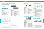
1
EVERFOCUS 560 TVL True Day/Night Indoor Vandal Color Camera Operation Instructions Model No. ED550 Please read this manual first for correct installation and operation. This manual should be retained for future reference. The information in this manual was current when published. The manufacturer reserves the right to revise and improve its products. All specifications are therefore subject to change without notice. PRECAUTIONS 1. Do not install the camera near electric or magnetic fields. Install the camera away from TV, radio transmitter, magnet, electric motor, transformer, audio speakers since the magnetic fields generate from above devices will distort the video image. 2. Never disassemble the camera nor put impurities in it. Disassembly or impurities may result in trouble or fire. 3. Never face the camera toward the sun. Direct sunlight or severe ray may cause fatal damage to sensor and internal circuit. 4. Keep the power cord away from wet and never touch the power cord with wet hands. Touching the wet power cord with hands or touching the power cord with wet hands may result in electric shock. 5. Never install the camera in areas exposed to water, oil or gas. Water, oil or gas may result in failure, electric shock or file. 6. Cleaning Do not touch the surface of sensor by hand directly. Use a soft cloth to remove the dirt from the camera body. Use lens tissue or a cotton tipped applicator and ethanol to clean the sensor and the camera lens. 7. Do not operate the camera beyond the specified temperature, humidity or power source ratings. Use the camera at temperatures within 0℃ ~ 40℃ (32℉ ~ 104℉) and 20%~80% Humidity. The input power source is 12VDC/24VAC. TABLE OF CONTENTS 1. PRODUCT OVERVIEW ...................................................................................................... 4 1.1 Main Features ............................................................................................................................................. 4 1.2 Package Contents ....................................................................................................................................... 4 1.3 Specifications ............................................................................................................................................. 5 1.4 Dimensions ................................................................................................................................................. 6 2. NAMES AND FUNCTIONS OF PARTS ............................................................................. 6 2.1 Front Panel ................................................................................................................................................. 6 2.2 Back Panel .................................................................................................................................................. 8 3. INSTALLATION ................................................................................................................... 9 4. CAMERA SETUP OPERATIONS ..................................................................................... 10 4.1 Setup Button ............................................................................................................................................. 10 4.2 Display/Close the user setup menu screen ............................................................................................... 11 5. USER SETUP ....................................................................................................................... 12 5.1 Lens .......................................................................................................................................................... 12 5.2 Shutter ...................................................................................................................................................... 12 5.3 White Balance Control ............................................................................................................................. 14 5.4 Backlight .................................................................................................................................................. 15 5.5 AGC (Auto Gain Control) ........................................................................................................................ 15 5.6 DNR (Dynamic Noise Reduction) ........................................................................................................... 16 5.7 SENS-UP.................................................................................................................................................. 16 5.8 Special ...................................................................................................................................................... 17 5.8.1 CAMERA ID ......................................................................................................................................... 18 5.8.2 COLOR ADJ ......................................................................................................................................... 19 5.8.3 SYNC .................................................................................................................................................... 19 5.8.4 MOTION DETECTION........................................................................................................................ 19 5.8.5 PRIVACY .............................................................................................................................................. 22 5.8.6 MIRROR ............................................................................................................................................... 24 -2- 5.8.7 SHARPNESS ........................................................................................................................................ 24 5.8.8 RESET................................................................................................................................................... 24 5.8.9 RETURN ............................................................................................................................................... 25 5.9 Exit ........................................................................................................................................................... 25 -3- 1. PRODUCT OVERVIEW The new ED550 camera is designed with advanced new generation 16-bit DSP which has powerful processing capability to show over 560TVL horizontal resolution. Built-in DNR (Dynamic Noise Reduction) function, the camera performs clear & crisper image in low light and substantial disk-saving effect. In addition, designed with SENS-UP slow shutter technology, the starlight super-high sensitivity of 0.002 Lux is achieved. There are two models, one is Day/Night model, the other one is True Day/Night with ICR module. 1.1 Main Features Excellent super high resolution technology with 560 TVL Advanced 16-bit Digital Signal Processor (DSP) delivers excellent picture quality and performance True Day/Night function with IR cut filter (ED550T) Day/Night function (ED550D) Built-in DNR (Dynamic Noise Reduction) for noise reduction and a 70% saving of disk storage The starlight Super-high sensitivity of 0.002 lux/F=1.2 is achieved by setting SENS-UP Shutter X128 Vandal proof to withstand the impact of a 10 lbs sledgehammer Support Motion Detection and Privacy function 1.2 Package Contents Standard accessories Camera Unit x 1 Accessory Pack includes: - Screws x 3 - Expanding Screws x 3 - Hexagon wrench x 1 Manual x 1 Optional accessory Wall Mount bracket (BA-EDMS) -4- 1.3 Specifications Pickup Device Video Format Scanning System Picture Elements Horizontal Resolution Sensitivity S/N Ratio Electronic Shutter Lens Type True Day/Night: Back Light Comp. Auto Gain Control DNR Auto White Balance Gamma Correction Flickerless Video Output Sync. Mode Motion Detection: Privacy Feature: H-Mirror OSD Menu Vandal Resistant Power Source Power Consumption Dimensions Weight Operating Temperature Certifications 1/3'' SONY Super HAD CCD NTSC or PAL NTSC: 525 TV lines, 60 fields/sec PAL: 625 TV lines, 50 fields/sec 768 x 494 (NTSC) ; 752 x 582 (PAL) 560 TVL 0.002Lux (SEN-UP 128x) ; 0.25Lux/ F=1.2 Over 50dB (AGC off) 1/50(1/60)~1/100,000 Vari-focal lens, Auto Iris f=2.9~10mm, F=1.2 f=9~22mm, F=1.6 *Lens models and availability vary in different regions Yes (Auto IR cut filter and B/W Sensitivity Enhanced) Yes, Off/Low/Middle/High selectable Yes, Off/Low/Middle/High selectable Yes, Off/Low/Middle/High selectable ATW(2500~8300 °k)/AWC/Manual 0.45 Yes 2 video outputs BNC 1.0Vp-p, 75ohm Additional testing video output 1.0Vp-p, 75ohm Line Lock/Internal sync Off/On (4-zone, position/size/tone) Off/On (4-zone, position/size/tone) Yes Yes Yes 12VDC/24VAC 24VAC: 2.5W max 12VDC: 3.5W max 120mm(O.D.) x 100mm(H); 4.7"(O.D.) x 3.9"(H) 0.7 kg ; 1.5 lbs 0°C~40°C ; 32°F~104°F (20%~80% Humidity) FCC/CE -5- 1.4 Dimensions 2. NAMES AND FUNCTIONS OF PARTS 2.1 Front Panel Internal Sensor Note: Internal Sensor is a Day/Night Switch Sensor. -6- -7- 2.2 Back Panel (6) (5) (1) (2) (3) (4) (7) (1) Power Input Terminal & Video Output Connector Connect to the appropriate power to each model. Video Output connector is for connecting the video output of the camera to a color monitor or other video devices through a 75 Ohm type coaxial cable with BNC female connector at backside of the camera. (2) Second Video Output Connector When installing the camera, you can use second video connector to connect a portable monitor, this will allow you to easily adjust camera’ angle. (3) Adjust the Switch to Left direction (4) Adjust the Switch to Down direction (5) Adjust the Switch to Right direction (6) Adjust the Switch to Up direction (7) Press the button for on-screen setting menu -8- 3. INSTALLATION Take off camera's cover first. Fix 3 screws of the bracket firmly to wall or ceiling. Adjust the camera to best angle for viewing. Use the tact switcher at the back panel to make any adjustment if needed. Finally, place the cover back to the camera. Ceiling Mount Wall Mount -9- 4. CAMERA SETUP OPERATIONS This camera utilizes an On Screen Display (OSD) user setup menu. 4.1 Setup Button To set items on the user setup menu, use the following switch on the back panel. z Up: Adjust the switch to move the cursor upwards. This is used to select the item need to be set. z Down: Adjust the switch to move the cursor downwards. This is used to select the item need to be set. z Right: Adjust the switch to right direction. This is used to select or adjust the parameters of the selected item. z Left: Adjust the switch to left direction. This is used to select or adjust the parameters of the selected item. z Set button: This button is used to enter setup menu. If the item has its own setting menu (sign ), press this button again to display the setup menu. - 10 - 4.2 Display/Close the user setup menu screen SETUP > LENS SHUTTER WHITE BAL. BACKLIGHT AGC DNR SENS-UP SPECIAL <┘ EXIT Set button DC <┘ ___ ATW OFF MIDDLE LOW AUTO <┘ I. Press the SET button The menu screen will appear on the monitor as the block shown above. II. Using the cursor switch Adjust the switch c or d to move the cursor up or down. Move the switch e or f to adjust the mode or parameter of settings. III. Switch to sub-menu screens When the item with sub-menu is selected, press the SET button to switch to the sub-menu for further settings. Please refer to the figure below. SETUP > LENS SHUTTER WHITE BAL. BACKLIGHT AGC DNR SENS-UP SPECIAL <┘ EXIT LENS DC <┘ ___ ATW OFF MIDDLE LOW AUTO <┘ LEVEL |+++++++++| 20 Sub-Menu Main Menu NOTE: For those selected items with “ settings. ” sign in the end, they have the sub-menu for further IV. Return to previous page Press SET button to return to previous page. V. Close the menu screen To close the menu screen, move the cursor to select EXIT and press the SET button. - 11 - 5. USER SETUP 5.1 Lens 1. When the SETUP menu is displayed on the screen, please direct the arrow to point to “LENS” by adjusting the switch to UP or DOWN direction. SETUP > LENS SHUTTER WHITE BAL. BACKLIGHT AGC DNR SENS-UP SPECIAL <┘ EXIT LENS DC <┘ ___ ATW OFF MIDDLE LOW AUTO <┘ LEVEL |+++++++++| 20 NOTE: 1.ED550 does not support Manual lens, please do not select lens to Manual mode, as it may cause malfunction of lens. 2. The brightness of the screen can be adjusted on DC mode in LENS LEVEL. The level can be adjusted from 1 to 70. 2. Please press SET button if you would like to return to the previous menu. 5.2 Shutter Auto or manual control can be selected. 1. When the SETUP menu is displayed on the screen, please direct the arrow to point to “SHUTTER” by adjusting the switch to DOWN direction. 2. Select the shutter mode by adjusting the switch to LEFT or RIGHT direction. Ö FLK: Please select “FLK” mode when flickering occurs on the screen, because of an irregular balance between illumination and frequency. NTSC model: 1/100, PAL model: 1/120. - 12 - SETUP LENS > SHUTTER WHITE BAL. BACKLIGHT AGC DNR SENS-UP SPECIAL <┘ EXIT MANUAL FLK ATW OFF MIDDLE LOW ___ Ö ESC: The shutter speed can automatically be controlled. When ESC mode turns on, the auto control of the shutter speed can be performed according to the brightness of the screen. The range of ESC is 1 ~ 70. SETUP LENS > SHUTTER WHITE BAL. BACKLIGHT AGC DNR SENS-UP SPECIAL <┘ EXIT MANUAL ESC <┘ ATW OFF MIDDLE LOW AUTO <┘ BRIGHTNESS BRIGHTNESS |+++++++++| 25 Ö Manual: Please select “MANUAL” if you would like to control the shutter manually. SETUP LENS > SHUTTER WHITE BAL. BACKLIGHT AGC DNR SENS-UP SPECIAL <┘ EXIT MANUAL MANUAL <┘ ATW OFF MIDDLE LOW ___ SHUTTER > MANUAL 1/50 3. Press SET button when you finish all the settings. NOTE: 1.When selecting DC lens, the shutter speed is fixed as 1/60 for NTSC and 1/50 for PAL. 2.When “MANUAL” mode is on, the SENS-UP function will be disabled. - 13 - 5.3 White Balance Control The screen color can be adjusted by using the WHITE BALANCE function. 1. Please direct the arrow to point to “WHITE BAL” on the SETUP menu by adjusting the switch to UP or DOWN direction. 2. Please select the mode you would like to operate by adjusting the switch to LEFT or RIGHT direction. Please select one of the 3 modes below: Ö ATW (Auto Tracking White Balance): This mode can be used within the color temperature range from 2,500°K to 8,300°K (eg, fluorescent light, outdoor, sodium vapor lamp or inside tunnels). Ö AWC (Auto White Balance Control): Press the SET button while the camera is directed at a piece of white paper to get the optimum state under the present illumination. If the environment and the light source are changed, you need to adjust the white balance again. Ö MANUAL: The manual adjustment mode enables a more precise adjustment. Please select ATW or AWC first. Then change to manual adjustment mode and press the SET button. Set the suitable color temperature, and increase or decrease the red and blue color values at the same time while checking the color changes of the object. SETUP LENS SHUTTER > WHITE BAL. BACKLIGHT AGC DNR SENS-UP SPECIAL <┘ EXIT WHITE BAL. DC <┘ ___ MANUAL <┘ OFF MIDDLE LOW AUTO <┘ RED BLUE |+++++++++| 32 |+++++++++| 39 NOTE: Under the following conditions, the WHITE BALANCE function may not operate well. In such cases, please select the AWC mode. 1. When the object’s surroundings have a high color temperature. 2. When the object’s surroundings are dark. 3. If the camera faces a fluorescent light directly or is installed in a place where the illumination changes constantly, the WHITE BALANCE function may become unstable. - 14 - 5.4 Backlight Even there is a massive backlight behind the object, bright images of the background and the object can still be obtained by using the BACKLIGHT function. 1. Please direct the arrow to point to “BACKLIGHT” on the SETUP menu by adjusting the switch to UP or DOWN direction. 2. Select the mode you would like to operate by adjusting the switch to LEFT or RIGHT direction. SETUP LENS SHUTTER WHITE BAL. > BACKLIGHT AGC DNR SENS-UP SPECIAL <┘ EXIT Ö Ö Ö Ö DC <┘ ___ ATW OFF MIDDLE LOW AUTO <┘ HIGH: The gain increases from 0dB up to 42dB. MIDDLE: The gain increases from 0dB up to 30dB. LOW: The gain increases from 0dB up to 18dB. OFF: BACKLIGHT function does not operate. 5.5 AGC (Auto Gain Control) 1. Please direct the arrow to point to “AGC” on the SETUP menu by adjusting the switch to UP or DOWN direction. 2. Select the mode you would like to operate by adjusting the switch to LEFT or RIGHT direction. The more the level of gain increases, the brighter the screen and the level of noise increases as well. Ö HIGH: The gain increases from 6dB up to 42dB. Ö MIDDLE: The gain increases from 6dB up to 30dB. Ö LOW: The gain increases from 6dB up to 18dB. Ö OFF: The gain is fixed at 6dB. SETUP LENS SHUTTER WHITE BAL. BACKLIGHT > AGC DNR SENS-UP SPECIAL <┘ EXIT DC <┘ ___ ATW OFF MIDDLE LOW AUTO <┘ - 15 - 5.6 DNR (Dynamic Noise Reduction) Dynamic Noise Reduction in video images has the following effects. 1. Images are brighter and sharper. 2. When the level of noise is reduced, the performance of a camera can apparently be improved. 3. When it is recorded digitally, reduced noise can reduce image file size. As the level of gain changes, the background noise in the low light level automatically decreases. 1. Please direct the arrow to point to “DNR” on the SETUP menu by adjusting the switch to UP or DOWN direction. 2. Select the mode you would like to operate by adjusting the switch to LEFT or RIGHT direction. SETUP LENS SHUTTER WHITE BAL. BACKLIGHT AGC > DNR SENS-UP SPECIAL <┘ EXIT DC <┘ ___ ATW OFF MIDDLE LOW AUTO <┘ Ö OFF: No reduction in noise level. Ö LOW: Little reduction in noise level with nearly no ghost image. Default value is LOW. Ö MIDDLE: Just enough reduction in noise levels without causing much ghost imaging. Ö HIGH: Huge reduction in noise level, which may cause much ghost imaging. NOTE: When AGC is turned off, DNR will be disabled. 5.7 SENS-UP SENS UP is used to keep a brilliant, vivid screen image by automatically detecting changes in the level of light under low light level conditions. 1. Please direct the arrow to point to “SENS UP” on the SETUP menu by adjusting the switch to UP or DOWN direction. 2. Select the mode you would like to operate by adjusting the switch to LEFT or RIGHT direction. Ö AUTO: Low light level auto mode. Default value is AUTO (Up to X 10). - 16 - SETUP LENS SHUTTER WHITE BAL. BACKLIGHT AGC DNR > SENS-UP SPECIAL <┘ EXIT LIMIT DC <┘ ___ ATW OFF MIDDLE LOW AUTO <┘ > AUTO X 10 Ö OFF: The function is disabled. NOTE: 1. When SHUTTER is in the manual mode, SENS UP will be disabled. 2. When AGC is turned off, SENS-UP will be disabled. 2. Press SET button when you finish all the settings. NOTE: 1. The maximum storage magnification in low light level movement situations can be adjusted by pressing the SETUP button in “AUTO” mode. 2. The screen becomes brighter when the magnification increases; yet the after image increases as well. 3. Please be noted that spots and noise may appear if storage magnification increases when SENS-UP is operating. This is a normal phenomenon. 5.8 Special 1. Please direct the arrow to point to “SPECIAL” on the SETUP menu by adjusting the switch to UP or DOWN direction. SETUP LENS SHUTTER WHITE BAL. BACKLIGHT AGC DNR SENS-UP > SPECIAL <┘ EXIT DC <┘ ___ ATW OFF MIDDLE LOW AUTO <┘ 2. Select the mode you would like to operate by adjusting the switch to LEFT or RIGHT direction. - 17 - SPECIAL > CAMERA ID COLOR ADJ. <┘ SYNC. MOTIION DET PRIVACY MIRROR SHARPNESS RESET RETURN <┘ OFF INT OFF OFF OFF ON <┘ 5.8.1 CAMERA ID Input the camera ID, and it will be appeared on the monitor. 1) Please direct the arrow to point to “CAMERA” by adjusting the switch to UP or DOWN direction. 2) Select “ON” by adjusting the switch to LEFT or RIGHT direction. 3) Press SET button. 4) Maximum 15 letters can be used for the ID. ¾ Adjust the switch to UP or DOWN direction to move the cursor to the letter to be chosen. ¾ Adjust the switch to UP, DOWN, LEFT and RIGHT direction to select an ID. ¾ Use SET button to lock in the letters. 5) Once a name has been selected, please choose a position where you would like to display the name. ¾ Move the cursor onto “POS” and press the SET button. ¾ The name will appear at the top left hand corner. ¾ Please adjust the switch toward 4 directions to find the desired position to display the name. 6) If you would like to cancel the ID inputted, please move the cursor to “CLR”, and all the letters inputted will be deleted. 7) Select “END” and press SET button to complete ID input. SPECIAL > CAMERA ID COLOR ADJ. <┘ SYNC. MOTIION DET PRIVACY MIRROR SHARPNESS RESET RETURN <┘ ON INT OFF OFF OFF ON <┘ CAMERA ID A N a n - B O b o · <- -> C P c p D Q d q 0 E R e r 1 F S f s 2 CLR G T g t 3 H U h u 4 I V i v 5 J W j w 6 POS _______________ - 18 - K X k x 7 L Y l y 8 M Z m z 9 END 5.8.2 COLOR ADJ Adjust the Color Gain from 0 ~ 15 SPECIAL CAMERA ID > COLOR ADJ. <┘ SYNC. MOTIION DET PRIVACY MIRROR SHARPNESS RESET RETURN <┘ OFF COLOR GAIN. INT OFF OFF OFF ON <┘ > LEVEL |++++++++| 8 5.8.3 SYNC There are two SYNCHRONIZATION modes: INTERNAL and EXTERNAL LINE-LOCK. In LINE-LOCK mode, without a synchronous generator, it synchronizes the video signal between cameras. The Line-Lock synchronization is only used in the places of 60Hz (NTSC models) or 50Hz (PAL models). -INT: Internal synchronization -LL: External line-lock synchronization => If you choose “LL”, you can adjust the phase your wish to set. Then press the SET button. You can adjust the phase you wish to set from 0 to 359. SPECIAL CAMERA ID COLOR ADJ. <┘ > SYNC. MOTIION DET PRIVACY MIRROR SHARPNESS RESET RETURN <┘ OFF SYNC LL <┘ OFF OFF OFF ON <┘ > PHASE |++++++++| 0 5.8.4 MOTION DETECTION ED550 camera enables you to observe movements of objects in 4 different places on the screen, the message “MOTION DETECTED” appears on the screen when movement is detected; therefore this helps to improve supervision efficiency. The camera detects an object’s movement by sensing discrepancy of outline. 1) Please direct the arrow to point to “MOTION DET” by adjusting the switch to UP or DOWN direction. 2) Select “ON” by adjusting the switch to LEFT or RIGHT direction. 3) Press SET button. - 19 - SPECIAL MOTION DETECTION CAMERA ID COLOR ADJ. <┘ SYNC. > MOTIION DET PRIVACY MIRROR SHARPNESS RESET RETURN <┘ OFF > AEREA SEL AREA STATE TOP INT ON <┘ OFF OFF ON <┘ DOWN LEFT RIGHT AREA1 ON |+++++++++| 10 |+++++++++| 25 |+++++++++| 20 |+++++++++| 40 z Please select the area you would like to detect from the 4 areas in AREA SEL mode. z Please select ON mode for the chosen area. z Please adjust the switch to UP or DOWN direction to move between TOP, DOWN, LEFT and RIGHT for adjusting the size of the area to be detected. z Please adjust the switch to LEFT or RIGHT direction to adjust the value for size of the area to be detected. AREA1 AREA2 AREA3 AREA4 z Additionally, it is possible to change the position of the area to be detected. Please refer to the following example for detailed steps on moving AREA1 to center. 1. The original position of AREA1 was TOP: 10, DOWN: 25, LEFT: 20 and RIGHT: 40. AREA1 - 20 - 2. Increase DOWN scale value by 20. AREA1 position after change is: TOP: 10, DOWN: 45, LEFT: 20 and RIGHT: 40. AREA1 3. Increase TOP scale value by 20. AREA1 position after change is: TOP: 30, DOWN: 45, LEFT: 20 and RIGHT: 40. AREA1 4. Increase RIGHT scale value by 20. AREA1 position after change is: TOP: 30, DOWN: 45, LEFT: 20 and RIGHT: 60. AREA1 5. Increase LEFT scale value by 20. AREA1 position after change is: TOP: 30, DOWN: 45, LEFT: 40 and RIGHT: 60. AREA1 z In order to save the changes and complete the setting, press the SET button. This allows you to return to the previous menu. - 21 - 5.8.5 PRIVACY This mode covers the areas you do not want to see on the screen. 1) Please direct the arrow to point to “PRIVACY” by adjusting the switch to UP or DOWN direction. 2) Select “ON” by adjusting the switch to LEFT or RIGHT direction. 3) Press SET button. SPECIAL CAMERA ID COLOR ADJ. <┘ SYNC. MOTIION DET > PRIVACY MIRROR SHARPNESS RESET RETURN <┘ PRIVACY OFF > AEREA SEL AREA STATE. AREA TONE TOP DOWN LEFT RIGHT INT OFF ON <┘ OFF ON <┘ AREA1 OFF |+++++++++| 80 |++++++++| 10 |+++++++++| 25 |+++++++++| 20 |+++++++++| 40 z Please select the area you would like to cover from the 4 areas in AREA SEL mode. z Please select ON mode for the chosen area. z Please select AREA TONE for cover area. The larger the number, the lighter the cover area. z Please adjust the switch to UP or DOWN direction to move between TOP, DOWN, LEFT and RIGHT for adjusting the size of the area to be covered. z Please adjusting the switch to LEFT or RIGHT direction to adjust the value for size of the area to be covered. AREA1 AREA2 AREA3 AREA4 z Additionally, it is possible to change the position of the area to be covered. Please refer to the following example for detailed steps on moving AREA1 to center. - 22 - 1. The original position of AREA1 was TOP: 10, DOWN: 25, LEFT: 20 and RIGHT: 40. AREA1 2. Increase DOWN scale value by 20. AREA1 position after change is: TOP: 10, DOWN: 45, LEFT: 20 and RIGHT: 40. AREA1 3. Increase TOP scale value by 20. AREA1 position after change is: TOP: 30, DOWN: 45, LEFT: 20 and RIGHT: 40. AREA1 4. Increase RIGHT scale value by 20. AREA1 position after change is: TOP: 30, DOWN: 45, LEFT: 20 and RIGHT: 60. AREA1 5. Increase LEFT scale value by 20. AREA1 position after change is: TOP: 30, DOWN: 45, LEFT: 40 and RIGHT: 60. AREA1 - 23 - z In order to save the changes and complete the setting, press the SET button. This allows you to return to the previous menu. 5.8.6 MIRROR -ON: Sets a horizontal image inversion. -OFF: Disable the inversion. SPECIAL CAMERA ID COLOR ADJ. <┘ SYNC. MOTIION DET PRIVACY > MIRROR SHARPNESS RESET RETURN <┘ OFF INT OFF OFF OFF ON <┘ 5.8.7 SHARPNESS The contour of the video image becomes cleaner and more distinguishing as the level of SHARPNESS increases. If the level goes up extremely, it may affect the video image and cause noise. -ON: Enable the SHARPNESS mode. -OFF: Disable the SHARPNESS mode. z Please press the SET button. z The available range of level is 0~31. SPECIAL CAMERA ID COLOR ADJ. <┘ SYNC. MOTIION DET PRIVACY MIRROR > SHARPNESS RESET RETURN <┘ SHARPNESS OFF > LEVEL INT OFF OFF OFF ON <┘ 5.8.8 RESET Reset to the default level. SPECIAL CAMERA ID COLOR ADJ. <┘ SYNC. MOTIION DET PRIVACY MIRROR SHARPNESS > RESET RETURN <┘ OFF INT OFF OFF OFF ON <┘ - 24 - |+++++++++| 8 5.8.9 RETURN It saves all settings in SPECIAL menu and returns to the SETUP menu. SPECIAL CAMERA ID COLOR ADJ. <┘ SYNC. MOTIION DET PRIVACY MIRROR SHARPNESS RESET > RETURN <┘ OFF INT OFF OFF OFF ON <┘ 5.9 Exit Save all the setting menus and exit. NOTE: If you quit the Menu without pressing EXIT, all the settings you previously did will NOT be saved. - 25 - EverFocus Electronics Corp. Head Office: 12F, No.79 Sec. 1 Shin-Tai Wu Road, Hsi-Chih, Taipei, Taiwan TEL: +886-2-26982334 FAX: +886-2-26982380 www.everfocus.com.tw USA L.A. Office: 1801 Highland Ave. Unit A Duarte, CA 91010, U.S.A. TEL: +1-626-844-8888 FAX: +1-626-844-8838 www.everfocus.com USA N.Y. Office: 415 Oser Avenue Unit S Hauppauge, NY 11788 TEL: 631-436-5070 FAX: 631-436-5027 www.everfocus.com Your EverFocus product is designed and manufactured with high quality materials and components which can be recycled and reused. This symbol means that electrical and electronic equipment, at their end-of-life, should be disposed of separately from your household waste. Please, dispose of this equipment at your local community waste collection/recycling centre. In the European Union there are separate collection systems for used electrical and electronic product. Please, help us to conserve the environment we live in! Europe Office: Albert-Einstein-Strasse 1 D-46446 Emmerich, Germany TEL: 49-2822-9394-0 www.everfocus.de China Office: Room B-05D-1, KESHI PLAZA, Shangdi Information Industry Base, Haidian District, Beijing China 100085 TEL: +86-10-62973336/37/38/39 FAX: +86-10-62971423 www.everfocus.com.cn Japan Office: 1809 WBG MARIBU East 18F, 2-6 Nakase.Mihama-ku. Chiba city 261-7118, Japan TEL: +81-43-212-8188 FAX: +81-43-297-0081 www.everfocus.com Ihr EverFocus Produkt wurde entwickelt und hergestellt mit qualitativ hochwertigen Materialien und Komponenten, die recycelt und wieder verwendet werden können. Dieses Symbol bedeutet, dass elektrische und elektronische Geräte am Ende ihrer Nutzungsdauer vom Hausmüll getrennt entsorgt werden sollen. Bitte entsorgen Sie dieses Gerät bei Ihrer örtlichen kommunalen Sammelstelle oder im Recycling Centre. Helfen Sie uns bitte, die Umwelt zu erhalten, in der wir leben! P/N: MED5G00500_Ver. B - 26 -