1
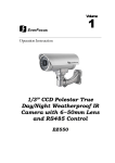
EVERFOCUS 1/3” Super High Resolution 560 TVL Day/Night Dynamic Noise Reduction Camera Operation Instructions Model No. EQ550 Please read this manual first for correct installation and operation. This manual should be retained for future reference. The information in this manual was current when published. The manufacturer reserves the right to revise and improve its products. All specifications are therefore subject to change without notice. PRECAUTIONS 1. Do not install the camera near electric or magnetic fields. Install the camera away from TV, radio transmitter, magnet, electric motor, transformer, audio speakers since the magnetic fields generate from above devices will distort the video image. 2. Never disassemble the camera nor put impurities in it. Disassembly or impurities may result in trouble or fire. 3. Never face the camera toward the sun. Direct sunlight or severe ray may cause fatal damage to sensor and internal circuit. 4. Keep the power cord away from wet and never touch the power cord with wet hands. Touch the wet power cord with hands or touch the power cord with wet hands may result in electric shock. 5. Never install the camera in areas exposed to water, oil or gas. Water, oil or gas may result in failure, electric shock or file. 6. Cleaning Do not touch the surface of sensor by hand directly. Use a soft cloth to remove the dirt from the camera body. Use lens tissue or a cotton tipped applicator and ethanol to clean the sensor and the camera lens. 7. Do not operate the camera beyond the specified temperature, humidity or power source ratings. Use the camera at temperatures within 0℃ ~ 50℃ (32℉~122℉) and humidity between 20~80%. The input power source is 12VDC/24VAC or 100~ 240VAC. TABLE OF CONTENTS 1. PRODUCT OVERVIEW ................................................................................................................................... 3 1.1 MAIN FEATURES .............................................................................................................................................. 3 2. NAMES AND FUNCTIONS OF PARTS .......................................................................................................... 4 2.1 FRONT PANEL ................................................................................................................................................... 4 2.2 TOP/BOTTOM ................................................................................................................................................... 4 2.3 BACK PANEL CONNECTIONS ............................................................................................................................. 5 3. INSTALLATION ................................................................................................................................................ 7 4. CONNECTION ................................................................................................................................................... 8 5. CAMERA SETUP OPERATIONS .................................................................................................................... 9 5.1 SETUP BUTTONS .............................................................................................................................................. 9 5.2 DISPLAY/CLOSE THE USER SETUP MENU SCREEN ............................................................................................ 10 6. USER SETUP .................................................................................................................................................... 11 6.1 LENS ............................................................................................................................................................ 11 6.2 SHUTTER .................................................................................................................................................... 11 6.3 WHITE BALANCE CONTROL ...................................................................................................................... 13 6.4 BACKLIGHT ............................................................................................................................................... 14 6.5 AGC (AUTO GAIN CONTROL) ........................................................................................................................ 14 6.6 DNR (DYNAMIC NOISE REDUCTION) ............................................................................................................ 15 6.7 SENS-UP ...................................................................................................................................................... 15 6.8 SPECIAL ...................................................................................................................................................... 16 6.8.1 CAMERA ID .......................................................................................................................................... 17 6.8.2 COLOR ADJ .......................................................................................................................................... 18 6.8.3 SYNC ..................................................................................................................................................... 18 6.8.4 MOTION DETECTION ......................................................................................................................... 18 6.8.5 PRIVACY ............................................................................................................................................... 21 6.8.6 MIRROR ................................................................................................................................................ 23 6.8.7 SHARPNESS .......................................................................................................................................... 23 6.8.8 RESET ................................................................................................................................................... 24 6.8.9 RETURN ................................................................................................................................................ 24 6.9 EXIT ............................................................................................................................................................. 24 7. POLESTAR WITH RS485 MINI DIN ............................................................................................................ 25 7.1 RS485 COMMUNICATION & CONTROL PIN.................................................................................................... 25 7.2 KEY FEATURES WITH RS485 .......................................................................................................................... 26 7.3 HOW TO SET RS485 ID & BAUD RATE? .......................................................................................................... 26 7.4 CONTROL BY KEYBOARD ............................................................................................................................... 27 7.5 DAY/NIGHT MODE SETTING FROM KEYBOARD ............................................................................................... 27 7.6 DAY/NIGHT CONTROL BY EXTERNAL D/N SIGNAL ......................................................................................... 28 7.7 TO CONTROL EXTERNAL D/N SIGNAL............................................................................................................. 28 7.8 ALARM OUTPUT FOR MOTION DETECTED ....................................................................................................... 29 8. SPECIFICATIONS ........................................................................................................................................... 30 -1- 9. CONTENT LIST ............................................................................................................................................... 31 -2- 1. PRODUCT OVERVIEW The new EQ550 Polestar is designed with advanced new generation 16-bit DSP which has powerful processing capability to show over 560TVL horizontal resolution. Built-in DNR (Dynamic Noise Reduction) function, the EQ550 performs clear & crisper image in low light and substantial disk-saving effect. In addition, designed with SENS-UP slow shutter technology, the starlight super-high sensitivity of 0.002 Lux is achieved. There are two models, one is Day/Night model, the other one is True Day/Night with ICR module. With RS485 port, you can even control EQ550 Polestar by a keyboard. 1.1 Main Features 1/3” SONY Super HAD color CCD pick up device for more than 560 TV lines of horizontal resolution . Advanced 16-bit Digital Signal Processor (DSP) delivers excellent picture quality and performance Day/Night function (EQ550D) True Day/Night function with ICR module (EQ550T) Built-in DNR (Dynamic Noise Reduction) for noise reduction and a 70% saving of Disk storage The starlight Super-high sensitivity of 0.002 Lux/F=1.2 is achieved by setting SENS-UP Shutter X128 0 Lux (IR LED on, if IR illuminator is used) OSD setting menu Support Motion Detection function Provides alarm output for motion detected Support Privacy function High sensitivity designed with SONY sensor Support either C-mount or CS-mount (Optional) Support RS485 for keyboard control (for a certain protocol of keyboard only) Receive external D/N signal to drive a synchronized control of Polestar’s D/N. (apply to housing that has IR LED) Send out D/N signal to other external D/N control. (apply to housing that has IR LED) -3- 2. NAMES AND FUNCTIONS OF PARTS 2.1 Front panel Microphone (Reserved only for Audio model) Internal Sensor 2.2 Top/Bottom The bracket on the top side can be used for suspending the camera. On the other hand, the brackets on the bottom side can be used as a support of the camera. Bottom Bracket Top Bracket -4- 2.3 Back panel connections (12) (4) (10) (8) (7) 485 (6) (1) (5) (9) (3) (11) (2) (13) (1) RS-485 port Connect to RS485 to get control by keyboard. Please refer to “6. Polestar with RS485 Mini Din” for detail about RS485 communication. (2) Power Input Terminal Connects to the appropriate power to each model. (3) Video Output Connector Connect the video output of the camera to a color monitor or other video devices through a 75 Ohm type coaxial cable with BNC female connector at backside of the camera. (4) Tact switcher for left cursor (5) Tact switcher for down cursor (6) Tact switcher for right cursor (7) Tact switcher for up cursor (8) Tact switcher for on-screen setting menu -5- (9) Audio Output Connector (for Audio model only) (10) Switch: For True Day/Night model with ICR (EQ550T) H: IR cut filter is removed when illumination is low (about 5 Lux) L: IR cut filter is removed when illumination is the lowest (Less than 2 Lux) OFF: Disable the function of IR cut removable For Day/Night model without ICR (EQ550D) H: Enabling the image to turn from color to B/W when the illumination is about 5 Lux L: Enabling the image to turn from color to B/W when the illumination is about 2 Lux OFF: Day/Night function is disabled (11) LED Red- Power on, Green- Low light condition detected. 1. IR cut filter will be removed in about 5-10 sec (for EQ550T). 2. Entering the Night mode, which makes the image to turn from color to B/W (for both EQ550D & EQ550T). (12) External sensor connector If user wants to change the location of IR light sensor, he/she can use an External light sensor to connect to this port. (Note: External light sensor kit is an optional product). When this External sensor port is used, the External sensor will be the default IR light sensor. (13) Auto Iris Lens Connector This connector is used to connect with the auto iris lens by a 4 pin male connector Pin 1 Pin 2 Pin 3 Pin 4 3 4 1 2 Direct Drive CntCnt+ Drv+ Drv- -6- 3. INSTALLATION 1. Remove the cover cap from the top of the lens mount. 2. If C mount lens is used, please add the C adaptor mount ring (the 5mm thick ring in the accessory pack) on top of the lens mount. 3. Mount the lens by turning it clockwise on the lens mount of the camera. 4. If you use the Auto Iris lens, connecting the lens cable to the auto iris lens connector on the side of the camera. 5. Place ND filter in front of the lens, adjust lens focus until best image is obtained. 6. Fix lens focus by turning tightly the swivel, then remove ND filter. Mount the lens Use ND filter -7- 4. CONNECTION 485 1. Connect the cable from keyboard’s RS485 port to camera’s RS485 port. 2. Connect the cable from video output jack of the camera to monitor’s input jack. 3. RS485 ID of Polestar has to be the same as CAM ID of the keyboard. (Please refer to “6.3 How to set RS485 ID & Baud rate?” for RS485 ID setup detail) 4. Baud rate of Polestar has to be the same as Keyboard’s baud rate. (Please refer to “6.3 How to set RS485 ID & Baud rate?” for baud rate setup detail) -8- 5. CAMERA SETUP OPERATIONS This camera utilizes an On Screen Display (OSD) user setup menu. 5.1 Setup Buttons To set items on the user setup menu, use the following buttons on the back panel. ④ Left Button ① Up Button ⑤ Set Button 485 ③ Right Button ② Down Button ① Up Button: This button is used to move the cursor upwards. Use this button to select the item wanted to set. ② Down Button: This button is used to move the cursor downwards. Use this button to select the item wanted to set. ③ Right Button: Use this button to select or adjust the parameters of the selected item. The parameter changes each time as this button is pressed. ④ Left Button: Use this button to select or adjust the parameters of the selected item. The parameter changes each time as this button is pressed. ⑤ Set Button: This button is used to enter setup menu. If the item has its own setting menu (sign ), press this button again to display the setup menu. -9- 5.2 Display/Close the user setup menu screen SETUP Set button DC <┘ ___ ATW OFF MIDDLE LOW AUTO <┘ > LENS SHUTTER WHITE BAL. BACKLIGHT AGC DNR SENS-UP SPECIAL <┘ EXIT The Cursor Buttons & the SET Button I. Press the SET button The menu screen will appear on the monitor as the block shown above. II. Using the cursor button Use the cursor button c or d to move the cursor up or down. Use the cursor button e or f to adjust the mode or parameter of settings. III. Switch to sub-menu screens When the item with sub-menu is selected, press the SET button to switch to the sub-menu for further settings. Please refer to the figure below. SETUP > LENS SHUTTER WHITE BAL. BACKLIGHT AGC DNR SENS-UP SPECIAL <┘ EXIT LENS DC <┘ ___ ATW OFF MIDDLE LOW AUTO <┘ LEVEL |+++++++++| 20 Sub-Menu Main Menu NOTE: For those selected items with “ settings. ” sign in the end, they have the sub-menu for further IV. Return to previous page Press the SET button to return to previous page. V. Close the menu screen To close the menu screen, use the cursor button to select EXIT and press the SET button. - 10 - 6. USER SETUP 6.1 LENS 1. When the SETUP menu is displayed on the screen, please direct the arrow to point to “LENS” by using the UP and DOWN buttons. 2. Please select the type of the lens you would like to use by pressing the LEFT or RIGHT button. SETUP > LENS SHUTTER WHITE BAL. BACKLIGHT AGC DNR SENS-UP SPECIAL <┘ EXIT LENS DC <┘ ___ ATW OFF MIDDLE LOW AUTO <┘ LEVEL |+++++++++| 20 NOTE: 1 When using an auto iris lens, the setting of the auto iris lens selection switch, located on ○ the back of the camera, must be on DC or MANUAL depending on the type of the lens which is being used. 2 The brightness of the screen can be adjusted on DC mode in LENS LEVEL. The level ○ can be adjusted from 1 to 70. 3. Please press the SETUP button if you would like to return to the previous menu. 6.2 SHUTTER Auto or manual control can be selected. 1. When the SETUP menu is displayed on the screen, please direct the arrow to point to “SHUTTER” by using the DOWN button. 2. Select the shutter mode by pressing the LEFT or RIGHT button. Ö FLK: Please select “FLK” mode when flickering occurs on the screen, because of an irregular balance between illumination and frequency. NTSC model: 1/100, PAL model: 1/120. - 11 - SETUP LENS > SHUTTER WHITE BAL. BACKLIGHT AGC DNR SENS-UP SPECIAL <┘ EXIT MANUAL FLK ATW OFF MIDDLE LOW ___ Ö ESC: The shutter speed can automatically be controlled. When ESC mode turns on, the auto control of the shutter speed can be performed according to the brightness of the screen. The range of ESC is 1 ~ 70. SETUP LENS > SHUTTER WHITE BAL. BACKLIGHT AGC DNR SENS-UP SPECIAL <┘ EXIT BRIGHTNESS MANUAL ESC <┘ ATW OFF MIDDLE LOW AUTO <┘ BRIGHTNESS |+++++++++| 25 Ö Manual: Please select “MANUAL” if you would like to control the shutter manually. SETUP LENS > SHUTTER WHITE BAL. BACKLIGHT AGC DNR SENS-UP SPECIAL <┘ EXIT SHUTTER MANUAL MANUAL <┘ ATW OFF MIDDLE LOW ___ > MANUAL 1/50 3. Press the SETUP button when you finish all the settings. NOTE: 1 When selecting DC lens, the shutter speed is fixed as 1/60 for NTSC and 1/50 for PAL. ○ 2 When “MANUAL” mode is on, the SENS-UP function will be disabled. ○ - 12 - 6.3 WHITE BALANCE control The screen color can be adjusted by using the WHITE BALANCE function. 1. Please direct the arrow to point to “WHITE BAL” on the SETUP menu by using the UP and DOWN buttons. 2. Please select the mode you would like to operate by pressing the LEFT or RIGHT button. Please select one of the 3 modes below: Ö ATW (Auto Tracking White Balance): This mode can be used within the color temperature range from 2,500°K to 8,300°K (eg, fluorescent light, outdoor, sodium vapor lamp or inside tunnels). Ö AWC (Auto White Balance Control): Press the SETUP button while the camera is directed at a piece of white paper to get the optimum state under the present illumination. If the environment and the light source are changed, you need to adjust the white balance again. Ö MANUAL: The manual adjustment mode enables a more precise adjustment. Please select ATW or AWC first. Then change to manual adjustment mode and press the SETUP button. Set the suitable color temperature, and increase or decrease the red and blue color values at the same time while checking the color changes of the object. SETUP LENS SHUTTER > WHITE BAL. BACKLIGHT AGC DNR SENS-UP SPECIAL <┘ EXIT WHITE BAL. DC <┘ ___ MANUAL <┘ OFF MIDDLE LOW AUTO <┘ RED BLUE |+++++++++| 32 |+++++++++| 39 NOTE: Under the following conditions, the WHITE BALANCE function may not operate well. In such cases, please select the AWC mode. 1 When the object’s surroundings have a high color temperature. ○ 2 When the object’s surroundings are dark. ○ 3 If the camera faces a fluorescent light directly or is installed in a place where the ○ illumination changes constantly, the WHITE BALANCE function may become unstable. - 13 - 6.4 BACKLIGHT Even there is a massive backlight behind the object, bright images of the background and the object can still be obtained by using the BACKLIGHT function. 1. Please direct the arrow to point to “BACKLIGHT” on the SETUP menu by using the UP and DOWN buttons. 2. Select the mode you would like to operate by pressing the LEFT or RIGHT button. SETUP LENS SHUTTER WHITE BAL. > BACKLIGHT AGC DNR SENS-UP SPECIAL <┘ EXIT DC <┘ ___ ATW OFF MIDDLE LOW AUTO <┘ Ö HIGH: The gain increases from 0dB up to 42dB. Ö MIDDLE: The gain increases from 0dB up to 30dB. Ö LOW: The gain increases from 0dB up to 18dB. Ö OFF: BACKLIGHT function does not operate. 6.5 AGC (Auto Gain Control) 1. Please direct the arrow to point to “AGC” on the SETUP menu by using the UP and DOWN buttons. 2. Select the mode you would like to operate by pressing the LEFT or RIGHT button. The more the level of gain increases, the brighter the screen and the level of noise increases as well. Ö HIGH: The gain increases from 6dB up to 42dB. Ö MIDDLE: The gain increases from 6dB up to 30dB. Ö LOW: The gain increases from 6dB up to 18dB. Ö OFF: The gain is fixed at 6dB. SETUP LENS SHUTTER WHITE BAL. BACKLIGHT > AGC DNR SENS-UP SPECIAL <┘ EXIT DC <┘ ___ ATW OFF MIDDLE LOW AUTO <┘ - 14 - 6.6 DNR (Dynamic Noise Reduction) Dynamic Noise Reduction in video images has the following effects. 1. Images are brighter and sharper. 2. When the level of noise is reduced, the performance of a camera can apparently be improved. 3. When it is recorded digitally, reduced noise can reduce image file size. As the level of gain changes, the background noise in the low light level automatically decreases. 1. Please direct the arrow to point to “DNR” on the SETUP menu by using the UP and DOWN buttons. 2. Select the mode you would like to operate by pressing the LEFT or RIGHT button. SETUP LENS SHUTTER WHITE BAL. BACKLIGHT AGC > DNR SENS-UP SPECIAL <┘ EXIT DC <┘ ___ ATW OFF MIDDLE LOW AUTO <┘ Ö OFF: No reduction in noise level. Ö LOW: Little reduction in noise level with nearly no ghost image. Default value is LOW. Ö MIDDLE: Just enough reduction in noise levels without causing much ghost imaging. Ö HIGH: Huge reduction in noise level, which may cause much ghost imaging. NOTE: When AGC is turned off, DNR will be disabled. 6.7 SENS-UP SENS UP is used to keep a brilliant, vivid screen image by automatically detecting changes in the level of light under low light level conditions. 1. Please direct the arrow to point to “SENS UP” on the SETUP menu by using the UP and DOWN buttons. 2. Select the mode you would like to operate by pressing the LEFT or RIGHT button. Ö AUTO: Low light level auto mode. Default value is AUTO (Up to X 10). - 15 - SETUP LENS SHUTTER WHITE BAL. BACKLIGHT AGC DNR > SENS-UP SPECIAL <┘ EXIT LIMIT DC <┘ ___ ATW OFF MIDDLE LOW AUTO <┘ > AUTO X 10 Ö OFF: The function is disabled. NOTE: 1 When SHUTTER is in the manual mode, SENS UP will be disabled. ○ 2 When AGC is turned off, SENS-UP will be disabled. ○ 3. Press the SETUP button when you finish all the settings. NOTE: 1 The maximum storage magnification in low light level movement situations can be ○ adjusted by pressing the SETUP button in “AUTO” mode. 2 The screen becomes brighter when the magnification increases; yet the after image ○ increases as well. 3 Please be noted that spots and noise may appear if storage magnification increases ○ when SENS-UP is operating. This is a normal phenomenon. 6.8 SPECIAL 1. Please direct the arrow to point to “SPECIAL” on the SETUP menu by using the UP and DOWN buttons. SETUP LENS SHUTTER WHITE BAL. BACKLIGHT AGC DNR SENS-UP > SPECIAL <┘ EXIT DC <┘ ___ ATW OFF MIDDLE LOW AUTO <┘ 2. Select the mode you would like to operate by pressing the LEFT or RIGHT button. - 16 - SPECIAL > CAMERA ID COLOR ADJ. <┘ SYNC. MOTIION DET PRIVACY MIRROR SHARPNESS RESET RETURN <┘ OFF INT OFF OFF OFF ON <┘ 6.8.1 CAMERA ID Input the camera ID, and it will be appeared on the monitor. 1) Please direct the arrow to point to “CAMERA” by using the UP or DOWN button. 2) Select “ON” by pressing the LEFT or RIGHT button. 3) Press SETUP button. 4) Maximum 15 letters can be used for the ID. ¾ Use UP and DOWN buttons to move the cursor to the letter to be chosen. ¾ Use UP, DOWN, LEFT and RIGHT buttons to select an ID. ¾ Use SETUP button to lock in the letters. 5) Once a name has been selected, please choose a position where you would like to display the name. ¾ Move the cursor onto “POS” and press the SETUP button. ¾ The name will appear at the top left hand corner. ¾ Please use the 4 directional buttons to find the desired position to display the name. 6) If you would like to cancel the ID inputted, please move the cursor to “CLR”, and all the letters inputted will be deleted. 7) Select “END” and press SETUP button to complete ID input. SPECIAL > CAMERA ID COLOR ADJ. <┘ SYNC. MOTIION DET PRIVACY MIRROR SHARPNESS RESET RETURN <┘ ON INT OFF OFF OFF ON <┘ CAMERA ID A B C D E F G H I J K L M N O P Q R S T U V W X Y Z a b c d e f g h i j k l m n o p q r s t u v w x y z - · 0 1 2 3 4 5 6 7 8 9 <- -> CLR POS _______________ - 17 - END 6.8.2 COLOR ADJ Adjust the Color Gain from 0 ~ 15 SPECIAL CAMERA ID > COLOR ADJ. <┘ SYNC. MOTIION DET PRIVACY MIRROR SHARPNESS RESET RETURN <┘ COLOR GAIN. OFF > LEVEL INT OFF OFF OFF ON <┘ |++++++++| 8 6.8.3 SYNC There are two SYNCHRONIZATION modes: INTERNAL and EXTERNAL LINE-LOCK. In LINE-LOCK mode, without a synchronous generator, it synchronizes the video signal between cameras. The Line-Lock synchronization is only used in the places of 60Hz (NTSC models) or 50Hz (PAL models). -INT: Internal synchronization -LL: External line-lock synchronization => If you choose “LL”, you can adjust the phase your wish to set. Then press the SET button. You can adjust the phase you wish to set from 0 to 359. SPECIAL CAMERA ID COLOR ADJ. <┘ > SYNC. MOTIION DET PRIVACY MIRROR SHARPNESS RESET RETURN <┘ OFF SYNC LL <┘ OFF OFF OFF ON <┘ > PHASE |++++++++| 0 6.8.4 MOTION DETECTION Polestar enables you to observe movements of objects in 4 different places on the screen, the message “MOTION DETECTED” appears on the screen when movement is detected; therefore this helps to improve supervision efficiency. The camera detects an object’s movement by sensing discrepancy of outline. 1) Please direct the arrow to point to “MOTION DET” by using the UP or DOWN button. 2) Select “ON” by pressing the LEFT or RIGHT button. 3) Press SETUP button. - 18 - SPECIAL CAMERA ID COLOR ADJ. <┘ SYNC. > MOTIION DET PRIVACY MIRROR SHARPNESS RESET RETURN <┘ z z z z z MOTION DETECTION OFF > AEREA SEL AREA STATE TOP DOWN LEFT RIGHT INT ON <┘ OFF OFF ON <┘ AREA1 ON |+++++++++| 10 |+++++++++| 25 |+++++++++| 20 |+++++++++| 40 Press SET to return Please select the area you would like to detect from the 4 areas in AREA SEL mode. Please select ON mode for the chosen area. Please use the UP or DOWN button to move between TOP, DOWN, LEFT and RIGHT for adjusting the size of the area to be detected. Please use the LEFT or RIGHT button to adjust the value for size of the area to be detected. AREA1 AREA2 AREA3 AREA4 Additionally, it is possible to change the position of the area to be detected. Please refer to the following example for detailed steps on moving AREA1 to center. 1. The original position of AREA1 was TOP: 10, DOWN: 25, LEFT: 20 and RIGHT: 40. AREA1 - 19 - 2. Increase DOWN scale value by 20. AREA1 position after change is: TOP: 10, DOWN: 45, LEFT: 20 and RIGHT: 40. AREA1 3. Increase TOP scale value by 20. AREA1 position after change is: TOP: 30, DOWN: 45, LEFT: 20 and RIGHT: 40. AREA1 4. Increase RIGHT scale value by 20. AREA1 position after change is: TOP: 30, DOWN: 45, LEFT: 20 and RIGHT: 60. AREA1 5. Increase LEFT scale value by 20. AREA1 position after change is: TOP: 30, DOWN: 45, LEFT: 40 and RIGHT: 60. AREA1 z In order to save the changes and complete the setting, press the SETUP button. This allows you to return to the previous menu. - 20 - 6.8.5 PRIVACY This mode covers the areas you do not want to see on the screen. 1) Please direct the arrow to point to “PRIVACY” by using the UP or DOWN button. 2) Select “ON” by pressing the LEFT or RIGHT button. 3) Press SETUP button. SPECIAL CAMERA ID COLOR ADJ. <┘ SYNC. MOTIION DET > PRIVACY MIRROR SHARPNESS RESET RETURN <┘ PRIVACY OFF > AEREA SEL AREA STATE. AREA TONE TOP DOWN LEFT RIGHT INT OFF ON <┘ OFF ON <┘ AREA1 OFF |+++++++++| 80 |++++++++| 10 |+++++++++| 25 |+++++++++| 20 |+++++++++| 40 z Please select the area you would like to cover from the 4 areas in AREA SEL mode. z Please select ON mode for the chosen area. z Please select AREA TONE for cover area. The larger the number, the lighter the cover area. z Please use the UP or DOWN button to move between TOP, DOWN, LEFT and RIGHT for adjusting the size of the area to be covered. z Please use the LEFT or RIGHT button to adjust the value for size of the area to be covered. z AREA1 AREA2 AREA3 AREA4 Additionally, it is possible to change the position of the area to be covered. Please refer to the following example for detailed steps on moving AREA1 to center. - 21 - 1. The original position of AREA1 was TOP: 10, DOWN: 25, LEFT: 20 and RIGHT: 40. AREA1 2. Increase DOWN scale value by 20. AREA1 position after change is: TOP: 10, DOWN: 45, LEFT: 20 and RIGHT: 40. AREA1 3. Increase TOP scale value by 20. AREA1 position after change is: TOP: 30, DOWN: 45, LEFT: 20 and RIGHT: 40. AREA1 4. Increase RIGHT scale value by 20. AREA1 position after change is: TOP: 30, DOWN: 45, LEFT: 20 and RIGHT: 60. AREA1 - 22 - 5. Increase LEFT scale value by 20. AREA1 position after change is: TOP: 30, DOWN: 45, LEFT: 40 and RIGHT: 60. AREA1 z In order to save the changes and complete the setting, press the SETUP button. This allows you to return to the previous menu. 6.8.6 MIRROR -ON: Sets a horizontal image inversion. -OFF: Disable the inversion. SPECIAL CAMERA ID COLOR ADJ. <┘ SYNC. MOTIION DET PRIVACY > MIRROR SHARPNESS RESET RETURN <┘ OFF INT OFF OFF OFF ON <┘ 6.8.7 SHARPNESS The contour of the video image becomes cleaner and more distinguishing as the level of SHARPNESS increases. If the level goes up extremely, it may affect the video image and cause noise. -ON: Enable the SHARPNESS mode. -OFF: Disable the SHARPNESS mode. z Please press the SETUP button. z The available range of level is 0~31. SPECIAL CAMERA ID COLOR ADJ. <┘ SYNC. MOTIION DET PRIVACY MIRROR > SHARPNESS RESET RETURN <┘ SHARPNESS OFF > LEVEL INT OFF OFF OFF ON <┘ - 23 - |+++++++++| 8 6.8.8 RESET Reset to the default level. SPECIAL CAMERA ID COLOR ADJ. <┘ SYNC. MOTIION DET PRIVACY MIRROR SHARPNESS > RESET RETURN <┘ OFF INT OFF OFF OFF ON <┘ 6.8.9 RETURN It saves all settings in SPECIAL menu and returns to the SETUP menu. SPECIAL CAMERA ID COLOR ADJ. <┘ SYNC. MOTIION DET PRIVACY MIRROR SHARPNESS RESET > RETURN <┘ OFF INT OFF OFF OFF ON <┘ 6.9 EXIT Save all the setting menus and exit. NOTE: If you quit the Menu without pressing EXIT, all the settings you previously did will NOT be saved. - 24 - 7. POLESTAR WITH RS485 MINI DIN 7.1 RS485 Communication & Control PIN Black 8 7 6 5 4 3 Grey White Green Red Brown 2 1 + Yellow Blue Purple Wire color representation: ¾ Black: TXD (RS485 +) ¾ White: RXD (RS485-) ¾ Red: Motion detection output ¾ Yellow: GND ¾ Purple: D/N output ¾ Blue: Reserved ¾ Brown: Reserved ¾ Green: Day/Night control ¾ Grey: Terminal resistance PIN definition: 1. TXD (RS485 +) 2. RXD (RS485-) 3. Motion detection output 4. GND 5. D/N output 6. Reserved 7. Reserved 8. Day/Night control NOTE: If more than 1 camera is connected to keyboard, then last camera’s Grey wire must be connected to its White wire for terminal resistance purpose. - 25 - 7.2 Key Features with RS485 1. Polestar can be controlled through RS485 by keyboard. 2. Polestar recognizes EVF-1, EVF-2, Pelco-D and Plus-D protocols automatically. (No setting is required) 3. RS485 ID is up to 99. 4. Baud rate can be set to 1200, 2400, 4800 and 9600. 5. Polestar can be set to Day mode, Night mode or Auto D/N simply by using a keyboard. 6. Receive external D/N signal to have synchronized control of D/N over Polestar camera. (apply to housing that has IR LED) 7. Send out D/N signal to other external D/N control receiver. (apply to housing that has IR LED) 8. Polestar can send out motion detected signal to alarm output. 7.3 How to set RS485 ID & Baud rate? By pressing Left & Right buttons from the back panel of camera simultaneously more than 2 seconds, camera will start reset all settings to its default value. During resetting process, you could change RS485 ID as well as Baud rate. 1. When the camera starts to reset, the first selection shows up is RS485 ID. Press UP button to increase ID number or DOWN button to decrease ID number. RS485 ID is changeable from 01 to 99. Press SET button to confirm setting. If you do not press SET button to confirm, it will jump automatically to next selection which is Baud rate setting after 2 seconds of pause without pressing anything. 2. To change baud rate, press UP button to increase baud rate value or DOWN button to decrease baud rate value. There are 4 options to be selected which are 1200, 2400, 4800 and 9600. Press SET button to confirm setting. If you do not press SET button to confirm, a message “Data stored” will pop up to inform you that the change you made is entered successfully. 3. Finally, when you finish all the above settings, a message “Enter Set Menu” will pop up, leading you to enter Setup Menu. NOTE: 1 It is suggested to set RS485 ID and Baud rate first before any action made in Setup Menu. ○ The reason is that Polestar Processor will reset the main board and the video will be lost for less than 1 second when you press Left & Right buttons simultaneously for 2 seconds. All the camera parameters you previously set will be reset to factory default values. 2 RS485 ID is independent of Camera ID, it has no correlation between RS485 ID and ○ Camera ID. - 26 - 7.4 Control by keyboard 8 7 6 5 4 3 2 2 1 1 1. Press Menu key to enter setup menu. If the item has its own setting menu (sign ), press this button again to display the sub-menu. 2. Sway the joystick to move the cursor downwards and to move the cursor upwards. This allows you to move between selection items in setup menu. 3. Sway the joystick to select or adjust the parameters of the selected item. The parameter changes each time as the item is selected by joystick. 4. Sway the joystick to select or adjust the parameters of the selected item. The parameter changes each time as the item is selected by joystick. NOTE: Please refer to “6. USER SETUP” for more detailed description about Setup Menu and every setup function. 7.5 Day/Night mode setting from keyboard 1. For Day mode, press 88 + Position key, it changes to day mode immediately. 2. For Night mode, press 89 + Position key, it changes to night mode immediately. 3. For Auto Day/Night mode, press 90 + Position key. Please be informed that if Auto Day/Night mode is selected, the standard that a sensor will detect D/N is based on camera’s D/N setting from the switch at back panel. If D/N setting from camera’s switch is OFF, then this Auto Day/Night mode will be ineffective while staying in Day mode. NOTE: Control from keyboard has the highest priority rather than control by camera itself. If there is any conflict between local and remote control, the camera will follow the command from remote site. - 27 - 7.6 Day/Night control by external D/N signal 88 7 6 4 5 2 3 1 Please set D/N limit switch to position OFF, so that the camera can receive external Day/Night signal (ex. from housing) and synchronize the same Day/Night mode. 7.7 To control external D/N signal 8 7 6 55 4 4 3 2 1 If the camera is to send out D/N signal to other external D/N control, then external D/N mode will be the same as what the Polestar camera is. Table of Day/Night switching level Switch High Low Day -> Night 8 Lux 2 Lux When the camera is at Day mode, it will send out a Low level of 0V signal to external receiver. When the camera is at Night mode, it will send out a High level of 5V signal to external receiver. - 28 - 7.8 Alarm output for motion detected 8 5 2 7 6 4 3 1 First, please set Motion detection ON in Setup Menu (Special -> Motion Det -> ON). When a motion is detected, not only the message “MOTION DETECTED” appears on the screen, but the camera also sends out a high level of 3V signal to alarm output. If no motion has been detected, a low level of 0V signal will be sent out to alarm output. - 29 - 8. SPECIFICATIONS Pickup Device Video Format Picture Elements Horizontal Resolution Sensitivity S/N Ratio 1/3'' SONY Super HAD CCD NTSC or PAL NTSC: 525 TV lines, 60 fields/sec PAL: 625 TV lines, 50 fields/sec 768 x 494(NTSC) ; 752 x 582(PAL) 560TVL 0.002Lux(SENS-UP 128x) ; 0.25Lux / F=1.2 Over 50dB(AGC off) Electronic Shutter 1/50(1/60)~1/100,000 Scanning System Back Light Comp. Auto Gain Control C/CS mount Direct Drive Off/Low/Middle/High Selectable Off/Low/Middle/High Selectable Auto White Balance ATW(2500~8300°k)/AWC/Manual Shutter Control ESC/Manual/FLK selectable Gamma Correction 0.45 Video Output BNC 1.0Vp-p , 75ohm OSD Menu Yes True Day/Night Control: Yes (Auto IR cut removable and B/W Sensitivity Enhanced, Off/High lux/low lux switchable) Motion Detection off/on (4-zone, position/size/tone) Privacy off/on (4-zone, position/size/tone) H-Mirror Sync. Mode Yes Line Lock/Internal sync Lens Type 2 types: Power Source Power Consumption Dimensions Weight Operating Temperature Certifications 100VAC~240VAC 12VDC/24VAC 100VAC~240VAC:12VA max. 24VAC: 6VA max. 12VDC: 4W max. 68mm(W) x 56mm(H) x 101mm(D); 2.7"(W) x 2.2"(H) x 4"(D) 0.4 kg ; 0.9 lbs 0°C~50°C ; 32°F~122°F (20%~80% Humidity) FCC/CE - 30 - 9. CONTENT LIST 1. 2. 3. 4. 5. Camera Unit Operation Instructions (this document) RS485 Cable ND Filter External Light Sensor -ETHPES-01GR (optional) - 31 - EverFocus Electronics Corp. Head Office: 12F, No.79 Sec. 1 Shin-Tai Wu Road, Hsi-Chih, Taipei, Taiwan TEL: +886-2-26982334 FAX: +886-2-26982380 www.everfocus.com.tw Europe Office: Albert-Einstein-Strasse 1 D-46446 Emmerich, Germany TEL: 49-2822-9394-0 www.everfocus.de China Office: Room 609, Technology Trade Building, Shandgdi Information Industry Base, Haidian District, Beijing,China TEL: +86-10-62971096 FAX: +86-10-62971423 www.everfocus.com.cn USA L.A. Office: 1801 Highland Ave. Unit A Duarte, CA 91010, U.S.A. TEL: +1-626-844-8888 FAX: +1-626-844-8838 www.everfocus.com USA N.Y. Office: 415 Oser Avenue Unit S Hauppauge, NY 11788 TEL: 631-436-5070 FAX: 631-436-5027 www.everfocus.com Your EverFocus product is designed and manufactured with high quality materials and components which can be recycled and reused. This symbol means that electrical and electronic equipment, at their end-of-life, should be disposed of separately from your household waste. Please, dispose of this equipment at your local community waste collection/recycling centre. In the European Union there are separate collection systems for used electrical and electronic product. Please, help us to conserve the environment we live in! Japan Office: 1809 WBG MARIBU East 18F, 2-6 Nakase.Mihama-ku. Chiba city 261-7118, Japan TEL : +81-43-212-8188 FAX : +81-43-297-0081 www.everfocus.com Ihr EverFocus Produkt wurde entwickelt und hergestellt mit qualitativ hochwertigen Materialien und Komponenten, die recycelt und wieder verwendet werden können. Dieses Symbol bedeutet, dass elektrische und elektronische Geräte am Ende ihrer Nutzungsdauer vom Hausmüll getrennt entsorgt werden sollen. Bitte entsorgen Sie dieses Gerät bei Ihrer örtlichen kommunalen Sammelstelle oder im Recycling Centre. Helfen Sie uns bitte, die Umwelt zu erhalten, in der wir leben! P/N: MQ55G01310_Ver.A - 32 -