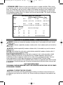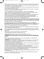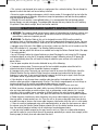
1
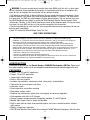
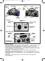
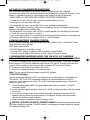
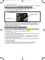
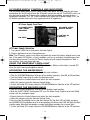
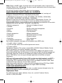
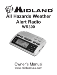
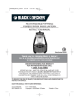
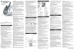
PS400JRB_Manual EN_090506 SE.qxp
9/6/06
3:38 PM
Page i
ELECTROMATE®
INSTRUCTION MANUAL
Catalog Number PS400JRB
Thank you for choosing Black & Decker!
Go to www.BlackandDecker.com/NewOwner
to register your new product
BEFORE RETURNING THIS PRODUCT
FOR ANY REASON PLEASE CALL
1-800-544-6986
BEFORE YOU CALL, HAVE THE CATALOG No, AND DATE CODE
AVAILABLE. IN MOST CASES, A BLACK & DECKER REPRESENTATIVE
CAN RESOLVE THE PROBLEM OVER THE PHONE. IF YOU HAVE A
SUGGESTION OR COMMENT, GIVE US A CALL. YOUR FEEDBACK IS
VITAL TO BLACK & DECKER.
TO REDUCE THE RISK OF INJURY, THE USER MUST READ AND
UNDERSTAND THE INSTRUCTION MANUAL
SAVE THIS MANUAL FOR FUTURE REFERENCE.
Cat. # PS400JRB
SEPTEMBER ‘06
Form # ITM90509558
Copyright © 2006 Black & Decker
Printed in China
PS400JRB_Manual EN_090506 SE.qxp
9/6/06
3:38 PM
Page 1
GENERAL SAFETY WARNINGS AND INSTRUCTIONS FOR ALL APPLIANCES
READ ALL INSTRUCTIONS
WARNING: Read all instructions before operating product. Failure to follow all instructions listed
below may result in electric shock, fire and/or serious injury.
• AVOID DANGEROUS ENVIRONMENTS Don’t use appliances in damp or wet locations. Don’t use
appliances in the rain.
• KEEP CHILDREN AWAY. All visitors should be kept at a distance from work area.
• STORE IDLE APPLIANCES INDOORS. When not in use, appliances should be stored indoors in dry,
and high or locked-up place – out of reach of children.
• DON’T FORCE APPLIANCE. It will do the job better and with less likelihood of a risk of injury at the
rate for which it was designed.
• USE RIGHT APPLIANCE. Do not use the appliance for any job except that for which it
is intended.
• DRESS PROPERLY. Do not wear loose clothing or jewelry. They can be caught in moving parts.
Rubber gloves and substantial, non-skid footwear are recommended when working outdoors. Wear
protective hair covering to contain long hair.
• USE SAFETY GLASSES AND OTHER SAFETY EQUIPMENT. Use safety goggles or safety glasses with
side shields, complying with applicable safety standards and, when needed, a face shield. Also use face
or dust mask if operation is dusty. This applies to all persons in the work area. Also use a hard hat,
hearing protection, gloves, safety shoes and dust collection systems when specified or required. Safety
glasses or the like are available at extra cost at your local dealer or Black & Decker Service Center.
• DON’T ABUSE CORD. Never carry appliance by cord or yank it to disconnect from receptacle. Keep
cord from heat, oil, and sharp edges.
• DON’T OVERREACH. Keep proper footing and balance at all times.
• DISCONNECT APPLIANCES. Disconnect the appliance from the power supply when not in use, before
servicing, and when changing accessories such as blades and the like.
• AVOID UNINTENTIONAL STARTING. Don’t carry plugged-in appliance with finger on switch. Be sure
switch is off when plugging in.
• GROUND FAULT CIRCUIT INTERRUPTER (GFCI) protection should be provided on the circuits or
outlets to be used. Receptacles are available having built in GFCI protection and may be used for this
measure of safety.
• USE OF ACCESSORIES AND ATTACHMENTS. The use of any accessory or
attachment not recommended for use with this appliance could be hazardous. Note: Refer to the
accessory section of this manual for further details.
• STAY ALERT. Watch what you are doing. Use common sense. Do not operate tool when you are tired.
• CHECK DAMAGED PARTS. Before further use of the tool, a guard or other part that is damaged should
be carefully checked to determine that it will operate properly and perform its intended function. Check
for alignment of moving parts, binding of moving parts, breakage of parts, mounting, and any other
conditions that may affect its operation. A guard or other part that is damaged should be properly
repaired or replaced by an authorized service center unless otherwise indicated elsewhere in this
instruction manual. Have defective switches replaced by authorized service center. Do not use tool if
switch does not turn it on and off.
• DO NOT OPERATE portable electric tools near flammable liquids or in gaseous or explosive
atmospheres. Motors in these tools normally spark, and the sparks might ignite fumes.
• OUTDOOR USE EXTENSION CORDS. When tool is used outdoors, use only extension
cords intended for use outdoors and so marked.
1
PS400JRB_Manual EN_090506 SE.qxp
9/6/06
3:38 PM
Page 2
• EXTENSION CORDS. Make sure your extension cord is in good condition. When using
an extension cord, be sure to use one heavy enough to carry the current your product will
draw. An undersized cord will cause a drop in line voltage resulting in loss of power and
overheating. The following table shows the correct size to use depending on cord length
and nameplate ampere rating. If in doubt, use the next heavier gage. The smaller the gage
number, the heavier the cord.
Volts
Minimum Gage for Cord Sets
Total Length of Cord in Feet
120V
0-25
26-50
51-100
101-150
(15,2-30,4m)
(30,4-45,7m)
0-50
51-100
101-200
(0-15,2m) (15,2-30,4m) (30,4-60,9m)
201-300
(60,9-91,4m)
(0-7,6m) (7,6-15,2m)
240V
Ampere Rating
More
Than
0 6 10 12 -
Not more
Than
6
10
12
16
American Wire Gage
18
18
16
14
16
16
16
12
16
14
14
12
14
12
Not Recommended
SAFETY GUIDELINES / DEFINITIONS
DANGER: Indicates an imminently hazardous situation which, if not avoided, will result in death
or serious injury.
WARNING: Indicates a potentially hazardous situation which, if not avoided, could result in death or
serious injury.
CAUTION: Indicates a potentially hazardous situation which, if not avoided, may result in minor or
moderate injury.
CAUTION: Used without the safety alert symbol indicates potentially hazardous situation which, if
not avoided, may result in property damage.
RISK OF UNSAFE OPERATION. When using tools or equipment, basic safety precautions should
always be followed to reduce the risk of personal injury. Improper operation, maintenance or
modification of tools or equipment could result in serious injury and property damage. There are
certain applications for which tools and equipment are designed. Black & Decker strongly
recommends that this product NOT be modified and/or used for any application other than for which
it was designed. Read and understand all warnings and operating instructions before using any tool
or equipment.
SAVE THESE INSTRUCTIONS
THIS MANUAL CONTAINS IMPORTANT SAFETY AND OPERATING INSTRUCTIONS FOR THE POWER
STATION MODEL PS400JRB.
WARNING: TO REDUCE THE RISK OF INJURY:
• Follow these instructions and those published by the battery manufacturer and manufacturer of
any equipment you intend to use with this unit. Review cautionary markings on these products and
on engine.
2
PS400JRB_Manual EN_090506 SE.qxp
9/6/06
3:38 PM
Page 3
IMPORTANT SAFETY INSTRUCTIONS
WARNING: This product or its power cord contains lead, a chemical known to the State of California to
cause cancer and birth defect or other reproductive harm. Wash hands after handling.
WARNING: BURST HAZARD: Do not use the unit for charging dry-cell batteries that are commonly
used with home appliances. These batteries may burst and cause injury to persons and damage property.
Use the unit for charging/boosting a LEAD-ACID battery only. It is not intended to supply power to a lowvoltage electrical system other than in a starter-motor application.
WARNING: SHOCK HAZARD:
• If an extension cord is used, make sure that:
a) the pins of extension cord are the same number, size and shape as those in the power station,
b) the extension cord is properly wired and in good electrical condition,
c) the wire size is large enough for the AC rating of the charger as indicated in the table on page 2.
• Do not operate unit with damaged cord or plug; or if the unit has received a sharp blow, been dropped, or
otherwise damaged in any way. Do not disassemble the unit; take it to a qualified service technician when
service or repair is required. Incorrect reassembly may result in a risk of electric shock or fire, and will
void warranty.
• Use of an attachment not supplied, recommended or sold by manufacturer specifically for use with this
unit may result in a risk of electrical shock and injury to persons.
• NEVER submerge this unit in water; do not expose it to rain, snow or use when wet.
• To reduce risk of electric shock, disconnect the unit from any power source before attempting
maintenance or cleaning. Turning off controls without disconnecting will not reduce this risk.
WARNING: RISK OF EXPLOSIVE GASES
• Working in the vicinity of a lead acid battery is dangerous. Batteries generate explosive gases during
normal battery operation. For this reason, it is of the utmost importance that each time before using the
power station you read this manual and follow instructions exactly.
• To reduce the risk of battery explosion, follow these instructions and those published by the battery
manufacturer and manufacturer of any equipment you intend to use in the vicinity of the battery. Review
cautionary markings on these products and on the engine.
• This equipment employs parts (switches, relays, etc.) that produce arcs or sparks. Therefore, if used in a
garage or enclosed area, the unit MUST be placed not less than 18 inches above the floor.
• THIS UNIT IS NOT FOR USE BY CHILDREN AND SHOULD ONLY BE OPERATED BY ADULTS.
CAUTION: TO REDUCE THE RISK OF INJURY OR PROPERTY DAMAGE:
• Pull cord by plug rather than cord when disconnecting the 120V AC Charging Adapter from the unit.
• NEVER ATTEMPT TO JUMP-START OR CHARGE A FROZEN BATTERY.
• To recharge this unit, use only the supplied AC Charging Adapter.
• Vehicles that have on-board computerized systems may be damaged if vehicle battery is jump-started.
Before jump-starting, read the vehicle’s owner’s manual to confirm that external-starting assistance
is suitable.
• When working with lead acid batteries, always make sure immediate assistance is available in case
of accident or emergency.
• Always have protective eyewear when using this product: contact with battery acid may cause
blindness and/or severe burns. Be aware of first aid procedures in case of accidental contact with
battery acid.
• Have plenty of fresh water and soap nearby in case battery acid contacts skin.
• If battery acid contacts skin or clothing, wash immediately with soap and water for at least 10
minutes and get medical attention immediately.
• Never smoke or allow a spark or flame in vicinity of vehicle battery, engine or power station
3
PS400JRB_Manual EN_090506 SE.qxp
9/6/06
3:38 PM
Page 4
• Remove personal metal items such as rings, bracelets, necklaces and watches when working with
a lead acid battery. A lead acid battery can produce a short circuit current high enough to weld a
ring, or the like of a metal, causing a severe burn.
• Do not wear vinyl clothing when jump-starting a vehicle when jump-starting a vehicle, friction can
cause dangerous static-electrical sparks.
• When connecting the battery clamps to a discharged battery and an alarm sounds — the clamp
connections are incorrect and need to be reversed.
• Jump-start procedures should only be performed in a safe, dry, well-ventilated area.
• Always store battery clamps detached from unit when not in use. Never touch battery clamps
together. This can cause dangerous sparks, power arcing and/or explosion.
• When using this unit close to the vehicle’s battery and engine, stand the unit on a flat, stable surface,
and be sure to keep all clamps, cords, clothing and body parts away from moving vehicle parts.
• Never allow red and black clamps to touch each other or another common metal conductor — this
could cause damage to the unit and/or create a sparking/explosion hazard.
a) For negative-grounded systems, connect the POSITIVE (RED) clamp to the POSITIVE ungrounded
battery post and the NEGATIVE (BLACK) clamp to the vehicle chassis or engine block away from the
battery. Do not connect the clamp to the carburetor, fuel lines or sheet-metal body parts. Connect to a
heavy gauge metal part of the frame or engine block.
b) For positive-grounded systems, connect the NEGATIVE (BLACK) clamp to the NEGATIVE
ungrounded battery post and the POSITIVE (RED) clamp to the vehicle chassis or engine block away
from the battery. Do not connect the clamp to the carburetor, fuel lines or sheet-metal body parts.
Connect to a heavy gauge metal part of the frame or engine block.
• Always disconnect the negative (Black) jumper cable first, followed by the positive (Red) jumper
cable, except for positive grounded systems.
• Do not expose battery to fire or intense heat since it may explode. Before disposing of the battery,
protect exposed terminals with heavy-duty electrical tape to prevent shorting (shorting can result in
injury or fire).
• Place this unit as far away from the battery as DC cables permit.
• Never allow battery acid to come in contact with this unit.
• Do not operate this unit in a closed area or restrict ventilation in any way.
• FIRST AID – SKIN: If battery acid comes in contact with skin, rinse immediately with water, then
wash thoroughly with soap and water. If redness, pain, or irritation occurs, seek immediate medical
attention.
EYES: If battery acid comes in contact with eyes, flush eyes immediately, for a minimum of 15
minutes and seek immediate medical attention.
• IMPORTANT: This unit is delivered in a partially charged state. Fully charge unit with a household
extension chord (not supplied) for a full 24 hours before using for the first time. You cannot
overcharge the unit using the AC charging method.
• Do not recharge for more than 5-6 hours maximum using the 12 volt DC method. Overcharging the
battery using this method will shorten the battery life.
• All On/Off switches should be in the OFF position when the unit is charging or not in use. Make sure
all switches are in the OFF position before connection to a power source or load.
• Never insert anything other than the supplied power/recharging cords or recommended appliance
power/recharging cords into the 12 volt DC charging/power outlet on this unit. Do not use any
accessory that is not recommended or provided by the manufacturer.
• Do not use this unit to operate appliances that need more than 5 amps to operate from the 12 volt
DC accessory outlet.
• This system is designed to be used only on vehicles with a 12 volt DC battery system. Do not
connect to a 6 volt or 24 volt battery system.
4
PS400JRB_Manual EN_090506 SE.qxp
9/6/06
3:38 PM
Page 5
• This system is not designed to be used as a replacement for a vehicular battery. Do not attempt to
operate a vehicle that does not have a battery installed.
• Excessive engine cranking can damage a vehicle’s starter motor. If the engine fails to start after the
recommended number of attempts, discontinue jump-start procedures and look for other problems
that may need to be corrected.
• Although this unit contains a non-spillable battery, it is recommended that unit be kept upright
during storage, use and recharging. To avoid possible damage that may shorten the unit’s working
life, protect it from direct sunlight, direct heat and/or moisture.
WEATHER RADIO SAFETY INSTRUCTIONS
WARNING: This product should not be the only source of information for all-hazard, watches and
warnings. If severe weather is imminent; do not wait to receive the weather alert warning, take
precautionary measures to protect yourself.
WARNING: The Weather Radio in this unit is designed to receive NOAA weather and other
emergency alerts as listed on page 12 of this manual and communicate these alerts to you. You may
not receive or clearly hear these alerts under any of, but not limited to, the following circumstances:
• Improper setup (Unit not in Alert Mode, or turned on); make sure that the unit is turned on and the
Alert LED indicator is lit, (see page 11 for Weather Radio instruction).
• Volume is too low; adjust the volume to an audible level using the Volume Control Knob. (See page
7 for radio controls)
• Loss of AC power and/or the internal batteries are dead. Recharge the unit using the DC charging
method on page 8 or using the AC charging method on page 8 following return of AC power. Be
sure to occasionally place the unit back on charge to maximize your runtime in the event of AC
power failure.
• Lost or poor reception which can be attributed to any of the following:
a) Improper antenna setup. To ensure you get the best available reception extend the built-in
antenna and adjust its direction to provide maximum reception.
b) Improper tuner setup. To ensure you are always tuned in to receive the NOAA alerts check the
National Weather Service website @ http://www.nws.noaa.gov/nwr/nwrbro.htm for the signal
frequency in your area. If you are on the correct frequency and fail to get a signal, check that you
have power and/or try placing the radio close to a window.
c) Your location is out of range from a weather radio transmitter; the broadcast range from the
weather radio transmitter is approximately 40 miles. The effective range depends on such things as
terrain and quality of the receiver and indoor/outdoor antenna. Log onto
http://www.nws.noaa.gov/nwr/nwrbro.htm to see which frequency best serves your area.
d) Metal structure; to improve the radio’s ability to receive NOAA broadcast; do not place the unit
near any large obstructions or metal surfaces such as refrigerators, metal cabinets, etc. In metal
structures, such as mobile homes, reception is difficult because the metal structure impedes the
transmission of monitor waves, in this case, place the radio close to a window to improve reception.
e) Radio frequency interference; some electronics may cause radio frequency interference such as
two-way radios, remote control cars, etc. Place the unit as far away as possible from these devices
or avoid the usage of devices that cause radio frequency interference while the unit is in alert mode.
• If there is excessive background noise while monitoring alerts; or when the alert comes on, adjust
the volume using the Volume Control Knob or relocate the unit to a better location where you can
hear the weather broadcast without risk of interference from background noise.
• If you are out of audible range of or far away from the unit; or if there is an obstruction between
you and the radio, be sure to check the unit for warnings periodically or remain close enough (within
hearing range) to clearly hear and understand the alerts.
5
PS400JRB_Manual EN_090506 SE.qxp
9/6/06
3:38 PM
Page 6
WARNING: To ensure to continuously monitor alerts from NOAA while the unit is in alert mode,
the unit should be checked periodically to confirm its functionality and for loss of reception; also
check for loss of reception after moving the unit to a different location.
• Test Warnings from NOAA; all National Weather Services periodically transmit test signals. Some
stations broadcast a test signal every week on Wednesday between 11 AM and 1 PM, while others
test more often, the NWS may also broadcast System demonstrations. You can find out when your
local NWS broadcasts test signals by calling the NOAA National Weather Service Forecast Office
(listed under “Weather” in the Federal Government section of the telephone book.) During the weekly
test signal, the local NWS will give a list of counties covered by their transmitter.
• Check unit periodically for wear and tear. Take to a qualified technician for replacement of worn or
defective parts immediately.
• Read This Instruction Manual Before Using This Unit.
SAVE THESE INSTRUCTIONS
This device complies with part 15 of the FCC rules. Operation is subject to the following two
conditions: (1) This device may not cause harmful interference, and (2) This device must accept any
interference received, including interference that may cause undesired operation.
This equipment has been tested and found to comply with the limits for a Class B digital device,
pursuant to part 15 of the FCC Rules, These limits are designed to provide reasonable protection
against harmful interference to radio communications. However, there is not guarantee that interference
to radio or television reception, with can be determined by turning the equipment off and on, user is
encouraged to try to connect the interference by one or more of the following measures:
• Reorient or relocate the receiving antenna.
• Increase the separation between equipment and receiver.
• Connect equipment into an outlet on a circuit different from that to which the receiver is connected.
• Consult the dealer or an experienced radio/TV technician for help.
INTRODUCTION
Thank you for purchasing the Black & Decker® PS400JRB Electromate® 400 Plus. Please read
this guide carefully before use to ensure optimum performance and avoid damage to the unit.
FEATURES
• Powers 110/120 volt AC appliances
• Powers 12 volt DC appliances
• Jump-starts vehicle engines
• Built-in 400 watt inverter
• Includes non-spillable, maintenance-free, heavy-duty, sealed battery
• Convenient to use, transport and store
• Alternator check
• Reverse polarity connection warning
• Detachable jumper cables
• Requires no maintenance (other than recharging) for optimum operation
• Rechargeable with built-in AC charger
• Unique compact design provides completely portable 12 volt DC power
• Molded high-impact case is tough and durable
• Built-in area light for night time roadside repairs and use in remote locations without
utility power
• Battery charge level indicators
• AM, FM and Weather Band radio with automatic NOAA Weather/Emergency Alert System
6
PS400JRB_Manual EN_090506 SE.qxp
9/6/06
3:38 PM
Back View
Front View
UNIT FRONT
PANEL
Page 7
RUBBER HANDLE
ANTENNA
AC CHARGER
JUMPER CABLE
CONNECTOR
RADIO
CONTROL
PANEL
USB PORT
DC POWER SUPPLY
PANEL
AIR VENT
AC POWER
SUPPLY PANEL
Front Panel
ALTERNATOR CHECK
INDICATOR
SPEAKER
REVERSE POLARITY
INDICATOR
BATTERY CHARGE LEVEL
INDICATORS
ON/OFF SWITCH
AREA LIGHT ON/OFF
PUSHBUTTON
Radio Control Panel
EARPHONE
CONNECTOR
ALERT ON/OFF
PUSHBUTTON
VOLUME
CONTROL
KNOB
RADIO
TUNER
KNOB
ALERT LOCK
ON/OFF
PUSHBUTTON
RADIO BAND SELECTOR
(OFF/AM/FM/WEATHER)
Protective Features
• Automatic Overload — Built-in protection against overload — in the event the AC outlet
draws more than 400 watts, power to the unit’s outlet will automatically shut off.
• Ground Fault Circuit Interrupter (GFCI) — The GFCI protects the unit and the user by
sensing imbalances in a circuit caused by current leakage to the ground and shuts down
the unit’s AC outlet to prevent electrical shock.
• Overheating — Unit automatically shuts down if it exceeds a safe temperature.
• Power Switch and Reverse Polarity Alarm — In event the cables/clamps are reversed
during jump-starting, an indicator lights and an alarm sounds BEFORE the Power Switch
is turned ON.
• Low Battery — If the battery power level is too low, the AC Power Supply shuts
down automatically.
7
PS400JRB_Manual EN_090506 SE.qxp
9/6/06
3:38 PM
Page 8
AC AND DC CHARGING/RECHARGING
Use a common household AC extension cord for charging (cord not supplied).
For maximum battery life, we recommend the unit be kept fully charged at all times. If the
battery is allowed to remain in a discharged state, battery life will be shortened.
• MAKE SURE ALL SWITCHES ARE TURNED OFF DURING RECHARGING.
• Charge the unit for a full 24 hours using AC method before first use.
• Recharge the unit fully after each use.
• Recharge the unit every two months when it has not been used regularly.
Notes: Recharging the battery after each use prolongs battery life; frequent discharges
between recharges reduces battery life.
The Electromate® also comes with a DC/DC charging adapter for recharging the unit from
a 12 volt DC accessory outlet in a vehicle.
If unit is fully discharged, it is recommended that the vehicle being used for recharging be
left running while the unit is charged via the 12 volt DC method.
VIEWING BATTERY CHARGE STATUS
Press the Battery Charge Level pushbutton to display battery status. The Battery Charge
Level Indicator LEDS will light.
LEDS (from right to left):
• Red LED indicates a low battery charge
• Two Red LEDs indicate a medium level or partially charged battery
• Two Red and one Green LED indicates a full or high level battery charge.
CHARGING/RECHARGING USING THE 120 VOLT AC CHARGER
AND A STANDARD HOUSEHOLD EXTENSION CORD (NOT INCLUDED)
1. Lift the AC Charger cover located on the back of the Electromate® and plug a standard
North American 120 volt AC extension cord into the 120 Volt AC Charger on the back of
the unit. Plug the other end of the cord into a standard 120 volt AC wall outlet.
2. Charge until two Red and one Green LEDs light.
3. Once fully charged, disconnect the extension cord.
Note: The unit cannot be overcharged using the AC method.
12 Volt DC Charging
The DC recharging method will NOT recharge the unit as effectively as recharging from
120 volt AC. The 12 volt DC recharging procedure is recommended only when it is
necessary, since frequent use of the 12 volt DC recharging procedure may shorten the
battery system’s life.
1. Insert the gold-tipped DC/DC charging adapter plug into the vehicle’s 12 volt DC
accessory outlet.
2. Insert the silver-tipped end plug into the 12 volt DC accessory outlet on the front panel
of the unit.
3. To check the charge status of the battery during DC charging, disconnect the DC
adapter from the accessory outlet and push the Battery Charge Level pushbutton.
Observe the battery charge indicator.
4. When charging is complete, remove the power cord.
CAUTION: TO REDUCE THE RISK OF PROPERTY DAMAGE: Do not recharge for more than 5
to 6 hours maximum using the 12 volt DC method. Overcharging the battery using this method
will shorten the battery life.
8
PS400JRB_Manual EN_090506 SE.qxp
9/6/06
3:38 PM
Page 9
USING THE ELECTROMATE® AS A JUMP-STARTER
WARNING: Before using this system to jump-start any vehicle read and understand all
instructions, safety tips, warnings, cautions and first aid information provided in this
manual and on the product labeling. Additional important information may also be
provided by the vehicle’s battery system manufacturer.
CAUTION: To avoid possible damage that may shorten the unit’s working life, protect this
unit from direct sunlight, direct heat and moisture.This system is to be used ONLY on
vehicles, garden tractors and gasoline-powered generators with 12 volt DC battery systems.
This system is NOT designed to be installed as a replacement for a vehicle battery.
• ONLY connect or disconnect battery leads when AC or DC charging supply cord
is disconnected.
JUMP-STARTING INSTRUCTIONS
This jump-starter is equipped with a manual switch that only allows jump-start energy to
flow when proper connections are made to battery and frame.
Connect — Red clamp first, then black clamp. Disconnect — Black clamp first, then red clamp.
1. Turn OFF vehicle ignition and all accessories (radio, A/C, lights, cell phone, etc.). Place
vehicle in “park” and set the emergency brake.
2. Make sure jump-start system’s ON/OFF power switch is turned to OFF.
3. Connect jumper cables to unit.
4. To jump-start a NEGATIVE GROUNDED SYSTEM (NEGATIVE battery terminal
is connected to the chassis — the most common configuration), follow steps 4a and 4b,
then proceed to step 6.
4a. Connect the positive (+) red clamp to vehicle battery’s positive ungrounded post.
4b. Connect the negative (–) black clamp to the vehicle chassis or engine block
away from the battery. Do not connect the clip to carburetor, fuel lines or
sheet-metal body parts. Connect to a heavy gauge metal part of the frame or
engine block.
5. To jump-start a POSITIVE GROUNDED SYSTEM — In the rare event that the vehicle to
be started has a Positive Grounded System, positive battery terminal is connected to
chassis, replace steps 4a and 4b above with steps 5a and 5b, then proceed to step 6.
5a. Connect negative (–) black clamp to vehicle battery’s negative ungrounded post.
5b. Connect positive (+) red clamp to the vehicle chassis or engine block away
from the battery. Do not connect the clip to carburetor, fuel lines or sheetmetal body parts. Connect to a heavy gauge metal part of the frame or
engine block.
DO NOT TURN POWER SWITCH ON IF REVERSE POLARITY ALARM SOUNDS OR THE
REVERSE POLARITY INDICATOR LIGHTS. REVERSE THE CLAMP CONNECTIONS.
6. After making proper connections, turn power switch to ON.
7. Start vehicle (do not turn key for longer than 5-6 seconds).
8. After vehicle starts, turn the power switch to off, remove clamps (disconnect the frame
or engine clamp first, followed by the battery cable). Disconnect the cables from unit.
USING THE ALTERNATOR CHECK FEATURE
1. Turn the power switch to the off position.
2. Connect jumper cables to unit.
3. Connect to vehicle.
4. Start engine.
9
PS400JRB_Manual EN_090506 SE.qxp
9/6/06
3:38 PM
Page 10
5. Turn vehicle accessories off.
6. A solid green LED indicates a good alternator. A solid red LED indicates a bad alternator.
USING THE 12 VOLT DC PORTABLE POWER SUPPLY
1. Flip open one of the 12 volt DC outlet covers on the DC Power Supply Panel.
2. Insert the 12 volt DC plug from the appliance into the outlet.
3. Turn on the appliance and operate normally.
DC Power Supply Panel
12 VOLT DC OUTLETS
AIR VENTS
NOTE: The 12 volt DC accessory outlets on the unit are protected by a 5 Amp manual
resetting breaker that will trip in the event of overload. Simply unplug the appliance to reset
the breaker. To avoid tripping this breaker, DO NOT USE UNIT TO POWER APPLIANCES
THAT DRAW MORE THAN 5 AMPS DC.
USING THE 120 VOLT AC POWER SUPPLY
The 120 Volt AC Power Supply is designed for maintaining today's modern lifestyle while
traveling in vans, RVs, automobiles, trucks, or vehicles that have a 12 volt DC battery
power supply and a means to recharge those batteries. The Electromate® 400 Plus comes with:
1. AC On/Off Switch — to turn the AC Power Supply on and off.
2. 120 Volt AC Power Outlets
3. AC Power Supply “ON” Status Indicator — green LED lights when AC outlet is turned
on; green LED flashes on and off when faulted.
4. AC Power Ground Fault Circuit Interrupt (GFCI) — a 3-prong outlet for 120 volt AC
appliances which shuts down inverter if leakage or ground fault current is detected.
5. Internal protective circuits including:
• Overload and over-temperature shutdown (activated if AC output exceeds 400 watts)
• AC short-circuit shutdown
• Low voltage shutdown
• A new cooling technology that more efficiently cools the power transistors and,
combined with soft start, dramatically increases reliability and product life
10
PS400JRB_Manual EN_090506 SE.qxp
9/6/06
3:38 PM
Page 11
AC POWER SUPPLY CONTROLS AND INDICATORS
The illustration below details the AC Power Supply front panel. Air vents keep the unit from
overheating. An On/Off switch turns the AC power circuitry on and off. The ON/OFF switch can
also be used to reset the AC power after shutdown due to overvoltage, overload or overtemperature condition. The “On” status indicator lights when the AC power supply is on. The
AC outlets (covered when not in use) supply power to AC appliances.
AC Power Supply Front Panel
AC POWER SUPPLY
“ON” STATUS
INDICATOR
AC POWER SUPPLY
ON/OFF SWITCH
120 VOLT AC
OUTLETS
AIR VENTS
AC Power Supply Operation
1. Turn power switch to on (the power indicator lights).
2. Plug in appliance and turn the appliance on.
Note: The AC power supply shuts down automatically when the battery voltage level is too
low. If the green LED flashes, a faulty condition such as an overload, overheating or short
circuiting has occurred. Turn the AC Power Supply off and unplug the appliance. Wait a
few minutes, then turn power back on.
USING THE EMERGENCY AREA LIGHT
The Area Light is controlled by an ON/OFF pushbutton. Make sure the light is turned OFF
when the unit is being recharged or stored.
OPERATING THE AM/FM RADIO
See page 6 to locate referenced controls, knobs and selectors.
• Slide the OFF/AM/FM/Weather Selector to the desired frequency (the AM or FM position).
• Turn the Radio Tuner Knob to select the desired station.
• Extend the built-in Radio Antenna and adjust for best reception.
• Adjust the volume using the Volume Control Knob.
• To turn the Radio OFF, simply slide the OFF/AM/FM/Weather Selector to the OFF position.
OPERATING THE WEATHER RADIO
• Slide the OFF/AM/FM/Weather Selector to the Weather band position.
• With the ALERT ON/OFF Pushbutton OFF, turn the Radio Tuner Knob to select the NOAA
station with the strongest signal.
• Extend the built-in Radio Antenna and adjust for best reception.
• Adjust the volume using the Volume Control Knob.
• Press the Alert Pushbutton to turn the Alert feature ON (the Alert LED will light) and press
the ALARM/LOCK Pushbutton to set it in lock position (the Alarm Lock LED will light) for Alert
standby mode. Note that the speaker is muted while Radio monitors for a hazard alert.
• To turn the Radio OFF, simply slide the OFF/AM/FM/Weather Selector to the OFF position.
11
PS400JRB_Manual EN_090506 SE.qxp
9/6/06
3:38 PM
Page 12
Notes: While in ALERT mode, the hazard alarm will sound briefly when a hazard alert is
received. While in the LOCK position, the alarm sounds continuously when the hazard alert
is received until the user turns it off.
For the Lock Function to be available, Alert must be engaged.
NOAA WEATHER RADIO (NWR) ALL HAZARDS
NWR is an all-hazards public warning system, broadcasting forecast, warning and
emergency information 24 hours a day directly to the public.
7 NWR Broadcast Frequencies include: 162.400MHz, 162.425 MHz, 162.450 MHz,
162.475 MHz, 162.500 MHz, 162.525 MHz, 162.550MHz
Broadcast range from the weather radio transmitter is approximately 40 miles. The
effective range depends on such things as terrain and quality of the receiver and
indoor/outdoor antenna. Log onto http://www.nws.noaa.gov/nwr/nwrbro.htm to see which
frequency best serves your area. “All-Hazard” messages are:
• Weather emergencies
• Chemical & biological hazard
• Tornados
• Oil spill
• Hurricanes
• Nuclear power plant emergencies
• Floods
• Maritime accidents
• Blizzards
• Train derailment
• Natural emergencies
• National emergencies
• Earthquakes
• Homeland security warnings
• Forest fires
• Terrorists attacks
• Avalanches
• Civil emergencies
• Technological emergencies
• Amber alerts
Non-weather emergency messages will be broadcast over NWR when:
• (1) public safety is involved
• (2) the message comes from an official government source
• (3) time is critical
The National Response Plan assigns responsibility to NOAA’s National Weather Service
(NWS) to broadcast non-weather emergency messages.
Non-weather emergency messages will be broadcast over NWR at the request of local
and/or state officials who wish to broadcast a message on NWR, the official provides text
information about the hazard and the appropriate response directly to the local NWS
offices. NWS offices have set up pre-arranged agreements to facilitate and speed
the process.
NWR and the Emergency Alert System (EAS) use the same digital protocols, and NWR is
the primary means for NWS alerts to activate the EAS. The Federal Communications
Commission (FCC) amended the EAS rules in 2002 and adopted numerous codes. NWS
introduced the new codes on June 30, 2004. Log onto
https://www.weather.gov/os/eas_codes.shtml for a complete listing of EAS Event (NWRSAME) Codes if your receiver is equipped with Digital SAME Technology.
CARE AND MAINTENANCE
WARNING: RISK OF FIRE: If the cord, wires, or cables become damaged, return the
entire unit to Black & Decker immediately for service/repair.
Replacement Parts
For replacement parts (bulbs, batteries, fuses, etc.), contact Customer Service,
toll-free, at (800) 544-6986.
12
PS400JRB_Manual EN_090506 SE.qxp
9/6/06
3:38 PM
Page 13
Battery Replacement/Disposal
It is recommended that the unit be returned to Customer Service for
battery replacement.
This unit contains a maintenance-free, non-spillable, sealed lead-acid
battery. This battery is fully recyclable and should be accepted at any
location that accepts common automotive starter batteries. Examples of
places that accept these batteries are: county or municipal recycling
drop-off centers, scrap metal dealers and retailers who sell automotive replacement lead acid
starter batteries. For more information, call 1-877-288-7722.
WARNINGS: Do not dispose of the battery in fire, as this may result in an explosion.
Before disposing of the battery, protect exposed terminals with heavy-duty electrical tape
to prevent shorting (shorting can result in injury or fire).
Do not expose battery to fire or intense heat, as it may explode.
Fuse Replacement (DC Accessory Adapter)
1. Remove plug from accessory outlet. Remove the gold cap by turning counterclockwise
and lifting off.
2. Remove center pin and spring. Remove fuse.
3. Replace fuse with same type and size fuse (8 amp).
4. Replace center pin and spring inside plug.
5. Replace gold cap by turning clockwise.
For assistance with your product, visit our website www.blackanddecker.com for the
location of the service center nearest you or call the BLACK & DECKER help line
at 1-800-544-6986.
Accessories
Recommended accessories for use with your tool are available from your local dealer or
authorized service center. If you need assistance regarding accessories, please
call: 1-800-544-6986.
WARNING: The use of any accessory not recommended for use with this tool could
be hazardous.
SERVICE INFORMATION
All Black & Decker Service Centers are staffed with trained personnel to provide
customers with efficient and reliable power tool service. Whether you need technical
advice, repair, or genuine factory replacement parts, contact the Black & Decker location
nearest you. To find your local service location, refer to the yellow page directory under
"Tools—Electric" or call: 1-800-544-6986 or visit www.blackanddecker.com
FULL TWO-YEAR HOME USE WARRANTY
Black & Decker (U.S.) Inc. warrants this product for two years against any defects in
material or workmanship. The defective product will be replaced or repaired at no charge
in either of two ways.
The first, which will result in exchanges only, is to return the product to the retailer from
whom it was purchased (provided that the store is a participating retailer). Returns should
be made within the time period of the retailer’s policy for exchanges (usually 30 to 90 days
after the sale). Proof of purchase may be required. Please check with the retailer for their
specific return policy regarding returns that are beyond the time set for exchanges.
The second option is to take or send the product (prepaid) to a Black & Decker owned or
authorized Service Center for repair or replacement at our option. Proof of purchase may be
required. Black & Decker owned and authorized Service Centers are listed under "Tools-Electric"
13
PS400JRB_Manual EN_090506 SE.qxp
9/6/06
3:38 PM
Page 14
in the yellow pages of the phone directory and on our website www.blackanddecker.com.
This warranty does not apply to accessories. This warranty gives you specific legal rights
and you may have other rights which vary from state to state or province to province.
Should you have any questions, contact the manager of your nearest Black & Decker
Service Center. This product is not intended for commercial use.
FREE WARNING LABEL REPLACEMENT: If your warning labels become illegible or are
missing, call 1-800-544-6986 for a free replacement.
SPECIFICATIONS
12 Volt DC Specifications
Battery:
Internal Battery Type:
Internal Battery Capacity:
Area Light :
Jumper Cables:
Accessory Outlet Protection:
DC Charging Adapter:
12 volt DC rechargeable, maintenance-free
Sealed, AGM lead-acid
12 volt 19Ah/20 hour rate
Light Emitting Diode (LED)
Heavy duty welding cable with 450 amp clamps
5 amp, dual self-resetting breakers
12 volt DC
AC Power Specifications
Output Power:
Output Voltage:
Output Frequency:
Output Waveform:
Overheat Protection:
Overload Protection:
Output Short Circuit Protection:
Continuous — 400 watts
120 VAC RMS
60 Hz ±4 Hz
Modified sine wave
Yes
Yes
Yes
Battery Charger Specifications
Input:
Rapid Charging Current:
120 V AC, 60 Hz
12 V DC 1000 mA
Radio Specifications
Radio Stations:
Weather Radio Sensitivity:
Speaker:
AM: 530-1710 kHz
FM: 88-108 MHz
Weather: 162.400, 162.425, 162.450,
162.475, 162.500, 162.525, and 162.550 MHz
0.6µV@12dB SINAD
0.5µV@1050 Hz alert tone
8 ohm, 3 W
Imported by
Black & Decker (U.S.) Inc.,
701 E. Joppa Rd.
Towson, MD 21286 U.S.A.
Vector Products, Inc
4140 SW 30th Ave.
Fort Lauderdale, FL 33312
14
PS400JRB_Manual EN_090506 SE.qxp
9/6/06
15
3:38 PM
Page 15
PS400JRB_Manual EN_090506 SE.qxp
9/6/06
16
3:38 PM
Page 16
PS400JRB_Manual EN_090506 SE.qxp
9/6/06
17
3:38 PM
Page 17