1
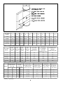
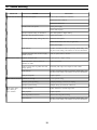
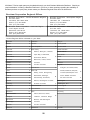
Price - $3.00
INSTALLATION, OPERATING
AND
SERVICE INSTRUCTIONS
ALLIANCETM SERIES
INDIRECT-FIRED WATER HEATERS
MODELS AL-26A, 40A, 53A, 79A and 119A
for SINGLE WATER
HEATER
INSTALLATIONS
For service or repairs to the water heater, call your heating contractor. When seeking information on water
heater, provide Model Number and Serial Number as shown on Rating Label.
Model Number
_ AL _______
Serial Number
Installation Date
_____
Heating Contractor
Phone Number
Address
®
AMERICA’S BOILER COMPANY
8140817R3-3/00
Burnham
Corporation
1
Lancaster, PA 17604-3079
IMPORTANT INFORMATION - READ CAREFULLY
NOTE: The equipment shall be installed in accordance with those installation regulations required in the area where the
installation is to be made. These regulations shall be carefully followed in all cases. Authorities having jurisdiction
shall be consulted before installations are made.
All wiring on water heaters installed in the USA shall be in accordance with the National Electrical Code and/or local
regulations.
All wiring on water heaters installed in Canada shall be in accordance with the Canadian Electrical Code and/or local
regulations.
The following defined terms are used throughout this manual to bring attention to the presence of hazards of various risk levels,
or to important information concerning the life of the water heater.
CAUTION
DANGER
Ind ica tes a po ten tia lly h aza rdo us situa tio n
which, if n ot av oid ed, m ay result in
mo derate o r m ino r injury o r p rop erty
dam age .
Indicates an imminently haz ardous situation
wh ic h, if n ot a voi de d, will re sul t in de at h,
serious injury or substantial property damage.
N O T IC E
WARNING
Indicates spec ial ins tru ctions on
ins tallatio n, ope ra tion, or maintenanc e
which are importan t but not re late d to
persona l injury ha zards .
In dic at es a pot ent ia lly ha za rdo us s itu ation
which, if not avoide d, could result in death,
serious injury or substantial property damage.
DANGER
DO NOT store or use gasoline or other flammable vapors or liquids in the vicinity of this or any
other appliance.
If you smell gas vapors, DO NOT try to operate any appliance - DO NOT touch any electrical
switch or use any phone in the building. Immediately, call the gas supplier from a remotely
located phone. Follow the gas supplier's instructions or if the supplier is unavailable, contact the
fire department.
2
I. General Information
WARNING
Improper installation, adjustment, alteration, service or maintenance can cause property
damage, personal injury or loss of life. Read and understand the entire manual before
attempting installation, start-up operation, or service. Installation and service must be
performed only by an experienced, skilled installer or service agency.
Installation is not complete unless a pressure and temperature relief valve is installed into
the side of the water heater. See Piping Section of this manual for details.
This water heater contains very hot water under high pressure. Do not unscrew any pipe
fittings nor attempt to disconnect any components of this water heater without positively
assuring the water is cool and has no pressure. Always wear protective clothing and
equipment when installing, starting up or servicing this water heater to prevent scald
injuries. Do not rely on the pressure and temperature gauges to determine the temperature
and pressure of the water heater. This water heater contains components which become
very hot when the boiler is operating. Do not touch any components unless they are cool.
Water heater materials of construction contain urethane, heavy metals and/or other toxic or
harmful substances which can cause death or serious injury and which are known to the
state of California to cause cancer, birth defects and other reproductive harm. Always use
proper safety clothing, respirators and equipment when servicing or working nearby this
water heater.
Failure to follow all instructions in the proper order can cause personal injury or death.
Read all instructions, including all those contained in component manufacturers' manuals
which are provided with the water heater before installing, starting up, operating, maintaining
or servicing.
NOTICE
The Alliance water heater must be installed with a pressure and temperature relief valve. The
valve is not supplied with the water heater and must be provided by the installer.
Table of Contents
Section I - General Information ............................ 3
Section V - Operation .......................................... 16
Ratings, Capacities, Weights, & Dimensions ....... 4
Section VI - Service Instructions ........................ 17
Section II - Pre-Installation ................................... 5
Section VII - Trouble Shooting ........................... 18
Section III - Piping ................................................ 8
Section VIII - Repair Parts .................................. 19
Section IV - Electrical ......................................... 15
Warranty .............................................. Back Cover
3
Table 1: Alliance Water Heater Dimension (Inches)
ALL IA NCE
MODEL
A
B
C
D
E
F
G
H
I
J
K
AL 26A
40
20-1/4
31-1/2
22-1/2
9-3/4
2
3/4
3/4
3/4
3/4
3/4
AL 40A
55
20-1/4
46-1/2
25-3/4
9-3/4
2
3/4
3/4
3/4
3/4
3/4
AL 53A
70-5/8
20-1/4
62-1/8
28-3/4
9-3/4
2
3/4
3/4
3/4
3/4
3/4
AL 79A
69-3/8
23-3/4
60-7/8
29-1/4
10-1/4
1-5/8
1
3/4
3/4
1
1
AL119A
66
29-1/2
52-3/4
39-1/4
12-3/4
2-1/2
1-1/4
1-1/4
1-1/4
1-1/4
1
Table 2: Alliance Water Heater Capacities
ALLIANCE
MODEL
TANK
VOLUME
(GAL)
COIL
VOLUME
(GAL)
DRY
WEIGHT
(LB S)
WET
WEIGHT
(LB S)
COIL HEAT
TRANSFER
AREA ( SQ. FT.)
M AXIMUM
ALLOWA BLE
WORKING
P RESSURE (PSI)
HYDROSTATIC
DESIGN
P RESSURE (PSI)
AL 26A
26.4
1.0
49
269
6.5
150
300
AL 40A
39.6
1.2
66
396
8.6
150
300
AL 53A
52.8
1.4
82
522
9.7
150
300
AL 79A
79.3
2.2
170
831
15.1
150
300
AL119A
119.4
2.9
183
1178
24.3
150
300
Table 3: Alliance Water Heater Performance
M A X IM U M FIR S T
HO UR RAT IN G
G A L/ HR @
CO NT IN UO U S
RAT IN G
G A L /M IN @
14 0 F
11 5 F
14 0 F
11 5 F
B O IL E R D O E
H E ATIN G C A PA CITY
N E E DE D FO R
R ATI NG S (B TU/ HR )
AL2 6A
1 42
1 97
1. 93
2. 84
11 0 ,0 00
8 .0
2 .5
2 .4
AL4 0A
1 75
2 42
2. 26
3. 38
13 3 ,0 00
11 .4
6 .1
7 .2
AL5 3A
2 24
3 10
2. 85
4. 29
16 4 ,0 00
10 .9
6 .5
9 .0
AL7 9A
2 53
3 50
2. 90
4. 51
19 0 ,0 00
10 .6
8 .4
9 .1
A L 11 9 A
3 50
4 09
3. 84
4. 83
38 6 ,0 00
15 .4
11 .6
16 .4
MO DE L
M I NI M UM B O I LE R
W ATE R F LO W
TH R O U G H HE ATE R
C O IL (G A L /M IN )
P R E S S UR E
D RO P TH RO U G H
C O I L AT M IN .
FL O W (F T. W .C .)
M IN UT ES O F
1 40 F W ATE R
AVA IL A B L E AT
5 G P M D RA W
N O T E S : A l l ra tin g s b a s e d o n 2 0 0 F b o ile r w a te r t e m p e ra t u re , 5 0 F d o m e s t ic w a te r in le t te m p e ra tu r e , a n d a f u lly re c o ve r e d
t a n k (w h e n a p p lic a b le ).
4
CAUTION
The heat transfer medium must be water or other non-toxic fluid having a toxicity rating or class
of 1, as listed in clinical Toxicology of Commercial Products, 5th edition.
The pressure of the heat transfer medium must be limited to a maximum of 30 psig by an
approved safety or relief valve.
NOTICE
This w ater heater has a limited warranty, a copy of w hich is printed on the back of this manual.
It is the responsibility of the installing contractor to see that all controls are correctly installed
and are operating properly when the installation is complete.
II. Pre-Installation
present.
Inspect shipment carefully for any sign of damage. All
equipment is carefully manufactured, inspected and
packed. Burnham Corporation's responsibility ceases
upon delivery of water heater to the carrier in good
condition. Any claim for damage or shortage in
shipment must be filed immediately against the carrier
by the consignee. No claims for variances or shortages
will be allowed by Manufacturer, unless presented
within sixty (60) days after receipt of equipment.
Consult Burnham for size recommendations for
installation with unusual water demand.
Refer to Table 3 for water heater performance
specifications.
2. Boiler DOE Heating Capacity The Alliance™
water heater will provide the rated performance
only if used in conjunction with a boiler with a
DOE heating capacity at least as much as the
minimum noted in Table 3. If the boiler has less
capacity, the output of the tank will be reduced. To
determine the approximate reduction in output from
the tank use the following formula:
Installation must conform to the requirements of the
authority having jurisdiction. In the absence of such
requirements, installation must conform to National
Plumbing Code and National Electrical Code,
ANSI/NFPA No. 70, current edition.
IMPORTANT DECISIONS REQUIRED BEFORE
INSTALLATION:
For example, what would the first hour rating be if
a model AL53A were installed with a boiler having
a DOE heating capacity of 120,000 BTU/h?
A. Sizing
Increasing the boiler DOE heating capacity above
the values listed in Table 3 will not increase the
rating of the water heater.
1. Alliance™ Model - Choose the Alliance™ model
based on the expected water usage of the building.
The average residence with one shower or more
will require a model AL40A or larger. The AL26A
should only be considered for residences with
minimal water demand or for commercial
application where showers are not present.
3. Circulator Sizing - Refer to Table 3 for the
minimum flow rate through the water heater coil
and the corresponding pressure drop through the
coil. Calculate the pressure drop of all straight pipe
and fittings on the supply and return of the water
heater at the minimum flow rate. Add the piping/
fitting pressure drop to the pressure drop through
the water heater coil.
Factors which dramatically increase water demand
include high flow shower heads, whirlpool tubs,
and the use of multiple showers at the same time.
Upsize the tank size if any of these factors are
5
during simultaneous space and domestic hot water
heating operations, depending on such factors as
boiler output, boiler over sizing, number of space
heating zones calling for heat and ratio of domestic
hot water load to space heating load.
Select a circulator which will provide at least the
minimum flow rate at combined pressure drop.
B. System Zone Control The AllianceTM water
heater must be installed as a zone separate from the
space heating system. The domestic hot water zone's
piping and circulator must be sized for a minimum
flow rate with all zones in use and a maximum flow
rate with only the water heater in use. For this reason,
the preferred method of zone control is with
circulators.
D. Component Location
1. Alliance™ Location
1. Circulators - With space heating zones using
circulators, the Alliance™ should be added as an
additional zone with a circulator.
2. Zone Valves - Select a valve with low pressure
drop to assure adequate flow through the water
heater.
When such a location cannot be avoided, a suitable
drain pan must be installed under the water heater.
The drain pan must be connected to a drain.
Adequate clearance from combustible materials and
for service must be provided.
3. Hybrid - The space heating zone can be zoned
using zone valves and Alliance™ zoned with a
circulator. Refer to Figures 3 and 5.
C. Domestic Hot Water Priority Two options are
available, Priority and Non-Priority.
1. Priority Demand for space heating is interrupted
or postponed until the domestic hot water demand
is satisfied. This option provides maximum delivery
of domestic hot water. Priority is recommended
when:
a. Boiler net output is 100,000 Btu per hour or
less, or
b. When boiler output required to satisfy domestic
hot water demand is at least 50% of the boiler
output required to satisfy space heating demand,
or
The AllianceTM is design certified for installation on
combustible flooring.
c. When an interruption in space heating can be
tolerated during a long domestic hot water draw.
The delay in space heating may not be noticed due
to the fast recovery time of the AllianceTM water
heater. Certain water heater system malfunctions
(such as domestic hot water zone circulator failure)
could delay space heating indefinitely.
The Alliance™ may be installed in a closet or
alcove.
When zoning with zone valves, priority can be
provided with a three-way valve. Carefully size the
valve for proper flow to all zones.
2.
Boiler Location - Locate the boiler as close to the
Alliance™ as practical.
3.
Fixture Locations - For fastest delivery of hot
water, place AllianceTM close to points of use.
E. Additional Recommended Components
1. Shut-off Valves - Allows isolation of water heater
from domestic water system and/or boiler system
during service.
2. Unions - Allows water heater movement during
service if adequate clearance cannot be provided.
2. Non-Priority Boiler output is divided between
space heating and domestic hot water heating.
Delivery of domestic hot water can be reduced
3. Vacuum Breaker - Protects water heater's tank
from possible collapse if a hot tank is allowed to
6
inlet and outlet tappings.
cool to room temperature, or if tank is drained
without opening a hot water faucet. A Watts®
Model No. N36 is an appropriate vacuum relief
valve.
4. Thermal Expansion Tank If water heater is
installed in a closed water supply system, such as
one having a back-flow preventer in the cold water
line, provide thermal expansion control. Contact
the water supplier or local plumbing inspector for
additional information. An Amtrol Model ST-12 is
an appropriate diaphragm style thermal expansion
tank for most installations.
G. Water Quality Improper water quality will reduce
the expected life of the Alliance™ water heater. Hard
water, sediment, high or low water Ph, and high levels
of chlorides in the domestic water should be avoided.
Sediment and hard water will coat the water heater coil
surfaces and reduce the rating of the water heater and
may, eventually, cause a failure. High or low Ph and/
or high chloride concentrations will cause the stainless
steel water heater components to corrode and
eventually fail. A filter is strongly recommended
where sediment is present in the water. A water
softening system is recommended for areas with hard
water.
In areas where water quality is unknown, a water
quality test should be performed.
F. Removal of Existing Domestic Water
Heating System
1. External Tankless Heater - Disconnect from
boiler piping and domestic water system.
2. Tankless and Storage Heaters - Disconnect from
domestic water system. Heater does not need to be
removed from boiler. If left in place, do not plug
WARNING
Do not operate ALLIANCE™ water heater in areas where water Ph is above 8.0 or below 6.0,
and/or with chloride concentrations greater than 80 parts per million (ppm). Burnham's Standard
Warranty does not cover problems caused by improper water Ph or excessive levels of chlorides.
7
III. Piping
3. Pipe relief valve discharge to floor.
A. Drain domestic water system.
4. Connect from supply union to hot water supply
system using vacuum breaker, shut-off valve, and
heat trap (to prevent thermal siphoning during nondraw periods).
1. Shut off cold water supply at main shut-off valve.
2. Open one or more system faucets to relieve
pressure. Open system drain valve, leaving faucets
open to relieve vacuum.
D. Connect cold water supply piping (see Figure 2).
3. Disconnect existing domestic water heating system
(if applicable).
1. Install piping into connection on bottom of tank as
indicated.
B. Position Alliance™ in final location.
2. Connect to cold water supply system using union,
shut-off valves, expansion tank (where required),
back flow preventer (where required), and filter
(recommended to prevent sediment buildup in
tank).
C. Connect domestic hot water piping (see Figure 1).
1. Install piping and union out of indicated supply
connection.
2. Install Temperature-Pressure Relief Valve (installer
supplied) in the indicated location. Do not place
shut-off valve between the tank and relief valve.
E. Fill Alliance™ tank.
1. Open all faucets to allow air to purge from tank and
piping. Remove screens on faucet.
2. Open domestic hot water shut-off valve.
3. Open cold water inlet shut-off valve.
Figure 1: Hot Water and Relief Valve Piping
8
4. Purge air from domestic water system. Allow water
to run so the tank is thoroughly purged of any
debris. Run water long enough so that a minimum
of five (5) volume changes of the tank are
accomplished. Close faucets. Reinstall screens.
1. Determine where in the boiler and space heating
piping system the Alliance™ connections should be
made by identifying the type of system from Figures
3 thru 6.
2. In all cases, the Alliance™ connection labeled
"BOILER RETURN" should be piped to the boiler
return piping as close to the boiler as possible and
especially after any flow control or check valves in
the space heating return piping. The use of a union
and a shut-off valve is recommended. The use of a
flow control or check valve is required to prevent
back flow through the water heater during
operation of the space heating system.
5. Check system for leaks. Repair as necessary.
F. Connect water boiler return piping (See Figures 3
thru 6).
(For connection to a steam boiler skip ahead to H on
page 12).
Figure 2: Cold Water Supply Piping
9
G. Connect water boiler supply
piping (See Figures 3 thru 6).
Figure 3: Water Boiler Piping with Zone Valves and a Boiler Bypass
Figure 4: Water Boiler Piping with Zone Circulators and a Boiler
Bypass
10
1. For a space heating system that
utilizes ZONE VALVES AND
A BOILER BYPASS, refer to
Figure 3. The Alliance™
connection labeled "BOILER
SUPPLY" should be piped to
the boiler supply piping as
close to the boiler as possible
and especially before the
bypass piping. Mount the
circulator as close as possible
to the water heater making
sure the flow arrow points
toward the water heater. The
use of a shut-off valve is
recommended for future
service convenience. The use
of an air purger and vent is
recommended to eliminate air
in the system during warmer
periods when the space heating
system is not operating.
Otherwise, if air noises occur
during summer months the
space heating system would
have to be operated to purge
air at the main purger.
2. For a space heating system that
utilizes ZONE
CIRCULATORS AND A
BOILER BYPASS, refer to
Figure 4. The Alliance™
connection labeled "BOILER
SUPPLY" should be piped to
the boiler supply piping as
close to the boiler as possible
and especially before the
bypass piping. Mount the
circulator as close as possible
to the water heater making
sure the flow arrow points
toward the water heater. The
use of a shut-off valve is
recommended for future
service convenience. The use
of an air purger and vent is
recommended to eliminate air
in the system during warmer
periods when the space heating
system is not operating.
Otherwise, if air noises occur
during summer months the
space heating system would
have to be operated to purge
air at the main purger.
3. For a space heating system
that utilizes ZONE
VALVES WITHOUT A
BOILER BYPASS, refer to
Figure 5. The Alliance™
connection labeled
"BOILER SUPPLY" should
be piped to the boiler
supply piping after the air
purger and before the space
heating circulator. Mount
the water heater circulator
as close as possible to the
water heater making sure
the flow arrow points
toward the water heater.
The use of a shut-off valve
is recommended for future
service convenience.
Figure 5: Water Boiler Piping with Zone Valves and without a Boiler
Bypass
4. For a space heating system
that utilizes ZONE
CIRCULATORS
WITHOUT A BOILER
BYPASS, refer to Figure
6. The Alliance™
connection labeled
"BOILER SUPPLY"
should be piped to the
boiler supply piping after
the air purger and before
the space heating takeoffs.
Mount the water heater
circulator as close as
possible to the water heater
making sure the flow
arrow points toward the
water heater. The use of a
shut-off valve is
recommended for future
service convenience.
Figure 6: Water Boiler Piping with Zone Circulators and without a
Boiler Bypass
11
valve is recommended for future service
convenience. The use of a flow control or check
valve is required to prevent back flow through
the water heater during operation of the space
heating system.
H. Connect steam boiler piping (See Figures 7 thru 10).
1. Burnham V-7 Series steam boiler (Refer to Figure
7).
a. For satisfactory supply of hot water, the V-7
steam boiler must be equipped with a special
tapped rear heater coil cover plate contained in
both of the following kits:
c. The Alliance™ connection labeled "BOILER
SUPPLY" should be piped to the 1" NPT
tapping in the boiler's aforementioned tapped
cover plate. The circulator should be floor
mounted with full size 1" piping from the boiler
and no flow restrictions in this piping. Be sure
the flow arrow on the circulator points toward
the water heater. The use of a union, shut-off
valves, and a drain valve is recommended for
future service convenience. The use of an inline "Y" style strainer is required to prevent
accumulation of sludge in the water heater's
coil.
Part No.
6032702 Includes tapped cover plate, mounting
hardware, water temperature limit with well,
and installations instructions.
6032703 As above, except less limit and well.
b. The Alliance™ connection labeled "BOILER
RETURN" should be piped to tapping "R"
(lower left hand ¾" tapping in front of boiler).
The use of unions, a shut-off valve, and a drain
Figure 7
2. Burnham Independence® Series steam boiler (Refer
to Figure 8).
b. The Alliance™ connection labeled "BOILER
SUPPLY" should be piped to tapping "N" on the
right side of the Independence boiler. The water
heater circulator should be floor mounted with
full size 1¼" piping from the boiler and no flow
restrictions in this piping. Be sure the flow
arrow on the circulator points toward the water
heater. The use of a union, shut-off valves, and
a drain valve is recommended for future service
convenience. The use of an in-line "Y" style
strainer is required to prevent accumulation of
sludge in the water heater's coil.
a. The Alliance™ connection labeled "BOILER
RETURN" should be piped to tapping "M" on
the left side of the Independence boiler. The use
of unions, a shut-off valve, and a drain valve is
recommended for future service convenience.
The use of a flow control or check valve is
required to prevent back flow through the water
heater during operation of the space heating
system.
12
Figure 8
3. Typical steam boiler with connections available
below the water line (Refer to Figure 9).
boiler section furthest away from the return
tapping to prevent short circuiting in the boiler.
This tapping should be high enough to provide
hot water but must be below the lowest
permissible water level. The water heater
circulator should be floor mounted with full size
(1" minimum) piping from the boiler and no
flow restrictions in this piping. Be sure the flow
arrow on the circulator points toward the water
heater. The use of a union, shut-off valves, and
a drain valve is recommended for future service
convenience. The use of an in-line "Y" style
strainer is required to prevent accumulation of
sludge in the water heater's coil.
a. The Alliance™ connection labeled "BOILER
RETURN" should be piped to a tapping in the
boiler that is below the lowest permissible water
level. The use of unions, a shut-off valve, and a
drain valve is recommended for future service
convenience. The use of a flow control or check
valve is required to prevent back flow through
the water heater during operation of the space
heating system.
b. The Alliance™ connection labeled "BOILER
SUPPLY" should be piped to a tapping in the
Typical Steam Boiler w/Connections Available Below Water Line
Figure 9
13
Figure 10
4. Steam boiler without hot water connections
available below the water line (Refer to Figure 10).
I. Fill boiler system.
1. On new boiler installations, do not purge the boiler
or space heating system through the water heater.
During any boiler or space heating system flushing,
cleaning, or purging, the water heater should be
isolated to avoid possible attack on the copper coil
by chemical additives.
a. Supplying the Alliance™ from the bottom
tappings in a steam boiler is not recommended
due to insufficient water temperature, especially
during warmer months when the space heating
system is not operational. Boiler water
temperature at the bottom of a steam boiler can
be 50°F lower than the boiler's water
temperature limit setting during such periods.
2. Purge air from boiler/water heater piping.
3. Check system for leaks. Repair as necessary.
14
IV. Electrical
1. Install electric wiring in accordance with National
Electrical Code or the Canadian Electrical Code
and local regulations. See Figure 11 for the wiring
diagram and the boiler's Installation manual.
2. The Alliance™ models contain an aquastat
assembly and will require an installer supplied
double pole, single throw (DPST) relay with a
normally open (NO) contact, a normally closed
(NC) contact, and a 120 volt coil for priority
domestic water. A Honeywell R4222D1013 is an
appropriate relay. Refer to Figure 11. For nonpriority, a SPST relay with one NO contact is
sufficient. For non-priority and space heating with
zone circulators, treat the water heater as an
additional zone.
Figure 11: Priority Wiring Diagram - Multizone Space Heating with Zone Valves
or Single Zone Space Heating
15
V. Operation
A. System Start-Up
2. For the most energy efficient operation, adjust
aquastat for the minimum water temperature
necessary to meet domestic hot water needs.
1. Follow boiler installation instructions to place
boiler in operation.
2. Turn aquastat dial clockwise to desired setting.
a. An initial setting of 120°F is recommended.
b. Turning the knob clockwise from "100" position
will cause an audible click indicating the desired
temperature is higher than the current tank
water temperature.
B. Sequence of Operation
1. Aquastat senses stored water temperature drops
below desired setting.
a. Aquastat contacts close to start domestic hot
water circulator and energize relay.
3. After the water heater completes a heat-up cycle,
check the water temperature at a faucet. Adjust
water heater's temperature setting as necessary.
b. Normally open contacts close to initiate boiler
ignition sequence.
a. Adjusting to a lower temperature setting will not
immediately affect water temperature. Draw
sufficient water or allow the water heater to sit
until a heat-up cycle is initiated. Repeat step 3.
c. Domestic hot water priority only: normally
closed contacts open to interrupt space heating.
2. Aquastat satisfied
b. Adjusting to a higher temperature may not
immediately affect water temperature. If a heatup cycle begins, go to step 3. If a heat-up cycle
does not begin, draw sufficient water or allow
the water heater to sit until a heat-up cycle is
initiated. Repeat step 3.
a. Aquastat contacts open, turning off domestic hot
water circulator and de-energizing relay.
b. Normally open contacts open, stopping boiler
operation.
c. Domestic hot water priority only: normally
closed contacts close, returning boiler control to
space heating.
D. To Shut-off Water Heater
1. Turn power off to the Alliance.
C. Water Temperature Adjustment
2. Follow boiler operating instructions to turn off
boiler.
1. The aquastat controls the maximum water
temperature in the tank. It's differential is fixed at
5°F. It's maximum setting is 160°F.
WARNING
Never operate water heater with temperatures in excess of 200°F. Severely reduced water heater
life will result.
16
VI. Service Instructions
A. The Alliance™ is intended to provide a service life of
which may drain out of the lines leading to the
domestic uses.
5. Drain the water heater until the water within the
tank is even with the top of the heat exchanger coil.
The water heater cover plate should be removed
from the tank to view the inside of the tank and
assure the coil is just covered with water.
many years. Components that require service,
however, may be subject to failure. Failure to use the
correct procedures or parts in these circumstances may
make the water heater unsafe.
The owner should arrange to have the following
inspections and simple maintenance procedures
performed by qualified service personnel at the
frequencies suggested.
1. Boiler and Domestic Water Piping (Annual)
Check all piping for signs of leakage at joints,
unions, and shut-off valves. Repair as needed.
2. Temperature-Pressure Relief Valve (Annual)
Follow instructions packed with valve.
3. Sediment (Annual, but harsh water quality may
dictate more frequent service)
Depending on water conditions, a varying amount
of sediment may collect in the tank. Levels
requiring service are indicated by a small
temperature difference in the supply and return
lines. (See also "Scale" below.) Repeated flushing
usually clears such material. As a preventive
measure, water should be drawn from the tank at
the drain valve until it runs clear.
4. Scale (Annual)
Hard water may cause scale to build-up on the
outside of the heat exchanger coil. A water softener
will prevent this problem. (See also "Sediment"
above.) Symptoms would be reduced recovery
capacity or reduced temperature differential
between boiler supply and return lines. Repeated
flushing should resolve the problem. If not,
proceed to B.
6. Using a funnel, pour one gallon of commercial ice
maker cleaning solution into the tank through the
cover plate opening. Follow solution
manufacturer's instructions, cautions and warnings.
7. Set the water heater's temperature control to its
highest setting and operate the system until the
control is satisfied. Boiler may cycle on its high
limit several times during this period. If the tank
temperature setting has not been satisfied after 45
minutes of boiler operation, turn aquastat to the
lowest setting to stop boiler operation.
8. Allow heated solution to set in tank for 30 minutes.
9. Drain tank completely using fittings and hose, as
required, to reach a floor drain.
10. Fill the water heater's tank with fresh, cold,
conditioned water and drain completely at least two
(2) times to flush all cleaning solution from the
tank.
11. Reinstall the relief valve, cover plate, and piping.
12. Open the cold water supply and fill the tank with
water. Then purge air from lines and tank by
operating hot and cold water faucets in the house.
13. Return the temperature control to the setting noted
in Step 2.
B. Chemical cleaning of heat exchanger coil
1. To avoid water damage to nearby areas in
subsequent steps, shut off the cold water supply to
the water heater.
2. Make a note of the temperature control setting on
the water heater, then turn the unit off.
3. Relieve the water pressure in the tank by opening a
hot water faucet. This will reduce the risk of scald
injury.
4. Remove the relief valve from the water heater
taking care to avoid contact with the hot water
C. Alternate heat exchanger coil cleaning methods
The chemical cleaning process is most effective if done
properly. Other methods may also give satisfactory
results including, high velocity water wash using a
wand through the cover plate.
17
VII. Trouble Shooting
PROBLEM
No hot water at faucet
CAUSE
SOLUTION
Boiler does not operate
Refer to boiler installation instructions
Check main service switch
Check fused disconnect
Circulator does not operate
Check power supply
Check shaft coupling
Improper aquastat setting or calibration
Turn tank aquastat to higher setting
Zone valve does not open (if used)
Check power supply
Electrical problem (relay, wiring, fuse, etc.) Check fuse and replace
Check circuit breaker and reset (if applicable)
Check power supply
Insufficient hot water
Scale build-up
If boiler, circulator and tank are operating satisfactorily, coil
may have scale coating. See Section VI: Service Instructions
Clogged cold water filter or boiler supply
strainer (if used)
Clean or replace filter or strainer
Aquastat setting too low
Adjust aquastat to higher setting
Undersized boiler with no priority to
domestic hot water
Rewire for priority
Peak use of hot water is greater than tank
storage capacity
Determine peak usage and compare to tank volume
Scale build-up
If boiler, circulator and tank are operating satisfactorily, coil
may have scale coating. See Section VI: Service Instructions
Faulty tank aquastat
Replace aquastat
Water at faucet too hot Aquastat set too high
Boiler cycles more
than 5 times per
day in summer
Lower aquastat setting
Improper system plumbing
Compare plumbing to Section III: Piping
Improper system wiring
Compare wiring to Section IV: Electrical
Excessive demand
Reduce demand or consider larger tank
Faulty aquastat
Replace aquastat
Boiler high limit set too low
Increase boiler high limit setting
Scale Build-up
If boiler, circulator and tank are operating satisfactorily, coil
may have scale coating. See Section VI: Service Instructions
18
VIII. Repair Parts
1
Aquastat (Honeywell L4006A2114)
8010812
AL26A
2
Handhole Cover
8050802
AL40A
3
Handhole Cover Gasket
8200804
4
Handhole Cover Bracket
8050803
AL79A
8040809
5
Handhole Cover Nut
8080804
AL119A
8040810
AL26A
8040803
AL26A
AL40A
8040804
7
Jacket
AL53A
AL40A
8
6
Top Cover
8040805
AL53A
AL79A
8040806
AL79A
AL119A
8040807
Plastic Rivet *
10 Double Sided Tape *
* Not applicable to AL119A
19
8040811
Bottom Cover *
AL53A
9
8040808
8040812
8040813
8040814
All Alliance™ Series repair parts may be obtained through your local Burnham Wholesale Distributor. Should you
require assistance in locating a Burnham Distributor in your area, or have questions regarding the availability of
Burnham products or repair parts, please contact your Burnham Regional Sales Office as listed below.
B urnh am Corpo rati on Regional Offices
A. B urnham Cor poration - Centr al & Wes tern R egio ns C. Burnham Corporation - M etropolitan Region
P.O. Box 3079
P.O. Box 3079
La ncast er, PA 17604 -3079
Lancas ter, PA 17604-3079
P hone: (717) 481 -8400
Phone: (717) 481-8400
FAX : (717) 481 -8408
FA X: (717) 481-8409
B. B urnham S ales Cor poration - Nort heast Region
19 -27 M yst ic Av enue
Som erv ille, M A 02145
P hone: (617) 625 -9735
FAX : (617) 625 -9736
D. B urnham Co rporat ion - Mid-A tlant ic Region
P.O. Box 3079
La ncast er, PA 17604 -3079
P hone: (717) 481 -8400
FAX : (717) 481 -8409
Contact Regional Office Indicat ed f or y our S tate
Al abam a
A
Ne bra ska
A
Oreg on
A
Ala ska
A
N eva da
A
P enns yl van ia
D
Arizo na
A
New Ha mps hire
B
Rh ode Isla nd
B
Arkan sas
A
Ne w Jersey
S outh Caroli na
A
Cal iforn ia
A
Atlan tic, Burlin gton, Camd en,
S outh Dakota
A
Col ora do
A
Ca pe May, C umbe rla nd,
Tennes s ee
A
Te xas
A
D
Conn ecticut
B
Glou cester, M erc er,
Del aware
D
Monm outh, Oce an, S ale m
Utah
A
Fl ori da
A
Co unties
Ve rm ont
B
Ge org ia
A
A ll other Co unties
Hawa ii
A
New Mexico
Ida ho
A
Ne w York
Ill inois
A
Alb any, Fulton , M ontgom ery,
India na
A
Re nss ela er, S ara to ga,
C
A
Virgin ia
Arling to n,Acco mac k,Cl arke,
Fairfax,Frederick,Fauq uier,
D
Lo udoun ,North ampto n a nd
Prince Wil liam Co unties
B
Io wa
A
S ch enec tady, S cho harie,
Kan sas
A
Warre n, Was hingto n Co unties
K entuc ky
A
All Other Co unties
Loui sia na
A
Mai ne
A ll other Co unties
A
Was hing ton
A
C
Wash ington , D.C.
D
N orth Caroli na
A
West Virgin ia
D
B
No rth Dak ota
A
Wisc onsin
A
M aryla nd
D
Oh io
Wyomi ng
A
Ma ss ach use tts
B
A th ens , B elm ont, Gall ia,
Michig an
A
J effe rson, Lawrenc e, M eig s,
Min nes ota
A
Mo nro e, an d Was hing ton
M issis sip pi
A
Co unties
M iss ouri
A
A ll other Co unties
Monta na
A
Cana da
A
D
Okl ahom a
A
A
20
Inspection / Service Schedule
DATE
INSPECTION AND/OR SERVICE PERFORMED
21
22