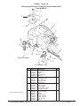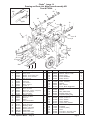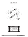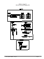
1
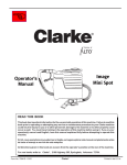
Division of
IMAGE 14
120V
Operator's
Manual
READ THIS BOOK
This book has important information for the use and safe operation of this machine. Failure to read this
book prior to operating or attempting any service or maintenance procedure to your Clarke machine
could result in injury to you or to other personnel; damage to the machine or to other property could
occur as well. You must have training in the operation of this machine before using it. If you or your
operator(s) cannot read English, have this manual explained fully before attempting to operate this
machine.
Si Ud. o sus operadores no pueden leer el Inglés, se hagan explicar este manual completamente antes
de tratar el manejo o servicio de esta máquina.
All directions given in this book are as seen from the operator’s position at the rear of the machine.
For new books write to: Clarke®, 2100 Highway 265, Springdale, Arkansas 72764.
Form No. 70088A 9/02
Clarke®
Printed in the U.S.A.
Table of Contents
Operator Safety Instructions ............................................................................................................ 3
Introduction & Machine Specifications ............................................................................................. 5
Instructions - Power Supply 120 Volt ................................................................................................ 6
Machine Controls ............................................................................................................................. 7
How To Prepare the Machine for Operation ....................................................................................... 7
How to Clean Carpet ........................................................................................................................ 8
OPERATOR'S MAINTENANCE:
How to Empty the Recovery Tank .............................................................................................. 9
How to Empty the Solution Tank ................................................................................................ 9
How to Attach the Auxiliary Floor Tool ........................................................................................ 10
After Each Use of the Machine .................................................................................................. 10
How to Prevent Damage from Freezing Temperatures ................................................................ 11
Spray Bar Nozzle ...................................................................................................................... 11
SECTION II Parts and Service Manual
AUTHORIZED PERSONNEL MAINTENANCE
To Access Pump/Brush Motor ................................................................................................... 14
Brush Drive Belt Replacement ................................................................................................... 14
Maintenance of the Vacuum Motor ............................................................................................. 14
Brush maintenance .................................................................................................................... 14
How to Correct Problems in the Machine ......................................................................................... 15
Final Assembly Drawing & Parts List Image 14 ................................................................................ 16
Handle Assembly Drawings & Parts List .......................................................................................... 17
Recovery Tank Assembly Drawing & Parts List ................................................................................ 18
Solution Tank Assembly Drawing & Parts List .................................................................................. 19
Brush/Pump Assembly Drawing & Parts List ................................................................................... 20
Main Frame Assembly Drawing & Parts List ................................................................................... 21
Pump Drawing & Parts List .............................................................................................................. 22
Connection Diagram 120 Volts .......................................................................................................... 23
Electrical Schematic 120 Volts ........................................................................................................ 24
Authentic Clarke Products ............................................................................................................... 25
Page 2
Clarke® Operator's Manual - Image 14
IMPORTANT SAFETY INSTRUCTIONS
WARNING
AVERTISSEMENT
ADVERTENCIA
DANGER:
Failure to read and observe all DANGER statements could result in severe
bodily injury or death. Read and observe all DANGER statements found in your
Owner's Manual and on your machine.
WARNING:
Failure to read and observe all WARNING statements could result in injury to
you or to other personnel; property damage could occur as well. Read and
observe all WARNING statements found in your Owner's Manual and on your
machine.
CAUTION:
Failure to read and observe all CAUTION statements could result in damage to
the machine or to other property. Read and observe all CAUTION statements
found in your Owner's Manual and on your machine.
WARNING:
To reduce the risk of fire, electric shock, or injury:
1. Do not leave appliance unattended when plugged in. Unplug from outlet when not in
use and before servicing.
2. To reduce the risk of electric shock use indoors only.
3. Do not allow to be used as a toy. Close attention is necessary when used by or near
children.
4. Use only as described in the manual. Use only manufacturer's recommended attachments.
5. Do not use with damaged cord or plug. If appliance is not working as it should, has
been dropped, damaged, left outdoors, or dropped into water, return it to a service
center.
6. Do not pull or carry by cord, use cord as a handle, close a door on cord, or pull cord
around sharp edges or corners. Do not run appliance over cord. Keep cord away from
heated surfaces.
7. Do not unplug by pulling on cord. To unplug, grasp the plug, not the cord.
8. Do not handle plug or appliance with wet hands.
9. Do not put any object into openings. Do not use with any opening blocked; keep free of
dust, lint, hair and anything that may reduce air flow.
10. Keep hair, loose clothing, fingers, and all parts of body away from openings and moving
parts.
11. Do not pick up anything that is burning or smoking, such as cigarettes, matches, or hot
ashes.
12. Do not use without filters in place.
13. Turn off all controls before unplugging.
14. Use extra care when cleaning on stairs.
15. Do not use to pick up flammable or combustible liquids such as gasoline or use in areas
where they may be present.
16. Connect to properly grounded outlet. See "Grounding Instructions".
SAVE THESE INSTRUCTIONS
Clarke® Operator's Manual - Image 14
Page 3
IMPORTANTES MESURES DE SECURITE
AVERTISSEMENT: Pour réduire les risques d'incendie,de choc électrique ou
de blessure:
1. Ne pas laisser l'appareil sans surveillance lorsqu'il est branché. Débrancher lorsque
l'appareil n'est pas utilisé et avant l'entretien.
2. Pour réduire les risques de choc électrique, utiliser à l'intérieur seulement.
3. Ne pas permettre aux enfants de jouer avec l'appareil. Une attention particuliére est
4. N'utiliser que conformément à cette notice avec les accessoires recommandés par le
fabricant.
5. Ne pas utiliser si le cordon ou la fiche est endommagé. Retourner l'appareil à un atelier
de réparation s'il ne fonctionne pas bien, s'il est tombé ou s'il a été endommagé, oublié à
l'extérieur ou immergé.
6. Ne pas tirer soulever ou traîner l'appareil par le cordon. Ne pas utiliser le cordon comme
une poignée, le coincer dans l'embrasure d'une porte ou l'appuyer contre des arêtes vives
ou des coins. Ne pas faire rouler l'appareil sur le cordon. Garder le cordon à l'écart des
surfaces chaudes.
7. Ne pas débrancher en tirant sur le cordon. Tirer plutôt la fiche.
8. Ne pas toucher la fiche ou l'appareil lorsque vos mains sont humides.
9. N'insérer aucun objet dans les ouvertures. Ne pas utiliser l'appareil lorsqu'une ouverture
est bloquée. S'assurer que de la poussière, de la peluche, des cheveux ou d'autres
matières ne réduisent pas le débit d'air.
10. Maintenir les cheveux, les vêtements amples, les doigts et toutes les parties du corps à
l'écart des ouvertures et des pièces mobiles.
11. Ne pas aspirer de matières en combustion ou qui dégagent de la fumée, comme des
cigarettes, des allumettes ou des cendres chaudes.
12. Ne pas utiliser l'appareil si le sac à poussière ou le filtre n'est pas en place.
13. Mettre toutes les commandes à la position ARRET avant de débrancher l'appareil.
14. User de prudence lors du nettoyage des escaliers.
15. Ne pas aspirer des liquides inflammables ou combustibles, comme de l'essence, et ne
pas faire fonctionner dans des endroits où peuvent se trouver de tels liquides.
16. "Ne brancher qu'à une prise de courant avec mise à la terre. Voir les instructions visant
la mise à la terre."
CONSERVER CES INSTRUCTIONS
Page 4
Clarke® Operator's Manual - Image 14
DANGER:
Machines can cause an explosion when operated near flammable materials and vapors. Do
not use this machine with or near fuels, grain dust, solvents, thinners, or other flammable
materials.
WARNING:
You must have training in the operation of this machine before using it. READ THE
INSTRUCTION BOOK FIRST.
WARNING:
Any alterations or modifications of this machine could result in damage to the machine or injury
to the operator or other bystanders. Alterations or modifications not authorized by the
manufacturer voids any and all warranties and liabilities.
WARNING:
Do not use this machine as a step or furniture. Injury could occur to the operator.
WARNING:
To avoid serious injury, use proper lifting procedures when lifting the machine.
WARNING:
Make sure that all the labels, decals, warnings, cautions and instructions are readable. Replace
them when necessary by ordering them from Clarke.
WARNING:
Do not use water that is hotter than 140°F.
WARNING:
Improper discharge of waste water may damage the environment and be illegal. The United
States Environmental Protection Agency has established certain regulations regarding
discharge of waste water. Also, city and state regulation regarding this discharge may be in
effect in your area. Understand and follow the regulations in your area. Be aware of the
environmental hazards of chemicals that you dispose.
Introduction and Machine Specifications
The Image 14 is an extractor for cleaning carpet. The machine applies cleaning solution to the carpet and removes
dirty solution and soil from the carpet. The Image 14 is equipped with a power brush. The extractor has controls to
start the solution pump, and vacuum motor. This machine is intended for commercial use.
Recovery Tank
Recovery Tank Handle
Control Switch
Solution Tank
Vacuum Hose
Locking
Handle
Specifications:
Model
Electrical
Solution Pump
Power Cable
Spray Jets
Solution Tank Capacit
Recovery Tank
Waterlift/CFM
Vacuum
Brush Size
Brush Motor Size
Dimensions
Weight
Shipping Weight
Recovery Tool
Image 14
120V
04120A
120 V. 50/60 Hz
45 PSI Bypass
35' 14/3-wire
1 Quarter Turn Q.C.
4 Gallon
4 Gallon
82"/97
Tangential discharge,
1.25 HP, 2 stage
3½" x 11"
1/8 HP
31½" x 37" x 14"
55 lbs.
65 lbs.
Clarke® Operator's Manual - Image 14
Self Adjusting Brush
Auxiliary Connection
Page 5
120 VOLT, 50/60 CYCLE MACHINES
GROUNDING INSTRUCTIONS
This product must be grounded. If it should malfunction or
breakdown, grounding provides a path of least resistance
for electric current to reduce the risk of electric shock. This
product is equipped with a cord having an equipmentgrounding conductor and grounding plug. The plug must be
inserted into an appropriate outlet that is properly installed
and grounded in accordance with all local codes and
ordinances.
WARNING: Improper connection of the
Grounded
Outlet
equipment-grounding conductor can result in a risk of electric shock. Check with a qualified electrician or service
Grounded
Outlet Box
person if you are in doubt as to whether the outlet is properly grounded. Do not modify the plug provided with the
product - if it will not fit the outlet, have a proper outlet in-
Grounding
Pin
stalled by a qualified electrician.
This product is for use on a nominal 120 volt circuit and has
a grounding attachment plug that looks like the plug
illustrated in Fig. 1. Make sure that the product is connected
to an outlet having the same configuration as the plug. No
adaptor should be used with this product.
Figure 1
For maximum protection against electric shock, use a circuit
that is protected by a ground fault circuit interrupter. The
green (or green and yellow) conductor in the cord is the
ground wire. Never connect this wire to any terminal other
than the ground terminal.
WARNING:
To prevent possible electric shock, protect the machine from rain. Keep the
machine in a dry building.
WARNING:
To prevent possible electric shock, always use a 3-wire electrical system connected to the electrical ground. For
maximum protection against electrical
shock, use a circuit that is protected by
a ground fault circuit interrupter. Consult your electrical contractor.
WARNING:
Do not cut, remove or break the ground
pin. If the outlet does not fit the plug,
consult your electrical contractor.
WARNING:
Have worn, cut, or damaged cords and
plugs replaced by an authorized service
person.
EXTENSION CORDS
Use only an approved extension cord with three conductors, a
plug with three terminals, and a connector body with three
holes. The machine has a power cord with wire size 14 AWG
(AWG means American Wire Gauge).
WARNING:
Page 6
If you use an extension cord, use an
extension cord with minimum wire
size 14 AWG. Do not use an extension cord longer than 50 feet. Do
not join two extension cords.
Clarke® Operator's Manual - Image 14
THE CONTROLS
The Vacuum/Accessory/Pump Switch
This switch is located on the handle. To turn the
vacuum motor on, place the switch in the middle
position. To turn pump, brush, and vacuum motor on,
place the switch in bottom position. (Figure 2, #1)
1
2
The Vacuum Hose Connector
The vacuum hose connector is on the right hand rear
of the machine. (Figure 2, #2)
The Solution Hose Connector
The solution hose connector is located on the bottom
center of the machine. This connection is used to
hook up optional auxiliary floor tools. (Figure 2, #3)
Recovery Tank Drain
Remove hose from rear of machine. Using the handle
lift the recovery tank free and and pour water into
drain.
Solution Tank Drain
Remove the hose from the rear of the machine. Place
over drain.
3
Figure 2
HOW TO PREPARE THE MACHINE FOR OPERATION
WARNING: This machine has moving parts.
To reduce the risk of injury, unplug
before servicing.
WARNING: To reduce the risk of fire, use only
commercially available floor cleaners and waxes intended for machine
application.
WARNING: Do not use water that is hotter than
140°F.
WARNING: Operating a machine that is not completely or fully assembled could result in injury or property damage.
Do not operate this machine unless
it is completely assembled. Inspect
the machine carefully before operating.
CAUTION:
Do not leave the extractor or
other cleaning machines or
tools on the carpet when not in
use. Cleaning solution in the
machines and tools can leak
onto the carpet and cause light
spots or stains.
NOTE: To order Clarkare® Extractor Concentrate,
Order Part No. 398421. To order Clarkare®
Defoamer, order Part No. 398420. For instructions
for preparation and operation of your floor tool,
read the operator's manual
supplied with your floor tool.
This machine is intended for commercial use.
To prepare the machine for operation, follow this
procedure:
1. Before moving the extractor onto the carpet, put
clean hot water into the solution tank. The solution
tank capacity is approximately four gallons.
2. Add two to ten ounces of "Clarkare® Extractor
concentrate" per every one gallon of water, depending on carpet condition.
3. If the extractor removes an excess amount of foam
from the carpet, add a defoamer such as Clarkare®
Defoamer Concentrate to the recovery tank. The
amount needed will change according to the
amount of detergent already in the carpet.
Clarke® Operator's Manual - Image 14
Page 7
HOW TO CLEAN AN AREA OF CARPET
CAUTION:
The recovery tank is equipped
with a mechanical shut-off float
switch. When the recovery tank
becomes full the machine will
no longer recover water. Turn
the vacuum/accessory and
spray/brush/switch to the "O"
position before emptying the recovery tank.
NOTE: When using the extractor to clean carpets,
follow this procedure:
1. Do not walk on freshly cleaned carpets for at
least four hours or until the carpet is dry to
touch.
2. If aluminum or plastic pieces have been placed
under the legs of furniture, do not
remove them until the carpet is dry.
3. Do not allow children or pets to crawl or walk
around on the damp carpet.
4. Vacuum right after the carpet is dry and then
vacuum the carpet once a week, or as often as
needed.
Figure 3
To clean an area of carpet, follow this procedure:
(See Figure 3)
1. Dry Vacuum area of carpet to be cleaned.
2. Turn the Vacuum switch to the "ON" position.
3. Brush will self adjust.
NOTE:
Incorrect brush height may cause
circuit breaker to trip. Check for obstructions in
brush housing , clear and proceed.
4. With the pump switch activated, slowly and
steadily pull the machine backwards.
5. Switch to Pump "OFF" and vacuum an additional 6 inches.
6. To clean a small area of carpet, clean the carpet
in sections three feet square. As you make
additional passes, overlap one inch of the area
already cleaned.
7. Cleaning speed is determined by how dirty the
carpet is. If the carpet is very dirty, move the
machine slower.
8. As the machine is used, dirty solution will begin
to fill the recovery tank. When the solution tank
is empty, the recovery tank must be emptied.
Page 8
Clarke® Operator's Manual - Image 14
To clean a larger area of carpet, follow this procedure:
(See Figure 4)
3
1
1. Begin at the right-hand corner of the carpet.
2. Make a pass halfway along the edge of the carpet.
Pull the machine backward at a steady speed.
3. Move to the edge of the carpet. Make another pass
next to your first pass.
4. As you make more passes, overlap one inch of the
area already cleaned. Make each pass four inches
different in length to prevent making a line in the
center of the carpet.
5. Make more passes until half of the carpet is
cleaned.
5
4
2
9
7
6
Figure 4
6. Move to the right hand corner of the carpet not yet
cleaned.
7. Make a pass halfway along the edge of the carpet.
8. As you make passes, overlap one inch of the area
already cleaned.
9. Make more passes until all of the room is cleaned.
CAUTION: Clarke will not be held liable for damage to the carpet, or poor results because of the operator's lack of ability.
OPERATOR'S MAINTENANCE
How to Empty the Recovery Tank
To empty the recovery tank, follow this procedure:
1. Turn the switches on the machine to the "O" position.
2. Remove the hose on the rear of the recovery tank.
Lift recovery tank by handle and carry to drain.
3. Using drain spout, pour into drain.
How to Empty the Solution Tank
1. Turn switches to the "O" position.
2. Position the machine near a drain. Remove the hose
from the rear of the machine and place hose into
drain.
Clarke® Operator's Manual - Image 14
Page 9
MAINTENANCE (cont)
How To Attach The Auxiliary Floor Tool
To attach the auxiliary floor tool, follow this procedure:
1. Remove the vacuum hose from the recovery
tank.
2. Connect the auxiliary floor tool vacuum hose to
the recovery tank and to the auxiliary tool.
3. Move and hold the brush height lever (figure 5)
away from the auxillary connection. Make
connection and release brush height lever (will
rest against connection). See figure 5a.
4. Connect the solution hose to the machine and
to the floor tool.
Figure 5
5. Turn solution valve to accessory position.
6. Turn the vacuum and pump switch "ON".
7. Operate the optional cleaning tool as normal.
8. When finished cleaning with the optional floor
tool, turn the switches "OFF".
NOTE: Auxiliary floor tools recommended for this
machine:
19209A - RM4 (Upholstery)
19212A - RM9 (9" Floor Wand)
785401 - RM10 (10" Floor Wand)
59220A - Plastic Hand Tool 4" (Upholstery)
NOTE: For maintenance of the optional floor tools,
read the manual supplied with the tools.
After Each Use Of The Machine:
Figure 5a
1. To prevent damage to valves and jets, flush one
gallon of clean water
through the solution system and the tools.
2. Disconnect the power cord from the outlet and wrap
around the handle.
3. Drain the recovery tank.
4. Rinse out the recovery tank.
5. Use a dry cloth to wipe both tanks and tools, inside and out.
6. Inspect and clean the screen filter in the solution
tank.
7. To prevent clogged jets due to alkaline buildup, the
spray system should be flushed at least twice a
month with either a white vinegar solution
(one quart vinegar to one gallon of hot water) or an
anti-browning solution (mixed as directed).
8. Remove any lint on the vacuum intake screen. The
screen is located under the recovery tank and on
the rear of the machine.
Page 10
Clarke® Operator's Manual - Image 14
How to Prevent Damage From Freezing Temperatures
To prevent damage from freezing temperatures, follow this
procedure:
1. Remove any solution remaining in the solution tank.
2. Make sure the machine and pump are completely dry.
3. Pour windshield-type antifreeze into the solution tank
until the screen in the filter is covered.
4. Turn on the vacuum/accessory switch and the spray/
brush switch for 30 seconds.
5. Remove antifreeze solution from the system before using the extractor.
6. Make sure the machine is the same temperature as the
room before using the machine.
Spray Bar - Nozzles
To clean or quick change the nozzles follow this procedure:
1. Grasp the nozzle, push in and twist 1/4 of a turn to remove nozzle from the body.
2. Clean or replace the nozzle.
4. Push in and twist nozzle back into the body.
NOTE: Performance will drop if the factory nozzle configuration is changed.
WARNING: Maintenance and repairs must be done
by authorized personnel only. Keep all
fasteners tight. Use only Clarke parts.
Maintenance performed by someone
other than a Clarke distributor or Clarke
replacement parts could void your warranty.
Electrical
WARNING: Electrical repairs must be done by authorized personnel only.
WARNING: After electrical repairs are done to the
machine, the machine must be tested for
electrical safety.
Page 11
CLARKE Operator's Manual - Image 14
NOTES
Page 12
Clarke® Operator's Manual - Image 14
Division of
Image 14
Section II
Parts and Service Manual
(70088A)
Clarke® Operator's Manual - Image 14
Page 13
AUTHORIZED PERSONNEL MAINTENANCE
To Access Pump/Brush Unit
Brush Maintenance
1. Remove six (6) screws in rear plate that secure
solution tank to machine.
1. Remove (6) screws in rear plate that secure
solution tank to machine.
2. Remove solution tank from machine.
2. Remove solution tank from machine.
3. Disconnect pump ground wire from ground screw.
3. Remove screws holding brush cover on.
Remove brush cover.
4. Remove solution hoses.
5. Remove two (2) mounting screws that secure pump
motor to frame.
6. Reverse procedures for installing new pump. Check
wiring diagram for proper connections when reinstalling electrical parts.
4. Remove (2) screws holding brush assembly in
place and replace brush.
5. Carefully pry brush pivot out from bearing (applying pressure unevenly can break brush
pivot).
6. Add a small amount of grease to face of seal
and bearing on I.D. of brush core.
Brush Drive Belt Replacement
7. Reassemble in reverse order.
1. Remove (6) screws in rear plate that secure solution tank to machine.
2. Remove solution tank from machine.
3. Remove screws holding brush cover on. Remove
brush cover.
4. Remove (2) screws holding brush assembly in
place and replace belt.
5. Reassemble in reverse order.
Maintenance of the Vacuum Motor
This machine has a vacuum motor that uses carbon
brushes. The carbon brushes in the motor must be
checked every three months, or every 500 hours of
operation, whichever comes first. If either of the
brushes is shorter than 3/8 inch, replace both of the
carbon brushes.
To gain access to the vacuum motor:
1. Remove (6) screws in rear plate that secure solution tank to machine.
2. Remove solution tank from machine.
3. Access the brushes or the (3) bolts that secure
the vacuum motor to tank.
Page 14
Clarke® Operator's Manual - Image 14
HOW TO CORRECT PROBLEMS IN THE MACHINE
PROBLEM
CAUSE
ACTION
The machine will not run.
1. Machine does not have power...
1. Make sure the machine is connected
to the correct frequency and voltage,
and all connections are tight.
There is no suction.
1. Vacuum motor may not be running...
1. Be sure the vacuum/accessory switch
is at the vacuum/accessory position.
2.
2. Remove and clean lint screen on
vacuum stand pipe.
Vacuum intake screen clogged.
3. There may be a loose motor connection.
3. Contact an authorized service person.
4. There may be an obstruction in the
vacuum hose....
4. Remove the obstruction.
5.
5. Replace the motor brushes.
Motor brushes may be worn...
6. Drain may be open...
6. Connect recovery hose.
7. Dome may be worn or
damaged...
7. Replace the gasket or dome.
8. Vacuum hose may be damaged...
8. Replace the hose.
9. Vacuum/Accessory switch
may be defective.....
9. Contact an authorized service person.
1. The Accessory/Floor valve may be
in wrong position..
1. Turn the valve to Floor positon.
2. The spray tip may be dirty, plugged or
worn...
2. Clean or replace the tip.
3. The hose may be kinked...
3. Inspect the hose.
4. Inline filter may be plugged...
4. Clean filter.
5. Out of solution...
5. Add solution to tank.
1. The spray tips may be plugged...
1. Clean the spray tips.
2. The solution screen may be plugged...
3. Clean and replace.
3. The pump may be worn...
4. Contact an authorized service person.
4. The hose may be kinked...
5. Inspect the hose.
1. There may be a faulty seal in the pump..
1. Contact an authorized service person.
2. The pump may be worn....
2. Contact an authorized service person.
The float switch may not
be shutting off or turning on.
1. The ball may be damaged or obstructed
1. Inspect and clear obstruction.
Brush motor doesn't run.
1. Circuit breaker tripped...
1. Reset circuit breaker.
2. Switch is bad...
2. Contact an authorized service person.
3. Motor is bad....
3. Contact an authorized service person.
4. Belt is broken....
4. Contact an authorized service person.
Uneven or no spray from
the jets.
The solution pump runs
but no solution comes out
of the spray nozzle.
The solution pump leaks.
Clarke® Operator's Manual - Image 14
Page 15
Clarke® Image 14
Drawing and Parts List Final Assembly 4/98
2
10
13
1
3
4
5
6
12
7
8
9
11
Ref.
1
2
3
4
5
6
7
8
9
10
11
12
13
Page 16
Part No.
Page 15
Page 16
Page 17
Page 18
80013A
Page 19
82509A
58540A
925004
68504A
85397A
85398A
57427A
Description
Handle Assembly
Recovery Tank Assembly
Solution Tank Assembly
Brush/Pump Assembly
Bolt, Shoulder
Main Frame Assembly
Pin, Clevis
Spacer
Pin, Cotter
Drain, Preventor
Screw, 10-24 x 3/8 S.S.
Screw, ¼-20 S.S.
Retainer, Power Cord
Qty
1
1
1
1
2
1
2
2
2
1
2
4
1
Clarke® Operator's Manual - Image 14
Clarke® Image 14
Drawing & Parts List, Handle Assembly 4/98
Form #15347A
6
1
6
4
5
3
2
To main frame
assembly
Ref.
Part No.
Description
1
2
3
4
5
6
34811B
57002A
55538A
49761B
56459A
47411A
Handle, Control
Post, Knob
Knob, Handle Lock
Harness, Wiring
Strain Relief (supplied w/item 4)
Switch, Control
Clarke® Operator's Manual - Image 14
Qty
1
2
2
1
1
2
Page 17
Clarke® Image 14
Drawing and Parts List, Recovery Tank Assembly 9/02
Form #10450A
7
8
9
18
10
1
13
6
11
2
5
14
3
15
12
4
17
16
Page 18
Ref.
Part No.
Description
1
2
3
4
5
6
7
8
9
10
11
12
13
14
15
16
17
18
692409
86303A
81901A
30290A
962954
55670A
31803A
50805A
34286A
57425A
85606A
84237A
962987
34288A
980982
85397A
69893A
920224
Chain, Cover
Screw, #10-24 x 1.25
Nut, #10-24
Tank, Recovery
Screw, 10-24 x 3/8
Lid, Recovery
Chamber, Vac
Ball, Float Shut Off
Gasket, Vac Chamber
Retainer, Flat
Screw, 10-32 x 3" Pan Hd SS
Screw, 10-32 x ½
Screw, Hi-Lo
Gasket, Recovery Lid
Washer, #10
Screw
Bracket, Retaining
Nut
Qty
1
1
1
1
4
1
1
1
1
1
3
4
1
1
4
2
1
1
Clarke® Operator's Manual - Image 14
Clarke® Image 14
Drawing and Parts List, Solution Tank Assembly 9/02
Form #10451A
1
2
20
3
17
4
16
5
6
13
15
23
5
21
7
8
13
14
12
To Vacuum Motor
10
18
22 19
To Recovery Tank
*Note: Service Item Only
Ref.
Part No.
Description
1
2
3
4
5
6
7
8
9
10
11
12
13
14
15
16
17
18
19
20
21
22
23
56476A
54371A
85398A
30288A
51518A*
52417A*
52414A
28205A
67616A
87026A
80018A
55166A
872010
30441A
30419A
60321A
58068A
962333
980603
73379A
722021
48911A
35138A
Strainer, Vacuum
Gasket, Vac
Screw
Tank, Solution
Bushing
Connector, 3/8 x ¼
Connector, Hose
Tool, Recovery
Shoe, Recovery
Washer, S.S.
Shoulder Bolt
Hose, Recovery
Clamp, Hose
Hose, Solution Drain
See Page 19, #12
Adaptor, Weldment
Screen, Solution
Screw
Washer, Lock
Label, Lift Here
Clamp, Hose #4
Wire, Ground
Hose
Clarke® Operator's Manual - Image 14
9
11
Qty
1
1
2
1
3
1
2
1
2
2
2
1
3
1
1
1
2
1
1
3
1
1
Page 19
Clarke® Image 14
Drawing and Parts List, Brush/Pump Assembly 9/01
Form #17651A
1
6
2
5
28
4
27
24
23
3
22
25 26
4
29 21
5
6
11
20
9
2
7
12
18
12
16
17
14
15
13
11
30
13
Ref.
Part No.
Description
1
2
3
4
5
6
7
9
11
12
13
14
15
16
32400A
920056
51713A
902648
53047A
66221A
34110A
55167A
53616A
85837A
85607A
980410
54169A
980603
Cover, Brush
Nut, 6 x 32 Elastic
Brush, Carpet
Brg, Ball Radial
Seal
Pivot, Brush
Guard, Splash
Hosebarb, ¼ x 3/8
Elbow, 3/8 MPT x 3/8 Hosebarb
Screw, 10-24 x ¼ Pn. Hd.
Screw, 6-32 x 3/8
Washer, Stainless Steel
Nozzle, Spray
Washer, Star
Qty
Ref.
Part No.
Description
1
7
1
2
2
2
1
1
2
2
7
2
1
2
17
18
20
21
22
23
24
25
63535A
32408A
35147A
47711A
57271A
962628
50926A
51714A
51719A
980202
66187B
925549
911933
30078A*
Frame, Brush/Pump
Guard, Pulley
See page 19 ref. #45
Terminal, ¼ FIFQD
Pulley, Timing
Screw, Set
Belt, Timing
Brush/Pump Unit 120V
Brush/Pump Unit 230V
Washer, Wave
Sprocket
Pin, 3/16 x 1½
Terminal
Stainer, Spray Jet
26
27
28
29
30
* Optional Accessory
Page 20
Clarke® Operator's Manual - Image 14
Qty
1
1
2
1
2
1
1
1
1
1
1
1
1
Clarke® Image 14
Drawing and Parts List, Main Frame Assembly 9/01
Form #17650A
48
2
47
25b
48
50
46
49
44
38
25a
2
12
2
4
1
45
11
28
5
6
30
26
7
4
8
10
49
5
9
13
10
14
27
39
25
11A
34
24
49
43
23
35
37
40
42
27
15
29
41
32
28
18
31
17
22
21
20 19 33
Ref.
1
2
4
5
6
7
8
9
10
11
11a
12
13
14
15
16
17
18
19
20
21
22
23
24
25
16
Part No.
732870
50248A
41427A
41430A
920224
46103A
59728A
170066
170040
82100A
44923A
44924A
40833A
30419A
81102A
87026A
58537A
59951A
920346
674111
697501
737140
Description
Elbow, ¼ MPT x 3/8
Clamp, Hose
Breaker, Circuit w/ Nut 120V
Breaker, Circuit .6A 230V
Nut, Hex 10-32
Rectifier
Valve, Plug
Tee, Brass ¼
Elbow , Street ¼
Locknut, ½
Motor, Vac 120V
Motor, Vac 230V
Brush Asm., Carbon (2-required)
Hose, Vac Squeege
Nut, Stop Elastic
Washer, .250 Flat
Spacer, Vac Motor
Wheel, 8"
Palnut
Hose, Exhaust,Dual
Reducer, ¼ NPT
Quick Disconnect
Qty
1
6
1
1
3
1
1
1
1
2
1
1
1
1
3
3
3
2
2
1
1
1
611101
85742A
85608A
58013A
42188A
42235A
Bushing, Motor
Screw, ¼-20, 5.00
Screw, 10-32 x 3/4
Strain Relief
Cord, Power 120V
Cord, Power 230V
1
3
1
1
1
1
Clarke® Operator's Manual - Image 14
Ref.
Part No.
Description
26
27
28
29
30
31
32
33
34
35
36
37
38
39
41
42
43
44
45
46
47
48
49
50
51*
52**
170030
980603
872010
63536A
77094A
57424A
77345A
980410
954010
32411A
53619A
87626A
49080A
69894A
47201A
962987
85833A
35176A
35147A
59621A
47711A
911933
47704A
35172B
40164A
40149A
Hosebarb, 3/8
Washer, #10 Ext. Tooth
Clamp, Hose
Frame Weldment
Label, Ground
Brush Height Rod
Label, Accessory
Washer
Wire, Ground
Cover, Brush Height Rod
Adaptor ¼NPT x 3/8 Barb
Washer
Wire, Main Power
Bracket (230V only)
Supressor (230V only)
Screw, 10-24 x 3/8 (230V only)
Screw, 10-32 x 3/8
Hose, Solution
Hose, Solution
Check Valve, Solution
Terminal (230 V)
Terminal
Terminal (120V)
Hose
Cord Asm., 35' Power 120V
Cord Asm., Power 230V
Qty
Page 21
1
4
2
1
1
1
1
3
1
1
1
1
1
1
1
2
1
1
1
1
2
1
1
1
1
1
Clarke® Image 14 115V
Drawing and Parts List 10/97
Brush/Pump Unit
3
2
1
6
5
4
Ref.
Part No.
Description
1
2
55446A
55447A
Check Valve Assembly
Kit, Upper Housing
Qty
1
1
3
4
55448A
55449A
Kit, Bypass Valve Assembly
Kit, Diaphragm
1
1
5
6
55450A
44926A
Kit, Drive Assembly
Motor
1
1
7
*55174A
Head, Pump, 45 psi
1
NOTE: *55174A (includes # 1,2,3,& 4 assembled)
Page 22
Clarke® Operator's Manual - Image 14
Clarke® Image 14
120 Volt Connection Diagram 3/98
Clarke® Operator's Manual - Image 14
Page 23
Clarke® Image 14
120 Volt Electrical Schematic 03/98
Page 24
Clarke® Operator's Manual - Image 14
Authentic Clarke® Products 9/01
6
3
7
8
9
4
10
2
5
1**
Ref
1
2
3
4
5
6
7
8
9
10
11
ASM
NI
Part No.
30108A
59231A
59230A
59229A
59232A
59228A
398426
398425
398427
55183A
52953A
55173A
68204A
Description
Adaptor, 2" to 1½
RM-4P Tool Assembly
RM-8P Tool Assembly
RM-12M Tool Assembly
Hide-A- Hose 10'
RM-4M Tool Assembly
Defoamer
Extractor, Concentrate
Traffic Lane/Spot Cleaner
Hide-A-Hose 20'
General Purpose Spot Cleaner
4" Hand Tool and 10' Hose Asm.
Coupler, 1½" Hose Connector
Qty
1
1
1
1
1
1
*1 case
*1 case
*1 case
1
1 case
1
1
* 4, 1 gallon bottles
**Required to use any accessory
Image 14 Owner's Manual
11
Page 25
NOTES
PRODUCT SUPPORT BRANCHES
U. S. A. Locations
HEAD OFFICE
European Locations
PRODUCTION FACILITIES
ALTO U.S. Inc., St. Louis, Missouri
16253 Swingley Ridge Road, Suite 200
Chesterfield, Missouri 63017-1725
PRODUCTION FACILITIES
Clarke®, Springdale, Arkansas
2100 Highway 265
Springdale, Arkansas 72764
(479) 750-1000
Customer Service - 1-800-253-0367
Technical Service - 1-800-356-7274
American Lincoln®, Bowling Green, Ohio 43402
1100 Haskins Road
SERVICE FACILITIES
Clarke® , Carlstadt, New Jersey 07072
150 Commerce Road
(201) 460-4774
Clarke®, Elk Grove, Illinois 60007
2280 Elmhurst Road
(847) 956-7900
Clarke®, Denver, Colorado 80204
1955 West 13th Ave.
(303) 623-4367
Clarke®, Houston, Texas 77040
7215 North Gessner Road
SALES AND SERVICE FACILITIES
American Lincoln® / Clarke®, Madison Heights,
Michigan 48071-0158
29815 John R.
(810) 544-6300
American Lincoln® / Clarke®, Marietta, Georgia 30062
1355 West Oak Common Lane
(770) 973-5225
Clarke®
Clarke American Sanders
A.L. Cook
Customer Service Headquarters and Factory
2100 Highway 265
Springdale, Arkansas 72764
(479) 750-1000
Technical Service
1-800-356-7274
ALTO Danmark A/S, Aalborg
Blytaekkervej 2
DK-9000 Aalborg
+45 72 18 21 00
ALTO Danmark A/S, Hadsund
Industrikvarteret
DK-9560 Hadsund
+45 72 18 21 00
SALES SUBSIDIARIES
Clarke® Canada Ltd., Rexdale Ontario
24 Constellation Ct.
(416) 675-5830
ALTO Overseas Inc., Sydney (Australia)
1B/8 Resolution Drive
Caringbah NSW 2229
+61 2 9524 6122
ALTO Cleaning Systems Asia Pte Ltd., Singapore
No. 17 Link Road
Singapore 619034
+65 268 1006
ALTO Deutschland GmbH, Bellenberg (Germany)
Guido-Oberdorfer-Straße 2-8
89287 Bellenberg
+49 0180 5 37 37 37
ALTO Cleaning Systems (UK) Ltd., Penrith
Gilwilly Industrial Estate
Penrith
Cumbria CA11 9BN
+44 1768 868 995
ALTO France S.A. Strasbourg
B.P. 44, 4 Place d’Ostwald
F-67036 Strasbourg
Cedex 2
+33 3 8828 8400
ALTO Nederland B.V. Vianen
Stuartweg 4C
NL-4131 NJ Vianen
+31 347 324000
ALTO Sverige AB, Molndal (Sweden)
Aminogatan 18
Box 4029
S-431 04 Molndal
+46 31 706 73 00
ALTO Norge A/S, Oslo (Norway)
Bjornerudveien 24
N-1266
+47 2275 1770
Clarke® U.S. WARRANTY
This Clarke Industrial/Commercial Product is warranted to be free from defects in materials and workmanship under normal use and service for a period of one year from the date of purchase, when operated and
maintained in accordance with Clarke's Maintenance and Operations Instructions.
This warranty is extended only to the original purchaser for use of the product. It does not cover normal wear
parts such as electrical cable, rubber parts, hoses and motor brushes.
If difficulty develops with the product, you should:
(a). Contact the nearest authorized Clarke repair location or contact the Clarke Service Operations Department, 2100 Highway 265, Springdale, Arkansas 72764, for the nearest authorized Clarke repair location.
Only these locations are authorized to make repairs to the product under this warranty.
(b). Return the product to the nearest Clarke repair location. Transportation charges to and from the repair
location must be prepaid by the purchaser.
(c). Clarke will repair the product and or replace any defective parts without charge within a reasonable time
after receipt of the product.
Clarke's liability under this warranty is limited to repair of the product and/or replacement of parts and is
given to purchaser in lieu of all other remedies, including INCIDENTAL AND CONSEQUENTIAL DAMAGES.
THERE ARE NO EXPRESS WARRANTIES OTHER THAN THOSE SPECIFIED HEREIN. THERE ARE NO
WARRANTIES WHICH EXTEND BEYOND THE DESCRIPTION OF THE FACE HEREOF. NO WARRANTIES,
INCLUDING BUT NOT LIMITED TO WARRANTY OF MECHANTABILITY, SHALL BE IMPLIED. A warranty
registration card is provided with your Clarke product. Return the card to assist Clarke in providing the
performance you expect from your new floor machine.
Clarke, 2100 Highway 265, Springdale, Arkansas 72764.
Clarke® : POLYDUR TANK
U.S. EIGHT YEAR GUARANTEE
Your new Image Extractor has a Polydur Tank. Polydur is a rotationally molded, high-density linear polyethylene that won't crack or dent, and withstands most corrosives and temperature extremes. Clarke backs up your
Polydur Tank with its eight year gaurantee. If a tank breaks, cracks, or leakss, within eight years, it will be
replaced free.
Clarke reserves the right to make changes or improvements to its machine without notice.
Always use genuine Clarke Parts for repair.
Division of
2100 Highway 265
Springdale, Arkansas 72764