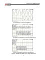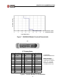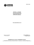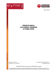
1
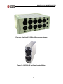
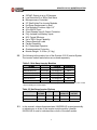
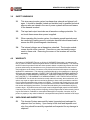
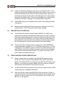
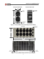
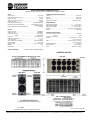
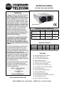
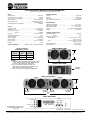
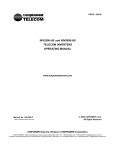
GRAVITAS IX12.5 SINE WAVE INVERTER SYSTEM OPERATING MANUAL www.unipowertelecom.com Manual No. IX12.5-703-2 IX12.5-Man-RevB-12-07-05 © 2005 UNIPOWER Corp. All Rights Reserved UNIPOWER Telecom, Division of UNIPOWER Corporation NORTH AMERICA • 3900 Coral Ridge Drive, Coral Springs, Florida 33065, USA • Tel: +1 954-346-2442 • Fax: +1 954-340-7901 • [email protected] EUROPE • Parkland Business Centre, Chartwell Road, Lancing BN15 8UE, ENGLAND • Tel: +44(0)1903 768200 • Fax: +44(0)1903 764540 • info@unipower-europe. CONTENTS SECTION TOPIC PAGE 1.0 Introduction 1 2.0 Features and Product Line 1 3.0 Safety Warnings 4 4.0 Warranty 4 5.0 Unpacking and Inspection 4 6.0 Description of Operation 5 7.0 Front and Back Panel Descriptions 5 8.0 Specifications 7 9.0 Safety and Industry Standards 8 10.0 Operating Information 8 11.0 Parallel Operation 14 12.0 Testing the Inverter Modules 14 13.0 Inverter System Application 15 14.0 Replacing An Inverter Module 16 15.0 Maintenance 17 16.0 Troubleshooting Guide 17 Appendix 1 Gravitas IX 12.5 Data Sheet A1 Appendix 2 INV2500-HS Data Sheet A2 ILLUSTRATIONS FIGURE TITLE PAGE 1 Gravitas IX12.5 System and Hot-Swap Module 2 2 Front & Back Views of Hot-Swap Inverter Module 6 3 Front & Back Panels of IX12.5 Inverter System 6 4 Rear Input, Output and Signal Connections 9 5 Front Panel AC Output Circuit Breakers 9 6 INV2500-HS Inverter Output Waveforms 11 7 INV2500-HS Overload Characteristic 12 8 Inverter Module Pin Connections 12 GRAVITAS IX12.5 INVERTER SYSTEM OPERATING MANUAL GRAVITAS IX12.5 SINE WAVE INVERTER SYSTEM OPERATING MANUAL 1.0 2.0 INTRODUCTION 1.1 This Operating Manual should be read through carefully before installing and operating the IX12.5 Sine Wave Inverter System. 1.2 The IX12.5 Inverter System consists of a model INVR5U-HS shelf with up to five model INV2500-HS hot-swap inverter modules. See Figure 1. Each module converts a nominal 48VDC (42 to 56V range) into a 115 or 230VAC output at 50 or 60Hz. There are six different module models. The modules have outputs automatically connected in parallel, and are current shared and frequency synchronized in the shelf. The shelf is 23 inches wide and 5U high (8.5 inches). There are two shelf models: one for 115VAC and the other for 230VAC. 1.3 Each INV2500-HS module produces 2500 volt-amperes output; a full shelf with five modules produces 12.5kVA output. Output current of each module is 22A at 115VAC or 11A at 230VAC. The output current of the fivemodule system is 110A at 115VAC or 55A at 230VAC. The inverter modules are 90% efficient with 7VA per cubic inch power density. The shelf has six output load circuit breakers. 1.4 The inverter system can also be operated as a hot-swap replacement, redundant power system. A 4+1 redundant system produces 115VAC at 88A or 230VAC at 44A (10kVA). 1.5 Each inverter module has input and output circuit breaker protection. They have high surge capability for starting loads such as motors, but the output breaker quickly trips if power attempts to flow back into a faulted inverter module. The modules are fully isolated from the battery. Front panel LEDs indicate inverter status, and relay alarm contacts are available on the back. The units are self-cooled by internal fans. FEATURES AND PRODUCT LINE 2.1 The following is a summary of the important features of the IX12.5 Sine Wave Inverter System: Up to 12.5kVA Output 10kVA Output, 4+1 Redundant 115 VAC Output at up to 110 Amperes 1 GRAVITAS IX12.5 INVERTER SYSTEM OPERATING MANUAL Figure 1a. Gravitas IX12.5 Sine Wave Inverter System Figure 1b. INV2500-HS Hot-Swap Inverter Module 2 GRAVITAS IX12.5 INVERTER SYSTEM OPERATING MANUAL 2.2 230VAC Output at up to 55 Amperes Low Distortion 50 or 60Hz Sine Wave Microprocessor Controlled 23” Shelf Holds Five Inverter Modules Hot-Swap Replacement in Shelf Five Mounting Positions High: 8.5” 42 to 56VDC Input Circuit Breaker Input & Output Protection Fully Isolated from Battery Inputs 90% Typical Efficiency Up to 300% Surge Capability Powers Reactive Loads Parallel Capability N+1 Redundant Operation Overtemperature Protection Module Weight: 11.65 lbs. (5.3 kg.) The following is the product line of the Gravitas IX12.5 Inverter System. The inverter module and shelves are ordered separately. Table 2.1 Hot-Swap Inverter Modules MODEL INPUT OUTPUT FREQUENCY INV2500-HS-60-E 42-56VDC 115VAC@22A 60Hz INV2500-HS-50-E 42-56VDC 115VAC@22A 50Hz INV2500H-HS-60-E 42-56VDC 230VAC@11A 60Hz INV2500H-HS-50-E 42-56VDC 230VAC@11A 50Hz INV2500-HS-60* 42-56VDC 115VAC@22A 60Hz INV2500-HS-50* 42-56VDC 115VAC@22A 50Hz *NOTE: These two models have the AC neutral output grounded to chassis. The other four models (-E) have floating AC neutral outputs. Table 2.2 Hot-Swap Inverter Shelves MODEL OUTPUT VOLTAGE SIZE HEIGHT MODULE CAPACITY MAXIMUM OUTPUT INVR5U-HS-B 115VAC 23-Inch 5RU 5 12.5kVA INVR5U-HS-B-H 230VAC 23-Inch 5RU 5 12.5kVA *NOTE: Both shelves have floating neutral outputs. 2.3 In this manual, unless otherwise stated, INV2500-HS is used generically to indicate any or all six of the inverter module models. Likewise INVR5U-HS is used to indicate either or both of the shelf models. 3 GRAVITAS IX12.5 INVERTER SYSTEM OPERATING MANUAL 3.0 4.0 SAFETY WARNINGS 3.1 This sine wave inverter system has hazardous external and internal voltages. It should be handled, tested and installed only by qualified technical persons who are trained in the use of power systems and are well aware of the hazards involved. 3.2 The input and output terminals are at hazardous voltage potentials. Do not touch these areas when power is applied. 3.3 When operating this inverter system, the chassis ground terminals must be connected to safety ground to minimize electrical shock hazard and to ensure low EMI (electromagnetic interference). 3.4 The internal voltages are at hazardous potentials. The inverter module covers should not be removed. There are no user-serviceable components in these units. Removing the covers of the inverters will void the warranty. WARRANTY All products of UNIPOWER Telecom, a division of UNIPOWER Corporation, are warranted for two (2) years from date of shipment against defects in material and workmanship. This warranty does not extend to products which have been opened, altered or repaired by persons other than persons authorized by the manufacturer or to products which become defective due to acts of God, negligence or the failure of customer to fully follow instructions with respect to installation, application or maintenance. This warranty is extended directly by the manufacturer to the buyer and is the sole warranty applicable. EXCEPT FOR THE FOREGOING EXPRESS WARRANTY, THE MANUFACTURER MAKES NO WARRANTY, EXPRESS OR IMPLIED, INCLUDING, BUT NOT LIMITED TO, THE WARRANTY OF MERCHANTABILITY OR FITNESS FOR A PARTICULAR PURPOSE. As the sole and exclusive remedy under this warranty, the manufacturer, at its option, may repair or replace the non-conforming product or issue credit, provided the manufacturer’s inspection establishes the existence of a defect. To exercise this remedy, the buyer must contact the manufacturer’s Customer Service Department to obtain a Return Material Authorization number and shipping instructions. Products returned without prior authorization will be returned to buyer. All products returned for repair must be shipped freight prepaid to UNIPOWER. If the buyer fails to fully comply with the foregoing, the buyer agrees that no other remedy (including, but not limited to, incidental or consequential damages for lost profits, lost sales, injury to person or property or any other incidental or consequential losses) shall be available to the buyer. 5.0 UNPACKING AND INSPECTION 5.1 This Inverter System was carefully tested, inspected and packaged for shipment from our factory. Upon receipt of the shelf and separate modules, they should be carefully unpacked and inspected for any damage in shipment. 4 GRAVITAS IX12.5 INVERTER SYSTEM OPERATING MANUAL 6.0 7.0 5.2 If there is evidence of damage to any unit, do not attempt to test it. The freight carrier should be notified immediately and a claim for the cost of the unit should be filed with the carrier for direct reimbursement. Be sure to include the model and serial number of the damaged unit in all correspondence with the freight carrier. Also save the shipping carton and packing material as evidence of damage for the freight carrier’s inspection. 5.3 UNIPOWER Telecom will cooperate fully in case of any shipping damage investigation. 5.4 Always save the packing materials for later use in shipping a unit of the inverter system. Never ship a unit without proper packing. DESCRIPTION OF OPERATION 6.1 The INV2500-HS inverter modules employ MOSFET and IGBT power semiconductor switches with advanced, high-frequency, pulse modulation techniques under microprocessor control to produce a low-distortion, sine wave output with 90% efficiency and 7VA per cubic inch power density. A synchronization circuit lets two or more inverter modules operate in parallel, with their outputs in phase-synchronization and current shared. 6.2 The Gravitas IX12.5 inverter system consists of up to five INV2500-HS modules operated in parallel for a 115 or 230VAC output at up to 12.5 kilovolt-amperes. The parallel connection of the units is made internally in the shelf. Each of the inverter modules has its own input and output breakers, indicator LEDs and relay alarm contacts. The system output has six AC circuit breaker protected load circuits. FRONT AND BACK PANEL DESCRIPTIONS 7.1 Figure 2 shows the front and back of an INV2500-HS inverter module. On the top of the front panel of the INV2500-HS is the DC input circuit breaker. Just below are the two cooling fans and then the AC output circuit breaker. To the right of the output breaker from left to right are the green LED indicators for Output OK, Sync OK and Input OK. 7.2 On the INV2500-HS back panel at the top is the hot-swap connector which contains all power and signal connections. 7.3 The front and rear views of the INVR5U-HS shelf are shown in Figure 3. The shelf holds five of the INV2500-HS hot-swap inverter modules. On the right side of the front panel are six AC load breakers, each of which may be from 5 to 30 amperes. 5 GRAVITAS IX12.5 INVERTER SYSTEM OPERATING MANUAL INV2500-HS BACK VIEW INV2500-HS FRONT VIEW DC INPUT BREAKER J1 HOT-SWAP CONNECTOR 3.32 (84.3) 8.50 (216) LED INDICATORS AC OUTPUT BREAKER Figure 2. Front and Back Views of Hot-Swap Inverter Module FRONT VIEW LOAD CIRCUIT BREAKERS (6) 1 2 3 4 8.50” (216) 5 6 3 4 5 23.00” (584) BACK VIEW AC LOAD CONNECTIONS GROUND TERMINAL SIGNAL CONNECTIONS GROUND TERMINAL 2 1 DC INPUT CONNECTIONS Figure 3. Front and Back Panels of IX12.5 Inverter System 6 GRAVITAS IX12.5 INVERTER SYSTEM OPERATING MANUAL 7.4 8.0 The rear view of the shelf shows the AC load connection terminals on the left side, a five-pin signal connector at the top and the DC input connection terminals on the right side. Also at the bottom of the shelf on both sides are chassis ground terminals, 10-32 studs. See also Figure 4. SPECIFICATIONS The following specifications for a module and system are typical at 48V input, full load and 25°C unless otherwise noted. INPUT Voltage Range ............................................................42-56 VDC Input Current, Module, Full Load ................................<60A DC Module, No Load ................................ <1A DC Input Current, System, Full Load ............................... <300A DC System, No Load ................................ <5A DC Input Protection, Each Module ................................... 100A Circuit Breaker EMI Filter, Conducted, Each Module ......................... FCC2078 pt.15J Curve A ............................................... EN55022 Curve A Voice Band Noise, 240 A-H Battery/ Module ............. <32dBrnC OUTPUT Voltage, Full Load ...................................................... 115 or 230VAC Voltage, No Load ...................................................... 120 or 240VAC Current, Max., Module ............................................... 22 or 11A RMS System ................................................ 110 or 55A RMS Frequency .................................................................. 50 or 60Hz, ±0.1% Total Harmonic Distortion ........................................... <2% Load Crest Factor ...................................................... 2.8 to 1 Output Protection, Each Module ................................ 25A Circuit Breaker Surge Capability ......................................................... Up to 300% Reactive Loads .......................................................... +90° to - 90° Phase Efficiency .................................................................... 90% SAFETY STANDARDS...........UL60950, CSA22.2 No.60950, EN60950 STATUS INDICATORS, EACH MODULE Input OK ..................................................................... Green LED Sync OK ..................................................................... Green LED Output OK .................................................................. Green LED System Alarm Contacts .............................................. Inverter Fail Alarm ENVIRONMENTAL Operating Temp. Range ............................................. 0°C to 70°C Output Current Derating ............................................. 2.5%/°C, 50°C to 70°C Storage Temp. Range ................................................ -40°C to +85°C Humidity ..................................................................... 0% to 95%, Non-Condensing Cooling ....................................................................... Internal Fans 7 GRAVITAS IX12.5 INVERTER SYSTEM OPERATING MANUAL PHYSICAL SPECIFICATIONS Case Material, Inverter ...............................................Aluminum 23” Shelf ............................................Steel Dimensions, Inches (mm) Module ..................................................................8.50 H x 3.32 W x 12.25 D (216 x 84.3 x 311) Shelf ......................................................................8.50 H x 21.36 W x 16.03 D (216 x 543 x 407) Rack Mounting Width .................................................23 Inches Weight, Module ..........................................................11.65 lbs. (5.3kg) Shelf ............................................................38.25 lbs. (17.35kg.) 9.0 SAFETY AND INDUSTRY STANDARDS 9.1 The INV2500-HS inverter modules meet the following safety certifications: STANDARD UL60950 CSA22.2 No.60950 EN60950 10.0 AGENCY UL CUL DEMKO 9.2 The INV2500-HS inverter modules are CE marked to indicate conformance to the European Union’s Low Voltage Directive. 9.3 Input conducted EMI meets FCC20780 part 15J Curve A and EN55022 Curve A. 9.4 Input voice band noise is less than 32dBrnC for each INV2500-HS with a 240 ampere-hour battery. OPERATING INFORMATION 10.1 Input Voltage. This inverter system operates off a nominal 48VDC input source which may be a battery or other DC source. The input voltage range is 42 to 56VDC. Input connections are on the back of the system to TB1 on the right side. See Figure 4. The screw terminals have side entry The DC inputs are both floating. 10.2 Output Voltage. The output voltage for an IX12.5 is 115 or 230VAC at full load, 120 or 240VAC at no load. The outputs on the back of the unit at TB2 are also shown in Figure 4. The TB2 connections have side entry. Frequency is 50 or 60Hz, ±0.1%. The output voltage has total harmonic distortion of less than 2.0%. The load current crest factor is 2.8 to 1, and surge capability is up to 300%. The output will drive reactive loads with up 8 GRAVITAS IX12.5 INVERTER SYSTEM OPERATING MANUAL Figure 4. Rear Input, Output and Signal Connections 2 2 3 4 3 4 5 5 6 6 1 1 AC OUTPUT CIRCUIT BREAKERS Figure 5. Front Panel AC Output Circuit Breakers 9 GRAVITAS IX12.5 INVERTER SYSTEM OPERATING MANUAL to ±90o phase angle. The output goes to six circuit breaker protected load circuits. 10.3 Output Power. Maximum output power for a full IX12.5 (with five inverter modules) is 115VAC at 110A RMS or 230VAC at 55A RMS, giving a maximum of 12.5 kilovolt-amperes. Exceeding this value will cause the output breakers to trip and/or the inverter modules to shut down. Figure 5 shows the six output breakers on the front panel. Full output power is produced at up to 50oC ambient temperature. Above this, output current must be derated at 2.5%/oC. Maximum operating temperature is 70oC, at which the output current must be derated by 50%. 10.4 Overload Characteristic. The inverter modules each incorporate electronic shutdown circuitry; shutdown takes place during an overload, before the module output circuit breaker trips. Figure 6 shows the INV2500-HS 115VAC module output voltage and current waveforms for a full load step, sudden overload, and short circuit. For the INV2500 230VAC model, multiply the voltage by two and divide the current by two. Figure 7 shows shutdown time versus output current for a INV2500-HS. Following is a table that shows the same data in a different format: Table 10-1. Typical Load Current vs. Shutdown Time PERCENT OF RATED LOAD SHUTDOWN TIME 114-173% 10 sec. 173-223% 1 sec. 223-318% 0.25 sec. As the table shows, the INV2500-HS module and the IX12.5-115 system are capable of handling large output surge currents, specifically more than three times rated output current for 1/4 second, more than twice rated output current for 1 second and more than 1.5 times rated output current for 10 seconds. If the surge exceeds approximately 318% of rated output current or exceeds the shutdown times shown in the table, the output will be shut down and must be reset by turning both input and output circuit breakers off. After this, the input breaker(s) should be turned back on (right position); after the Output OK LED(s) come on, the output breaker(s) should be turned back on (right position). 10 GRAVITAS IX12.5 INVERTER SYSTEM OPERATING MANUAL 1 2 (a) Full Load Step. Vo (top) & Io (bot@20A/cm). 1 2 (b) Sudden Overload Applied. Vo (top) & Io (bot @ 50A/cm). 1 2 (c) Short Circuit Applied. Vo (top) & Io (bot @50A/cm). Figure 6. INV2500-HS 115VAC Inverter Output Waveforms 11 GRAVITAS IX12.5 INVERTER SYSTEM Shutdown Time, Sec. OPERATING MANUAL 0 0 10 5 20 10 30 15 40 20 50 25 60 30 70 35 80 40 INV2500-HS, 115VAC INV2500-HS, 230VAC Output RMS Amperes Figure 7. INV2500-HS Module Overload Characteristic. J1 33 30 27 32 29 26 31 28 25 24 21 17 13 19 15 11 23 20 16 12 18 14 10 22 9 6 3 8 5 2 7 4 1 J1 Connections PIN FUNCTION PIN FUNCTION PIN FUNCTION 1 AC Line 12 NC 23 NC 2 NC 13 NC 24 NC 3 AC Line 14 +Sync 25 +DC In 4 NC 15 -Sync 26 -DC In 5 AC Neutral 16 Form C: N.C. 27 -DC In 6 NC 17 Form C: C 28 +DC In 7 AC Ground 18 Form C: N.O. 29 NC 8 AC Neutral 19 NC 30 -DC In 9 NC 20 NC 31 +DC In 10 NC 21 NC 32 +DC In 22 NC 33 -DC In 11 NC NC = No Connection J1 Connector: Positronics GFSH01M182 Mating Connector: Positronics GFSH01F10 Contacts No. FC112N2 for Pins 1, 3, 5, 7, 8, 25-28 and 30-33. Contacts No. FC720N2 for Pins 14-18. Figure 8. Inverter Module Pin Connections 12 GRAVITAS IX12.5 INVERTER SYSTEM OPERATING MANUAL 10.5 AC Load Breakers. The outputs of the inverter modules are also protected by the six AC output load circuit breakers. See Figure 5. These breakers are designated by the user at the time of ordering and may be from 5 to 30 amperes for each breaker, depending on the operating load current. See the list of circuit breakers and codes on page 2 of the IX 12.5 data sheet in appendix A1. Depending on how evenly the total load current is distributed over the six AC circuits, a short or overload on one of them will generally cause that load’s breaker to trip before the shutdown of an inverter module occurs. 10.6 Grounding. For the suffix E models of both 115VAC and 230VAC inverter modules INV2500-HS, the AC neutral output is floating. For both models of the shelf, the AC neutral output is floating. The neutral output of the Gravitas IX12.5 must be appropriately connected to safety ground. For the two INV2500-HS 115VAC modules which are not suffix E, the AC neutral output is internally connected to chassis ground. Refer to the product tables in paragraph 2.2. The shelf ground terminals are two 10-32 studs on the bottom right and left sides of the rear of the shelf. Shelf ground must be connected to system safety ground. See Figure 4. 10.7 Status Indicators. Three green LEDs indicate the operating status of each INV2500-HS inverter module. They are (from left to right): Output OK, Sync OK and Input OK. See Figure 2. 10.8 Relay Alarm Contacts. These contacts at pins 3 and 4 of J6 are normally open (N.O.) for normal operation of the system. See Figure 4 for connections. A mating connector (with screw connections) to J6 is provided with the shelf. If any of the inverter modules fail, the contacts N.O. and C close. The failed module can be ascertained from the LED indicators on the front panel. There is no connection to pin 5. 10.9 Sync Connections. There are +Sync and -Sync terminals at the signal connector (pins 1 and 2, respectively). When two or more inverter systems (shelves) are connected in parallel, these Sync terminals must be connected together, observing the polarities. 10.10 Inverter Module Connections. If the INV2500-HS inverter module is operated or tested separately from the shelf, connections should be made to the J1 connector with a mating connector and the pin connections given in Figure 8. 13 GRAVITAS IX12.5 INVERTER SYSTEM OPERATING MANUAL 11.0 PARALLEL OPERATION 11.1 The INV2500-HS inverter modules are designed to operate in parallel for higher output current. The unit outputs are automatically connected in parallel inside the INVR5U-HS shelf. This is done inside the shelf by connecting the outputs in parallel (line and neutral), although the DC inputs have separate module inputs which can be externally paralleled if desired. In addition, the module sync terminals are all connected together, +Sync to + Sync and -Sync to -Sync. Current sharing between paralleled inverters is ±10%. 11.2 Separate DC sources may be used at the inputs to the inverter modules, while the outputs are connected in parallel. The following table shows output current and total volt-amperes for inverter modules connected in parallel. Table 11-1. Output for No. of Inverter Modules (115/230VAC) in Shelf NON-REDUNDANT 11.3 12.0 REDUNDANT NO. OF MODULES KVA RATING OUTPUT AC AMPS NO. OF MODULES KVA RATING OUTPUT AC AMPS 1 2.5 22/11 — — — 2 5.0 44/22 1+1 2.5 22/11 3 7.5 66/33 2+1 5.0 44/22 4 10.0 88/44 3+1 7.5 66/33 5 12.5 110/55 4+1 10.0 88/44 The Gravitas IX12.5 Inverter System may also be operated in an N+1 redundant configuration. Assuming five inverter modules in the shelf, a 4+1 redundant system would be achieved if output load current is limited to 88/44A RMS (10kVA). By paralleling two full shelves (10 inverter modules), a 9+1 redundant system could be implemented by keeping maximum load current to 198/99A RMS (22.5kVA). TESTING THE INVERTER MODULES 12.1 The INVR5U shelf and each INV2500-HS inverter module is separately shipped. Each inverter module should be initially tested in the shelf. Remove the shelf retention cover by removing the four Phillips screws. Test the units on a bench. 14 GRAVITAS IX12.5 INVERTER SYSTEM OPERATING MANUAL 13.0 12.2 Before inserting the inverter module, put the module input and output circuit breakers in the off (left) position. See Figure 2. 12.3 Connect the input battery or other DC source to the DC + and - input terminals of the shelf for inverter module no. 1 (terminals 1 and 2 for + and - respectively). See Figure 4. Connect the inverter system ground (10-32 studs) to the system ground. Make sure that the correct polarity is used and make sure the connections are clean and firm. Reversed input polarity could cause damage to the inverter module. Insert the inverter module into position 1 of the shelf (leftmost position on front). 12.4 To power up the inverter module, turn the DC input circuit breaker (top) on by moving the toggle to the right position. The fans and Input OK and Sync OK LEDs should come on followed by the Output OK LED approximately four seconds later. After the Output OK LED is on, turn on the AC output breaker (bottom) by moving the toggle to the right position. Turn AC output breaker no. 1 on. Check the output AC voltage across load terminals 1 and 2 (see Fig. 4) with a digital AC voltmeter. The voltage should be approximately 120 or 240VAC. 12.5 After checking the output, turn off the AC output circuit breakers first, followed by the DC input breakers, by placing the toggles in the left position. Remove the inverter module from the shelf. Repeat paragraphs 12.2 and 12.4 for each inverter module. INVERTER SYSTEM APPLICATION 13.1 The inverter system should be mid-mounted (mounting brackets at the middle of the inverter shelf) in the rack. If this is not possible, additional bracing of the unit will be necessary due to the weight of the system (total weight of about 96.5 lbs. or 43.8 kg.) and its overhang. 13.2 In the actual application of the inverter system, follow the procedure in sections 12.2 and 12.3, for all inverter module positions, inserting the inverter modules into the shelf. The system should be connected to its actual loads. The AC neutral outputs and the shelf ground should be appropriately connected to the system safety ground. See paragraph 10.6. Make connections to the relay alarm contacts as required. Re-install the shelf retention cover. 15 GRAVITAS IX12.5 INVERTER SYSTEM OPERATING MANUAL 14.0 13.3 Put all six AC output load circuit breakers on the right side of the shelf panel in the off position. 13.4 Take the inverter modules and turn all the DC input circuit breakers on; then after the Output OK LEDs have come on, turn all the AC output circuit breakers on. Make sure that the three green LEDs are on for each inverter module. 13.5 With all inverter modules on, turn on each AC load circuit breaker. The inverter modules will automatically share output currents to an accuracy of ± 10%. Check the output AC voltage at one of the loads with a digital AC voltmeter. REPLACING AN INVERTER MODULE 14.1 The following instructions are for replacing an INV2500-HS inverter module in an INVR5U-HS shelf. 14.2 When the INV2500-HS inverters are operated in an N+1 redundant mode, only the inverter module being replaced needs to be turned off as described in the following paragraphs. In this case it is true hot-swap replacement. If the IX12.5 system is operated close to its maximum volt-ampere load, then all modules should be shut down in the manner described in paragraph 14.3. When starting up after replacement, all inverter modules must be turned on as described in paragraph 14.4. 14.3 Perform the following steps on the inverter module to be removed: 14.3.1 Turn off the AC output breaker (left position). 14.3.2 Turn off the DC input breaker (left position). 14.3.3 Remove the front retention panel by removing the four Phillips screws. 14.3.4 Remove the inverter module from the shelf. 14.4 To put a new inverter module in place, perform the following steps: 14.4.1 Make sure the input and output breakers of the new inverter module are in the off (left) position. 14.4.2 Install the replacement inverter module in the shelf. 16 GRAVITAS IX12.5 INVERTER SYSTEM OPERATING MANUAL 15.0 14.4.3 Replace the front retention panel by replacing the four Phillips screws. 14.4.4 Turn on the DC input breaker (right position) of the inverter module. 14.4.5 After the Output OK LED comes on, turn on the AC output breaker (right position) of the module. 14.4.6 All green LEDs on the inverter module should now be on, indicating normal operation. MAINTENANCE No routine maintenance is required on the Gravitas IX12.5 inverter system except for a periodic cleaning of dust and dirt around the front fans and rear ventilation holes of the shelf. A small vacuum nozzle should be used for this. 16.0 TROUBLESHOOTING GUIDE 16.1 If you encounter difficulty getting the inverter system to operate, go through the following troubleshooting guide. 16.2 Table 16-1. Inverter Troubleshooting Guide SYMPTOM 16.3 POSSIBLE CAUSES ACTION TO TAKE Input OK LEDs do not come on. Bad connection to input battery; input breakers not on. Check the connection to battery; check battery voltage; check that input breakers are on. No AC output; Output OK LEDs do not come on. Bad output connection; output breakers not on. Check output connection to load; check that output breaker is on; check that AC distribution breakers are on. No AC output. Output OK LEDs are off. Short circuit or overload on output. Remove short ciruit or overload. Turn off input and output circuit breakers. Turn input circuit breakers back on, wait for the Output OK LEDs to come on, then turn the output circuit breakers on. No output. All circuit breakers on. Input and Output OK LEDs off. Input battery voltage is below range. Check battery voltage. Recharge battery or install new battery. Turn the inverters back on. If none of the above actions solves the problem, call UNIPOWER Corporation at 954-346-2442 Ext. 315 for help. 17 GRAVITAS IX12.5 12.5kVA HOT-SWAP INVERTER SYTEM DESCRIPTION Unipower Telecom’s Gravitas IX12.5 Series sine wave Inverter Systems which produce a maximum output of 12.5kVA at 115 or 230VAC, 50 or 60Hz. The system consists of a 5RU-high (8.5 inches), 23-inch shelf which holds up to 5 hot-swap inverter modules with outputs connected in parallel. In a 4+1 redundant mode it produces 10kVA output. The inverter modules operate off a nomimal 48VDC input (4256VDC range), and each module produces 115VAC at 22A or 230VAC at 11A full load. The system can be operated with up to five modules. The output is a 50 or 60Hz, low-distortion sine wave. Each module is protected by its own input and output circuit breakers, is self-cooled by two fans, and has input, output and sync OK LEDs. The AC output has six load circuit breakers on the front panel. The AC load and DC input connections are made to terminals at the rear of the system. The output is fully isolated from the battery input. There is also a signal connector with a failure alarm output and a sync output signal used for paralleling with another Gravitas Inverter System. The Gravitas IX12.5 has high surge capability, up to 300%, which enables it to start motor loads. SAFETY CERTIFICATIONS UL60950 CSA 22.2, No. 60950 EN60950 TWO-YEAR WARRANTY www.unipowertelecom.com GRAVITAS IX 12.5 HOT-SWAP INVERTER MODULES MODEL INPUT OUTPUT FREQUENCY INV2500-HS-60-E INV2500-HS-50-E 42-56VDC 42-56VDC 115VAC @ 22A 115VAC @ 22A 60Hz 50Hz INV2500H-HS-60-E INV2500H-HS-50-E 42-56VDC 42-56VDC 230VAC @ 11A 230VAC @ 11A 60Hz 50Hz INV2500-HS-60* INV2500-HS-50* 42-56VDC 42-56VDC 115VAC @ 22A 115VAC @ 22A 60Hz 50Hz * NOTE: These two models have the AC neutral output grounded to chassis. The other four models (-E) have floating AC neutral outputs. INVERTER SYSTEM SHELVES OUTPUT VOLTAGE SIZE HEIGHT MODULE CAPACITY MAX. OUTPUT INVR5U-HS-B 115VAC 23-Inch 5RU 5 12.5kVA INVR5U-HS-B-H 230VAC 23-Inch 5RU 5 12.5kVA MODEL * NOTE: Both shelves have floating neutral outputs. FEATURES Up to 12.5kVA Output 10kVA Output 4+1 Redundant 115 VAC Out at 110A 230 VAC Out at 55A Low Distortion 50 or 60Hz Sine Wave 23” Shelf Holds Five Inverter Modules Hot-Swap Replacement in Shelf Five Mounting Positions High: 8.5” 42 to 56 VDC Input Circuit Breaker Input & Output Protection Fully Isolated from Battery Inputs 90% Typical Efficiency Up to 300% Surge Capability Powers Reactive Loads Parallel Capability N+1 Redundant Operation Overtemperature Protection Module Weight: 11.65 lbs. (5.3 kg.) NORTH AMERICA CALL: 954-346-2442 • EUROPE CALL: +44 (0)1903 768200 SPECIFICATIONS, GRAVITAS IX12.5 Typical at 48V Input, Full Load and 25°C Unless Otherwise Noted (115/230). INPUT Voltage Range ............................................................................... 42-56 VDC Input Current, Module, Full Load ....................................................... <60A DC Module, No Load ....................................................... ..........................<1A DC Input Current, System, Full Load ..................................................... <300A DC System, No Load ............................................ .................................... <5A DC Input Protection, Each Module ....................................... 100A Circuit Breaker EMI Filter, Conducted, Each Module ....................... FCC2078 pt.15J Curve A EN55022 Curve A Voice Band Noise, 240 A-H Battery/ Module ................................... <32dBrnC OUTPUT Voltage, Full Load ........................................................................ 115/230VAC Voltage, No Load ......................................................................... 120/240VAC Current, Max., Module ................................................................. 22/11A RMS System ................................................................ 110/55A RMS Frequency .......................................................................... 50 or 60Hz, ±0.1% Total Harmonic Distortion ......................................................................... <2% Load Crest Factor ................................................................................ 2.8 to 1 Output Protection, Each Module ....................................... 25A Circuit Breaker Surge Capability ............................................................................ Up to 300% Reactive Loads ................................................................ +90° to - 90° Phase Efficiency .................................................................................................. 90% Load Circuits ................................................................................................. 6 STATUS INDICATORS, EACH MODULE Input OK ........................................................................................ Green LED Sync OK ........................................................................................ Green LED Output OK ..................................................................................... Green LED System Alarm Contacts ...................................................... Inverter Fail Alarm ENVIRONMENTAL Operating Temp. Range ............................................................... 0°C to 70°C Output Current Derating .............................................. 2.5%/°C, 50°C to 70°C Storage Temp. Range ............................................................. -40°C to +85°C Humidity ............................................................ 0% to 95%, Non-Condensing Cooling ........................................................................................ Internal Fans PHYSICAL SPECIFICATIONS Case Material, Inverter Module ........................................................ Aluminum 23” Shelf ......................................................................... Steel Dimensions, Inches (mm) Module ............................................................... ... 3.32 W x 8.50 H x 12.25 D (84.3 x 216 x 311) Shelf ................................................................ ... 8.50 H x 21.36 W x 16.03 D (216 x 543 x 407) Rack Mounting Width ..................................................... ................. 23 Inches Weight, Module .................................................................... 11.65 lbs. (5.3kg) Shelf ................................................................ ............... 38.25 lbs. (17.35kg.) SAFETY STANDARDS ............... .. UL60950, CSA22.2 No.60950, EN60950 INVERTER SYSTEM ALL DIMENSIONS IN INCHES (mm). All specifications subject to change without notice. 1 2 3 4 5 6 IX12-5-115-revE-11-29-05.pdf DIV. OF UNIPOWER CORP. • 3900 Coral Ridge Drive, Coral Springs, Florida 33065, UNITED STATES • Tel: 954-346-2442 • Fax: 954-340-7901 • [email protected] UNIPOWER EUROPE • Parkland Business Centre, Chartwell Road, Lancing, BN15 8UE, ENGLAND • Tel: +44(0)1903 768200 • Fax: +44(0)1903 764540 • [email protected] INV2500-HS SERIES HOT-SWAP SINE WAVE INVERTERS DESCRIPTION Unipower Telecom’s INV2500-HS Series are 2500 volt-ampere, sine wave, hotswap inverter modules which are available with a compatible, two-unit 19-inch shelf. The shelf is 2RU high (3.5 inches). The units operate off a 48VDC (42-56V range) input and produce either 115VAC output at 22A RMS or 230VAC at 11A RMS. Two units in the shelf produce 115VAC at 44A or 230VAC at 22A. The low distortion 50 or 60Hz sine wave is produced using MOSFET and IGBT power semiconductors with advanced, high-frequency, pulse-width modulation techniques which achieve 90% efficiency and 7.2VA per cubic inch power density. The units can be paralleled for higher output power or for N+1 redundant applications. When operated in the shelf they are automatically paralleled. They are fully isolated from the telecom battery. An input circuit breaker turns the inverter on and protects the battery from input faults. An output breaker connects the inverter to the load bus (after synchronization if the bus is live) and quickly disconnects the inverter in the event of an internal fault. The inverter has high surge capability (up to 300%) for starting loads such as motors, but the output breaker quickly trips if power attempts to flow back into a faulted inverter. Front panel LEDs indicate inverter status, and Form C relay alarm contacts are available on the back. The units are selfcooled by internal fans. SAFETY CERTIFICATIONS UL60950 CSA 22.2, No. 60950 EN60950 TWO-YEAR WARRANTY www.unipowertelecom.com INV2500-HS MODULE LVD73/23/EEC SINE WAVE INVERTER MODULES INPUT OUTPUT FREQUENCY INV2500-HS-60-E INV2500-HS-50-E MODEL 42-56VDC 42-56VDC 115VAC @ 22A 115VAC @ 22A 60Hz 50Hz INV2500H-HS-60-E INV2500H-HS-50-E 42-56VDC 42-56VDC 230VAC @ 11A 230VAC @ 11A 60Hz 50Hz INV2500-HS-60* INV2500-HS-50* 42-56VDC 42-56VDC 115VAC @ 22A 115VAC @ 22A 60Hz 50Hz * NOTE: These two models have the AC neutral output grounded to chassis. The other four models (-E) have floating AC neutral outputs. INVERTER SHELVES OUTPUT VOLTAGE SIZE HEIGHT MODULE CAPACITY MAX. OUTPUT INVR2U-HS 115VAC 19-Inch 2RU 2 5kVA INVR2U-HS-H 230VAC 19-Inch 2RU 2 5kVA MODEL * NOTE: Both shelves have floating neutral outputs. FEATURES Hot-Swap Replacement in Shelf Two Rack Spaces High: 3.5” 19- or 23-Inch Rack Mounting 2500 VA Module Output 5000 VA for Two Units in 19” Shelf 7.2 VA per Cubic Inch Density 115 VAC at 22 A or 230VAC at 11A Low Distortion 50 or 60Hz Sine Wave 42 to 56 VDC Input Fully Isolated from Battery Input 90% Typical Efficiency Up to 300% Surge Capability Circuit Breaker Input & Output Protection Powers Reactive Loads Form C Relay Alarm Contacts NORTH AMERICA CALL: 954-346-2442 • EUROPE CALL: +44 (0)1903 768200 SPECIFICATIONS, INV2500-HS INVERTER MODULE Typical at 48V Input, Full Load and 25°C Unless Otherwise Noted. INPUT Voltage Range ................................................................................ 42-56 VDC Input Current, Full Load, 48VDC ........................................................<60A DC Input Current, No Load, 48VDC ...........................................................<1A DC Input Protection ............................................................... 100A Circuit Breaker EMI Filter, Conducted ............................................... FCC2078 pt.15J Curve A EN55022 Curve A Voice Band Noise, 240 A-H Battery ..................................................<32dBrnC OUTPUT Voltage, Full Load .................................................................... 115 or 230 VAC Voltage, No Load ....................................................................120 or 240 VAC Current, Max., 115VAC ...................................................................... 22A RMS 230VAC ..................................................................... 11A RMS Frequency .......................................................................... 50 or 60Hz, ±0.1% Total Harmonic Distortion ..........................................................................<2% Load Crest Factor ................................................................................. 2.8 to 1 Output Protection ............................................................. 25A Circuit Breaker Surge Capability ............................................................................ Up to 300% Reactive Loads ..................................................................+90° to - 90° Phase Efficiency ................................................................................................... 90% SAFETY STANDARDS ............... UL60950, CSA22.2 No.60950, EN60950 STATUS INDICATORS Input OK ......................................................................................... Green LED Sync OK ......................................................................................... Green LED Output OK ...................................................................................... Green LED Form C Relay Alarm Contacts ............................................. Inverter Fail Alarm ENVIRONMENTAL Operating Temp. Range ................................................................ 0°C to 70°C Output Current Derating ...............................................2.5%/°C, 50°C to 70°C Storage Temp. Range...............................................................-40°C to +85°C Humidity..............................................................0% to 95%, Non-Condensing Cooling ........................................................................................ Internal Fans PHYSICAL SPECIFICATIONS Case Material, Module ..................................................................... Aluminum Shelf ................................................................................. Steel Dimensions, Inches (mm) Inverter Module ................................................. 3.32 H x 8.50 W x 12.25 D (84.3 x 216 x 311) Shelf ................................................................ 3.46 H x 18.32 W x 16.38 D (87.9 x 465 x 416) Rack Mounting Width ............................................................ 19 or 23 Inches Weight, Module......................................................................11.65 lbs. (5.3kg) MODULE FRONT VIEW OUTPUT kVA OUTPUT AC AMPS 115VAC 5.0 44 230VAC 5.0 22 3.32 (84.3) OUTPUT VOLTS OUTPUT FOR TWO INVERTERS IN A SHELF NOTES: 1. Standard suffix E modules have floating AC neutral output. The two 115VAC modules without suffix E have AC neutral grounded to the chassis. 2. The hot-swap shelf comes with a rear, clear plastic safety cover which adds 1.62 inches to its depth. The AC neutral output is floating. 3. 23-inch rack mounting requires panel extenders. MODULE BACK VIEW HOT-SWAP CONNECTOR SHELF FRONT VIEW B SIDE A SIDE 8.50 (216) 3.46 (87.9) AC OUTPUT BREAKER DC INPUT BREAKER 18.32 (465) DC INPUT BREAKER AC OUTPUT BREAKER SHELF BACK VIEW ALL DIMENSIONS IN INCHES (mm). All specifications subject to change without notice. inv2500-HS-revE-11-30-05.pdf DIV. OF UNIPOWER CORP. • 3900 Coral Ridge Drive, Coral Springs, Florida 33065, UNITED STATES • Tel: 954-346-2442 • Fax: 954-340-7901 • [email protected] UNIPOWER EUROPE • Parkland Business Centre, Chartwell Road, Lancing, BN15 8UE, ENGLAND • Tel: +44(0)1903 768200 • Fax: +44(0)1903 764540 • [email protected]