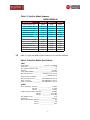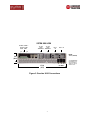
1
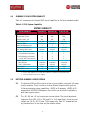
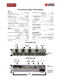
Price: $25.00
OPERATING MANUAL
X100 COMPACT, INTEGRATED
DC POWER SYSTEM
Manual No. X100-203-1
X100-Man-revA-11-26-03.p65
© copyright 2003 UNIPOWER Corp.
All Rights Reserved
UNIPOWER Telecom, Division of UNIPOWER Corporation
2633065, UNITED STATES • Tel: 954-346-2442 • Fax: 954-340-7901 • [email protected]
DIV. OF UNIPOWER CORP. • 3900 Coral Ridge Drive, Coral Springs, Florida
UNIPOWER EUROPE • Parkland Business Centre, Chartwell Road, Lancing, BN15 8UE, ENGLAND • Tel: +44(0)1903 768200 • Fax: +44(0)1903 764540 • [email protected]
ILLUSTRATIONS
FIGURE
1
2
3
4
5
TITLE
PAGE
Gravitas X100 Compact, Integrated DC Power System
Gravitas X100 with Connections
Gravitas X100 Integral Controller
Gravitas X100 Simplified Block Diagram
Gravitas X100 Signal Interface Connections
27
2
7
9
9
13
CONTENTS
SECTION
TOPIC
PAGE
1.0
2.0
3.0
4.0
5.0
6.0
7.0
Introduction
General Description
Gravitas X100 Summary Features
Summary of X100 System Capability
Rectifier Summary and Specifications
Power Distribution Section
Controller Section
8.0
9.0
Safety Warnings and Precautions
Warranty
10
10
Unpacking and Inspection
Description of Operation
Installation
Introduction to Control and Monitoring
Integral Controller Front Panel Description
Signal Input/Output Connections
Integral Controller LED Indicators
Front Panel Adjustment Potentiometers
Description of Controller Operation
Controller Signal Connections
Battery Temperature Compensation (Option)
Alarm Enabling
Voltage and Current Measurements
Maintenance
Gravitas X100 Data Sheet
11
11
12
15
15
16
16
16
17
18
20
21
21
21
A1
10.0
11.0
12.0
13.0
14.0
15.0
16.0
17.0
18.0
19.0
20.0
21.0
22.0
23.0
Appendix 1
28
1
1
3
4
4
6
8
OPERATING MANUAL
GRAVITAS X100 COMPACT,
INTEGRATED DC POWER SYSTEM
1.0
INTRODUCTION
This Operating Manual should be read through carefully before installing and operating
the Gravitas X100 Integrated DC Power System.
Connection to this system and servicing it must be performed only by qualified
technicians who are trained in the installation and operation of electrical power
systems. The safety warning described later must be carefully followed.
Unipower Telecom, a division of Unipower Corporation, does not accept responsibility
for safety, reliability or performance of these systems if any modifications or repairs are
carried out by unauthorized personnel. Unipower Telecom specified replacement parts
must be used and must be of the same type and rating to ensure continued protection
against risk of fire.
Since Unipower Telecom has a policy of continued product improvement, specifications
and components of this system are subject to change.
2.0
GENERAL DESCRIPTION
2.1
The Gravitas X100 is a compact, integrated DC power system. See Figure
1. It consists of three high power-density, hot-swap rectifier modules
which can produce a total 60 amperes at -48VDC, 99 amperes at +24VDC,
or +12V at 100A depending on system configuration. In a 2+1 redundant
operation the output currents are 40, 66 and 50 amperes, respectively.
There are three standard models of the X100.
2.2
The complete system has a DC distribution panel with up to 5 load circuits which are protected by circuit breakers, GMT fuses or a combination
of the two. Optional is a low-voltage battery disconnect. Battery breakers
for up to two battery strings can be provided.
1
SYSTEM FRONT VIEW
æ
æ
æ
1
1
3
2
2
4
GMT
FUSES
CONTROLLER
SECTION
æ
æ
DC LOAD
BREAKERS
æ
BATTERY
STRING
BREAKER(S)
1
4
æ
2RU
æ
1
2
3
Figure 1. Gravitas X100 Compact, Integrated DC Power System
2
RECTIFIER
MODULES
3.0
2.3
The integral controller has LED visual alarms, Form C relay alarms, test
points and set-point adjustments including over- and under-voltage
adjustments. There is a temperature compensation option.
2.4
The complete Gravitas X100 is only 2RU high (3.47 inches or 88.1mm)
and is easily installed by a qualified technician. All connections are at the
rear to DIN-rail terminal blocks. The units may be mounted in 19- or
23-inch racks. See Figure 2.
GRAVITAS X100 SUMMARY FEATURES
u
u
u
u
u
u
u
u
u
u
u
u
u
u
u
u
Choice of Hot-Swap Rectifiers
120 or 230VAC Input
Power Factor Corrected
Class B EMI Input Filter
Up to 60A at -48VDC
Up to 99A at +24VDC
Up to 100A at +12VDC
Up to 4 DC Circuit Breakers plus GMT Fuses
Up to 2 Battery Strings
Up to 2 Battery String Breakers
LV Battery Disconnect Option
Integral Controller
Quick, Easy Installation
Modular Design
Only 2RU (3.47 Inches) High
Only 11.56 Inches (294mm) Deep
3
4.0
SUMMARY OF X100 SYSTEM CAPABILITY
Table 4-1 summarizes the Gravitas X100 overall capability for the three standard models.
Table 4-1 X100 System Capability
SYSTEM CAPABILITY
SYSTEM CAPABILITY
System Voltage
System Max. Current
System Current, 2+1
Input Range, VAC
Rectifier Model
Rectifiers Required, max.
Battery String Breakers
Low Voltage Disconnect1
Total No. of DC Loads, max.2
1A-50A Breakers (standard)
1A-20A Breakers (standard)
½A-12A GMT Fuses (option)
Control Features
Alarm Outputs
Temp. Compensation
Rack Height
Rack Width, Inches3
NOTES:
5.0
X100-48P/60
X100-24P/100
X100-12P/100
-54.4VDC
60A
40A
85-264
RPCP48/20
3
1 standard
optional
5
2
2
4
+27.2VDC
99A
66A
85-264
RPCP24/33
3
2 standard
optional
5
2
2
4
+13.6VDC
100A
50A
85-264
RPCP12/50
2
2 standard
optional
5
2
2
4
4 standard
optional
2RU
19
4 standard
optional
2RU
19
4 standard
optional
2RU
19
1. Battery disconnect.
2. Up to 4 loads standard. Up to 5 loads with combination of breakers and optional GMT fuses.
3. 23-Inch mounting brackets can be supplied.
RECTIFIER SUMMARY & SPECIFICATIONS
5.1
The Gravitas X100 rectifiers consist of two or three parallel-connected, hot-swap
rectifier modules. There is a choice of three different modules which give the
following maximum system capabilities: -48VDC at 60 amperes, +24VDC at 99
amperes and +12VDC at 100amperes. One rectifier can be used for redundancy
with lower system output.
5.2
The -48, +24 and +12 volt outputs are nominal values. The actual adjustment
ranges are 45 to 58V, 22.5 to 29V, and 11 to 14.5 respectively; the factory-set
outputs are -54.4V, +27.2V, amd 13.6V respectively. Table 5-1 summarizes the
key characteristics of the three rectifier module models.
4
Table 5-1 Rectifier Module Summary
MODULE MODEL NO.
SPECIFICATIONS
Output Voltage, Nom.
Output Voltage, Set
Output Voltage Range
Output Current, Max.
Output Watts, Max.
Input Range, VAC
Input Power Factor
Input Current, 230VAC
120VAC
Inrush Current Limit
Input Frequency, Hz
Efficiency
Total Regulation, Max.
5.3
RPCP48/20 RPCP24/33 RPCP12/50
48VDC
24VDC
12VDC
54.4V
27.2V
13.6V
45-58V
22.5-29V
11-14.5V
20A
33A
50A
1,088
898
680
85-264
85-264
85-264
0.99
0.99
0.99
5.6A
5.6A
5.6A
10.8A
10.8A
10.8A
50A Pk.
50A Pk.
50A Pk.
47-63
47-63
47-63
87%
85%
82%
2.0%
2.0%
2.0%
Table 5-2 gives the detailed specifications of the rectifier modules.
Table 5-2 Rectifier Module Specifications
INPUT
Voltage Range _______________________ 85-264 or 170-264VAC
Power Factor _______________________________________ 0.99
Total Harmonic Distortion, Max. _________________________ 5%
Frequency _______________________________________ 47-63Hz
Inrush Current Limiting ___________________________ 50A Peak
EMI Filter, Conducted ______________ FCC20780 pt. 15J Curve B
_____________________ EN55022 Curve B
Input Immunity, Conducted
Fast Transients, Line-Line _________ ±2kV (EN61000-4-4 Level 3)
Surges, Line-Line ________________ ±1kV (EN61000-4-5 Level 2)
Surges, Line-Ground _____________ ±2kV (EN61000-4-5 Level 3)
OUTPUT
Output Voltage Set, 48V Nom. _____________________ 54.4VDC
24V Nom. _____________________ 27.2VDC
12V Nom. _____________________ 13.6VDC
Voltage Adjustment Range, 48V Nom. ______________ 45-58VDC
24V Nom. _____________ 22.5-29VDC
12V Nom. _____________ 11-14.5VDC
Total Regualtion, Max. ______________________________ 1.0%
Holdup Time ____________________________________ 20msec.
Overvoltage Protection, 48V Out _______________________ 58V
24V Out _______________________ 29V
12V Out ______________________ 14.5V
5
Filtering: Wideband Noise, 20Mhz BW
48V Out, P-P __________________________________ 500mV
24V Out, P-P __________________________________ 250mV
12V Out, P-P __________________________________ 125mV
Voice Band Noise ______________________________ <32dBrnC
Current Limit __________________________ 105% Rated Current
Efficiency _______________________________________ 82-87%
STATUS INDICATORS
AC Good ______________________________________ Green LED
DC Good ______________________________________ Green LED
ENVIRONMENTAL
Operating Temp. Range ________________________ 00C to +700C
Output Current Derating ______________ 2.5%/0C, 500C to 700C
Storage Temp. Range _______________________ -400C to + 850C
Humidity _______________________ 0% to 95%, Non-Condensing
ESD _________________ Bellcore GR-1089-Core and EN61000-4-2
Cooling ____________________________________ Internal Fans
6.0
POWER DISTRIBUTION SECTION
6.1
Figure 1 shows the top section of the system showing two battery circuit breakers (one standard in the 48V model, two standard on the 24 and 12V models).
These battery breakers are rated at 80A each. Next are up to two load breakers
rated 1A to 50A in positions 1 and 2 followed by two additional load breakers
rated at 1A and 20A in postions 3 and 4. An optional 4 (active) position GMT
fuse block rated up to 15A each.
6.2
The total number of DC load circuits is five. This means any combination of up to
five breakers and fuses are available.
6.3
The DC distribution connections are made at the rear of the X100 to DIN-Rail
terminal blocks. See Figure 2.
6
SYSTEM REAR VIEW
æ
æ
J2
BAT 2
IN
BAT 1 IN
æ
æ
J1
æ
1A-20A
1A-50A
LOAD
LOAD
TERMINALS TERMINALS
æ
ALARMS, FORM C
OUTPUTS AND
TEMP. COMP.
DEPTH:
11.56 (294mm)
3.47
(88.1)
ALL DIMENSIONS
IN INCHES (mm).
All specifications
subject to change
without notice.
æ
æ
Figure 2. Gravitas X100 Connections
7
æ
3
2 1
AC INPUT
17.19
(437)
7.0
CONTROLLER SECTION
7.1
Integral Controller. This controller controls the system rectifier, monitors the
system parameters and has alarms for system failures. See Figure 3. There are
eight red LED alarms and four Form C relay outputs to indicate a failure:
◆
◆
◆
◆
◆
◆
◆
◆
Rectifier-Fail
Rectifier-Major
Rectifier-Minor
AC Input
Circuit Breaker or Fuse
Low Voltage Disconnect
Overvoltage
Undervoltage
Four front-panel voltage-set adjustments are for:
◆ Float Voltage
◆ Battery Overvoltage
◆ Battery Undervoltage
◆ Temperature Compensation
Test points for load voltage and current permit external measurement of these
values.
7.2
Low-Voltage Battery Disconnect (Option). This battery disconnect has a
100-ampere capacity and connects between the rectifier output bus and the
battery. The contactor disconnects the battery from the rectifier and loads when
the rectifier bus (and battery) voltage drops to 42.5V for a 48V system, 21.25V
for 24V system or 10.6V for a 12V system. When the rectifier bus voltage rises
above 49V for a 48V system, 24.5V for a 24V system, or 12.3V for a 12V system,
the contactor reconnects the battery to the rectifier bus.
8
Figure 3. Integral Controller
Figure 4. Gravitas X100 Simplified Block Diagram
9
8.0
9.0
SAFETY WARNINGS AND PRECAUTIONS
8.1
This Integrated Power System must be handled, installed and maintained only by
qualified technical persons who are trained in the installation and use of power
systems and are well aware of the hazards involved with these systems.
8.2
WARNING: This power system has hazardous external and internal voltages;
the system also has high earth leakage current. The AC input voltage of 85
to 264VACis hazardous, and the output voltages of 45 to 58VDC, 22.5 to
29VDC and 11 to 14.5VDC are hazardous. Touching either input or output
terminals while the system is connected and operating could cause serious
injury or death. Internal assemblies are also hazardous and should not be
touched.
8.3
Covers on internal assemblies should not be removed. There are no user-serviceable components in these assemblies. Removing the covers of these assemblies
will void the warranty.
8.4
Installation connections should be made without input power applied, without
battery power applied and without other power sources applied to the load.
8.5
The chassis should be connected to the system frame ground terminal and a
three-wire AC power line with ground connection should be used to minimize
electrical shock hazard and ensure low EMI (electromagnetic interference).
8.6
This operating manual should be read carefully and understood before attempting
installation or testing.
WARRANTY
All products of UNIPOWER Telecom, a division of UNIPOWER Corporation, are warranted for two (2) years
from date of shipment against defects in material and workmanship. This warranty does not extend to
products which have been opened, altered or repaired by persons other than persons authorized by the
manufacturer or to products which become defective due to acts of God, negligence or the failure of
customer to fully follow instructions with respect to installation, application or maintenance. This
warranty is extended directly by the manufacturer to the buyer and is the sole warranty applicable.
EXCEPT FOR THE FOREGOING EXPRESS WARRANTY, THE MANUFACTURER MAKES NO WARRANTY, EXPRESS OR
IMPLIED, INCLUDING, BUT NOT LIMITED TO, THE WARRANTY OF MERCHANTABILITY OR FITNESS FOR A
PARTICULAR PURPOSE. As the sole and exclusive remedy under this warranty, the manufacturer, at its
option, may repair or replace the non-conforming product or issue credit, provided the manufacturer’s
inspection establishes the existence of a defect. To exercise this remedy, the buyer must contact the
manufacturer’s Customer Service Department to obtain a Return Material Authorization number and
shipping instructions. Products returned without prior authorization will be returned to buyer. All
products returned for repair must be shipped freight prepaid to UNIPOWER. If the buyer fails to fully
comply with the foregoing, the buyer agrees that no other remedy (including, but not limited to,
incidental or consequential damages for lost profits, lost sales, injury to person or property or any other
incidental or consequential losses) shall be available to the buyer.
10
10.0
11.0
UNPACKING AND INSPECTION
10.1
This Gravitas X100 Integrated DC Power System was carefully tested, inspected
and packaged for shipment from our factory. Upon receipt of the unit it should
be carefully unpacked and inspected for any damage in shipment.
10.2
If there is evidence of damage, do not attempt to install the unit. The freight
carrier should be notified immediately and a claim for the cost of the system
should be filed with the carrier for direct reimbursement. Be sure to include the
model and serial number of the damaged unit in all correspondence with the
freight carrier. Also save the shipping carton and packing material as evidence of
damage for the freight carrier’s inspection.
10.3
UNIPOWER Telecom will cooperate fully in case of any shipping damage investigation.
10.4
Always save the packing materials for later use in shipping the unit. Never ship
the rectifier system without proper packing.
DESCRIPTION OF OPERATION
11.1
Block Diagram. A simplified block diagram of the Gravitas X100 is shown in
Figure 4.
11.2
Operation. The AC input of 120 or 230VAC (Fig. 4) goes to each rectifier
through individual IFC line card entries. Optional terminal block are GMT filtered
out are avaialble. The input of each module has power factor correction resulting
in a pure factor near unity. The outputs of the modules are connected in parallel
with an ORing diode in the output of each rectifier. This allows rectifier module
to be hot-swapped without disturbing the output voltage.
The -48, +24VDC or +12VDC output goes through the LVD contactor and the
battery circuit breaker to the battery. The output also goes to the load circuit
breakers and then to each load. If the rectifier bus voltage drops below 42.5VDC
for a -48 system or 21.25VDC for a +24V system, and 10.6VDC for a +12V system.
the LVD contactor opens and disconnects the battery from the system output.
This generally happens when there is a failure in the AC input to the rectifiers.
When AC input is restored and the rectifier bus voltage rises above 49.0VDC for a
-48V system, 24.5VDC for a +24V system, and 12.3VDC for a +12V system the
LVD contactor closes again.
11
11.3
12.0
Control and Monitoring. The integral controller has inputs from and outputs to
each rectifier module. The inputs let the controller monitor the operation of each
rectifier module and detect failure if it occurs. The outputs to the rectifier
modules let the controller control the module output voltage. Likewise, there is
an input and output from the Low Voltage Disconnect (LVD), an input from the
battery and an input from each load breaker. These signals result in operation of
the alarm LEDs and the Form C relay alarms. The controller also has digital meters
to read the load voltage and current. A 50mV shunt is located in the rectifier bus
to measure the load current.
INSTALLATION
12.1
CAUTION: Re-read the Safety Warnings and Precautions in Section 8.0. All
power should be OFF for the input and output loads before making connections. Connection of the X100 chassis to frame ground should be made
first. If the X100 has been turned on before installation connections, it
should be turned off and given a 5-minute waiting period for all internal
energy storage capacitors to be discharged.
12.2
Input AC Power Connection. See Figure 2. An unplugged 3-wire AC power line
should be connected into the input terminal blocks or plug IEC connectors. The
line, neutral and ground connections should be carefully followed when making
the AC connections. The AC line cable should be sized to safely carry 20 amperes
AC.
12.3
Checking Outputs. Turn all output circuit breakers to the OFF position and/or
remove all fuses from the GMT fuse-holder. With no loads connected and without
the battery connected, plug in or connect the AC input cable to the power
source. Be sure to use the correct AC voltage for the rectifier inputs. Observe the
DC voltage reading on the test points on the controller panel. The voltage should
be approximately 54.4, 27.2, or 13.6VDC (depending on model), which is the
factory setting. The current test points should read zero. One by one, turn each
output circuit breaker to the ON position and/or insert a GMT fuse and, using a
digital voltmeter, measure the DC voltage across the corresponding output
terminals. The voltage should again read approximately 54.4, 27.2, or 13.6 volts.
After each output is measured, turn OFF that circuit breaker and/or remove the
GMT fuse and turn ON and/or insert fuse in the next one. After measuring the
last circuit, turn off that breaker and/or remove the GMT fuse and make sure
that all output breakers are in the OFF position and/or all fuses are removed.
Next, unplug or disconnect the AC input power source. Before touching any
terminals wait 5 minutes for the internal storage capacitors to discharge.
12
INTERFACE CONNECTIONS
J2
J1
PIN
FUNCTION
1
2
3
4
5
6
7
8
9
10
11
12
MINA - NC
MINA - C
MINA - NO
MAJA - NC
MAJA - C
MAJA - NO
ACFA - NC
ACFA - C
ACFA - NO
RFA - NC
RFA - C
RFA - NO
PIN
FUNCTION
1
2
3
4
5
6
7
8
9
10
11
12
DESCRIPTION
Minor Alarm Output - NC
Minor Alarm Output - C
Minor Alarm Output - NO
Major Alarm Output - NC
Major Alarm Output - C
Major Alarm Output - NO
AC Fail Alarm Output - NC
AC Fail Alarm Output - C
AC Fail Alarm Output - NO
Rectifier Fail Alarm Output - NC
Rectifier Fail Alarm Output - C
Rectifier Fail Alarm Output - NO
DESCRIPTION
—
—
—
TCEN
—
TC(+)
—
TC(-)
—
RVADJ
—
S(-)
Temperature Compensation Alarm Disable Input
Temperature Compensation Probe (+) Input
Temperature Compensation Probe (-) Input
System Remote Voltage Adjust Input
Control Common Output
Figure 5. Gravitas X100 Signal Interface Connections
13
12.4
Controller Section Operation and Settings. At this point, before the final
installation connections, read sections 13 through 21, covering the Control Panel
operation. Next, go back to sections 19, 20 and 21 and make the signal connections, controller adjustments, temperature compensation adjustment and alarm
enabling settings.
WARNING: Remember to take precautions each time the system is turned
on and also when connecting or disconnecting the battery. Remember that
the battery has a hazardous voltage at its terminals. Also remember to
allow 5 minutes for internal capacitors to discharge after disconnecting
the AC input power and the battery.
12.5
Connection to Loads. With input AC power unplugged, the battery disconnected
and no other power sources connected to the loads, make sure that all load
circuit breakers are set to the OFF position and/or all GMT fuses are removed.
See Figures 2 and 4. Connect load wires to each set of output terminals, one at a
time. Note that the front panel breaker and fuse numbers directly correspond to
the output terminal numbers. Be sure to connect the polarities correctly as
shown in Figure 4.
12.6
Connection to Battery. With AC input unplugged, remove the three rectifier
modules from the system chassis. Make sure all load circuit breakers are in the
OFF position and/or all GMT fuses removed. Set the battery circuit breaker to the
OFF position. Carefully connect the battery cables to the DIN-Rail battery terminals shown in Figure 2. while observing the correct polarity.
WARNING: Improper polarity of the battery connection may damage the
power system. Take precautions when installing the battery and note that
the battery cables are “hot” (live).
Set the battery circuit breaker to the ON position and observe the reading on the
digital voltmeter on the controller panel or connected to the test points. It
should indicate the voltage of the battery, approximately 48, 24, and 12VDC
when charged. If the battery is connected with wrong polarity, there will be no
reading on the test points.
14
12.7
System Turn-On. Perform the following operations:
◆
◆
◆
◆
◆
◆
◆
Put the battery circuit breaker in the OFF position
Plug in the three rectifier modules
Connect the AC power cable to the AC source
Put the battery circuit breaker in the ON position
Check the digital voltmeter reading for the correct voltage
Set each load circuit breaker to the ON position and/or insert each fuse
Note the reading on the controller panel test points. With all loads
connected, the output current should not exceed rated system load
for non-redundant operation.
13.0 INTRODUCTION TO CONTROL & MONITORING
13.1 The integral controller is a basic control and monitoring system for the
X100 power system. It controls up to 3 rectifiers, precisely setting the
float voltage on all rectifiers simultaneously. It monitors the battery
voltage and current by means of front panel test points. See Figure 3.
13.2
Front panel LEDs indicate status and alarm conditions of the monitored
functions. Front panel potentiometers permit easy adjustment of the
various control voltages. Form C relays also indicate status and alarms.
14.0 INTEGRAL CONTROLLER FRONT PANEL DESCRIPTION
14.1 The panel has a green LED alarm CTR which is normally green but turns
off upon failure of the Control and Monitor System.
14.2
The controller has four terminals V+, V-, I+, I- for reading amperes and
volts, the load current and voltage, using external meters. The current
test points use an internal 50mV shunt. See Figure 3.
14.3
Voltage adjustment potentiometers VF, OV, UV, and TC. See the definitions
in section 17.0.
14.4
Finally, are the LED indicators: LVDA, FA, OVUVA, TCA, MAJA, RFA, MINA, and
ACFA. See the definitions in section 16.0.
15
15.0
SIGNAL INPUT/OUTPUT CONNECTIONS
See Figure 5. for location and description of input and output signals, including the
alarm enable switches. The input and output signal connections are to spring-clamp
terminal blocks.
16.0
INTEGRAL CONTROLLER LED INDICATORS
Red LEDs. (Normally off, failure is red) These are failure alarms indicating the following:
◆
◆
◆
◆
◆
◆
◆
◆
17.0
LVDA: Low Voltage Disconnect Alarm
FA: Failure on any circuit breaker or fuse in the DC distribution
OVUVA: Battery Overvoltage or Undervoltage
TCA: Temperature Compensation Alarm
MAJA: Major Alarm
RFA: Rectifier Fail Alarm
MINA: Minor Alarm
ACFA: AC Fail Alarm
FRONT PANEL ADJUSTMENT POTENTIOMETERS
There are four front panel adjustment potentiometers:
◆
◆
◆
◆
VF:
OV:
UV:
TC:
Float Voltage set (12 turns)
Battery Overvoltage set (single turn)
Battery Undervoltage set (single turn)
Temperature Compensation set (single turn)
Note that Temperature Compensation is an option.
16
18.0
DESCRIPTION OF CONTROLLER OPERATION
18.1
The system controls and monitors up to three rectifier modules. This is accomplished by means of a control cable which connects between the rectifier section
and controller. Through these connections the controller controls the rectifier
output voltage which is preset by the VF (float voltage) adjustment
potentiometer.
18.2
The Controller also monitors the AC input and DC output of each of the
rectifiers and gives an LED warning and Form C relay contact alarm in case of
failure of any one or more of the rectifier modules.
18.3
The Controller also monitors for alarms from the low voltage disconnect and
circuit breaker panel. The alarm outputs are Form C relay contacts which can be
used for remote or local system alarms.
18.4
Other alarm outputs are for battery overvoltage and battery undervoltage. These
are also Form C relay contacts.
18.5
Battery voltage and current are also monitored by the controller. They are read
by the front panel test points. When using the front panel test points with an
external voltmeter, the system output voltage is read directly from the voltage
test points. The current, however, is read as the voltage across the current test
points which go to a 50mV shunt. A 50mV shunt voltage corresponds to 100
amperes which is the full scale current. This results in a voltage scale factor of 2
amperes per millivolt.
18.6
The controller initiates a Form C alarm when any one or more circuit breakers
have tripped or GMT fuses have blown.
18.7
The controller senses the battery voltage and provides LVD (low voltage disconnect) drop-out and pick-up drive for the LVD contactor.
17
19.0
CONTROLLER SIGNAL CONNECTIONS
19.1
See Figure 5. Signal connections to the J1 and J2 spring-clamp terminal blocks
should to be made with wire gauges no. 20-26 AWG. Insulation should be
stripped 0.2” from wire end.
Alarm signals are Form C relay contact alarms for the function given. “Normally
Closed” (NC) means a “short” between this terminal and the Common (C) terminal when the function is operating properly with power applied. “Normally Open”
(NO) means an “open” between this terminal and the Common (C) terminal when
the function is operating properly with power applied.
19.2
Form C Alarm Outputs.
ACRONYM
RFA
ACFA
MINA
MAJA
19.3
DESCRIPTION
Rectifier Fail Alarm
AC Fail Alarm
Minor Alarm
Major Alarm
Alarm and Signal Setup.
19.31 General. All signals are preset at the factory, and these values are listed
in the following sections. Where voltages are given, the first one is for a
-48VDC system, the second for a +24V system, and the third for +12V
system.
19.32 LVD Dropout and Pickup. The Low-Voltage Disconnect (LVD) is an
option. The trip levels are factory set at -42.5, +21.25, or +10.6VDC
dropout and -49.0, +24.5, or 12.3VDC pickup. These are not field
adjustable.
19.33 Battery Float Voltage. The voltage is set at the factory at -54.4,
+27.2 or +13.6VDC. If a different nominal value is required,
do the following:
Install all rectifiers in the system.
Disconnect the battery and adjust the float voltage (VFL)
potentiometer on front panel to the level required. Do not use the
voltage adjustments on the front panel of the rectifier modules.
◆ Reconnect the battery.
◆
◆
18
19.34 Battery Overvoltage. The voltage across the battery where the
overvoltage alarm trips is factory set at -57, +28.6, or +14.3VDC. If a
different nominal value is required, do the following:
◆
◆
◆
◆
◆
◆
◆
Unplug all rectifiers, disconnect AC, disconnect all loads and the
battery.
With an external variable voltage supply rated 0-60VDC, connect
it across one set of the output load terminals and turn on its
associated circuit breaker on the front panel. Be sure to observe the
correct polarity.
Bring the voltage up to approximately -55V, +27.5 or +13.3VDC.
Verify that alarm LED (OVUVA) is off.
Verify that the alarm LED goes on when the voltage is adjusted to
-57.1VDC ± 1%, +28.5VDC ± 1% or +14.3VDC ± 1%.
Readjust the 0V potentiometer on the front panel to set at the
desired level.
Verify that the alarm LED goes red at the set point.
19.35 Battery Undervoltage. The voltage across the battery where the
undervoltage alarm trips is factory set at -43.5VDC, +21.8VDC or
+ 10.9VDC. If a different value is required, do the following:
◆
◆
◆
◆
◆
Follow the same procedure as described above for overvoltage
alarm setup.
At -55V, +27.5V, or +13.8V verify the alarm LED (OVUVA) is off.
It should turn red when the voltage is adjusted to -43.5 ± 1%,
+21.8VDC ± 1%, or +10.9VDC ± 1%
Readjust the UV potentiometer on the front panel to set at the
desired level.
Verify that the alarm LED goes red at the set point.
19.36 TC Input. This is the optional temperature compensation input from
the temperature compensation probe that comes with this option. The
probe is used to measure battery temperature which is used to control
the output of the rectifier. There is no polarity reference for connecting
the temperature probe. Connection of the probe is to pins 6 and 8 of
J1. See Figure 4. See Section 20 for further details on temperature
compensation.
19
20.0
BATTERY TEMPERATURE COMPENSATION (OPTION)
20.1
The temperature compensation option comes with a temperature probe and 20foot cable. The probe is a thermistor which is connected to J1 pins 6 and 8.
There is no polarity for this connection. The probe is used to monitor the temperature of the battery and adjust the rectifier output voltage accordingly. As
battery temperature increases, rectifier output voltage decreases.
20.2
The change in output voltage with temperature is -3.75mV/0C per battery cell,
centered at 250C. For example, for a +100C temperature change from 250C with
the rectifier charging a 48V battery, the change in the rectifier output voltage
would be:
48
= 24 cells
2
V = 24 cells x 100C change x (-3.75mV/0C) = -900mV = -0.9V
20.3
The probe can be located in several possible places: right on the battery to
detect the battery temperature, near the battery in free air to detect the local
ambient temperature, or on the power plant metal frame near the battery.
20.4
If the TC probe is either opened or shorted, the rectifier outputs revert to the
float voltage.
20.5
Setting the Temperature Compensation Voltage.
20.51 Make sure that the float voltage was set with the temperature probe
disconnected.
20.52 Before connecting the temperature probe, record the float voltage to
three digits.
20.53 Connect the temperature probe to terminals 6 and 8 of J1.
20.54 With the temperature probe at approximately 250C ambient temperature,
adjust the front panel TC potentiometer until the rectifier output voltage
as read on an external voltmeter is exactly the same as the previously
recorded float voltage.
20
21.0
ALARM ENABLING
21.1
There is only one alarm function that requires enable:
◆
21.2
22.0
23.0
TC Enable (TCEN): Remove jumper from J1 Pin 4 to J1 Pin 6 to enable
the TC function.
After making the signal connections, controller adjustments, temperature compensation adjustment and alarm enable settings of Sections 19 through 21, go
back to Section 12.5 to continue the installation procedure.
VOLTAGE AND CURRENT MEASUREMENTS
22.1
Voltage. The V+ and V- test points on the right front panel permit direct external measurement of the battery voltage.
22.2
Current. The I+ and I- test points permit direct external measurement of the
load current. A voltmeter across these test points gives a reading of 2 amperes
per millivolt.
MAINTENANCE
No routine maintenance is required on the Gravitas X100 power system except for
periodic cleaning of dust and dirt around the rectifier module fans and ventilation holes.
A small vacuum nozzle should be used for this.
21
ULTRA COMPACT, 48V, 24V and 12V
INTEGRATED DC POWER SYSTEMS
æ
2RU
æ
GRAVITAS X100
DESCRIPTION
LVD73/23/EEC
KEY FEATURES
u
u
u
u
u
u
u
u
u
u
u
Compact, 2RU High
Fully Integrated System
Hot-Swap Rectifier Modules
Integrated Controller
100A at +13.6VDC
99A at +27.2VDC
60A at -54.4VDC
Pluggable Circuit Breakers
Quick-Connect Terminals
Wide Range AC Input
Less Than 12-Inches (305mm)
Depth
SAFETY CERTIFICATIONS
AGENCY
UL
CUL
DEMKO
STANDARD
UL1950
CSA22.2, No. 950
EN60950
Gravitas X100 is an ultra-compact, integrated, DC power
system. It consists of up to three high power-density, hotswap rectifier modules which can produce 60 amperes at
-54.4VDC, 99 amperes at +27.2VDC and two rectifiers for
100A at +13.6VDC. In 2+1 redundant operation the output
current is 40 amperes or 66 amperes, respectively for
-54.4VDC & 24.72VDC, or 50 amperes for +13.6VDC.
The system has a DC distribution panel with up to 5 load
circuits which are protected by circuit breakers (standard)
and GMT fuses (option). A battery breaker is standard and
a low-voltage battery disconnect is optional.
The integral controller has LED visual alarms, Form C relay
alarms, test points and set-point adjustments including
over- and under-voltage adjustments. There is also a
temperature compensation option.
The complete Gravitas X100 is only 2RU high (3.47 inches
or 88.1mm) and is easily installed by a qualified technician. All power connections are at the rear of the unit to
DIN-rail terminal blocks. A comprehensive operating manual
explains all the details of operation and installation. The
units may be mounted in 19- or 23-inch racks.
PLUGGABLE
CIRCUIT
BREAKERS
TWO-YEAR WARRANTY
A1
22
www.unipowertelecom.com
GRAVITAS X100 SUMMARY FEATURES
u
u
u
u
u
u
u
u
u
-48, +24, or +12VDC Hot-Swap Rectifiers
120 or 230VAC Input
Power Factor Corrected
Pluggable Circuit Breakers
Class B EMI Input Filter
Up to 60A at -54.4VDC
Up to 99A at +27.2VDC
Up to 100A at +13.6VDC
2+1 Redundant Operation
SYSTEM CAPABILITY
SYSTEM CAPABILITY
System Voltage
System Max. Current
System Current, 2+1
Input Range, VAC
Rectifier Model
Rectifiers Required, max.
Battery String Breakers
Low Voltage Disconnect1
Total No. of DC Loads, max.2
1A-50A Breakers (standard)
1A-20A Breakers (standard)
½A-12A GMT Fuses (option)
Control Features
Alarm Outputs
Temp. Compensation
Rack Height
Rack Width, Inches3
NOTES:
X100-48P/60
X100-24P/100
X100-12P/100
-54.4VDC
60A
40A
85-264
RPCP48/20
3
1 standard
optional
5
2
2
4
+27.2VDC
99A
66A
85-264
RPCP24/33
3
2 standard
optional
5
2
2
4
+13.6VDC
100A
50A
85-264
RPCP12/50
2
2 standard
optional
5
2
2
4
4 standard
optional
2RU
19
4 standard
optional
2RU
19
4 standard
optional
2RU
19
1. Battery disconnect.
2. Up to 4 loads standard. Up to 5 loads with combination of
breakers
and optional GMT fuses.
3. 23-Inch mounting brackets can be supplied.
INTEGRAL CONTROLLER
This controller controls the system rectifier, monitors the system parameters and has alarms
for system failures. There are eight red LED alarms which indicate a failure: Major Alarm, Minor
Alarm, Fuse or Breaker Alarm, Overvoltage or Undervoltage Alarm, Temperature Compensation
Alarm, Rectifier Failure Alarm, and AC Input Failure Alarm.
Four Form C relay outputs give alarms: Major Alarm, Minor Alarm, Rectifier Failure Alarm and AC
Input Failure Alarm. Four front-panel voltage-set adjustments are for Float Voltage, Battery
Overvoltage, Battery Undervoltage and Temperature Compensation. Test points for load voltage and current permit external measurement of these values. An option for this controller
includes a temperature compensated output from the rectifier.
23
RPCP RECTIFIER MODULE SPECIFICATIONS
INPUT
Voltage Range _________________________ 85-264VAC
Power Factor _______________________________ 0.99
Total Harmonic Distortion, Max. _________________ 5%
Frequency _______________________________ 47-63Hz
Inrush Current Limiting ___________________ 50A Peak
EMI Filter, Conducted ______ FCC20780 pt. 15J Curve B
______________ EN55022 Curve B
Input Current, 230VAC ______________________ 5.6A
120VAC ______________________ 10.8A
Input Immunity, Conducted
Fast Transients, Line-Line ±2kV (EN61000-4-4 Level 3)
Surges, Line-Line ______ ±2kV (EN61000-4-5 Level 3)
Surges, Line-Ground ____ ±4kV (EN61000-4-5 Level 4)
Overvoltage Protection, 48V Nominal ___________ 59V
24V Nominal ____________ 29V
12V Nominal ___________ 14.5V
Filtering: Wideband Noise, 20Mhz BW,
48V Nominal, P-P ______________________ 500mV
24V Nominal, P-P ______________________ 250mV
12V Nomial, P-P _______________________ 125mV
Voice Band Noise ______________________ <32dBrnC
Current Limit __________________ 105% Rated Current
Efficiency _______________________________ 82-87%
SAFETY STANDARDS
UL 1950, CSA22.2-950, EN60950
STATUS INDICATORS
OUTPUT
AC Good ______________________________ Green LED
DC Good ______________________________ Green LED
Current & Voltage, 48V Nominal ________ [email protected]
24V Nominal _______ [email protected]
12V Nominal _______ [email protected]
Voltage Adjustment Range, 48V Nominal ___ 45-58VDC
24V Nominal ____ 22-29VDC
12V Nominal ___ 11-14.5VDC
Output Power, Rated 48V Nominal ___________ 1,088W
24V Nominal _____________ 898W
12V Nominal _____________ 680W
Total Regulation, Max. ________________________ 2%
Holdup Time ____________________________ 20msec.
ENVIRONMENTAL
Operating Temp. Range ________________ 00C to +700C
Output Current Derating ______ 2.5%/0C, 500C to 700C
Storage Temp. Range _______________ -400C to + 850C
Humidity _______________ 0% to 95%, Non-Condensing
ESD _________ Bellcore GR-1089-Core and EN61000-4-2
Cooling ____________________________ Internal Fans
SYSTEM FRONT VIEW
æ
æ
æ
æ
1
1
3
2
2
4
GMT
FUSES
CONTROLLER
SECTION
æ
DC LOAD
BREAKERS
æ
BATTERY
STRING
BREAKER(S)
1
4
æ
2RU
æ
1
2
RECTIFIER
MODULES
3
SYSTEM REAR VIEW
æ
æ
J2
BAT 2
IN
BAT 1 IN
æ
æ
J1
æ
1A-50A
1A-20A
LOAD
LOAD
TERMINALS TERMINALS
æ
ALARMS, FORM C
OUTPUTS AND
TEMP. COMP.
DEPTH:
11.56 (294mm)
3.47
(88.1)
ALL DIMENSIONS
IN INCHES (mm).
All specifications
subject to change
without notice.
æ
æ
24
3
2
1
AC INPUT
æ
17.19
(437)
X100 CONFIGURATION GUIDE
SYSTEM
MODEL NO.
£ X100-48P/60
£ X100-24P/100
£ X100-12P/100
SYSTEM
OUTPUT, MAX.
-54.4VDC@60A
+27.2VDC@99A
+13.6VDC@100A
INPUT,
VAC
85-264VAC
85-264VAC
85-264VAC
RECTIFIER MAX. NO. OF
MODULES
MODULES
RPCP48/20
3
RPCP24/33
3
RPCP12/50
2
HOT-SWAP RECTIFIER MODULES
£ RPCP 48/20 Number Ordered _____ (Include Spares)
£ RPCP 24/33 Number Ordered _____ (Include Spares)
£ RPCP 12/50 Number Ordered _____ (Include Spares)
BATTERY PROTECTION
£ 1 Battery String Breaker (Standard for 48V System)
£ 2 Battery String Breakers (Standard for 24V and 12V System)
£ 1 Extra Battery String Breaker (Option for 48V System)
£ Low-Voltage Battery Disconnect (Option)
DC DISTRIBUTION
Up to 4 Breakers (Standard) & Up to 4 GMT Fuses (Option). Total of 5 Max.
1. Breaker ____ A (1A-50A)
2. Breaker ____ A (1A-50A)
3. Breaker ____ A (1A-20A)
4. Breaker ____ A (1A-20A)
£ GMT Fuse Block (Option). Up to 4 Fuses, 48A Max.
BREAKERS & FUSES AVAILABLE
Breakers: 1, 2.5, 5, 10, 15, 20, 25, 30, 40, & 50A
GMT Fuses: Order the number required. Maximum total current is 48A.
AMPS
0.5A
0.75
1
1.33
2
BUSSMAN NO. COLOR NO. REQ’D
GMT- ½
GMT- ¾
GMT - 1
GMT-11/3
GMT-2
Red
Brown
Gray
White
Orange
AMPS BUSSMAN NO. COLOR NO. REQ’D
3
GMT- 3
Blue
5
GMT- 5
Green
10
GMT - 10
Red-White
12
GMT- 12
Green-Yel
0
GMT-Dummy
Orange
CONTROLLER OPTION
£Temperature Compensation
BLANK COVERS (FOR UNUSED RECTIFIER SLOTS)
Cover Position:
£ 1 £ 2 £ 3 (left to right)
MOUNTING BRACKETS
£ 19-Inch
£
23-Inch
x100-revC-11-25-03.pdf
25