1
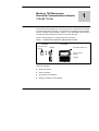
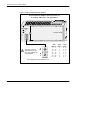
170 LNT 710 00 DeviceNet Communication Adapter for Modicon TSX Momentum User Guide 870 USE 104 00 Version 2.0 May 2002 Data, Illustrations, Alterations Data and illustrations are not binding. We reserve the right to alter products in line with our policy of continuous product development. If you have any suggestions for improvements or amendments or have found errors in this publication, please notify us by e-mail at [email protected]. Training Schneider Electric offers suitable further training on the system. Please find the nearest Schneider Electric sales office by visiting http://www.schneider-electric.com. Hotline See addresses for Technical Support Centers by visiting http://www.schneider-electric.com. Trademarks All terms used in this publication to denote Schneider Electric products are trademarks of Schneider Electric. All other terms used in this publication to denote products may be registered trademarks and/or trademarks of the corresponding corporations. Copyright All rights are reserved. No part of this document may be reproduced or transmitted in any form or by any means, electronic or mechanical, including copying, processing, or online transfer, without written permission from Schneider Electric. You are not authorized to translate this document into any other language. 2002 Schneider Electric. All rights reserved. Modicon TSX Momentum DeviceNet Communication Adapter 170 LNT 710 00 1 This Communication Adapter can be connected to any TSX Momentum I/O base to create a functional I/O module. It provides direct connection to the DeviceNet network, enabling a programmable controller or other DeviceNet master device to communicate with field devices wired to the I/O base terminals. Figure 1 shows the layout of a typical adapter and I/O base. Figure 1 Communication Adapter with TSX Momentum I/O Base Side View Communication Adapter Front View I/O Base DeviceNet network port Communication Adapter I/O Base This book describes: H Product Overview H Status Indicators H Connecting to the Network H Setting the Network Node Address 1 DeviceNet Communication Adapter 1.1 Product Overview 1.1.1 Function This adapter is installed on any TSX Momentum I/O base to form a complete I/O module that communicates on a DeviceNet network. A programmable controller or other DeviceNet master device on the network can then read from the input terminals and write to the output terminals of the I/O base. For information about the use of I/O data words in communication with I/O bases, refer to the TSX Momentum I/O Bases User Manual, part number 870 USE 002. 1.1.2 Physical Structure Each adapter connects to the internal communication connector of its I/O base. Clips lock the adapter in place, and can be released with a common screwdriver to remove the adapter. The user can fill out the front panel wiring label to identify the wiring connections and application of the I/O base terminals. 1.1.3 Network Compatibility The adapter complies with the Open DeviceNet Vendor Association (ODVA) Specification Release 2.0 for for group 2 only slave devices supporting polled and strobed connections. For a complete description of the DeviceNet network, including software operation of this device on the network, physical installation and wiring guidelines, refer to the DeviceNet specification published by ODVA. Current information about the ODVA specification can be obtained at the ODVA Web site: http://www.odva.org ODVA Vendor ID The ODVA Vendor ID number for Schneider Automation is 243 decimal. 1.1.4 Operating Voltages and Error Control Power for the adapter and I/O base is provided by the user at the field location. The adapter receives its operating voltage through its I/O base internal connection. The adapter monitors its voltage and goes offline to the network if the voltage is not within tolerance. 2 DeviceNet Communication Adapter 1.2 Specifications Table 1 General Specifications Description ODVA compliance Data rate Network power loading Required enclosure Environment, RFI, EMI Agency approval Table 2 Specification Complies with ODVA Specification Release 2.0 for group 2 only slave supporting polled and strobed connections. Supports 125/250/500 Kbaud standard DeviceNet rates. Voltage: Operational from 11 ... 25 Vdc. Current drain: 110 mA maximum, 75 mA typical. Adapter is considered open equipment, requires enclosure according to application. Adapter conforms to the specification for the I/O base upon which it is mounted. See the Momentum I/O Bases User Manual, 870 USE 002 00 for I/O base specifications. ODVA Certification UL 508, 746C, 94 CSA 22.2 No. 142 CE Mark FM Class 1 Div 2 Groups A, B, C, D Environmental Specifications Description Temperature, Operating Temperatore, Storage Humidity Altitude Vibration, Operating Reference IEC 68–2–14 IEC 68–2–14 IEC 68–2–3 MIL–STD–810 IEC 68–2–6 Shock, Operating Free Fall, Unpackaged Free Fall, Packaged IEC 68–2–27 IEC 68–2–32 IEC 68–2–32 Specification 0 ... 60_C ambient –40 ... 85_C 95% RH at 60_C non–condensing 15 000 ft 10 ... 57 Hz: 0.075 mm DA 57 ... 150 Hz: 1 g 15 g, 11 ms, 3 shocks/axis 0.1 m 24 in 3 DeviceNet Communication Adapter 1.2.1 Exec. V. 1.10 vs. V. 1.20 Exec. V. 1.20 changed the behavior of certain I/O bases if a field side fault occurred. This change affects the following bases. H H H H 170 170 170 170 ADM ADM ADM ADM 350 350 390 370 10 11 10 10 The following table describes the differences between the two versions in more detail. Refer to the TSX Momentum I/O Base User Guide (870 USE 002 00) for module specifications. Table 3 Exec. V. 1.10 vs. V. 1.20 Firmware Module Action 170 ADM 350 10 170 ADM 350 11 170 ADM 370 10 If one of the field side outputs faults (shorts out), the host will read all inputs as zeros, regardless of the input signal state. Version 1.10 170 ADM 390 10 170 ADM 350 10 170 ADM 350 11 170 ADM 370 10 If an open condition exists (unconnected) on any of the input points, the host will read all inputs as zeros, regardless of the input signal state. If one of the field side outputs faults (shorts out), the host will continue to read the inputs normally. If one of the field side outputs faults (shorts out), the host will continue to read the inputs normally. Version 1.20 170 ADM 390 10 4 If one of the field side outputs faults (shorts out), the host will read all inputs as zeros, regardless of the input signal state. If an open condition exists (unconnected) on any of the input points, the host will read H open inputs as zero (fault) and H remaining non–faulted inputs normally. DeviceNet Communication Adapter 1.3 Status Indicators The adapter has three front panel indicators showing its operating status. Figure 2 Status Indicators Power ON (Green) Pwr DeviceNet MNS IO Module/Network Status (Green/Red) NA X 10 I/O Status (Green/Red) Table 4 Power ON Indicator Indicator State Green (steady) Off Table 5 Status Normal operation: power is present from I/O base. Adapter is not receiving power from I/O base. Module/Network Status Indicator Indicator State Green (steady) Off Green (flashing) Red (steady) Red (flashing) Red/Green (flashing) Table 6 X 1 Status Normal operation: adapter is communicating on network. Adapter is not receiving power from I/O base. Adapter does not have an established network connection. Unrecoverable fault in network communication. Adapter connection to I/O base has timed out. Network access error. I/O Status Indicator Indicator State Green (steady) Off Green (flashing) Red (steady) Red (flashing) Status Normal operation: I/O is active, no faults. I/O inactive. I/O inactive, no faults. I/O has unrecoverable fault. I/O has fault. 5 DeviceNet Communication Adapter 1.4 Connecting to the Network 1.4.1 Network Connector The adapter has one 5–pin male connector for connection to the network. Its pin–to–pin spacing is 5.00 mm. A suggested mating connector is: Schneider Automation part 170 XTS 060 00. Figure 3 1.4.2 Network Connector Top View Pin Connection Wire Color 1 V– Black 2 CAN_L Blue 3 Shield –– 4 CAN_H White 5 V+ Red 1 2 3 4 5 Front Panel Network Terminator Jumper The adapter has a jumper to provide terminating impedance to the network cable. It is shipped with the jumper in the non–terminated position (pins 3 and 4). If the adapter is being installed as the last node on the network cable, move the jumper to pins 1 and 2 and mark a “X” in the box provided on the adapter’s bottom panel. Figure 4 Network Terminator Jumper Bottom Panel View Pin Rear View Termination 1/2 IN 3/4 OUT TERMINATED X OUT The adapter is shipped with the Jumper on pins 3/4. 6 If the adapter is the last node on the network cable, move the Jumper to pins 1/2, and mark an ’X’ in the TERMINATED box on the Bottom Panel. IN Circuit Board DeviceNet Communication Adapter 1.5 Setting the Network Node Address DeviceNet nodes are identified by unique addresses assigned to them by the user, in the range 0 ... 63. Duplicate addresses are not allowed. The address is assigned in a pair of rotary switches on the adapter’s front panel. The address that is set in the switches must correspond to the address defined for that adapter in the application program. This is required to ensure that messages will be transferred properly to the correct nodes across the network. Before installing the adapter, set its switches to the address that is required for your application. Default Address The adapter is shipped with the switches preset to the default address 63. How to Set the Address Before you set the switches, make sure that operating power is removed from the adapter. The switch setting is sensed when power is next applied to the adapter. Note that the adapter receives its power from the I/O base. If the adapter is already mounted on its I/O base, you must remove power to the I/O base. If you are changing the adapter’s switch setting to a new address, you must still remove all power to the adapter before setting the new address in the switches. Then reapply power to allow the adapter to sense the new setting. 7 DeviceNet Communication Adapter Figure 5 Setting the Network Node Address Do not install any adapter unless you have set its network address for your application. Pwr DeviceNet MNS IO 170 LNT 710 00 NA X 10 X 1 See your network administrator to get the node address for each adapter. X 10 X 1 This example sets the address to 31. 8 Node Upper Address Switch 0 ... 9 0 10 ... 19 1 20 ... 29 2 30 ... 39 3 40 ... 49 4 50 ... 59 5 60 ... 63 6 Lower Switch 0 ... 9 0 ... 9 0 ... 9 0 ... 9 0 ... 9 0 ... 9 0 ... 3 DeviceNet Communication Adapter 1.6 Electronic Data Sheet (EDS) Disk An Electronic Data Sheet (EDS) disk is included with this guidebook. It supplies the parameters for setup of each type of I/O base. Each file’s format on the disk complies with the ODVA specification for DeviceNet I/O module EDS parameters. README.TXT File The disk contains a README.TXT file in a standard text (ASCII) format, which can be viewed and printed with any standard word processor or text editor program. The README.TXT file describes the directory structure and filename conventions used on the EDS disk. EDS File Updates Updated EDS files are available for downloading from the Customer Support areas of the Schneider Automation Web Site and Bulletin Board service. EDS files are all contained in a “zipped” (compressed) format in a single file, named EDS.ZIP. After downloading the EDS.ZIP file, “unzip” its contents into a temporary directory and use your application to install the EDS files. Table 7 EDS File Download Sources Source Web Site Bulletin Board How to Access http://www.modicon.com 1–978–975–9779 How to Locate EDS.ZIP select: Support select: Files to Download 9