1
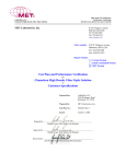
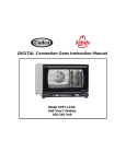
Energy Saving Device, Model: FORCE Tested under UL 916 - UL Standard for Safety Energy Management Equipment - Fourth Edition, and CAN/CSA C22.2 No. 205-M1983 (R 2009) Signal Equipment - First Edition File: E113167 MET Report: 31385 Approved: October 4, 2011 Applicant: Enposs Inc. Beuksan Disital Vally 5-Cha 101-Ho, Gasan-Dong Kumchun-gu Seoul, Korea Prepared By: MET Laboratories, Inc. 914 West Patapsco Avenue Baltimore, Maryland 21230-3432 (410) 949-1802 © Copyright 2013 This report shall not be reproduced except in full, without the express written consent of MET Laboratories, Inc. NRTL Listing MET Recognition MET Classification Mexican Certification MET-C Listing MET-C Recognition MET-C Classification Page 1 File: E113167 MET Report: 31385 Table of Contents CHANGE RECORD ................................................................................................................................................... 3 DESCRIPTION ........................................................................................................................................................... 4 GENERAL REQUIREMENTS .................................................................................................................................. 5 MARKINGS ................................................................................................................................................................. 7 APPLICANT’S RESPONSIBILITIES ...................................................................................................................... 8 PRODUCT MODIFICATION ........................................................................................................................................... 8 MANUFACTURING AND PRODUCTION-LINE TESTS AND DOCUMENTATION PERFORMED BY MANUFACTURER. ........... 9 CRITICAL COMPONENTS .................................................................................................................................... 10 FIGURES ................................................................................................................................................................... 11 TESTING CONSIDERATIONS .............................................................................................................................. 13 CONCLUSION .......................................................................................................................................................... 14 Page 2 File: E113167 MET Report: 31385 Change Record Change Number - Description Approval Date Project Number Page 3 File: E113167 MET Report: 31385 Description Product(s) Covered: • Energy Saving Device, model: FORCE Electrical Rating: • 100V-600V, 60 Hz, 50KVA Engineering Considerations (Not For Field Representative's Use): • The Energy Saving Device, model: FORCE has been investigated in accordance with UL 916 - UL Standard for Safety Energy Management Equipment - Fourth Edition, and CAN/CSA C22.2 No. 205-M1983 (R 2009) Signal Equipment - First Edition. Operation/Service Instructions: • • Operations instructions are provided with the equipment.. There are no servicing instructions since the equipment is non-serviceable. The instruction manual shall include information stating that the product shall be installed in accordance with the National Electrical Code and any other applicable local electrical codes. Page 4 File: E113167 MET Report: 31385 General Requirements Scope: The requirements contained within this section apply to all products contained within this Follow-Up Service Report File. Exceptions, if any, shall be noted within the body of the report. Definitions: (as defined or used in the context of the standard) Term Definitions Listed/Recognized Component: A component evaluated to the applicable U.S. standards by a Nationally Recognized Testing Laboratory (NRTL). Certified Component: .A component evaluated to the applicable Canadian standards by a Certification Organization (CO). Listee: Applicant Measurements: All dimensions indicated in the body of this report are approximations unless otherwise indicated. Corrosion Protection: All corrosive metals shall be provided with a means to protect from corrosion. Acceptable methods include painting, plating and galvanizing. Dissimilar metals shall not be employed where reliable continuity is required. Soldered Connections: All soldered connections shall be made mechanically secure before soldering. Tack soldering is not acceptable. Acceptable forms of mechanical securement include: A) Lead is inserted through an eyelet or opening of a terminal block prior to soldering. B) Lead is inserted into a U or V shaped slot in the terminal prior to soldering. C) Lead is wrapped around a terminal post prior to soldering. D) Lead is tied to adjacent lead with wire tie-wrap near termination point. Electrical Connections: All electrical connections other than soldering shall be provided with positive detent, crimp type insulated Recognized Component connectors suitable for the voltage and temperatures involved. They shall be sized for the wire and mounting terminations. Where hazardous voltage or energy is involved, all wire connections to connectors shall employ a recognized method of double securement. Where fork-type lugs are used, they shall be snap-on or up-turned lug type. Mechanical Assembly: All parts shall be secured by welding, bolts/nuts with lock or star washers, or thread forming screws. Operation/Service Manual: Unless otherwise noted, each unit shall be provided with an operations and installations manual. Page 5 File: E113167 MET Report: 31385 General Requirements (Continued) Creepage and Clearances: Between Line voltage parts and Enclosure Voltages up to (Vrms) Insulation Required Creepage (Over Surface) Clearance (Through Air) 600 Basic 0.5 inch 0.5 inch Internal Plastics: Shall be a Recognized/Certified Component, Plastic, rated minimum 94V-2. Wire Connectors: (Various crimp-type) Shall be Listed/Recognized/Certified Components sized for the wire and mounting terminations. Both the wire insulation and the conductor shall be crimped. Fuseholder: Operator accessible fuseholders, when provided, are connected to the ungrounded conductor(s) of the primary circuit. Internal Wiring: All internal wiring and connections are properly jacketed or enclosed within the equipment. Wiring is routed and secured to reduce the possibility of stress being transmitted to electrical connections, as necessary. All internal conductors in the secondary circuits are routed away from primary circuit conductors and from uninsulated live parts. There is no internal wiring subject to contact by the user when the product is employed as intended. The internal wiring is acceptable for conditions of service to which it will be subjected. Internal conductors consist of Recognized Component AWM insulated individual conductors; sized in accordance with the National Electric code and Canadian Electrical code, as may be applicable for the current expected in the conductor, rated VW-1, 300V, 90°C, and signal level ribbon wiring of flammability rating VW-1. Interconnecting Cords and Cables: Flexible telecommunication cord and cable assemblies employed for interconnection between components are to be rated for and comply with temperatures, exposure to oil or grease and other conditions of service within the environment the product is to be utilized. Page 6 File: E113167 MET Report: 31385 Markings Etching, molding, die-stamping, silk-screening, stamped-, or etched-metal labels secured by rivets or screws are considered permanent. Recognized/Certified Component, Marking and Labeling Systems, suitable for the surface to which it is applied is also considered permanent. It may be necessary, in certain provinces of Canada, to provide warning/cautionary markings in both English and French languages. Each product is to be permanently marked with the following information: a. The MET Mark (refer to MET Applicant Contract), with the applicant/listee name or alternate listee name as identified within this report, trade name or trade mark, product model number, and a date of manufacture or serial number. The date or other dating period of manufacture shall not exceed any three consecutive months.. b. Method of applying the MET Mark: Direct Imprinting Purchasing Labels from MET Laboratories, Inc. Approved MET Mark: c. A rating label adjacent to the inlet connector identifying the voltage, current or power, and frequency rating for the equipment. Page 7 File: E113167 MET Report: 31385 Applicant’s Responsibilities Product Modification Minor product modifications by the manufacturer may be allowed using the following guidelines: 1. Components identified in this report as "Listed, Recognized, or Certified" and NOT identified with a manufacturer name or part number may be exchanged with an alternate "Listed, Recognized, or Certified" component of equivalent value. Example: Appliance Inlet Connector - Listed/Certified Component, IEC 320 style male connector, rated 250 volts and 20 amperes. Mechanically secured to the front panel with screws and locking washers. This inlet connector may be replaced with any Listed/Certified inlet connector with the same ratings as stated and where mechanical securement is maintained. 2. Components identified by a manufacturer name, part number, or with specific comments, (such as AC only, indoor use only, approved for use in this product only), may NOT be replaced or modified without prior approval from MET Laboratories. Example: Circuit Breaker - Recognized/Certified Component, ABCD Co. P/N XYZ123, rated 250 volts maximum, 50/60 Hz, 25 full-load amperes, 31.3 trip amperes. Toggle handle marked with IEC on/off symbols. Mechanically secured to the front panel with screws and locking washers. This circuit breaker can NOT be modified or changed without prior approval by MET Laboratories, Inc. For your convenience a Project Amendment Request (PAR) form is available for download at http://www.metlabs.com/Portals/0/PDF/Par.pdf. For any changes related to product construction, manufacturing locations, if the product is intended to be marketed/sold under an alternate name or model number than that originally listed, or any issues which would require notification or change in the status of this file, please complete the form and return to MET Laboratories, Inc. following the instructions provided on the form. If you are terminating or temporarily suspending production of this product for an extended period, please send a letter on company letterhead to: MET Laboratories, Inc. Attn: Follow Up Services Department 914 West Patapsco Avenue Baltimore, Maryland 21230 USA Fax: (410) 354-3313 Page 8 File: E113167 MET Report: 31385 Applicant’s Responsibilities (Continued) Manufacturing and Production-Line Tests and Documentation performed by Manufacturer. This product is exempt from production line testing. Page 9 File: E113167 MET Report: 31385 Critical Components Manufacturer /Trademark Type/ Model Object/ Parts No. 1/1 Enclosure (Top case, Bottom case) SABIC - Description Overall dimensions shall be 60mm (W) by 47mm (H) by 55mm (D) Valox® V3900WX Technical Data Standard (Edition / year) Figure /item No. PBT/PC blend, flame rated 945VA, 40 ºC UL 94, UL 746C Mark(s) of Conformity UL/CSA Recognized Secured Method Secured together with four screws The enclosure has an opening which is factory fitted with a R/C wiring hub which has the supply conductor integrated into the hub. On the rear side of the enclosure are provided four holes of 3mm diameter which are provided for wall mounting. 1/2 Supply conductor various various 2/1 Bushing / Strain relief Jacob, GmbH Series PG7 2/2 Crimp pin Jeon-O Electric Co., Ltd. Series JOF, JS, JSL, or JSS Potting material EMF AYAA0936123.001 2/3 Not shown UL AWM wiring type 1015, size 10AWG, 600V, 105 ºC. CSA type TEW, same electrical ratings Designed installation hole size: 0.5 inch, conductor size range: AWG #14 to #10 End of wire crimp pin designed for a wire size range of AWG #14 to #10 Mica based mineral material, Flame rated 94V0 UL 758 UL/CSA Recognized UL 514B UL/CSA Recognized UL 486A UL 486B UL/CSA Recognized UL 94 UL Recognized Secured into wiring bushing/strain relief described below using a locking wire nut. Secured into a 0.5” enclosure hole using an integral bushing locking nut. Secured into the wiring bushing/strain relief using a locking wire nut. Material selfmolds into the enclosure and is retained in place by the enclosure walls Page 10 File: E113167 MET Report: 31385 Figures Figure 1 Page 11 File: E113167 MET Report: 31385 Figures (Continued) Figure 2 Page 12 File: E113167 MET Report: 31385 Testing Considerations A sample of the Energy Saving Device, model: FORCE was subjected to the following test program with satisfactory results. All tests were conducted in accordance with UL 916 - UL Standard for Safety Energy Management Equipment - Fourth Edition, and CAN/CSA C22.2 No. 205-M1983 (R 2009) Signal Equipment - First Edition. Only these tests were considered necessary due to engineering considerations. Detailed test results are on file at MET Laboratories under project number 31385. TESTS CONDUCTED: 1. Power Input Test 2. Temperature Test 3. Leakage Current Test 4. Dielectric Voltage Withstand Test 5. Strain Relief Test 6. Mounting Test 7. Mold Stress Relief Test 8. Resistance to Impact Tests 9. Resistance to Crushing Test 10. Cover Retention Test 11. Moisture Absorption Test 12. Enclosure Material Dielectric Strength Test Page 13 File: E113167 MET Report: 31385 Conclusion The product covered by this report have been tested, examined, and found to comply with the applicable requirements of UL 916 - UL Standard for Safety Energy Management Equipment - Fourth Edition, and CAN/CSA C22.2 No. 205-M1983 (R 2009) Signal Equipment - First Edition. This certification has been granted under a System 3 program as defined in ISO Guide 67. Prepared By: Harold Raab Senior Project Engineer, Safety Laboratory Approved By: Rick Cooper Director of Laboratory Operations, Safety Laboratory Last Page Page 14