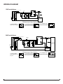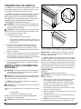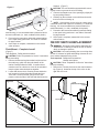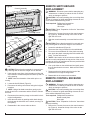
1
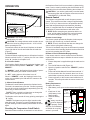
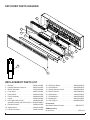
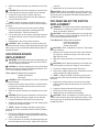
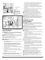
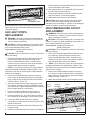
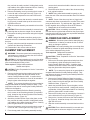
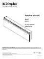
Service Manual
Model
BLF74
UL Part Number
6908740100
IMPORTANT SAFETY INFORMATION: Always read this manual first before attempting to service this fireplace. For your
safety, always comply with all warnings and safety instructions contained in this manual to prevent personal injury or property damage.
Dimplex North America Limited
1367 Industrial Road Cambridge ON Canada N1R 7G8
1-888-346-7539 www.dimplex.com
In keeping with our policy of continuous product development, we reserve the right to make changes without notice.
© 2013 Dimplex North America Limited
REV
PCN
DATE
00
-
26-NOV-13
7400740000R00
TABLE OF CONTENTS
Operation. . . . . . . . . . . . . . . . . . . . . . . . . . . . . . . . . . . . . . . . . . . . . . . . . . . 3
Maintenance. . . . . . . . . . . . . . . . . . . . . . . . . . . . . . . . . . . . . . . . . . . . . . . . . 4
Exploded parts diagram. . . . . . . . . . . . . . . . . . . . . . . . . . . . . . . . . . . . . . . 5
Replacement Parts List. . . . . . . . . . . . . . . . . . . . . . . . . . . . . . . . . . . . . . . . 5
Wiring Diagram . . . . . . . . . . . . . . . . . . . . . . . . . . . . . . . . . . . . . . . . . . . . . . 6
Preparation for service. . . . . . . . . . . . . . . . . . . . . . . . . . . . . . . . . . . . . . . . 7
Instructions for removing from wall . . . . . . . . . . . . . . . . . . . . . . . . . . . . . 7
Surface Mount. . . . . . . . . . . . . . . . . . . . . . . . . . . . . . . . . . . . . . . . . . . . . . . . . . . . . . . . . . . . . . . 7
Flush Mount – Complete In-wall . . . . . . . . . . . . . . . . . . . . . . . . . . . . . . . . . . . . . . . . . . . . . . . . 8
On/Off Switch Replacement. . . . . . . . . . . . . . . . . . . . . . . . . . . . . . . . . . . . 8
Remote Switchboard Replacement. . . . . . . . . . . . . . . . . . . . . . . . . . . . . . 9
Remote Control Receiver Replacement . . . . . . . . . . . . . . . . . . . . . . . . . . 9
LED Driver Board Replacement. . . . . . . . . . . . . . . . . . . . . . . . . . . . . . . . 10
Voltage Selector Switch Replacement. . . . . . . . . . . . . . . . . . . . . . . . . . . 10
Flicker Motor/ Flicker Rod Replacement. . . . . . . . . . . . . . . . . . . . . . . . . 11
Terminal Block Replacement. . . . . . . . . . . . . . . . . . . . . . . . . . . . . . . . . . 11
LED Light Strips Replacement. . . . . . . . . . . . . . . . . . . . . . . . . . . . . . . . . 12
High Temperature Cutout Replacement . . . . . . . . . . . . . . . . . . . . . . . . . 12
Element Replacement. . . . . . . . . . . . . . . . . . . . . . . . . . . . . . . . . . . . . . . . 13
Blower/fan Replacement. . . . . . . . . . . . . . . . . . . . . . . . . . . . . . . . . . . . . . 13
Troubleshooting Guide. . . . . . . . . . . . . . . . . . . . . . . . . . . . . . . . . . . . . . . 15
Always use a qualified technician or service agency to repair this fireplace.
! NOTE: Procedures and techniques that are considered important enough to emphasize.
CAUTION: Procedures and techniques which, if not carefully followed, will result in damage to the equipment.
WARNING: Procedures and techniques which, if not carefully followed, will expose the user to the risk of fire, serious
injury, or death.
2www.dimplex.com
OPERATION
the fireplace off and it will not come back on without being
reset. It can be reset by switching the On/Off Switch to Off
and waiting five minutes before switching the unit back on.
Figure 1
CAUTION: If you need to continuously reset the heater,
disconnect power and call Dimplex customer service at
1-888-DIMPLEX (1-888-346-7539).
Remote Control
C
B
A
WARNING: This electric firebox must be properly in-
stalled before it is used.
CAUTION: The voltage selector switch needs to be set
to reflect the incoming voltage to the unit - 115V or 230V
before operating the unit.
The manual controls for the electric fireplace are located
on the right side of the unit and inside the air intake slot
(Figure 1).
A. On/Off Switch
The On/Off Switch supplies power to all fireplace functions.
When the switch is in the “ I ” position, the unit is on. When
in the “ O ” position, the fireplace is off.
B. 3-Position Switch
The 3-position Switch changes the mode the fireplace operates in and has three positions: “ MANUAL ”; “ OFF ”; and “
REMOTE ”.
In “ MANUAL ” mode, the fireplace’s three levels of operation are controlled by the manual control buttons.
In “ OFF ” mode, power to all functions is cut off.
When in “ REMOTE ” mode, the fireplace’s levels of operation are controlled by the ON and OFF buttons on the
remote control.
C. Manual Control Buttons
The Manual Control Buttons operate the fireplace levels.
The level is increased every time the “I” button is pressed
the unit will cycle the levels through sequentially (from off):
flames only; to flames and heat.
! NOTE: There is a third level that does not change the
output, before cycling back to flame only.
The fireplace can be turned off at any point by pressing the
“ O ” button.
! NOTE: The heater may emit a slight, harmless odor
when first used. This odor is a normal condition caused
by initial heating of internal heater parts and will not occur
again.
Resetting the Temperature Cutoff Switch
Should the heater overheat, an automatic cut out will turn
The fireplace is supplied with a radio frequency remote
control. This remote control has a range of approximately
50 ft. (15.25 m), it does not have to be pointed at the fireplace and can pass through most obstacles (including
walls). It is supplied with one of hundreds of independent
frequencies to prevent interference with other units.
! NOTE: Before attempting any operation with the remote, pull the plastic insulator strip out from between
the remote casing and battery cover (Figure 2).
Remote Control Usage
The remote control operates the fireplace levels sequentially (from off): flames only; to flames and heat.
! NOTE: There is a third level that does not change the
output, before cycling back to flame only.
The level is increased every time the ON button is pressed
on the remote control and the fireplace can be turned off at
any point by pressing the OFF button.
Remote Control Initialization/Reprogramming
If the remote control or remote control receiver has been
replaced, follow these steps to initialize the remote control
and receiver:
1. Ensure that power is supplied through the main service
panel.
2. Turn On/Off Switch to ON (Figure 1A).
3. Move the 3-position switch to the “ REMOTE ” position
(Figure 1B).
4. Press and hold the Manual Control Button marked “ I ”
for five seconds. After five seconds, there is a 10 second window to press any button on the remote control.
5. Press any button on the remote control within that 10
seconds. This will synchronize the remote control and
receiver.
Battery Replacement
To replace the battery:
1. Slide battery cover open on the remote control (Figure
2).
Figure 2
2. Install one 12-Volt
On
(A23) battery in the
Button
battery holder.
Off Button
3. Close the battery
cover.
Battery must be re- Plastic
cycled or disposed Strip
of properly. Check
with your Local Authority
Battery
or Retailer for recycling
Cover
advice in your area.
3
MAINTENANCE
WARNING: Disconnect power
and allow heater to cool
before attempting any maintenance or cleaning to reduce
the risk of fire, electric shock or damage to persons.
! NOTE: The fireplace should not be operated with an
accumulation of dust or dirt on or in the unit, as this can
cause a build up of heat and eventual damage. For this
reason the heater must be inspected regularly, depending
upon conditions and at least at yearly intervals.
Partially Reflective Glass Cleaning
The partially reflective glass is cleaned in the factory during the assembly operation. During shipment, installation,
handling, etc., the partially reflective glass may collect dust
particles; these can be removed by dusting lightly with a
clean dry cloth.
To remove fingerprints or other marks, the partially reflective glass can be cleaned with a damp cloth. The partially
reflective glass should be completely dried with a lint free
cloth to prevent water spots. To prevent scratching, do not
use abrasive cleaners.
Fireplace Surface Cleaning
Use only a damp cloth to clean painted surfaces of the
fireplace. Do not use abrasive cleaners.
Servicing
Except for installation and cleaning described in this manual, an authorized service representative should perform any
other servicing.
4www.dimplex.com
EXPLODED PARTS DIAGRAM
3
1
2
6
9
12
7
10
14
11
8
13
5
15
4
REPLACEMENT PARTS LIST
1.
2.
3.
4.
5.
6.
7.
8.
Element. . . . . . . . . . . . . . . . . . . . . . . . . 2200510700RP
Partially Reflective Glass Kit. . . . . . . . . 9600750100RP
Blower Assembly. . . . . . . . . . . . . . . . . . 5300160300RP
Front Glass. . . . . . . . . . . . . . . . . . . . . . 6908730100RP
Flicker Motor. . . . . . . . . . . . . . . . . . . . . 2000220100RP
Flicker Assembly . . . . . . . . . . . . . . . . . 5902490100RP
Cutout. . . . . . . . . . . . . . . . . . . . . . . . . . 2300201600RP
LED Light Panel (3/unit). . . . . . . . . . . . 3000830200RP
(Serial #’s starting with 28113-28313 . 3000830100RP)
9. Remote Receiver . . . . . . . . . . . . . . . . . 3000821000RP
10. Switch Board. . . . . . . . . . . . . . . . . . . . . 3000821100RP
11. LED Driver Board. . . . . . . . . . . . . . . . . 3000810100RP
12. LED Driver Board. . . . . . . . . . . . . . . . .
13. On/Off Switch . . . . . . . . . . . . . . . . . . . .
14. Voltage Selector Switch . . . . . . . . . . . .
15. Remote Control. . . . . . . . . . . . . . . . . . .
16. Glass Media . . . . . . . . . . . . . . . . . . . . .
17. Terminal Block. . . . . . . . . . . . . . . . . . . .
18. Mounting Kit . . . . . . . . . . . . . . . . . . . . .
19. 120V Plug Kit . . . . . . . . . . . . . . . . . . . .
3000810200RP
2800070400RP
2800080100RP
3000370900RP
1400070100RP
4000070100RP
9600760100RP
9600850100RP
Accessories
Wall Switch Remote Control . . . . . . . . . . . . . . WRCPF-KIT
OEM Accessory
River Rocks. . . . . . . . . . . . . . . . . . . . . . . . . . . . . . DFS1314
5
WIRING DIAGRAM
120V Installations
VOLTAGE SELECTOR SWITCH
CONTROL PCB
L1
L
THERMAL
CUTOUT
L1
RL3
RL2
RL1
LED CONTROL BOARD
LED LIGHTS
LED CONTROL BOARD
LED LIGHTS
FLAME MOTOR
CAPACITOR
3
HEATING ELEMENT
120
HEATING ELEMENT
240
4
N
N
N
See Options
Below
COMM
BLOWER MOTOR
2
6
1
5
Different Heat Control Options
1. Regular installation
attach N and L2 together
2. For No Heat installations
leave L2 unconnected with
a wire connector on the end
N
3. For installation with a
Heat Disconnect Switch
N
N
L2
L2
L2
Wall On/Off Switch
240V Installations
VOLTAGE SELECTOR SWITCH
L1
L1
L
RL3
RL2
RL1
LED CONTROL BOARD
LED LIGHTS
LED CONTROL BOARD
FLAME MOTOR
LED LIGHTS
3
CAPACITOR
HEATING ELEMENT
120
HEATING ELEMENT
240
4
CONTROL PCB
THERMAL
CUTOUT
N
N
N
240 V~ / 60 HZ
Power Supply
(Breaker Panel)
N
COMM
BLOWER MOTOR
2
6
1
5
L2
See Options
Below
L2
Different Heat Control Options
1. Regular installation
attach Neutral and L2 to
the panel
L2
2. For No Heat installations
leave L2 unconnected with
a wire connector on the end
3. For installation with a
Heat Disconnect Switch
L2
L2
Wall On/Off
Switch
6www.dimplex.com
PREPARATION FOR SERVICE
Figure 3
Mounts (4)
!
NOTE: All components are replaceable from the front
of the fireplace while the unit is mounted on the wall, with
the exception of replacement of the power cord.
! NOTE: If the power cord needs replacing or if the unit
needs to be removed from the wall for any other reason
please begin service by following the “PREPARATION
FOR SERVICE” instructions, then move on to the section
“INSTRUCTIONS FOR REMOVING FROM WALL”.
Tools Required: Philips head screwdriver
W
ARNING: Disconnect power before attempting any
maintenance or cleaning to reduce the risk of electric
shock or damage to persons.
CAUTION: If unit was operating prior to servicing allow
at least 10 minutes for lights and heating elements to cool
off to avoid accidental burning of skin.
1. Disconnect power source.
• Unplug the fireplace from the outlet.
• If unit has been hardwired for power or outlet is not
accessible from the front, turn the breaker off at the
electrical panel.
2. Remove the front glass assembly by removing the
4 screws (1 on the left and 1 on the right side and 1
on either side of the top front vent opening). These
screws secure the front glass panel to the inside of the
fireplace. (Figure 4)
3. Lift the front glass assembly off of the 4 mounts located
between the outer and inner casing of the fireplace: 2
on the left and 2 on the right. (Figure 3) Carefully place
the glass assembly aside in a safe location.
4. Proceed to the instructions within this manual relating
to the repair being performed - see Table of Contents
for page number.
INSTRUCTIONS FOR REMOVING
FROM WALL
W
ARNING: Disconnect power before attempting any
maintenance or cleaning to reduce the risk of electric
shock or damage to persons.
CAUTION: If unit was operating prior to servicing allow
at least 10 minutes for lights and heating elements to cool
off to avoid accidental burning of skin.
! NOTE: Only required for replacement of the power
cord or removal from service.
CAUTION: Follow “Preparation for Service” instructions
before proceeding.
Mounting - The fireplace may be mounted in one of 2 methods:
• Surface Mount
• Flush Mount (completely in the wall)
Identify the type of mounting and follow the appropriate
instructions in the following pages.
CAUTION: Two people will be required for removal
Hooks (4)
Figure 4
Tab
and re-installation of the fireplace. The unit is approx. 74
5/16”w x 19 1/2”h x 7”d. Weight is approximately 130 lbs.
CAUTION: To prevent injury or damage, turn off the
breaker in your electrical panel prior to attempting to remove this unit off the wall.
! NOTE: If fireplace is hard wired directly to the electrical panel, and there is not enough slack in the wires within
the wall to reach your work area, remove the electrical junction box cover located on the bottom right by removing the
1 screw on the front of the cover. Lift the cover off and set
aside. Disconnect the 3 wire connectors connected to the
power source, taking note of their original configuration.
Surface Mount
(Figure 6)
Tools Required: Philips head screwdriver
CAUTION: Follow “Preparation for Service” instructions
before proceeding.
1. Remove the decorative glass ember-bed pieces from
the media tray, which lies along the bottom of the
interior Partially Reflective Glass. A medium sized
container such as a bucket or a box will be needed to
keep the glass ember-bed pieces together.
2. On the bottom of the unit remove the securing screw
from the L-bracket. (Figure 5)
3. With one person on either end of the unit lift the unit up
and off of the wall.
4. Carefully lay the unit down on a solid flat surface with
the front of the unit facing up.
! NOTE: If the surface you are using as a work area on
is a finished surface that is prone to scratches (i.e. hard7
Figure 5
wood flooring), it is recommended that a protective barrier
be used underneath, (i.e. cloth, cardboard, thick plastic).
5. Proceed to the instructions within this manual relating
to the repair being performed - see Table of Contents
for page number.
6. Once repair is complete, reassemble in the reverse
order as above.
Flush Mount – Complete In-wall
(Figure 7)
Tools Required: Philips head screwdriver
CAUTION: Follow “Preparation for Service” instructions
before proceeding.
1. Remove the decorative glass ember-bed pieces from
the media tray, which lies along the bottom of the
interior Partially Reflective Glass. A medium sized
container such as a bucket or a box will be needed to
keep the glass ember-bed pieces together.
2. Locate and remove the 4 mounting screws inside the
unit located on left and right side towards the front.
There are 2 screws per side, going from the side
panels out into the side of the wall stud that frames the
fireplace. (Figure 7)
CAUTION: The unit should be supported while removing the screws to prevent the unit from falling.
3. Remove the fireplace out of the opening by slightly lifting and pulling forward.
4. Carefully lay the unit down on a solid flat surface with
the front of the unit facing up.
! NOTE: If the surface you are using as a work area is
a finished surface that is prone to scratches (i.e. hardwood
flooring), it is recommended that a protective barrier be
used underneath, (i.e. cloth, cardboard, thick plastic).
5. Proceed to the instructions within this manual relating
to the repair being performed - see Table of Contents
for page number.
6. Once repair is complete, reassemble in the reverse
order as above.
ON/OFF SWITCH REPLACEMENT
W
ARNING: Disconnect power before attempting any
maintenance or cleaning to reduce the risk of electric
shock or damage to persons.
CAUTION: If unit was operating prior to servicing allow
at least 10 minutes for lights and heating elements to cool
off to avoid accidental burning of skin.
Tools required: Phillips head screwdriver.
Needle nosed pliers.
CAUTION: Follow “Preparation for Service” instructions
before proceeding.
1. Remove the 2 screws, that secure the controls assembly (Figure 8), located at the top of the mirror on the
right side of the unit.
Figure 7
Figure 6
Wall Surface
Mounting Hole
8www.dimplex.com
REMOTE SWITCHBOARD
REPLACEMENT
Figure 8
Controls Assembly
Retaining Screws
Figure 9
6 LED
Driver Board
12 LED
Driver Board
Remote
Receiver
On/Off
Switch
Switch
Board
Voltage
Selector
Switch
2. Slide the controls assembly out toward the front of the
unit.
CAUTION: Ensure that the assembly is removed carefully, ensuring that no wires are caught or over strained.
3. Using needle nose pliers, pinch the tabs on either side
of the switch to release and push the switch up and out
of the opening.
! NOTE: Note the orientation of the switch prior to removing.
4. Locate the On/Off Switch (Figure 9).
5. Disconnect the wiring connections noting their original
locations.
! NOTE: Using a flat head screwdriver gently pry between the end of the connectors and the switch to release
the wires.
6. Reconnect wires onto the prongs on the switch in their
original configuration.
7. Insert the new switch by pushing switch back through
the hole past the side tabs on the switch, securing it in
the opening.
8. Reassemble in the reverse order as above.
W
ARNING: Disconnect power before attempting any
maintenance or cleaning to reduce the risk of electric
shock or damage to persons.
CAUTION: If unit was operating prior to servicing allow
at least 10 minutes for lights and heating elements to cool
off to avoid accidental burning of skin.
Tools required: Phillips head screwdriver.
Needle nosed pliers
Wire snips
CAUTION: Follow “Preparation for Service” instructions
before proceeding.
1. Remove the 2 screws, that secure the controls assembly (Figure 8), located at the top of the mirror on the
right side of the unit.
2. Slide the controls assembly out toward the front of the
unit.
CAUTION: Ensure that the assembly is removed carefully, ensuring that no wires are caught or over strained.
3. Locate the switchboard (Figure 9).
4. Disconnect the wiring harness from the switchboard.
5. To remove the switchboard off of the plastic mounting
tabs, pinch the plastic mounting tabs with needle nose
pliers. Pull the old board off.
! NOTE: If the location of the unit does not allow for the
tabs to be easily manipulated, the top portion of the mounting tabs can be cut off (replacement ones are provided with
the replacement switchboard).
6. Line up the holes on the switchboard and gently press
the new board onto the mounts. Make sure the board
is secure.
7. Reconnect the wire harness onto the back of the
switchboard in its original configuration. .
8. Reassemble in the reverse order as above.
REMOTE CONTROL RECEIVER
REPLACEMENT
W
ARNING: Disconnect power before attempting any
maintenance or cleaning to reduce the risk of electric
shock or damage to persons.
CAUTION: If unit was operating prior to servicing allow
at least 10 minutes for lights and heating elements to cool
off to avoid accidental burning of skin.
Tools required: Phillips head screwdriver.
Needle nosed pliers.
Wire snips
CAUTION: Follow “Preparation for Service” instructions
before proceeding.
1. Remove the 2 screws, that secure the controls assembly (Figure 8), located at the top of the mirror on the
right side of the unit.
9
2. Slide the controls assembly out toward the front of the
unit.
CAUTION: Ensure that the assembly is removed carefully, ensuring that no wires are caught or over strained.
3. Locate the remote control receiver (Figure 9).
4. Transfer the wiring connections from the existing receiver to the new receiver.
! NOTE: Using a flat head screwdriver gently pry between the end of the connectors and the board to release
the wires.
5. Remove the remote control receiver off the plastic
mounts by pinching the plastic mounting tabs with
needle nose pliers. Pull the old board off.
6. Line up the holes on the receiver and gently press the
new board onto the mounts. Make sure the board is
secure.
7. Reassemble in the reverse order as above.
CAUTION: When re-installing, be sure the wires are
guided and tucked into the proper openings along the right
side so they are not pinched and allows enough space to
reinstall the panel.
LED DRIVER BOARD
REPLACEMENT
W
ARNING: Disconnect power before attempting any
maintenance or cleaning to reduce the risk of electric
shock or damage to persons.
CAUTION: If unit was operating prior to servicing allow
at least 10 minutes for lights and heating elements to cool
off to avoid accidental burning of skin.
Tools required: Phillips head screwdriver
Needle nosed pliers
Wire snips
CAUTION: Follow “Preparation for Service” instructions
before proceeding.
1. Remove the 2 screws, that secure the controls assembly (Figure 8), located at the top of the mirror on the
right side of the unit.
2. Slide the controls assembly out toward the front of the
unit.
CAUTION: Ensure that the assembly is removed carefully, ensuring that no wires are caught or over strained.
3. Locate the defective LED driver board (Figure 9).
4. Transfer the wiring connections from the existing driver
board to the new driver board.
! NOTE: Using a flat head screwdriver gently pry between the end of the connectors and the board to release
the wires.
5. Remove the LED driver board off the plastic mounts
by pinching the plastic mounting tabs with needle nose
pliers. Pull the old board off.
6. Line up the holes on the driver board and gently press
the new board onto the mounts. Make sure the board
is secure.
7. Reassemble in the reverse order as above.
CAUTION: When re-installing, be sure the wires are
guided and tucked into the proper openings along the right
side so they are not pinched and allows enough space to
reinstall the panel.
VOLTAGE SELECTOR SWITCH
REPLACEMENT
W
ARNING: Disconnect power before attempting any
maintenance or cleaning to reduce the risk of electric
shock or damage to persons.
CAUTION: If unit was operating prior to servicing allow
at least 10 minutes for lights and heating elements to cool
off to avoid accidental burning of skin.
Tools Required: Philips head screwdriver
Flat head screwdriver
Wire cutters/strippers
Needle nose pliers
CAUTION: Follow “Preparation for Service” instructions
before proceeding.
1. Remove the 2 screws, that secure the controls assembly (Figure 8), located at the top of the mirror on the
right side of the unit.
2. Slide the controls assembly out toward the front of the
unit.
CAUTION: Ensure that the assembly is removed carefully, ensuring that no wires are caught or over strained.
3. Locate the voltage selector switch (Figure 9).
4. Remove the voltage selector wire connections from the
switch noting their original locations.
! NOTE: Using a flat head screwdriver gently pry between the end of the connector and the switch to release
the wires.
5. Depress the retainer clips on the rear of the voltage
selector switch and push the switch out of the front of
the panel.
6. Properly orient and reinstall the new switch.
7. Reconnect all of the wiring connections.
8. Reassemble in the reverse order as above.
CAUTION: When re-installing, be sure the wires are
guided and tucked into the proper openings along the right
side so they are not pinched and allows enough space to
reinstall the panel.
10www.dimplex.com
Figure 10
Access Covers
Figure 11
by loosening the 3 small Philips screws holding each
wire in place then gently pulling the wires out of the
terminal block - noting their original locations.
7. Remove the 2 screws holding the flicker motor to the
mounting bracket. Gently pull the motor away from the
flicker rod.
8. Properly orient the new flicker motor onto the bracket
and re-attach with the 2 mounting screws.
9. Reassemble in the reverse order as above.
CAUTION: When removing and replacing the flicker
motor try to keep any slight bending of the flicker rod
minimal so as to not damage it. If flicker rod is damaged, it
should be replaced to ensure proper operation.
CAUTION: When re-installing, be sure the wires are
guided and tucked into the proper openings along the right
side so they are not pinched and allows enough space to
reinstall the panels.
TERMINAL BLOCK
REPLACEMENT
Retaining
Screws
Flicker
Assembly
Flicker
Motor
Terminal
Block
FLICKER MOTOR/ FLICKER ROD
REPLACEMENT
W
ARNING: Disconnect power before attempting any
maintenance or cleaning to reduce the risk of electric
shock or damage to persons.
CAUTION: If unit was operating prior to servicing allow
at least 10 minutes for lights and heating elements to cool
off to avoid accidental burning of skin.
Tools required: Phillips head screwdriver.
CAUTION: Follow “Preparation for Service” instructions
before proceeding.
1. In the bottom right hand of the unit, remove the access
covers. (Figure 10)
2. If the flicker rod needs to be changed it can be removed by holding the gasket and sliding it to the left.
This will disengage it from the motor. It will then be
possible to remove it out of the opening.
3. To replace the flicker motor, remove the second access
cover (Figure 10).
4. Remove the 2 retaining screws (Figure 11) on the
bracket that the flicker motor is mounted to remove the
assembly.
5. Carefully remove the entire assembly.
! NOTE: It may be easier to remove the flicker rod (see
step 2) to allow the whole assembly to be removed.
6. Remove the flicker motor wires from the terminal block
W
ARNING: Disconnect power before attempting any
maintenance or cleaning to reduce the risk of electric
shock or damage to persons.
CAUTION: If unit was operating prior to servicing allow
at least 10 minutes for lights and heating elements to cool
off to avoid accidental burning of skin.
Tools required: Phillips head screwdriver.
CAUTION: Follow “Preparation for Service” instructions
before proceeding.
1. In the bottom right hand of the unit, remove both of the
access cover. (Figure 10)
2. Remove the 2 retaining screws (Figure 11) on the
bracket that the flicker motor is mounted to remove the
assembly.
3. Carefully remove the entire assembly.
! NOTE: It may be easier to remove the flicker rod (see
step 2 of Flicker Motor Replacement) to allow the whole
assembly to be removed.
4. Remove the wires from the terminal block by loosening the small Philips screws holding each wire in place
then gently pulling the wires out of the terminal block noting their original locations.
5. Remove the 2 screws holding the terminal block to the
mounting bracket. Gently pull the terminal block away
from the bracket.
6. Properly orient the new terminal block onto the bracket
and re-attach with the 2 mounting screws.
7. Reassemble in the reverse order as above.
CAUTION: When removing and replacing the flicker
motor try to keep any slight bending of the flicker rod
minimal so as to not damage it. If flicker rod is damaged, it
should be replaced to ensure proper operation.
CAUTION: When re-installing, be sure the wires are
11
Figure 12
Retaining Brackets
guided and tucked into the proper openings along the right
side so they are not pinched and allows enough space to
reinstall the panels.
LED LIGHT STRIPS
REPLACEMENT
W
ARNING: Disconnect power before attempting any
maintenance or cleaning to reduce the risk of electric
shock or damage to persons.
CAUTION: If unit was operating prior to servicing allow
at least 10 minutes for lights and heating elements to cool
off to avoid accidental burning of skin.
Tools required: Phillips head screwdriver
Wire Snips
CAUTION: Follow “Preparation for Service” instructions
before proceeding.
1. Remove the decorative glass ember-bed pieces from
the media tray, which lies along the bottom of the
interior Partially Reflective Glass. A medium sized
container such as a bucket or a box will be needed to
keep the glass ember-bed pieces together.
! NOTE: Try to ensure the pieces do not get pushed or
wedged underneath the Partially Reflective Glass. They
may obstruct the ease of removing the Partially Reflective
Glass from the fireplace.
2. Remove the Partially Reflective Glass by removing
the 2 screws on each retaining bracket; (2 brackets in
total), located on the left and right side of the Partially
Reflective Glass. (Figure 12)
3. Attach the provided suction cups to the glass, so that
they can both be easily reached. Holding both suction
cup handles, tilt the glass forward and lift out. Carefully
place the glass aside in a safe location.
4. Remove the plastic media tray by removing the 6
screws: 3 on the left and 3 on the right of the tray.
5. Remove the flicker rod. This can be done by sliding it
to the left which will disengage it from the flicker motor.
6. Locate the LED strip that needs to be replaced.
7. Cut the wires on either side of the housing bracket that
attache to the board.
8. Remove the 2 screws that attach the LED strip to the
housing bracket.
9. Replace the LED strip with the new one, by feeding the
wires through the housing bracket openings and screwing the new board to the bracket.
10. Strip approximately 1/2” of the plastic off of the end of
the wires that were previously cut.
11. Using the provided wire connectors, attach the LED
strip wires and the cut unit wires together.
12. Reassemble in the reverse order as above.
CAUTION: When removing and replacing the flicker
motor try to keep any slight bending of the flicker rod
minimal so as to not damage it. If flicker rod is damaged, it
should be replaced to ensure proper operation.
HIGH TEMPERATURE CUTOUT
REPLACEMENT
W
ARNING: Disconnect power before attempting any
maintenance or cleaning to reduce the risk of electric
shock or damage to persons.
CAUTION: If unit was operating prior to servicing allow
at least 10 minutes for lights and heating elements to cool
off to avoid accidental burning of skin.
Tools required: Phillips head screwdriver
Needle nosed pliers
CAUTION: Follow “Preparation for Service” instructions
before proceeding.
1. Remove the decorative glass ember-bed pieces from
the media tray, which lies along the bottom of the
interior Partially Reflective Glass. A medium sized
container such as a bucket or a box will be needed to
keep the glass ember-bed pieces together.
! NOTE: Try to ensure the pieces do not get pushed or
wedged underneath the Partially Reflective Glass. They
may obstruct the ease of removing the Partially Reflective
Glass from the fireplace.
2. Remove the Partially Reflective Glass by removing
the 2 screws on each retaining bracket; (2 brackets in
total), located on the left and right side of the Partially
Reflective Glass. (Figure 12)
3. Attach the provided suction cups to the glass, so that
Figure 13
Cover
Panel
Heating
Elements
Cutout
Blower
Assembly
Heating
Cover
12www.dimplex.com
they can both be easily reached. Holding both suction
cup handles, tilt the glass forward and lift out. Carefully
place the glass aside in a safe location.
4. Remove the heating cover by removing the 4 screws: 2
on the left and 2 on the right of the tray. (Figure 13)
5. Locate the high temperature cutout and remove the
mounting screw.
6. Remove the 2 screws, that secure the controls assembly (Figure 8), located at the top of the mirror on the
right side of the unit.
7. Slide the controls assembly out toward the front of the
unit.
CAUTION: Ensure that the assembly is removed carefully, ensuring that no wires are caught or over strained.
8. Disconnect the wiring connections noting their original
locations.
! NOTE: Using a flat head screwdriver gently pry between the end of the connectors and the board to release
the wires.
9. Properly orient the new high temperature cutout and
connect all of the wiring connections.
10. Reassemble in the reverse order as above.
ELEMENT REPLACEMENT
W
ARNING: Disconnect power before attempting any
maintenance or cleaning to reduce the risk of electric
shock or damage to persons.
CAUTION: If unit was operating prior to servicing allow
at least 10 minutes for lights and heating elements to cool
off to avoid accidental burning of skin.
Tools required: Phillips head screwdriver.
Needle nosed pliers.
CAUTION: Follow “Preparation for Service” instructions
before proceeding.
1. Remove the decorative glass ember-bed pieces from
the media tray, which lies along the bottom of the
interior Partially Reflective Glass. A medium sized
container such as a bucket or a box will be needed to
keep the glass ember-bed pieces together.
! NOTE: Try to ensure the pieces do not get pushed or
wedged underneath the Partially Reflective Glass. They
may obstruct the ease of removing the Partially Reflective
Glass from the fireplace.
2. Remove the Partially Reflective Glass by removing
the 2 screws on each retaining bracket; (2 brackets in
total), located on the left and right side of the Partially
Reflective Glass. (Figure 12)
3. Attach the provided suction cups to the glass, so that
they can both be easily reached. Holding both suction
cup handles, tilt the glass forward and lift out. Carefully
place the glass aside in a safe location.
4. Remove the heating cover by removing the 4 screws: 2
on the left and 2 on the right of the tray. (Figure 13)
5. From the top panel of the heating assembly housing,
remove the 4 screws that hold the element cover to the
housing panel.
6. Disconnect wires from the ends of the elements noting
their original locations.
! NOTE: Using a flat head screwdriver gently pry between the end of the connectors and the element to release
the wires.
! NOTE: Some of the wires may have a “piggy-back”
connector that allows a second wire to connect to the same
prong as the first wire. Try and keep the “piggy-back” connection together when pulling the wires off the element.
7. Reassemble in the reverse order as above.
CAUTION: When re-installing covers and panels, be
sure the wires are guided and tucked into the proper openings along the right side so they are not pinched and allows
enough space to reinstall panel.
BLOWER/FAN REPLACEMENT
W
ARNING: Disconnect power before attempting any
maintenance or cleaning to reduce the risk of electric
shock or damage to persons.
CAUTION: If unit was operating prior to servicing allow
at least 10 minutes for lights and heating elements to cool
off to avoid accidental burning of skin.
Tools required: Phillips head screwdriver.
Needle nosed pliers.
CAUTION: Follow “Preparation for Service” instructions
before proceeding.
1. Remove the decorative glass ember-bed pieces from
the media tray, which lies along the bottom of the
interior Partially Reflective Glass. A medium sized
container such as a bucket or a box will be needed to
keep the glass ember-bed pieces together.
! NOTE: Try to ensure the pieces do not get pushed or
wedged underneath the Partially Reflective Glass. They
may obstruct the ease of removing the Partially Reflective
Glass from the fireplace.
2. Remove the Partially Reflective Glass by removing
the 2 screws on each retaining bracket; (2 brackets in
total), located on the left and right side of the Partially
Reflective Glass. (Figure 12)
3. Attach the provided suction cups to the glass, so that
they can both be easily reached. Holding both suction
cup handles, tilt the glass forward and lift out. Carefully
place the glass aside in a safe location.
4. Remove the heating cover by removing the 4 screws: 2
on the left and 2 on the right of the tray. (Figure 13)
5. Remove the 2 screws, that secure the controls assembly (Figure 8), located at the top of the mirror on the
right side of the unit.
6. Slide the controls assembly out toward the front of the
unit.
CAUTION: Ensure that the assembly is removed carefully, ensuring that no wires are caught or over strained.
13
7. Remove the 2 screws, that secure the cover panel
(Figure 13), located at the top of the mirror on the left
side of the unit.
8. Remove the two screws on either side of the heater/
blower assembly and gently lower the assembly so that
the top can be viewed.
CAUTION: When removing the blower assembly
mounting screws, support the assembly to prevent any
damage to the unit.
9. Remove the 6 screws (3 sets) that secure the blower to
the assembly (Figure 14).
10. Disconnect the wiring connections noting their original
locations.
! NOTE: Using a flat head screwdriver gently pry
between the end of the connectors and the blower/fan to
release the wires.
11. Properly orient the new blower/fan assembly and connect all of the wiring connections.
12. Reassemble in the reverse order as above.
Figure 14
Mounting Screws
14www.dimplex.com
TROUBLESHOOTING GUIDE
PROBLEM
CAUSE
SOLUTION
General
Circuit breaker trips or fuse
blows when unit is turned on
Short in unit wiring.
Trace wiring in unit.
Improper circuit current rating
Additional appliances may exceed the current rating
of the circuit breaker or fuse. Plug unit into another
outlet or install unit on a dedicated 15 amp circuit.
Unit turns on or off by itself
Remote Control has a similar frequency
to other remotes in the area.
Replace Remote Control. Initialize to Remote Control
Receiver.
Radio frequency disturbance from outside sources.
Replace Remote Control and Remote Control Receiver where necessary. Initialize Remote Control and
Receiver.
Defective Remote Control Receiver
Replace Remote Control Receiver. Initialize Remote
Control and Receiver.
Lights dim in room while the unit
is on
Unit is drawing close to circuit current
rating
Move the unit to another outlet or install unit on a dedicated 15 amp circuit
Power cord gets warm
Normal Operation
The power cord may get slightly warm to the touch
when the heater is on
Defective power cord
Replace power cord if cord gets too hot to touch.
Appearance
Fireplace does not turn on Manu- Improper operation
ally
No incoming power from the electrical
wall socket
Fireplace does not turn on using
the Remote Control
Refer to Operation Section
Check fuse/breaker panel
Loose wiring
Check wiring connections
Defective On/Off Switch
Replace On/Off Switch
Defective Remote Switchboard
Replace Remote Switchboard
Improper operation
Refer to Operation Section
Remote Control not initialized to fireplace Initialize the Remote Control
Remote Control not working
Install new battery into the Remote Control. Initialize
Remote Control where necessary
Replace Remote Control Receiver or Remote Control
where necessary. Initialize Remover Control and
Remote Control Receiver
Flame Frozen
Flame not bright or flame not
visible
Flame Shutter
Loose wiring.
Check wiring connections
Defective Flicker Motor
Replace Flicker Motor
Defective LED Driver Board
Replace LED Driver Board
Loose wiring
Check wiring connections
Defective LED Light Strip
Replace LED Light Strip
Defective LED Driver Board
Replace LED Driver Board
Defective Flicker motor
Replace Flicker motor
15
PROBLEM
CAUSE
SOLUTION
Heater
Heater is not turning off
Heater is not turning on
Heater is turning off after a
couple of minutes of operation
Heater emits an odor
Heater fan turns on but heater
lacks heat
Heating element is glowing red
Heater fan runs continuously
Improper operation
Refer to Operation Section
Defective Remote Switchboard
Replace Remote Switchboard
Defective Remote Control Receiver
Replace Remote Control Receiver
Improper operation
Refer to Operation Section
Loose wiring
Trace wiring in unit.
Defective Remote Switchboard
Replace Remote Switchboard
Defective Heating Element
Replace Heating Element
Build up of dirt/dust in Blower/Fan
Ensure that exterior intake louvers and firebox cavity
are free of dirt/dust.
Defective Blower/Fan
Replace Blower/Fan
Normal Operation
Normal operation is when the heater emits an odor
for a brief period after the heater is initially turned on.
The heater is burning off any dust accumulated during
manufacturing or operation.
Defective Heating Element
Replace Heating Element
Improper operation
Refer to Operation Section
Loose wiring
Trace wiring in unit
Defective Heating Element
Replace Heating Element
Normal Operation
Small glowing sections of the element are considered
normal.
Defective Blower/Fan
If larger glowing sections are causing the heater to trip
the thermal cutout, unplug unit, discontinue use and
replace Blower/Fan.
Loose wiring
Trace wiring in unit
Defective Remote Switchboard
Replace Remote Switchboard
Defective Blower/Fan
Replace Blower/Fan
Dirty Blower/Fan
Ensure that exterior intake louvers and firebox cavity
are free of dirt/dust.
Defective Blower/Fan
Replace Blower/Fan
Flicker rod hitting or rubbing against
internal components
Ensure rod is straight and mounted properly in the
bracket, spinning freely away from other components.
Replace if necessary.
Defective Flicker motor
Replace Flicker motor
Noise
Excessive noise with the heater
on
Grinding or excessive noise with
the heater off
16www.dimplex.com