1
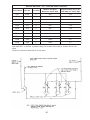
IN S TAL L AT ION , OP E R AT IN G AN D
S E R V IC E IN S T R U C T ION S F OR
" F D " F O R C E D D R AF T
S T E E L BO I L E R BU R N E R U N I T S
FOR OIL, GAS
OR COMBINATION
OIL-GAS FIRING
F o r s e r vi c e o r r e p a i r s to b o i le r, c a ll yo ur he a ti ng c o ntr a c to r. W he n s e e k i ng i nfo r m a ti o n o n b o i le r,
p r o vi d e B o i le r M o d e l Num b e r a nd S e r i a l Num b e r a s s ho wn o n Ra ti ng L a b e l.
B o i le r M o d e l Num b e r
FD ____________
B o i le r S e r i a l Num b e r
Ins ta lla ti o n D a te
6_ _ _ _ _ _ _
He a ti ng C o ntr a c to r
P ho ne Num b e r
A d d re s s
8143401R6-7/03
Price - $3.00
1
The following terms are used throughout this manual to bring attention to the presence of hazards of various risk
levels, or to important information concerning product life.
C AU T I O N
WAR N IN G
In d ic a t e s p r e s e n c e o f a h a z a r d w h ic h w ill o r
c a n c a u s e m in o r p e r s o n a l in ju r y o r p r o p e r t y
d a m a g e if ig n o r e d .
In d ic a t e s p r e s e n c e o f a h a z a r d w h ic h c a n
c a u s e s e v e r e p e r s o n a l in ju r y, d e a th o r
s u b s t a n t ia l p r o p e r t y d a m a g e if ig n o r e d .
N OT IC E
In d ic a t e s s p e c ia l in s t r u c t io n s o n
in s t a lla t io n , o p e r a t io n , o r m a in t e n a n c e
w h ic h a r e im p o r t a n t b u t n o t r e la t e d t o
p e r s o n a l in ju r y h a z a r d s .
TABLE OF CONTENTS
INTRODUCTION TO "FD" SERIES STEEL BOILER-BURNER UNITS ............................................................................... 3
DIMENSIONS AND RATING DATA ................................................................................................................................. 4 & 5
FURNACE FLOOR BLANKETS ......................................................................................................................................... 6 & 7
CERAMIC FIBER WARNING ................................................................................................................................................... 8
CLEANING INSTRUCTIONS .................................................................................................................................................... 9
BURNER DATA ............................................................................................................................................................... 10 & 11
BECKETT BURNER SPECIFICATIONS ....................................................................................................................... 12 & 13
TANKLESS HEATER PERFORMANCE ................................................................................................................................. 14
COIL RATINGS ......................................................................................................................................................................... 15
INDIRECT WATER HEATER OPERATION .......................................................................................................................... 16
COMBUSTION AND VENTILATION AIR REQUIREMENTS ............................................................................................. 16
VENTS—FAULTS AND SUGGESTIONS .............................................................................................................................. 17
EXPANSION OR AIR CUSHION TANK ................................................................................................................................ 18
PIPING—FORCED HOT WATER HEATING ........................................................................................................................ 19
PIPING—DOMESTIC HOT WATER ...................................................................................................................................... 20
PIPING—FORCED HOT WATER HEATING AND DOMESTIC HOT WATER ................................................................. 20
PIPING—DOMESTIC HOT WATER WITH STORAGE TANK ........................................................................................... 21
PIPING—RECIRCULATING DOMESTIC HOT WATER SYSTEM .................................................................................... 21
PIPING—MULTI-PURPOSE BOILER APPLICATION ......................................................................................................... 22
PIPING—MULTIPLE BOILER OPERATIONS (PARALLEL PIPING) ................................................................................ 22
ORDERING REPAIR PARTS ................................................................................................................................................... 23
JACKET PARTS IDENTIFICATION ....................................................................................................................................... 23
WARRANTY .............................................................................................................................................................. Rear Cover
2
INTRODUCTION TO "FD" SERIES
STEEL BOILER BURNER UNITS
N OT IC E
Due to an excellent combination of boiler and burner,
the "FD" Series boiler-burner units are capable of
developing the optimum in combustion and thermal
efficiencies. The burner provides 12½% CO2 for a
combustion efficiency in excess of 83% on #2 fuel oil.
Forced draft operation is accomplished by means of a
3450 RPM motor and blower wheel on the burner and a
factory sealed combustion chamber. The commonly
used refractory type combustion chamber is not
required.
A barometric damper may be required on
installations w ith a high draft condition.
FLUE DAMPER:
The boiler is provided with a breaching damper which
should be secured in the open position for initial start up
of the burner. The adjustable damper in the flue collar
at the boiler outlet is provided so that if the installer or
serviceman desires, he can easily introduce a flow
restriction at the boiler outlet and thereby increase the
pressure in the firebox. Normally, it is best to leave the
damper wide open and to control air flow to the burner
entirely by adjustments at the burner inlet. Flue
restrictions such as a partially closed damper tend to
make starts rougher. Boiler tests were run at 12½%
CO2 and 0.1 inches of water stack pressure to
demonstrate ample burner air capacity for good
performance up to this pressure. Boiler pressure drop
does not change measurably at different stack and
firebox pressures as long as the burner is adjusted to
maintain the same percent CO2.
Pressure is produced within the boiler by the "forced
draft" operation of the burner eliminating the need for a
chimney thus resulting in a substantial savings in
building costs. A vent to the outside of the building is
the only requirement. Boiler rooms can also be kept to
a minimum size since one boiler equipped with a
tankless heater can supply all of the heating
requirements for comfort heating and domestic hot
water.
For optimum performance and serviceability from these
units adhere to the following recommendations:
1) Clean boiler flueways (firetubes after removing
turbulator baffles) with a 3" OD flue brush, at least
once a year and preferably at the end of the heating
season, or as may be necessitated to remove all soot
and scale. See Page 10 for cleaning instructions.
MINIMUM INSTALLATION CLEARANCES TO
COMBUSTIBLE MATERIAL:
FRONT - 48 Inches
SIDES - 18 Inches
REAR - 18 Inches
ABOVE OR TOP - 18 Inches
VENT CONNECTOR PIPE - 18 Inches
NOTE:
2) Have burner and controls checked at least once a
year. See Pages 14, 15, 21 and 22 and burner
manual for burner adjustment specifications.
1. Listed clearances comply with American National
Standard ANSI/NFPA 31, Installation of oil burning
equipment.
3) Retain your contractor or a competent service
agency to assure that the unit is properly adjusted
and maintained.
2. FD Series boilers can be installed in rooms with
clearances from combustible material as listed
above. Listed clearances can not be reduced for
alcove or closet installations.
4) The interior of the venting must be inspected and
cleaned before the start of the heating season and
should be inspected periodically throughout the
heating season for any obstructions. A clean and
unobstructed vent is necessary to allow noxious
fumes that could cause injury or loss of life to vent
safely and will contribute toward maintaining the
boiler's efficiency.
3. For reduced clearances to combustible material,
protection must be provided as described in the
above ANSI/NFPA 31 standard.
4. Check dimensional data for boiler service
recommended clearances.
WARNING
For additional information consult the service department.
D o n o t s u p p o r t b o ile r b y p la c in g b lo c k s
a t th e fo u r (4 ) c o rn e rs o f th e b o ile r.
B o ile r b a s e m u s t b e e v e n ly s u p p o r t e d
u n d e r e n t ir e b a s e .
WAR N IN G
Upon installation of this boiler and at least once
a year thereafter the operation of the boiler
controls should be checked, particularly the low
w ater cut-off, high limit control and safety-relief
valve.
D o n o t o p e r a t e b o ile r o n c o m b u s t ib le
f lo o r w it h o u t a f a c t o r y s u p p lie d f lo o r
s h i e l d . C o n c r e t e o v e r w o o d jo i s t s i s
c o n s id e r e d c o m b u s t ib le f lo o r in g . D o n o t
o p e r a t e o n m a s o n r y f lo o r s , w h ic h m a y
c o n t a in m o is t u r e .
3
4
5
FURNACE FLOOR BLANKETS
5. On a flat surface, place the larger diameter 1" thick
Bottom Blanket.
The furnace floor and the furnace wall below the mud
ring are not water backed. These surfaces must be
insulated from the intense heat in the furnace. The FD
Series boiler now employs precut, refractory ceramic
fiber (RCF) blankets to provide this insulation. They
are light weight, easy to handle and do not crack like the
poured refractory used heretofore.
6. Lay the smaller diameter 2" thick Top Blanket in the
center of the Bottom Blanket. Keep repositioning
the Top Blanket until you have equal Bottom
Blanket exposure all around the outside edge. See
dimension 'C' in the chart opposite and refer to the
illustration of blanket placement.
7. Fold the two (2) blankets in half, keeping the Top
Blanket centrally positioned on the Bottom Blanket.
The blankets must be replaced if they become water
logged or lose their thickness or shape for any other
reason, such as abuse during firetube cleaning.
8. Slide the folded blankets through the Burner
Mounting Plate opening and onto the furnace floor.
BLANKET INSTALLATION
9. Unfold the blankets and position the blankets such
that the larger diameter 1" thick Bottom Blanket
curls up the wall of the furnace by at least 1½" all
around the furnace.
1. Confirm that the blankets are the appropriate size for
your FD boiler model using the chart opposite.
2. Unbolt the Burner Mounting Plate from the boiler
and set it aside.
It is important that this curled edge of the Bottom
Blanket makes contact with the furnace wall all
around to protect the furnace wall from overheating
below the mudring. Refer to the illustration of
correctly installed blankets.
WAR N IN G
R e a d t h e Im p o r t a n t P r o d u c t S a fe t y
In fo r m a t io n o n P a g e 8 b e fo r e p r o c e e d in g .
10. Reinsert the Burner Mounting Plate Insulation and
seal all gaps and cracks with ceramic caulking.
Ceramic caulking is available from Burnham in 10
ounce tubes (Part No. 9056081) and in gallon pails
(Part No. 9056982).
3. Remove the Burner Mounting Plate Insulation. It
may be poured-in-place refractory or precast,
lightweight RCF. In either case, it may be reused if
removed intact. Replacement, precast, lightweight
RCF Burner Mounting Door Insulation is available
from Burnham as Part No. 8203401 for Models FD7
through FD30 and as Part No. 8203402 for Models
FD38 and FD45.
11. Reinstall the Burner Mounting Plate. Since neither
the blankets nor the ceramic caulk require cure
time, the boiler may be returned to service
immediately.
4. Thoroughly clean any refractory or other insulation
out of the furnace.
6
7
Im p o r t a n t P r o d u c t S a fe t y In fo r m a t io n
R e fr a c t o r y C e r a m ic F ib e r P r o d u c t
Warning:
This product contains refractory ceramic fibers (RCF). RCF has been classified as
a possible human carcinogen. After this product is fired, RCF may, when exposed
to extremely high temperature (>1800F), change into a known human carcinogen.
When disturbed as a result of servicing or repair, RCF becomes airborne and, if
inhaled, may be hazardous to your health.
AVOID Breathing Fiber Particulates and Dust
Precautionary Measures:
Do not remove or replace previously fired RCF (combustion chamber insulation,
target walls, canopy gasket, flue cover gasket, etc.) or attempt any service or
repair work involving RCF without wearing the following protective gear:
1. A National Institute for Occupational Safety and Health (NIOSH)
approved respirator
2. Long sleeved, loose fitting clothing
3. Gloves
4. Eye Protection
•
•
•
•
Take steps to assure adequate ventilation.
Wash all exposed body areas gently with soap and water after contact.
Wash work clothes separately from other laundry and rinse washing
machine after use to avoid contaminating other clothes.
Discard used RCF components by sealing in an air tight plastic bag.
First Aid Procedures:
•
•
•
•
If contact with eyes: Flush with water for at least 15 minutes. Seek
immediate medical attention if irritation persists.
If contact with skin: Wash affected area gently with soap and water.
Seek immediate medical attention if irritation persists.
If breathing difficulty develops: Leave the area and move to a location
with clean fresh air. Seek immediate medical attention if breathing
difficulties persist.
Ingestion: Do not induce vomiting. Drink plenty of water. Seek
immediate medical attention.
8
CLEANING INSTRUCTIONS
9
FD BURNER SPECIFICATIONS
B OIL E R MOD E L NUMB E R: F D O, F D G, F D GO
7
9
10
12
#2 Oil
C F 500
C F 500
C F 500
CF800 (A)
Power Flame "CR"
Gas/#2 Oil
CR-1-GO-10
CR-1-GO-10
CR-1-GO-10
CR-1-GO-10
Power Flame "JR"
Gas
JR-15A-10
JR-15A-10
JR-15A-10
JR-15A-10
Beckett "CF"
1/3, 120/60/1
1/3, 120/60/1
1/3, 120/60/1
1/3, 120/60/1
Power Flame "CR"
1/3, 120/60/1
1/3, 120/60/1
1/3, 120/60/1
1/2, 120/60/1
Power Flame "JR"
1/4, 120/60/1
1/4, 120/60/1
1/4, 120/60/1
1/4, 120/60/1
Beckett "CF"
1.75, 45, P, 150
2.00, 45, P, 150
2.50, 45, P, 150
3.25, 45, P, 150
Power Flame "CR"
1.50, 80, B, 300
1.50, 80, B, 300
1.50, 80, B, 300
2.50, 70, B, 285
"JR"
(20) 5/16
(20) 5/16
(20) 5/16
(20) 5/16
"CR"
(30) 7/64
(30) 7/64
(30) 7/64
(30) 7/64
"JR"
11/32
3/32
27/64
15/32
"CR"
11/32
3/8
13/32
15/32
"JR"
#48
#48
#48
#48
"CR"
#36
#36
#36
#36
"JR"
3.5
3.1
3.6
3.9
"CR"
3.3
3.2
3.7
3.7
"JR"
1
1
1
1
"CR"
1
1
1
1
"JR"
(20) 5/16
(20) 5/16
(20) 5/16
(20) 5/16
"CR"
(30) 7/64
(30) 7/64
(30) 7/64
(30) 7/64
"JR"
11/32
5/16
5/16
11/32
"CR"
17/64
9/32
5/16
11/32
"JR"
#48
#48
#48
#48
"CR"
#48
#48
#48
#48
"JR"
3.4
2.8
3.4
3.5
"CR"
3.3
3.8
3.4
3.4
"JR"
1
1
1
1
"CR"
1
1
1
1
Burner Models & Fuel Burned
Beckett "CF" (Tube Letter)
Burner Motor HP & Voltage - 3450 RPM
Oil Nozzle: Size (GPH), Angle (deg.), Type & Pressure (PSI)
POWER FLAME NATURAL GAS
Gas Orifices: Number & Size (Inches or drill size #)
Gas Jets
Limiting Orifice Plug
Pilot Burner - Gas Orifice
Gas Pressure Required at Orifice Tee "W.C.
Standard Gas Control Train Connections N.P.T.
POWER FLAME LIQUID PROPANE
Gas Orifices: Number & Size (Inches or drill size #)
Gas Jets
Limiting Orifice Plug
Pilot Burner - Gas Orifice
Gas Pressure Required at Orifice Tee "W.C.
Standard Gas Control Train Connections N.P.T.
10
FD BURNER SPECIFICATIONS
14
15
19
24
30
38
45
CF800 (A)
CF800 (A)
CF800 (A)
CF1400 (A)
CF1400 (A)
CF2300 (A)
CF2300 (A)
CR-1-GO-10
CR-1-GO-10
CR-1-GO-12
CR-1-GO-12
CR-1-GO-12
CR-2-GO-15
CR-2-GO-15
JR-15A-10
JR-30A-10
JR-30A-10
JR-30A-10
JR-50A-15
JR-50A-15
JR-50A-15
1/3, 120/60/1
1/3, 120/60/1
1/3, 120/60/1
1/2, 120/60/1
1/2, 120/60/1
3/4, 120/60/1
3/4, 120/60/1
1/2, 120/60/1
1/2, 120/60/1
1/2, 120/60/1
1/2, 120/60/1
3/4, 230/60/1
3/4, 230/60/1
3/4, 230/60/1
1/4, 120/60/1
1/3, 120/60/1
1/3, 120/60/1
1/3, 120/60/1
1/3, 120/60/1
1/3, 120/60/1
1/2, 120/60/1
3.75, 45, P, 150
4.00, 45, P, 150
4.50, 60, P, 150
4.50, 45, P, 300
5.50, 45, P, 300
7.00, 45, P, 300
8.00, 45, P, 300
2.50, 80, B, 300
3.25, 70, B, 275
3.50, 70, B, 300
4.50, 70, B, 300
6.50, 70, B, 240
7.00, 70, B, 300
8.50, 70, B, 300
(20) 5/16
(20) 5/16
(20) 5/16
(20) 5/16
(30) #7
(30) #7
(30) #7
(30) 7/64
(30) 7/64
(30) 9/64
(30) 9/64
(30) 9/64
(40) 1/8
(40) 1/8
1/2
5/8
3/4
NONE
3/4
NONE
NONE
1/2
17/32
3/4
NONE
NONE
15/16
NONE
#48
#48
#48
#48
#48
#48
#48
#36
#36
#36
#36
#36
#36
#36
4.3
3.4
4.7
5.4
4.0
4.2
4.3
4.1
4.4
4.5
5.1
3.9
5.3
4.0
1
1
1
1
1-1/2
1-1/2
1-1/2
1
1
1
1
1-1/4
1-1/2
1-1/2
(20) 5/16
(20) 5/16
(20) 5/16
(20) 5/16
(30) #7
(30) #7
(30) #7
(30) 7/64
(30) 7/64
(30) 9/64
(30) 9/64
(30) 9/64
(40) 1/8
(40) 1/8
3/8
13/32
15/32
17/32
17/32
11/16
11/16
3/8
13/32
15/32
1/2
5/8
5/8
3/4
#48
#48
#48
#48
#48
#48
#48
#48
#48
#48
#48
#48
#48
#48
3.6
3.4
3.9
4.2
4.1
3.5
4.4
3.5
3.4
3.8
4.7
3.4
4.3
6.2
1
1
1
1
1-1/2
1-1/2
1-1/2
1
1
1
1
1-1/4
1-1/2
1-1/2
11
BECKETT CF500/800 OIL BURNER
B urne r
A i r*
A i r*
No zzle D a ta
B o i le r Mo unti ng B urne r F i ri ng Ra te F a n S i ze
A i r Tub e
S hutte r B a nd
He a d *
Mo d e l P la te Re q . Mo d e l
(G.P.H.)
(In.)
C o mb i na ti o n S e tti ng S e tti ng S e tti ng G.P.H. A ng le Typ e
M fg .
P ump
P re s s ure
(P S I)
FD 7
6023401
C F500
2 .3
2 .4 x 5 .6
C F60K K
0
3 .5
1
1 .7 5
45º
P
Ha g o
150
FD 9
6023401
C F500
2 .7 5
2 .4 x 5 .6
C F60K K
0
4
2
2 .0
45º
P
Ha g o
150
FD 10
6023401
C F500
3 .1
2 .4 x 5 .6
C F60K K
0
4
2
2 .5
45º
P
Ha g o
150
FD 12
6023401
C F800
4 .0
2 .4 x 6 .3
C F60K H
0
5 .5
1 .5
3 .2 5
45º
P
Ha g o
150
FD 14
6023401
C F800
4 .5
2 .4 x 6 .3
C F60K H
0
7
2
3 .7 5
45º
P
Ha g o
150
FD 15
6023401
C F800
5 .0
2 .4 x 6 .3
C F60K H
0
8
2
4 .0
45º
P
Ha g o
150
FD 19
6023401
C F800
6 .0
2 .4 x 6 .3
C F60K H
2
10
4
4 .5
60º
P
Ha g o
150
* S e tti ng s a re a p p ro xi m a te a nd m us t b e ve ri fi e d b y S m o k e a nd C O2 m e a s ure m e nts . Re a d jus t whe re ne c e s s a ry.
12
BECKETT CF1400 OIL BURNER
BECKETT CF2300 OIL BURNER
No zzle D a ta
B urne r
L o w* Hi g h*
B o i le r Mo unti ng B urne r F i ri ng Ra te F a n S i ze
A i r Tub e
F i re F i re He a d *
Mo d e l P la te Re q . Mo d e l
(G.P.H.)
(In.)
C o mb i na ti o n A i r
A i r S e tti ng G.P.H. A ng le Typ e
P ump P re s s ure
M fg .
FD 24
6023443
C F1400
7 .5
3 .1 x 5 .6
C F60K D
3 .0
5 .5
3 .0
4 .5
45º
P
Ha g o
150
300
FD 30
6023443
C F1400
9 .5
3 .1 x 5 .6
C F60K E
3 .0
7 .5
1 .5
5 .5
45º
P
Ha g o
150
300
FD 38
6023444
C F2300
1 2 .0
3 .1 x 6 .8
C F60K G
2 .5
4 .5
1 .0
7 .0
45º
P
Ha g o
150
300
FD 45
6023444
C F2300
1 4 .0
3 .1 x 6 .8
C F60K G
2 .5
6 .0
1 .5
8 .0
45º
P
Ha g o
150
300
*S e tti ng s a re a p p ro xi ma te a nd mus t b e ve ri fi e d b y S mo k e a nd C O2 me a s ure me nts . Re a d jus t whe re ne c e s s a ry.
13
L o w F i re Hi g h F i re
TANKLESS HEATER PERFORMANCE
Check and if necessary torque coil plate nuts to 25 ft.lb. max (Do Not Over Torque) before filling system and
again after the boiler has been up to operating temperature
for several hours.
Tankless heater ratings in the FD boiler are based on
continuous draw, temperature rise of 100°F (40-140°F) and
boiler water temperature of 200°F. Some of the items
effecting the coil performance are as follows:
3. Flushing of Heater
All water contains some sediment which settles on
the inside of the coil. Consequently, the heater
should be periodically backwashed. This is
accomplished by installing hose bibs (as illustrated
below) and allowing water at city pressure to run
into hose bib A, through the heater, and out hose bib
B until the discharge is clear. The tees in which the
hose bibs are located should be the same size as
heater connections to minimize pressure drop.
N OT IC E
4. Hard Water
A water analysis is necessary to determine the
hardness of your potable water. This is applicable to
some city water and particularly to well water. An
appropriate water softener should be installed based
on the analysis and dealer’s recommendation. This is
not only beneficial to the tankless heater but to
piping and fixtures plus the many other benefits
derived from soft water.
T h e fo llo w in g g u id e lin e s s h o u ld b e fo llo w e d
w h e n p ip in g t h e t a n k le s s h e a t e r :
1. Install Flow Regulator
If flow through the heater is greater than its rating,
the supply of adequate hot water may not be able to
keep up with the demand. For this reason a FLOW
REGULATOR matching the heater rating should be
installed in the cold water line to the heater. Refer
to figure below for piping recommendations. Locate
the flow regulator below the inlet (cold water side)
of the heater and a minimum of 36” away from the
inlet so that the regulator is not subjected to excess
temperatures during “off” periods when it is possible
for heat to be conducted back through the supply
line. The flow regulator will limit the flow of supply
water regardless of inlet pressure variations ranging
from 20 to 125 psi.
2. Install Water Temperature Mixing Valve
WAR N IN G
Schematic Tankless Heater Piping
In s t a ll a m ix in g v a lv e a t t h e t a n k le s s h e a t e r
o u t le t t o a v o id r is k o f b u r n s o r s c a ld in g
d u e t o e x c e s s iv e ly h o t w a t e r a t fix t u r e s .
D o n o t o p e r a t e t h e b o ile r w h e n e q u ip p e d
w it h a t a n k le s s h e a t e r u n le s s m ix in g v a lv e
is o p e r a tin g p r o p e r ly.
H E AT E R C OIL S W H IC H W IL L F IT
B OIL E R C OIL OP E N IN GS
a. Adjust and maintain the mixing valve in
accordance with manufacturers instructions.
b. Installation of a mixing valve will lengthen the
delivery of the available hot water by mixing
some cold water with the hot. In addition,
savings of hot water will be achieved since the
user will not waste as much hot water while
seeking desired water temperature.
c. Higher temperature hot water required by
dishwashers and automatic washers is possible by
piping the hot water from the heater prior to
entering the mixing valve.
d. The mixing valve should be “trapped” by
installing it below the cold water inlet to heater to
prevent lime formation in the valve.
14
B o i le r Mo d e l
C o i ls (Ra te d i n
GP M @ 1 0 0 ° Ri s e )
FD 10
8 -9 -1 0 -1 2
FD 12
8 -9 -1 0 -1 2
FD 14
8 -9 -1 0 -1 2 -1 6
FD 15
8 -9 -1 0 -1 2 -1 6
FD 19
8 -9 -1 0 -1 2 -1 6
FD 24
8 -9 -1 0 -1 2 -1 6 -2 0
FD 30
8 -9 -1 0 -1 2 -1 6 -2 0
FD 30
8 -9 -1 0 -1 2 -1 6 -2 0
FD 38
8 -9 -1 0 -1 2 -1 6 -2 0 -2 4 -2 8
FD 45
8 -9 -1 0 -1 2 -1 6 -2 0 -2 4 -2 8
H E AT E R R AT IN GS - " F D " F OR C E D D R AF T B OIL E R S
B o ile r M o d e l
C o il N o .
C o il P a s s
* Ga llo n s P e r H o u r
B a s e d On 1 0 0 °F R is e
P r e s s u r e D r o p (P.S .I.) At
F lo w R a t e F o r 1 0 0 °F R is e
FD 7
A -3 4 A
2
300
1 0 .5
FD 9
A -3 4 A
2
360
1 5 .3
FD 10
A -3 4 B
2
420
2 0 .8
FD 12
3 -8
2
480
1 9 .2
FD 14
3 -9
2
540
2 7 .0
FD 15
3 -1 0
3
600
11 .0
FD 19
3 -1 2
3
720
1 8 .8
FD 24
3 -1 6
5
960
8 .5
FD 30
3 -2 0
5
1200
2 .9
FD 38
3 -2 4
6
1440
2 .9
FD 45
3 -2 8
6
1680
6 .3
C o nta c t " A p p li c a ti o n E ng i ne e ri ng " fo r i nle t te mp e ra ture s i n e xc e s s o f 7 0 °F, o r i f a te mp e ra ture ri s e
o the r tha n 1 0 0 °F i s d e s i re d . If p re s s ure d ro p s a re fo und to b e e xc e s s i ve , he a te rs c a n b e o ve rs i ze d .
*B a s e d o n c o nti nuo us d ra w wi th 4 0 °F i nle t wa te r
15
INDIRECT WATER HEATER OPERATION
build up to the point of total obstruction. It is
recommended that the local water supply be checked
and treated as may be recommended.
The Forced Draft Boiler with a tankless heater coil for
domestic hot water supply is an efficient and easily
maintained system to provide large volumes of domestic
hot water. An indirect tankless water heater is one in
which domestic water is heated as it passes through a
copper coil immersed in hot boiler water. The boiler
water is maintained at 200°F or higher and circulates
around the outside of the coil transferring boiler water
heat to the domestic water in the coil. The domestic
water and boiler water are therefore separated, and the
domestic hot water provided is totally potable.
The tankless heater coil heats the domestic water
instantaneously as it passes through the coil. The coils
are designed for a predetermined flow of water in
gallons heated per minute. This flow rate should not be
exceeded, or the temperature of the domestic hot water
will be reduced.
If the domestic hot water demand will exceed the output
of the heater, then a storage tank should be considered
as illustrated on Page 21. It should be noted that a
circulating pump must be used with a storage tank
application since the design of a tankless coil prevents
the gravity flow of the water. The pump should be of an
all-bronze, corrosion-proof construction since continual
pumping of fresh water, which contains acids and
corrosive substances in varying amounts, frequently
causes rapid deterioration of circulator pumps. The
storage tank should be sized in accordance with that
required to provide the maximum amount of water over
a given period of time and allowance should be made
for that additional amount of hot water which the heater
will provide to replenish that in the tank.
An indirect tankless hot water heater is not
recommended for use with a hard water supply unless
the water is treated. Use of hard water in a tankless coil
results in internal mineral scaling and progressively will
VENTILATION AND COMBUSTION AIR —
When the boiler is installed in an unconfined space in a
building of unusually tight construction, a single
opening in an outside wall shall be provided and
furnished with a properly louvered metal sleeve. This
opening shall have a free area of not less than one (1)
square inch for each five thousand (5000) Btu per hour
total input rating on all appliances.
When the Boiler is installed in a confined space, one of
the following provisions must be made to insure
adequate air for ventilation and combustion:
a. Two openings in a wall to an adjoining interior
area which has adequate air supply from
outdoors. One opening should be near the floor
and the other near the ceiling. Each shall have a
free area of not less than one (1) square inch for
each thousand (1000) Btu per hour input to all
appliances in the boiler room.
b. Two openings to outdoors or to spaces (crawl or
attic) that freely communicate with outdoors.
One opening should be in or near the ceiling and
one should be in or near the floor, and each shall
have a free area of not less than one (1) square
inch for each four thousand (4000) Btu per hour
total input. Horizontal ducts may be used if the
free area is not less than one (1) square inch for
two thousand (2000) Btu per hour total input and
minimum duct dimension is 3” or more.
c. Two openings through an interior wall (located
and sized as in provision (a) above) and an
additional opening to outdoors (as in provision
(b) above) in or near the floor having a free area
of not less than one (1) square inch for each five
thousand (5000) Btu per hour total input.
COMBUSTION AND VENTILATION AIR REQUIREMENTS
FOR BOILER ROOMS — MINIMUM AIR TO ACCOMMODATE
FORCED DRAFT BOILER-BURNER UNITS
The boiler room must have an adequate air supply to permit clean, safe combustion,
and to minimize soot formation. An unobstructed direct air opening of the sizes listed
below should be provided.
GAS OR OIL
B o ile r
Mo d e l
D ir e c t Op e n in g t o Ou t s id e
Air-N e t S q . In .
FD 7
FD 9
67
80
FD 10
FD 12
90
11 6
FD 14
FD 15
FD 19
130
145
173
FD 24
FD 30
217
274
FD 38
FD 45
346
404
16
VENT SIZING - AREA MUST BE THE SAME AS OR GREATER THAN THE BOILER BREECHING
(Smoke outlet). A BAROMETRIC DAMPER MAY BE REQUIRED ON INSTALLATIONS WITH A
HIGH DRAFT CONDITION.
FAULTY BOILER BURNER OPERATION
1. IF IMPROPER VENT IS SUSPECTED, REMOVE PIPE AT BREECHING AND OPERATE
BOILER. THIS WILL DETERMINE IF EXCESSIVE DOWN DRAFT, BLOCKED OR
RESTRICTED FLUE, ETC. IS CAUSING PROBLEM.
2. IF USING TYPE SHOWN IN A. ABOVE, BE SURE CAP IS RAISED SUFFICIENTLY
ABOVE MAIN PIPE TO ALLOW FLUE GASES TO VENT UNIMPEDED.
3. A POPULAR TYPE CAP IS SHOWN IN B.
4. THE TEE IS FREQUENTLY USED AS SHOWN IN C.
5. D. AND E. SHOULD NOT BE USED DUE TO POSSIBLE FLUCTUATIONS IN BACK
PRESSURE.
17
EXPANSION OR AIR CUSHION TANK
a pocket or cushion of air is trapped within the tank.
This air cushion provides the additional space required
to accommodate the increased volume of water caused
by thermal expansion. The use of an expansion tank
permits operation through all ranges of boiler water
temperature, including temperatures above 212ºF
without opening the safety-relief valve.
It is necessary to make provision for the increased
volume of water in the boiler and heating system caused
by thermal expansion. This is accomplished by
installing an expansion tank. The tank is usually located
above the boiler with a piping connection between the
bottom of the tank and the top of the boiler.
When the boiler and system is initially filled with water,
EXPAN S IO N TAN K S IZIN G
FD
*E xp a ns i o n Ta nk S i ze
(No He a ti ng S ys te m)
7
9
10
12
14
15
19
24
30
38
45
12" x 30" 12" x 30" 12" x 36" 12" x 36" 12" x 48" 12" x 48" 12" x 48" 12" x 48" 14" x 60" 14" x 60" 14" x 60"
*E xp a ns i o n Ta nk
Vo lume - Ga l.
(No He a ti ng S ys te m)
15
15
18
18
24
24
24
24
40
40
40
Wa te r Vo lume i n B o i le r
S he ll - Ga l.
44
52
80
77
94
91
87
109
153
189
177
*Whe n b o i le r i s us e d to he a t d o me s ti c wa te r o nly.
NOTES: 1. If the boiler is used for space heating, the heating
system water volume must be added to the boiler
water volume in order to determine the expansion
tank requirements.
2. Before selecting expansion tank, consult local
authorities to determine ASME or State
requirements.
3. There are occasions in operation when the expansion
tank becomes “waterlogged” or filled with water.
When this occurs, it is necessary to close the stop
valve to the boiler and open the draw valve on the
tank. When the water is completely drained and the
tank is again filled with air, close the drain valve and
open the valve to the boiler.
4. It may be more economical to use the pressurized air
cushion tank rather than the conventional type
expansion tank listed above. When selecting a
pressurized air cushion tank, consult your dealer.
18
OXYGEN CORROSION
Oxygen contamination of the boiler water will cause
corrosion of the iron and steel boiler components, which
can lead to failure. As such, any system must be
designed to prevent oxygen absorption in the first place
or prevent it from reaching the boiler. Problems caused
by oxygen contamination of boiler water are not
covered by Burnham’s standard warranty.
In order to insure long product life, oxygen sources
should be eliminated. This can be accomplished by
taking the following measures:
1. Repairing system leaks to eliminate the need for
addition of make-up water.
2. Eliminating open tanks from the system.
There are many possible causes of oxygen
contamination such as:
1. Addition of excessive make-up water as result of
system leaks.
3. Eliminating and/or repairing fittings which allow
oxygen absorption.
2. Absorption through open tanks and fittings.
5. Isolating the boiler from the system water by
installing a heat exchanger.
4. Use of non-permeable materials in the distribution
system.
3. Oxygen permeable materials in the distribution
system.
19
20
21
22
All FD Series Repair Parts may be obtained through your local Burnham Wholesale distributor.
Should you require assistance in locating a Burnham Distributor in your area, or have questions
regarding the availability of Burnham products or repair parts, please contact Burnham Customer
Service at (717) 481-8400 or Fax (717) 481-8408.
When ordering repair parts, refer to: (1) the part description on this page or page 4, (2) the Boiler Model Number and (3) the
Boiler Serial Number.
23
Limited Warranty
FD SERIES™
Limited Warranty – Except as provided below with respect to products or parts not manufactured by
Burnham Commercial™, Burnham Commercial warrants to the original owner at the original installation site that
products manufactured by Burnham Commercial, America’s Boiler Company comply, at the time of manufacture,
with recognized Hydronics industry regulatory agency standards and requirements then in effect and will be free
from defects in materials and workmanship for a period of one year after the date of installation.
The remedy for breach of this warranty is expressly limited to the repair or replacement of any part found to be
defective under conditions of normal use and does not extend to liability for incidental, special or consequential
damages or losses such as loss of the use of the products, inconvenience, loss of time or labor expense involved
in repairing or replacing alleged defective product. Burnham Commercial shall have no responsibility for the
performance of any product sold by it under conditions varying materially from those under which such product is
usually tested under existing industry standards, nor for any damage to the product from abrasion, erosion,
corrosion, deterioration or the like due to abnormal temperatures or the influence of foreign matter or energy, nor
for the design or operation of any system of which any such product may be made a part or for the suitability of
any such product for any particular application.
For products or parts not manufactured by Burnham Commercial, the warranty obligation of Burnham
Commercial shall, in all respects, conform and be limited to the warranty actually extended to Burnham
Commercial by its vendors.
Warranty service can be obtained by contacting the original installer of the product and providing them with a
detailed description of any apparent defect. If this procedure fails to result in satisfactory warranty service, the
owner should notify Burnham Commercial, America’s Boiler Company, P.O. Box 3939, Lancaster, PA 17604.
Transportation to a factory or other designated facility for repairs of any products or items alleged defective shall,
in all events, be the responsibility and at the cost of the owner.
Not with standing any of the above provision, (1) failures resulting from misuse, improper installation or lack of
maintenance are not covered by this warranty, and (2) Burnham Commercial’s liability under this warranty shall
not exceed the selling price of the product found to be defective.
Equipment furnished by the Buyer, either mounted or unmounted, and when contracted for by the Buyer to be
installed or handled is not covered by this warranty. Burnham Commercial does not assume any responsibility in
connection with such equipment, operation, warranty, performance, or any other liability connected thereto.
Then foregoing provisions of this WARRANTY shall be effective to the maximum extent permitted by applicable
law, and, to the extent that any such provision would otherwise have an unconscionable result or would otherwise
be inconsistent with applicable law, such provision shall be limited in effect to the minimum extent necessary to
avoid such unconscionable result or inconsistency with applicable law.
Any implied warranties, including implied warranties of merchantability and fitness for a particular purpose shall,
to the extent permitted by applicable law, be limited in duration to a period of one year after the date of installation.
To the extent permitted by applicable law, the remedies for breach of any such implied warranty shall be limited to
the remedies set forth above with respect to a breach of the express limited warranty provided. With respect to
the limitations on implied warranties set forth above, Burnham Commercial hereby notifies each person to whom
such warranty is made as follows: Some states do not allow limitations on how long an implied warranty lasts or
the exclusion or limitation of incidental or consequential damages, so the above limitations, or exclusions may not
apply to you. This warranty gives you specific legal rights, and you may also have other rights which vary from
state to state.
03/03
24