1
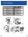
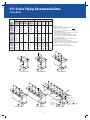
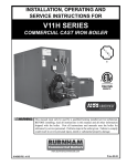
V11 Series
Cast Iron Commercial Water or Steam Boiler
837 to 5733 MBH Input
Oil, Gas, or Oil/Gas Combination
30, 50, or 80 PSI
Cast Iron Sectional Design
Water or Steam
Top or Rear Venting
Exclusive Optional SBC Boiler Controlª
Ð M aximizes System Efficiency
1
V11 Series
Cast Iron Commercial Water or Steam Boiler
Your Commercial Heating Solution!
Available in twenty sizes with gross output ratings from
667to4551MBH,theV11Seriesiscommonlyusedin
schools, hospitals, and other large commercial applications
where comfort and reliability are critical. The product meets
theenergyefficiencyrequirementsofASHRAE90.1with
combustion efficiencies up to 85%.
Installation & Service Flexibility
Cast iron construction, ease of assembly, two venting options,
andstringenttestingmethodsmaketheV11Seriesboilerby
Burnham Commercial your commercial heating solution.
• Hassle-free Section Assembly
ThecastironsectionaldesignoftheV11boilermakesiteasyto
maneuver through doorways and into the boiler room. In addition to being shipped as loose sections, the boiler is available
with factory-assembled sections or as a completely packaged
and fire-tested unit.
V11boilersectionshavereinforcedlugsthatareused
to assemble the sections with individual draw rods
resulting in fast, strain-free assembly.
American-Made Cast Iron ConstructionÐ
BC25-HSi
Burnham CommercialÕ s unique
BC25-HSicastironformulahas
an extremely high silicon content,
making it stronger and more
flexible than the iron used in
competitor's boiler sections. It offers
better thermal shock resistance and
greater heat transfer capabilities
than other cast iron products.
BC25-HSi'spropertiesallowBurnhamCommercialto
maintain the highest level of quality from start to finish, and
provide a product that is optimized
for hydronic heating applications.
The sections can be assembled using two common
toolsÑ a 3/4" drive ratchet with a 1-1/16" deep socket
and wrench. The sections are surface ground to ensure
smooth surface mating. An elastic sealant and fiberglass
rope are used on all section joints for a completely sealed
and pressure-tight assembly.
• extensive Testing Methods
Each boiler section is hydrostatically tested at 2-1/2 times
theratedworkingpressureatthefoundry.Factory-
assembled sections are tested a second time at 1.5 times the
rated working pressure.
• Manufactured with Quality
Cast iron sections are produced at
BurnhamFoundryLLCinOhio, ensuring quality and availability of
boiler sections.
• Rear or Top Venting
Asaforceddraftboiler,theV11
provides optimum draft for controlled
efficiency, eliminating the need for
high chimneys or induced draft fans.
AuniquefeatureoftheV11boiler
is that it can be vented from the
rear or the top. This enables easy
chimney or sidewall venting for
maximum installation flexibility.
Top outlet venting saves floor space
and reduces installation time and
materials. A plugged tapping is
provided to take flue outlet pressure
readings.
• Cast Iron nipple Difference
V11sectionsareheldtogether
using cast iron nipples, which
are well known as being of the
highest standard for boiler
construction. Unlike gaskets used
by many other boiler
manufacturers, cast iron nipples are impervious to flue
gases, oils, petroleum-based chemicals and other
contaminants, which means fewer costly repairs and a
longer lasting boiler.
2
Commitment to Quality
Burnham Commercial, "America's Boiler Company," has earned
a reputation for quality and dependability. Built for a variety of
applications,theV11Seriesisrightforyournextjob.
Top or Rear Outlet
with adjustable lock-type damper (not
shown); includes plugged tapping for outlet
pressure readings
Front Mounted Controls
for easy adjustment
and maintenance
Aluminized
Steel Canopy
Burner Mounting plate
with flame observation port
Cast Iron nipples
ensure the integrity of the
section assembly and resist
petroleum based chemicals
and flue gases
Removable Side Jacket panels
Easy access to all cleanouts
and flue surfaces
Cast Iron Sections
Verticalfluedesignwith
pinned heating surface for
maximum heat extraction
4 Burner
Manufacturers
Rear Observation port
Optionstobest
fit your needs
Includes plugged tapping
for over-fire draft readings
Individual Draw Rods
Wet Base
with reinforced lugs for
strain free assembly
Side wall insulation
creates improved
thermal circulation
Optional
Tankless Heater
Providesdomestichotwater
Also AvailableÉ
SBC
TM
Integrated Boiler Control System
Burnham CommercialÕ s SBC is a complete boiler
monitoring and automation system. Available as an option, this exclusive feature
wasdesignedanddevelopedbyBurnhamCommercial’sengineersandisavailableONLY
on Burnham Commercial products.
SBC Exclusives
Designedtomaximizesystemefficiency
and minimize energy usage
Easily connected to building management
systems
Provencontrolplatform,usedsuccessfully
for years at other Burnham companies
Fail-safedesigninsuresboileroperation
• AdvancedAdaptability
• Peer-To-PeerNetwork
•Fail-Safe System Operations
• BoilerMonitoring&DiagnosticDisplays
• ModulationRateandOn/OffModes
• Outdoor Air Temperature Reset
• Warm Weather Shutdown (WWSD)
• Domestic Hot Water Priority (DHWP)
• System Control Outputs
3
The SBC Boiler
Control SystemÉ
Only available
from Burnham
Commercial!
V11 Series Dimensions
BURneR DIMenSIOn - 'M' *
BOILeR
MODeL
V1104
V1105
V1106
V1107
V1108
V1109
V1110
V1111
V1112
V1113
V1114
V1115
V1116
V1117
V1118
V1119
V1120
V1121
V1122
V1123
nUMBeR
OF
SeCTIOnS
4
5
6
7
8
9
10
11
12
13
14
15
16
17
18
19
20
21
22
23
BeCKeTT
'A'
26-5/8
32-3/4
38-7/8
45
51-1/8
57-1/4
63-3/8
69-1/2
75-5/8
81-3/4
87-7/8
94
100-1/8
106-1/4
112-3/8
118-1/2
124-5/8
130-3/4
136-7/8
143
'B'
18-7/8
25
31-1/8
37-1/4
43-3/8
49-1/2
55-5/8
61-3/4
67-7/8
74
80-1/8
86-1/4
92-3/8
98-1/2
104-5/8
110-3/4
116-7/8
123
129-1/8
135-1/4
'C'
Ñ
Ñ
31-1/8
37-1/4
43-3/8
49-1/2
24-3/4
37
37
37
24-3/4
24-3/4
30-7/8
30-7/8
30-7/8
30-7/8
30-7/8
30-7/8
30-7/8
30-7/8
'D'
Ñ
Ñ
Ñ
Ñ
Ñ
Ñ
30-7/8
24-3/4
30-7/8
37
24-1/2
24-1/2
36-3/4
36-3/4
24-1/2
24-1/2
24-1/2
24-1/2
24-1/2
24-1/2
'e'
Ñ
Ñ
Ñ
Ñ
Ñ
Ñ
Ñ
Ñ
Ñ
Ñ
30-7/8
37
24-3/4
30-7/8
24-1/2
24-1/2
36-3/4
36-3/4
24-1/2
24-1/2
'F'
Ñ
Ñ
Ñ
Ñ
Ñ
Ñ
Ñ
Ñ
Ñ
Ñ
Ñ
Ñ
Ñ
Ñ
24-3/4
30-7/8
24-3/4
30-7/8
24-1/2
24-1/2
'G'
'H'
Ñ
13-13/16
Ñ
19-15/16
Ñ
26-1/16
Ñ
32-3/16
Ñ
38-5/16
Ñ
44-7/16
Ñ
50-9/16
Ñ
56-11/16
Ñ
56-5/8
Ñ
53-5/16
Ñ
53-5/16
Ñ
53-5/16
Ñ
53-5/16
Ñ
53-5/16
Ñ
53-5/16
Ñ
53-5/16
Ñ
53-5/16
Ñ
53-5/16
24-3/4 53-5/16
30-7/8 53-5/16
'J'
55
55
55
54
54
54
53
53
53
53
52
52
52
52
51
51
51
51
50
50
all dimensions in inches
* Burnercontrolpanelconfigurationmaychangethisdimension
FRONT
OBSERVATION
PORT
4
'K'
8
8
8
10
10
10
12
12
12
12
14
14
14
14
16
16
16
16
18
18
'L'
1
2
2
3
3
4
4
4
5
5
5
6
6
6
7
7
8
8
9
9
CF
24-3/4
24-3/4
24-3/4
24-1/4
24-1/4
24-1/4
24-1/4
24-1/4
25-3/4
25-3/4
27
27
26
Ñ
Ñ
Ñ
Ñ
Ñ
Ñ
Ñ
CG
21-3/4
21-3/4
28-3/4
29-1/4
29-1/4
29-1/4
29-1/4
29-5/8
29-5/8
29-5/8
29-5/8
29-5/8
29-5/8
29-5/8
29-5/8
29-5/8
Ñ
Ñ
Ñ
Ñ
pOWeRFLAMe WeBSTeR
CARLIn
Ñ
19-3/4
19-3/4
20-1/2
20-1/2
20-1/2
25-5/8
25-5/8
25-5/8
26-1/8
26-1/8
26-1/8
26-1/8
26-1/8
Ñ
Ñ
Ñ
Ñ
Ñ
Ñ
CR
30
30
35
35
35
35
35
40
40
40
40
40
40
40
40
40
40
40
46
46
JR**
20-1/4
20-1/4
23-3/4
23-3/4
23-3/4
Ñ
Ñ
Ñ
Ñ
Ñ
Ñ
Ñ
Ñ
Ñ
Ñ
Ñ
Ñ
Ñ
Ñ
Ñ
JB
25
25
25
25
25
25
25
29
29
29
29
29
29
29
29
29
29
29
29
29
AppROX.
WeIGHT OF
SeCTIOn
(Assembly Only)
1833
2226
2618
3010
3403
3795
4188
4580
4972
5365
5757
6150
6542
6934
7327
7719
8112
8504
8896
9289
V11 Series Piping Recommendations
Water Boiler
pipe Sizing and notes
nOTeS:
1. Allpipingisschedule40.
2. Pipesizelistedarebasedona20°For40°F
differential (temperature drop). Select one to match application.
3. Whenspecifiedreturnpipingsizeislessthan3",
install 3" x 12" nipple and appropriate size bell reducer
directly into boiler return tapping as shown.
4. Drainvalve-ballvalvepreferable,gatevalveacceptable
alternative (supplied by others).
MinimumvalvesizeperASMEcodeis3/4"NPT.
5. Swing joints on two riser systems may be piped over the
top of the boiler if space is limited.
6. Boilers require protection from flue gas condensation and thermal
shockwhenoperatingbelow135°Freturnwatertemperatures
BOILeR
MODeL
V1104
V1105
V1106
V1107
V1108
V1109
V1110
V1111
V1112
V1113
V1114
V1115
V1116
V1117
V1118
V1119
V1120
V1121
V1122
V1123
SUppLy pIpInG SIZe In InCHeS
(1B)
(1A)
SUppLy RISeR
SUppLy
(1)
(QTy.) SIZe
HeADeR
SUppLy
20¡ F 40¡ F 20¡ F 40¡ F 20¡ F 40¡ F
DROp DROp DROp DROp DROp DROp
Ñ
Ñ
Ñ
Ñ
2
2-1/2
Ñ
Ñ
Ñ
Ñ
2
2-1/2
Ñ
Ñ
Ñ
Ñ
2
2-1/2
Ñ
Ñ
Ñ
Ñ
2
3
Ñ
Ñ
Ñ
Ñ
2
3
Ñ
Ñ
Ñ
Ñ
2-1/2
4
Ñ
Ñ
Ñ
Ñ
2-1/2
4
Ñ
Ñ
Ñ
Ñ
2-1/2
4
Ñ
Ñ
Ñ
Ñ
3
4
Ñ
Ñ
Ñ
Ñ
3
4
Ñ
Ñ
Ñ
Ñ
3
4
Ñ
Ñ
Ñ
Ñ
3
4
Ñ
(2) 3
Ñ
3
3
5
Ñ
(2) 3
Ñ
3
3
5
Ñ
(2) 4
Ñ
4
4
5
Ñ
(2) 4
Ñ
4
4
5
Ñ
(2) 4
Ñ
4
4
5
Ñ
(2) 4
Ñ
4
4
5
Ñ
(2) 4
Ñ
4
4
5
Ñ
(2) 4
Ñ
4
4
5
5
ReTURn pIpInG SIZe In InCHeS
(2B)
(2A)
ReTURn BRAnCH
ReTURn
(2)
(QTy.) SIZe
HeADeR
ReTURn
20¡ F 40¡ F 20¡ F 40¡ F
20¡ F
40¡ F
DROp DROp DROp DROp DROp
DROp
Ñ
Ñ
Ñ
Ñ
2
2-1/2
Ñ
Ñ
Ñ
Ñ
2
2-1/2
Ñ
Ñ
Ñ
Ñ
2
2-1/2
Ñ
Ñ
Ñ
Ñ
2
3
Ñ
Ñ
Ñ
Ñ
2
3
Ñ
(2) 3
Ñ
3
2-1/2
4
Ñ
(2) 3
Ñ
3
2-1/2
4
Ñ
(2) 3
Ñ
3
2-1/2
4
Ñ
(2) 3
Ñ
3
3
4
Ñ
(2) 3
Ñ
3
3
4
Ñ
(2) 3
Ñ
3
3
4
Ñ
(2)
3
Ñ
3
3
4
Ñ
(2) 3
Ñ
3
3
5
Ñ
(2) 3
Ñ
3
3
5
(2) 3
(3) 3
3
4
4
5
(2) 3
(3) 3
3
4
4
5
(2) 3
(3) 3
3
4
4
5
(2) 3
(3) 3
3
5
4
5
(2) 3
(3) 3
3
5
4
5
(2) 3
(3) 3
3
5
4
5
V11 Series Piping Recommendations
Steam Boiler
pIpInG SIZe In InCHeS
(1)
RISeR
(2)
(3)
(4)
BOILeR
MODeL (QTy.) SIZe ReTURn HeADeR eQUALIZeR
2-1/2
4
2
(1) 4
V1104
2-1/2
4
2
(1) 4
V1105
2-1/2
6
2-1/2
(2) 4
V1106
2-1/2
6
2-1/2
(2) 4
V1107
2-1/2
6
2-1/2
(2) 4
V1108
2-1/2
6
2-1/2
(2) 4
V1109
2-1/2
6
2-1/2
(3) 4
V1110
4
8
3
(3) 4
V1111
4
8
3
(3) 4
V1112
4
8
3
(3) 4
V1113
4
8
3
(4) 4
V1114
4
8
3
(4) 4
V1115
4
8
3
(4) 4
V1116
4
8
3
(4) 4
V1117
4
8
3
(5) 4
V1118
4
10
3
(5) 4
V1119
4
10
3
(5) 4
V1120
4
10
3
(5) 4
V1121
4
10
3
(6) 4
V1122
4
10
3
(6) 4
V1123
RISeR SpACInG In InCHeS
ÔAÕ
Ñ
Ñ
31-1/8
37-1/4
43-3/8
49-1/2
24-3/4
37
37
37
24-3/4
24-3/4
30-7/8
30-7/8
30-7/8
30-7/8
30-7/8
30-7/8
30-7/8
30-7/8
ÔBÕ
Ñ
Ñ
Ñ
Ñ
Ñ
Ñ
30-7/8
24-3/4
30-7/8
37
24-1/2
24-1/2
36-3/4
36-3/4
24-1/2
24-1/2
24-1/2
24-1/2
24-1/2
24-1/2
ÔCÕ
Ñ
Ñ
Ñ
Ñ
Ñ
Ñ
Ñ
Ñ
Ñ
Ñ
30-7/8
37
24-3/4
30-7/8
24-1/2
24-1/2
36-3/4
36-3/4
24-1/2
24-1/2
ÔD Õ
Ô eÕ
Ñ
Ñ
Ñ
Ñ
Ñ
Ñ
Ñ
Ñ
Ñ
Ñ
Ñ
Ñ
Ñ
Ñ
Ñ
Ñ
Ñ
Ñ
Ñ
Ñ
Ñ
Ñ
Ñ
Ñ
Ñ
Ñ
Ñ
Ñ
Ñ
24-3/4
Ñ
30-7/8
Ñ
24-3/4
Ñ
30-7/8
24-1/2 24-3/4
24-1/2 30-7/8
nOTeS:
1. Allpipingisschedule40.
2. To prevent condensate from being trapped in header, do not reduce
equalizer elbow at header connection.
3. Drain/blowoffvalve—ballvalvepreferable,gatevalveacceptable
alternative (supplied by others).
-MinimumvalvesizeperASMEcodeis1"NPT(V1104-1106),1-1/4"
NPT(V1107-1112),1-1/2"NPT(V1113-1123).
- Increasing the valve size will improve the blowdown operation
- In all cases, piping connecting blowoff valve to boiler shall be full
size to the point of discharge.
4. Headerpipingmayberunoverthetopofboilerifspacedoesnot
allow for piping arrangement shown.
However,increasedservicerequirementswillresult.
5. Supply from boiler header must be connected between the first boiler
riserandtheheaderdrip(orhartfordloop).Donotconnectsupply
between risers or opposite end of boiler header.
6. Forpumpedreturnsystems,seeV11installationmanual.
'A'
'B'
'A'
V1106 THRU V1109
V1104 AND V1105
V1 110 THRU V1113
'A'
18"
MIN.
'A'
'A'
'B'
'B'
'C'
'C'
'B'
'C'
'D'
'D'
24"
MIN.
'E'
1
RISER
3
HEADER
4
EQUALIZER
CLOSE NIPPLE
V1114 THRU V1117
V1118 THRU V1121
6
WATER LINE
2" TO 4"
REAR OF BOILER
HARTFORD LOOP
(REQ'D ON GRAVITY
RETURN SYSTEM)
SUPPLY
(SEE NOTE 5)
2
RETURN
V1122 AND V1123
5
BLOWOFF/DRAIN VALVE
(SEE NOTE 3)
V11 Series Burner Schedule
OIL BURneRS
BeCKeTT
CARLIn
pOWeR FLAMe
WeBSTeR
BOILeR
nUMBeR
BURneR MODeL
H.p.
BURneR MODeL
H.p.
BURneR MODeL
H.p.
BURneR MODeL
H.p.
V1104
CF1400
1/2
Ñ
Ñ
CR1-OS
1/2
JB1O-03
1/3
V1105
CF1400
1/2
702CRD
1/2
CR1-OS
1/2
JB1O-03
1/3
V1106
CF1400
1/2
702CRD
1/2
CR2-OAS
3/4
JB1O-03
1/3
V1107
CF2300
3/4
801CRD
3/4
CR2-OAS
3/4
JB1O-05
1/2
V1108
CF2300
3/4
801CRD
3/4
CR2-OAS
3/4
JB1O-05
1/2
V1109
CF2300
3/4
801CRD
3/4
CR2-OAS
3/4
JB1O-07
3/4
V1110
CF2300
3/4
1050FFD
1
CR2-OAS
1-1/2
JB1O-07
3/4
V1111
CF2300
3/4
1050FFD
1
CR3-O
2
JB2O-10
1
V1112
CF2500
2
1050FFD
1-1/2
CR3-O
2
JB2O-10
1
V1113
CF2500
2
1050FFD
1-1/2
CR3-O
2
JB2O-10
1
V1114
CF3500
2
1150FFD
1-1/2
CR3-O
2
JB2O-10
1
V1115
CF3500
2
1150FFD
1-1/2
CR3-O
2
JB2O-10
1
V1116
CF3500
2
1150FFD
1-1/2
CR3-O
3
JB2O-15
1-1/2
V1117
Ñ
Ñ
1150FFD
1-1/2
CR3-O
3
JB2O-30
3
V1118
Ñ
Ñ
Ñ
Ñ
CR3-OB
3
JB2O-30
3
V1119
Ñ
Ñ
Ñ
Ñ
CR3-OB
3
JB2O-30
3
V1120
Ñ
Ñ
Ñ
Ñ
CR3-OB
3
JB2O-30
3
V1121
Ñ
Ñ
Ñ
Ñ
CR3-OB
3
JB2O-50
5
V1122
Ñ
Ñ
Ñ
Ñ
CR4-OA
5
JB2O-50
5
V1123
Ñ
Ñ
Ñ
Ñ
CR4-OA
5
JB2O-50
5
STANDARD BURNER MOTOR VOLTAGE: Beckett–CF1400,andCF2300are120/60/1.CF2500andCF3500are240/60/3.Carlin–Allsizes240/60/1.power Flame–CR1-OSis
120/60/1.CR2-OASis240/60/1.Allothersare240/60/3.Webster–JB10-03,JB10-05andJB10-07are120/60/1.JB20-10is240/60/1.Allothersare240/60/3.
GAS BURneRS*
BeCKeTT
pOWeR FLAMe - 'CR'= pOWeR FLAMe - 'JR'=
WeBSTeR
BOILeR
BURneR
MIn. GAS
BURneR
BURneR
BURneR
MIn. GAS
nUMBeR
MODeL
H.p.
pReSS. (In.)
MODeL
H.p.
MODeL
H.p.
MODeL
H.p. pReSS. (In.)
V1104
CG10.6S
1/3
4.6
CR1-G-12
1/3
JR30A-10
1/3
JB1G-03
1/3
6
V1105
CG10.6S
1/3
6.6
CR1-G-12
1/2
JR30A-12
1/3
JB1G-03
1/3
4
V1106
CG15.4S
1/2
6.2
CR2-G-15
1/2
JR50A-15
1/3
JB1G-03
1/3
6
V1107
CG25.2S
3/4
5.2
CR2-G-15
1/2
JR50A-15
1/2
JB1G-05
1/2
5
V1108
CG25.3S
3/4
5.0
CR2-G-15
1/2
JR50A-15
1/2
JB1G-05
1/2
5
V1109
CG25.4S
3/4
5.2
CR2-G-15
1/2
Ñ
Ñ
JB1G-07
3/4
8
V1110
CG25.5S
3/4
5.2
CR2-G-20A
1
Ñ
Ñ
JB1G-07
3/4
8
V1111
CG50.2S
2
5.7
CR3-G-20
1-1/2
Ñ
Ñ
JB2G-10
1
8
V1112
CG50.3S
2
4.3
CR3-G-20
1-1/2
Ñ
Ñ
JB2G-10
1
6
V1113
CG50.3S
2
5.7
CR3-G-20
1-1/2
Ñ
Ñ
JB2G-10
1
7
V1114
CG50.4S
2
5.7
CR3-G-20
1-1/2
Ñ
Ñ
JB2G-15
1-1/2
8
V1115
CG50.5S
2
5.0
CR3-G-20
1-1/2
Ñ
Ñ
JB2G-30
3
8
V1116
CG50.5S
2
5.3
CR3-G-25
3
Ñ
Ñ
JB2G-30
3
8
V1117
CG50.5S
2
6.1
CR3-G-25
3
Ñ
Ñ
JB2G-30
3
9
V1118
CG50.5S
2
6.9
CR3-G-25B
3
Ñ
Ñ
JB2G-30
3
10
V1119
CG50.5S
2
7.3
CR3-G-25B
3
Ñ
Ñ
JB2G-30
3
11
V1120
Ñ
Ñ
Ñ
CR3-G-25B
3
Ñ
Ñ
JB2G-30
3
12
V1121
Ñ
Ñ
Ñ
CR3-G-25B
3
Ñ
Ñ
JB2G-50
5
14
V1122
Ñ
Ñ
Ñ
CR4-G-25
3
Ñ
Ñ
JB2G-50
5
15
V1123
Ñ
Ñ
Ñ
CR4-G-25
3
Ñ
Ñ
JB2G-50
5
16
STANDARD BURNER MOTOR VOLTAGE: power Flame C Series–CR1-G-12andCR2-G-15are120/60/1.CR2-G-20Ais240/60/1.Allothersare240/60/3.power Flame JR Series
–Allburnersare120/60/1.Webster–JB1G-03,JB1G-05andJB1G-07are120/60/1.JB2G-10is240/60/1.Allothersare240/60/3.
*Forinletgasconnectionsize,seeGas/OilBurnerChart=Forminimumgaspressurerequirements,seeGas/OilBurnerChart.
GAS/OIL BURneRS
pOWeR FLAMe - 'CR' SeRIeS
WeBSTeR
BOILeR
BURneR
InLeT GAS
MIn. GAS
BURneR
InLeT GAS
MIn. GAS
nUMBeR
MODeL
H.p. COnneCTIOn (In.) pReSS. (In.)
MODeL
H.p. COnneCTIOn (In.) pReSS. (In.)
V1104
CR1-GO-12
1/2
1
4.7
JB1C-03
1/3
1
7.0
V1105
CR1-GO-12
1/2
1
4.8
JB1C-03
1/3
1-1/4
4.9
V1106
CR2-GO-15
3/4
1
5.4
JB1C-03
1/3
1-1/4
7.0
V1107
CR2-GO-15
3/4
1
6.4
JB1C-05
1/2
1-1/4
6.2
V1108
CR2-GO-15
3/4
1
7.5
JB1C-05
1/2
1-1/2
6.9
V1109
CR2-GO-15
3/4
1-1/4
6.4
JB1C-07
3/4
1-1/2
7.0
V1110
CR2-GO-20A 1-1/2
1-1/4
5.8
JB1C-07
3/4
1-1/2
7.0
V1111
CR3-GO-20
2
2
5.8
JB2C-10
1
2
6.3
V1112
CR3-GO-20
2
1-1/2
6.0
JB2C-10
1
2
5.6
V1113
CR3-GO-20
2
1-1/2
6.8
JB2C-10
1
2
6.3
V1114
CR3-GO-20
2
1-1/2
7.4
JB2C-10
1
2
7.0
V1115
CR3-GO-20
2
1-1/2
7.3
JB2C-10
1
2
6.8
V1116
CR3-GO-25
3
2
6.6
JB2C-15 1-1/2
2
7.0
V1117
CR3-GO-25
3
2
7.1
JB2C-30
3
2
7.3
V1118
CR3-GO-25B
3
2
7.7
JB2C-30
3
2-1/2
8.1
V1119
CR3-GO-25B
3
2-1/2
6.5
JB2C-30
3
2-1/2
9.2
V1120
CR3-GO-25B
3
2-1/2
7.0
JB2C-30
3
2-1/2
10.0
V1121
CR3-GO-25B
3
2-1/2
7.0
JB2C-50
5
2-1/2
11.0
V1122
CR4-GO-25
5
2-1/2
6.3
JB2C-50
5
2-1/2
12.4
V1123
CR4-GO-25
5
2-1/2
6.9
JB2C-50
5
2-1/2
13.1
STANDARD BURNER MOTOR VOLTAGE: power Flame-CR1-GO-12is120/60/1.CR-2-GO-15andCR2-GO-20Aare240/60/1.Allothersare240/60/3.Webster–JB1C-03,JB1C05,JB1C-07are120/60/1.JB2C-10is240/60/1.Allothersare240/60/3.
**Forminimumgaspressurerequirements,seeGasBurnerChart.NOTES:1.TheminimumgaspressuresshownareforstandardULburnerswiththestandardfiringsequence.IRI,FM
andCSD-1requirementsmayresultindifferentpressuresandprices.
7
Specifications
V11 RATInGS
BOILeR
MODeL
(1)
V1104
V1105
V1106
V1107
V1108
V1109
V1110
V1111
V1112
V1113
V1114
V1115
V1116
V1117
V1118
V1119
V1120
V1121
V1122
V1123
GROSS
OUTpUT
MBH
BOILeR
(2)
H.p.
667
19.9
857
25.6
1069
31.9
1281
38.3
1517
45.3
1729
51.7
1941
58.0
2154
64.3
2334
69.7
2503
74.8
2730
81.6
2957
88.3
3129
93.4
3353
100.2
3580
106.9
3739
111.7
3957
118.2
4174
124.7
4334
129.5
4551
136.0
I=B=R neT RATInG (3)
STeAM
MBH
500
643
802
963
1159
1335
1507
1672
1812
1943
2120
2296
2427
2603
2780
2903
3072
3241
3365
3533
SQ. FT.
2083
2679
3342
4013
4829
5563
6279
6967
7550
8096
8833
9567
10113
10846
11583
12096
12800
13504
14021
14721
WATeR
MBH
580
745
930
1114
1319
1503
1688
1873
2030
2177
2374
2571
2718
2916
3113
3251
3441
3630
3769
3957
BURneR InpUT
OIL
GpH
(4)
5.8
7.4
9.2
11.0
13.0
14.8
16.6
18.4
20.0
21.5
23.5
25.5
27.0
29.0
31.0
32.5
34.5
36.5
38.0
40.0
GAS
MBH
837
1068
1328
1588
1876
2136
2396
2656
2887
3103
3392
3680
3897
4186
4474
4691
4979
5268
5485
5733
neT
FIReBOX
VOLUMe
(In. WTR.
COLUMn)
7.9
10.6
13.2
15.9
18.5
21.1
23.8
26.5
29.1
31.8
34.4
37.1
39.7
42.4
45.0
47.7
50.3
53.0
55.6
58.3
pReSSURe
In
FIReBOX
(In. WTR.
COLUMn)
.35
.36
.37
.42
.42
.39
.42
.40
.42
.40
.38
.36
.38
.41
.39
.38
.38
.40
.41
.43
I=B=R
VenT DIA.
(In.)
8
8
8
10
10
10
12
12
12
12
14
14
14
14
16
16
16
16
18
18
AppROX.
SHIppInG
AnD LIFTInG
WeIGHT
(LBS.)
2105
2510
2920
3325
3733
4147
4557
4964
5374
5771
6184
6601
7008
7417
7823
8231
8638
9053
9456
9865
1. Suffix“S”indicatessteamboiler,“W”indicateswaterboiler.Suffix“G”indicatesgas-fired,“O”indicatesoilfiredand“GO”indicatescombination
gas/oil fired.
2. Boilerratingsarebasedon13%CO2onoil;10.0%CO2ongas,and+.10in.watercolumnpressureatboilerflueoutlet.
3. I=B=Rnetratingsshownarebasedonpipingandpickupallowanceswhichvaryfrom1.333to1.288forsteamand1.15forwater.Consult
manufacturer for installations having unusual piping and pick up requirements, such as intermittent system operation, extensive piping systems, etc.
4. TheI=B=RburnercapacityinGPHisbasedonoilhavingaheatvalueof140,000BTUpergallon.
Ratingsshownaboveapplytoaltitudesupto1000feetforoiland2000feetforgas.Foraltitudesabovethoseindicated,theratingsshouldbereduced
attherateof4%foreach1000feetabovesealevel.
nOTe: Maximumallowableworkingpressure(MAWP):
Steam: 15PSI
Water–USA:
80PSI(Standardreliefvalveprovidedis50PSI)(80PSI/30PSIOptional)
Water–Canada: 50PSI(Standardreliefvalveprovidedis50PSI)(30PSIOptional)
STAnDARD eQUIpMenT
ALL BOILeRS:Sectionsunassembled,flushinsulatedjacket,burnermountingplate,rearobservationportcover,firewallplates,targetwall(V1104-1106
only), rear flue outlet damper (top outlet optional), flue canopy, trim, and miscellaneous plugs, bushing and fittings
STeAM TRIM:15PSIsafetyvalve,L404Fpressuretrol,gaugeglassassembly,steamgauge
WATeR TRIM:50PSIsafetyreliefvalve,L4006Ahighlimit,pressuretemperaturegauge
OIL BOILeRS:Flangemountedflameretentionoilburnerfurnishedwith2stagefuelunit,primarycontrolanddualoilvalves
GAS BOILeRS:FlangemountedgasburnerwithstandardcontrolsmeetingthelatestULrequirements,dualgasvalves,gas-electricignitionwithproven
gaspilot,flamerodonJRburner,ultravioletflamedetectoronothers,electronicprogrammingcontrolsandcomponentsarefactorywiredinaburner
mountedcontrolpanel(exceptJR-panelavailableasanoption)
GAS/OIL BURneRS:Flangemountedcombinationgas/oilburnerwithstandardcontrolsmeetinglatestULrequirements,manuallyoperatedfueltransfer
switch for dual fuel changeover, dual gas valves and oil valves, electric ignition with proven gas pilot on both fuels (direct spark ignition of oil is optional), ultra-violet flame detector, electronic programming controls and components are factory wired in a burner mounted control panel
OpTIOnAL eQUIpMenT
Assembled sections; completely packaged (includes manual reset high limit and manual reset low water cutoff); packaged and fire-tested; top outlet flue
damper;tanklessheaters;sideinspectiontappingswithbrassplugs;pressurereliefdoor;30PSIand80PSIsafetyreliefvalves;combustionandhydronic
controlstomeetspecialapplicationsincludingF.M.,I.R.I.,andASMECSD-1.
BurnhamCommercial-Lancaster,PA
Phone:-888-791-3790
www.burnhamcommercial.com
8