1
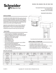
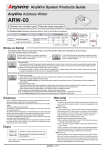
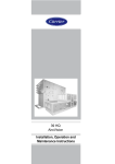
39 HQ
Airovision Air Handling Units
Installation, operation and
maintenance instructions
CONTENTS
1
- SAFETY CONSIDERATIONS ...............................................................................................................4
1.1
1.2
1.3
1.4
-
2
- TRANSPORT AND LIFTING INSTRUCTIONS ..................................................................................5
2.1
2.2
2.3
2.4
2.5
-
3
- CHECKLIST OF START-UP CHECK POINTS....................................................................................7
3.1
- Checklist of start-up check points ....................................………………………………………………………………7
4
- START-UP INSTRUCTIONS .................................................................................................................9
4.1
4.11
4.12
4.13
- Casing...........................................................................…………………………………………………………………9
4.1.1 - Casing panels .................................................……………………………………………………………………9
4.1.2 - Doors and access covers ............................................……………………………………………………………9
4.1.3 - Flexible connections ....................................…………………………………………………………………...…9
4.1.4 - Earthing .........................................................................................................................................................9
4.1.5 - AHU installation and connection .............................……………………………………………………………9
- Dampers ............................................................................……………………………………………………………10
- Air filters...........................................................................................…………………………………………………10
- Heaters ......................................................................………………………………………………………………….10
4.4.1 - General ...........................................................………………………………………………………………….10
4.4.2 - Electric heaters ..................................................................…………………………….………………………10
4.4.3 - Steam heaters ..........................................................……………………………………………………………10
- Coolers....................................................................................................................................................................11
- Heat recovery wheel ..................................................…………………………………………………………………..11
- Plate heat exchanger .......................................................………………………………………………………………11
- Direct steam humidification ..........................................................……………………………………………………11
- Electrical steam humidification ...........................................................……………………………………………….12
- Water humidifiers ......................................................................………………………………………………………12
4.10.1 - Spray humidifier ...........................................................………………………………………………………12
4.10.2 - Infrasonic humidifier...........................…………………………………………………………………………12
- Fan..........................................................................……………………………………………………………………12
- Sound attenuator................................................................……………………………………………………………13
- Lighting ..................................................................……………………………………………………………………13
5
- MAINTENANCE PLAN .......................................................................................................................14
5.1
- Checklist of check points and maintenance intervals .............…………………………………………………………14
4.2
4.3
4.4
4.5
4.6
4.7
4.8
4.9
4.10
General .....................................................................................................................................................................4
Applications..............................................................................................................................................................4
Instruction types .......................................................................................................................................................4
Disposal of parts/materials .......................................................................................................................................5
General ....................................................................…………….………………………………………………………5
Transport and storage .................................................................………………………………………………………5
Transport protection .......................................................................……………………………………………………6
Vertical transport ......................................................................………………………………………………………..6
Horizontal transport ........................................................………………………………………………………………6
CONTENTS (continued)
6
- MAINTENANCE AND OPERATING INSTRUCTIONS....................................................................16
6.1
6.2
- General ...................................................................……………………………………………………………………16
- Casing panels .........................................................…………………………………………………………………….16
6.2.1 - Inside installation ....................................................……………………………………………………………16
6.2.2 - Outside installation ..................................................…………………………………………………………...16
- Doors and access covers.........................................................…………………………………………………………16
- Flexible connections ..................................................……………………….…………………………………………16
- Earthing ..................................................................……………………………………………………………………16
- Dampers ................................................................................…………………………………………………………16
- Outside air intake...................................................................…………………………………………………………16
- Filters .........................................................................…………………………………………………………………16
- Heaters ...........................................................................………………………………………………………………16
6.9.1 - Water, glycol and steam coils............................................................................………………………………16
6.9.2 - Electric heaters ......................................................................…………………………………………………17
- Coolers....................................................................……………………………………………………………………17
- Heat recovery wheel........................................................………………………………………………………………17
- Plate heat exchanger...............................................................…………………………………………………………17
- Water humidification....................................................................…….………………………………………………17
6.13.1 - Steam humidification ..............................................…………………………………………………………..17
6.13.2 - Spray humidifier ....................................................……………………………………………………………17
6.13.3 - Infrasonic humidifier ............................................…………………………………………………………….18
- Fan.........................................................................…………………………………………………………………….18
6.14.1 - General.......................................................................................................................................................18
6.14.2 - Bearings......................................................................................................................................................18
6.14.3 - Transmission ..............................................................................................................................................18
- Sound attenuator ....................................................................................................................................................18
6.3
6.4
6.5
6.6
6.7
6.8
6.9
6.10
6.11
6.12
6.13
6.14
6.15
1 - SAFETY CONSIDERATIONS
1.1 - General
The 39HQ air handling units (AHUs) has been designed
and manufactured in accordance with the CE machine
directive EN292. In order to guarantee safe operation and
use of the unit, please carefully read and observe the
instructions in this document and pay special attention to
the warnings that apply to this unit. Any modifications in
the design and/or installation of the AHU that are carried
out without discussion with Carrier Holland Heating and
without advance written agreement will result in the loss of
the right to any warranty claims and any claim for injury to
personnel as a result of these modifications.
Maintenance procedures may only be carried out by
qualified personnel.
Heating and cooling elements are manufactured and
supplied in accordance with guidelines of the Pressure
Equipment Directive (PED).
1.2 - Applications
Earthing
This pictogram indicates where the AHU must be earthed
and is on one of the support beams beneath the casing in
the fan section.
- The electrical components in the AHU must be earthed,
except for components with double insulation and/or
components with a supply voltage below 50 V.
- The electrical components must be installed in accordance
with national and local regulations.
Rotating parts
This pictogram indicates that there are rotating parts behind
this access cover, door or panel which may cause injury. The
components that include rotating parts are the fan and heat
recovery wheel. If there are special customer-specific
components behind doors, access covers or panels that
include rotating parts and pose a potential risk, this is also
indicated by this pictogram.
The AHU is designed for the movement and conditioning
of air, unless otherwise agreed during the design stage.
1.3 - Instruction types
The following warning pictograms and labels with text are
used.
Lifting point
This pictogram shows where the AHU must be lifted and is
positioned on the support beam.
Lifting prohibited
This pictogram shows that no horizontal transport devices
must be placed under this frame section, such as pallet
lifters or the forks of fork lift trucks. It is also forbidden to
place lifting devices for transport and storage under this
frame element.
4
Hot surfaces
This pictogram indicates that there are components behind
this access cover, door or panel that can cause serious burns
when touched.
The components that may have hot surfaces are the steam
humidifier, steam heater and the electric heater. If there are
special special customer-specific components behind doors,
access covers or panels that have hot surfaces and pose a
potential risk, this is also indicated by this pictogram.
Electrical voltage
This pictogram indicates that there are electrical components
behind this access cover, door or panel that may be dangerous
for the user/installer. Only personnel qualified in accordance
with NEN 3140 is permitted to carry out work on these
components. The pictogram is attached to the access cover
for the electric heater control box.
Lifting and transport
An instruction is attached to the AHU that describes the
procedures that must be followed for lifting and transport.
The following chapter contains further details.
1.4 - Disposal of parts/materials
- The packaging material must be disposed of in a responsible
manner and in accordance with local regulations.
- Components that are replaced, must be disposed of as
described above.
2 - TRANSPORT AND LIFTING INSTRUCTIONS
2.1 - General
Removal of transport brackets
This pictogram is located at the bottom of the fan section. It
indicates that the transport brackets must be removed during
commissioning before the fan is started up.
.
Verwijder transportbeugels voor opstarten ventilator.
Remove transport brackets before starting up the fan.
Retirer les fixations de transport avant démarrage.
Central data
This label contains the data for the AHU, such as order
number, position number etc. If present, the label is normally
located on the access cover or the door of the fan assembly.
Transport and lifting of the AHU must always be in
accordance with the instructions below. If these instructions
are not observed, irreparable damage may occur to the unit,
and people in the immediate vicinity of the unit are also
endangered. Carrier Holland Heating does not accept any
responsibility if these instructions are not observed. Transport
and lifting must be carried out by qualified personnel. The
AHU must only be lifted with lifting bars supplied by
Carrier Holland Heating. Lifting must be carried out in
accordance with local regulations and with the help of
certified lifting aids.
2.2 - Transport and storage
Lifting of the AHU is only permitted under the designated
lifting points. Lifting under the cross beams is prohibited.
This applies to transport as well as storage, and is indicated
on the cross beam with the following label.
Opening the fan door
This pictogram is positioned on the outside of the door or
access cover of the fan assembly. This pictogram warns that
the fan must have been switched off and deenergised for a
minimum of two minutes before the door or access cover is
opened.
! WARNING!
Before opening doors, switch off and deenergise the
fan, and ensure that it has stopped rotating.
(minimum of 2 minutes)
Caution: All doors and access covers must be closed before
starting up the AHU.
5
2.3 - Roof edge protection during transport (outside
installation)
For offloading as well as hoisting lifting cables can be
attached to the lifting bars. Evenly positioned spacer bars
should be used between the lifting cables to prevent damage
to the top of the unit and ensure that no excess pressure is
applied to the side panels. For hoisting please ensure that
the weight is evenly distributed.
Roof edge transport protection
During transport by truck the units are attached to the
loading surface with tie ropes, pulled across the unit towards
the side edges of the truck.
On external units, to protect the roof edge from distortion
by the tie ropes protection plates are added.
The AHU should not be lifted or moved under the cross
beams. This is indicated by the label below.
For safety reasons these protection plates must be fixed.
This is done by attaching them with self-tapping screws to
the roof edge.
Make sure that the protection plates are removed after
arrival on site before the AHU is lifted.
2.4 - Offloading and hoisting
2.5 - Horizontal transport
Depending on the dimensions of the AHU and the situation
on site, the AHUs are supplied in previously agreed transport sections.
For horizontal movement pallet lifters or transport skids
can be placed under the installation frame or under the
lifting bars. It is important that these support the lifting
points. At no time should the cross beams at the ends of the
unit sections be used for jacking or tracking the AHU. FOR
HORIZONTAL TRANSPORT ALWAYS PROVIDE
SUPPORT UNDER THE LIFTING POINTS. The use of
bars as rollers can result in damage to the installation frame.
Before proceeding with the transport and installation of the
casing sections, always consult the applicable dimensional
drawing that give the dimensions and weights of the
sections, as well as the installation sequence.
The weight is given on each transport section. Each transport
section is equipped with a subframe with four lifting points.
These points are marked by the label shown below.
6
3 - CHECKLIST OF START-UP CHECK POINTS
3.1 - Checklist of start-up check points
The table below shows a general overview of the planning required to facilitate the installation of the AHU. The following
pages give a more detailed description of the individual components.
! Caution !
Before starting up the AHU ensure that the components have the correct connection voltage
and connect them in accordance with the regulations. The doors and access covers must be
closed and the AHU must be earthed.
FUNCTION
General
Indoor installation
Outdoor installation
COMPONENTS
CHECK POINTS
Internal and external panels
Internal and external panels
Joints
Doors/access covers
Flexible connections
Earthing
Damage
Damage
Cracks
Must be closed before start-up
Correct installation
Correct earthing in acordance with regulations
Correct operation
Correct operation
Correct filter type
Are the filters correctly installed
Correct operation
Correct operation/set-up
Correct connections
Leakage
Operation of frost protection thermostat
Correct connections/safety devices
Correct connections/safety devices
Leakage
Correct connections
Leakage
Correct alignment
Correct connection
Direction of rotation
Correct installation
Motor/belt/rotation control
Correct set-up
Correct operation
Correct operation
Correct connection
Correct alignment
Dampers
Actuators
Filters
Heaters
Pressure differential gauge
Pressure differential switch
Hot-water coil
Electric heater
Steam heater
Coolers
Heat recovery wheel
Plate heat exchanger
Cold-water coil
Droplet eliminator
Drain trap
Rotor
Sealing
Drive
Controller
Damper (if used)
Actuator (if used)
Drain trap
Droplet eliminator
Start-up
START-UP CHECK POINTS
7
Electrical steam
humidification
Water humdifiers
Fan
COMPONENTS
CHECK POINTS
Connections and fittings
Leakage
Actuator/valve
Check connection and operation
Connections and fittings
Leakage/operation
Electrical components
Check connection voltage
Check connection and operation
See documentation supplied
See documentation supplied
See documentation supplied
Remove
Spray humidifier
Infrasonic humidifier
Wet cell
Transport protection brackets
Fan housing and fan compartment
Motor
Drive belts
Flexible connections
Operating switch
Operating switch
Pressure switch
Sound attenuator
Lighting
8
Lamp
Switch
Remove obstacles and loose debris from the fan and
fan compartment
Check connection voltage
Check connection
Check all phases
Check tension
Correct installation
Check connection
Ensure switch is locked off during checks
Operation
Damage to splitters
Check connection voltage
Check connection
Start-up
FUNCTION
Direct steam
humidification
4 - START-UP INSTRUCTIONS
4.1.5 - AHU installation and connection
4.1 - Casing
The floor in the room where the AHU is installed must be
level and flat to prevent connection problems. Before the
units are placed against or on top of each other, the sealing
tape supplied must be attached between the casing sections.
The label with the unit data, such as order number, position
number etc. is ususally located on the acccess cover or door
of the fan compartment.
4.1.1 - Casing panels
Check the AHU panels for any damage. Any dirt or stains
must be removed from the surface to prevent possible longterm damage. Building debris left on the roof must be
removed. Dirt can be removed with water and a mild household soap solution. Damage can be repaired by thoroughly
cleaning the affected surface, then treat and paint as
necessary. If applicable check the sealing joints and repair if
required.
4.1.2 - Doors and access covers
Check the operation of door handles, locks and movement
of the hinges. For outside installation of the AHU check
the storm cord.
Caution: Doors and access covers must always be closed
before starting the unit.
4.1.3 - Flexible connections
Check that all flexible connections are attached to the AHU.
If necessary, tighten loose screws.
4.1.4 - Earthing
Ensure that the AHU has been earthed correctly and in
accordance with local regulations. A label on the support
frame indicates where the unit should be earthed.
Place the casing sections as close as possible together before
assembly. Pull the casing sections towards each other by
placing the lifting bars first in one and then in the other
casing section. Then pull both parts towards each other
using pull ropes.
The casing sections are connected with the frames and fixing
elements supplied. If the AHU is installed outside, the roof
connecting plate provided must be installed on the roof and
sealed.
Sealant
9
4.2 - Dampers
- Check if the actuator motor is installed in accordance
with the supplier’s instructions.
- Check if the correct angle has been set.
- Check if the dampers close properly.
- Check if the damper can open to the required angle.
- Check operation after the power has been restored
following a power cut. Some dampers must be open,
others must be closed.
Manual operation
- Ensure that the heater can supply heat to prevent frost
formation when the fan is started.
- Caution: When the coils are drained, no water must
remain in the circuits to prevent freezing at temperatures
below zero.
4.4.2 - Electric heaters
- Ensure that the heater has been connected in accordance
with the instructions of the supplier. The diagram is
located on the inside of the connection module.
- Check the heater current.
- Check if the safety devices shown in the wiring diagram
have been installed.
- Check if the heater has been earthed in accordance with
local instructions.
- The electric heater may only be switched on if the
minimum specified air flow rate across the heater exists.
- The electric heater must be switched off at least 5 minutes
before the AHU is switched off.
- Ensure that no objects have been left in the heater section.
- The following warning pictograms are attached to the
panel: electrical voltage and hot surface.
Actuator-assisted operation
4.3 - Air filters
- Check if the correct filters have been installed.
- Check if the filters have been installed correctly.
- Absolute filters are supplied separately, to prevent
contamination during transport and start-up. Insert the
absolute filters only after the unit has been cleaned.
- Set pressure switches or filter indicators, if used.
- Close the inspection door.
4.4 - HEATERS
4.4.1 - General
- Check connections in accordance with the dimensional
drawing.
- Check connections for leakage.
10
4.4.3 - Steam heaters
Steam heaters have surface temperatures above 100ºC.
Steam supply must be checked by qualified personnel.
- The steam heater may only be switched on if the
minimum specified air flow rate exists across the heater.
- Ensure that no objects have been left in the heater section.
- The steam heater must be switched off at least 5 minutes
before the AHU is switched off.
- The following warning pictogram is attached to the panel:
hot surface.
4.5 - Coolers
- Check the connections in accordance with the dimensional
drawing.
- Control the connections for leaks.
- Check drain trap. If CHH standard siphon trap is used,
check it has been correctly installed. Check if siphon
cover and ball have been correctly installed.
- Check if fins have been bent during transport. Correctly
straighten the fins.
- Check if the siphon has been correctly installed. Check if
siphon cover and ball have been correctly installed.
4.8 - Direct steam humidification
- Check if the droplet eliminator after the cooler has been
correctly installed.
- Check if fins have been bent during transport. Correctly
straighten the fins.
- If a cooling coil is incorporated, after several days of
cooling operation check the condensate drain and operation of the plastic siphon. If necessary clean the siphon.
4.6 - Heat recovery wheel
- Check that the wheel is rotating in the correct direction.
This is indicated by an arrow on the casing.
- Check if the wheel seals are fitting correctly.
- Check if belt tension is correct.
- Check if the motor and the rotation monitor have been
correctly connected.
- Check if the controller has been correctly connected and
set in accordance with the instructions of the supplier.
- Check if the rotor speed has been set correctly.
- The following warning pictogram is attached to the panel:
rotating parts.
- Check the fixing of the steam pipe.
- Check the steam supply and condensate drain pipes.
- For longer pipes install an extra condensate pan in
accordance with the instructions of the supplier.
- Check if the pollution trap has been installed.
- The condensate drain should not be without pressure in
accordance with the manufacturer’s instructions. Refer to
the instructions of the supplier.
- If the AHU has negative pressure, install a special siphon
ahead of the condensate drain.
- Before starting up the steam humidifier steam must be
introduced slowly into the system to bring the humidifier
to the correct operating temperature. Once the condensate
pipe has reached the operating temperature, start the actuator
motor electrically or pneumatically and set the desired
humidity level. Refer to the instructions of the supplier.
- A few days after starting up the unit clean the sieve of the
pollution trap and check the condensate drain. For casings
with negative pressure the operation of the negative
pressure system must be controlled with the check valve.
- The following warning pictogram is attached to the panel:
hot surface.
4.7 - Plate heat exchanger
Used if dampers are installed.
- Check if the actuator motor has been installed in
accordance with the instructions of the supplier.
- Check if the correct angle has been set.
- Check if the dampers close correctly.
- Check if the damper can open to the correct position.
- Check operation after the power has been restored
following a power cut. Some dampers must be open,
others must be closed.
4.9 - Electrical steam humidification
- Check the fixing of the steam generator.
- Check the steam supply and condensate drain pipes.
- The condensate drain should not be without pressure in
accordance with the manufacturer’s instructions. Refer to
the instructions of the supplier.
- If the AHU has negative pressure, install a special siphon
ahead of the condensate drain.
- Check the voltage and measure the total current draw.
11
- Connect the humidifier in accordance with the
instructions of the supplier.
- The following warning pictogram is attached to the panel:
hot surface.
- Check the direction of rotation of the impeller. The
direction is indicated on the casing by an arrow.
- Separately measure the current draw of the electric motor
for all phases. The current draw of all phases must be
approximately the same and agree with the data on the
name plate. Set the motor protection device to the
nominal value.
Caution: The air flow may cause stationary parts to move
(even a fan that is switched off)!
4.10 - WATER HUMIDIFIERS
4.10.1 - Spray humidifier
Refer to the instructions supplied by the supplier.
4.10.2 - Infrasonic humidifier
- Carefully read the instructions from the supplier. The
following points need extra attention.
- Check if connection voltage agrees with the unit voltage.
- Connect the unit according to the diagram supplied.
- Check that the drain is correctly connected.
- Check the connections of the high-pressure pipes. After
starting the unit ensure that the pipes do not rub against
anything.
- Check if the spray jets work correctly.
- Check the operation of the pressostats and the pressure.
- Check the water quality.
- The data for the belt type, belt tension, number of belts,
size and type of pulley is indicated on a label attached to
the fan housing.
- Check if the flexible connection is correctly installed.
- If used check the pressure switch and set the correct
pressure.
- Check the operation of the main switch. Caution: While
working on the fan the switch has to be locked open.
- The warning pictograms on rotating parts, electrical
voltage and opening doors are attached to the door. The
label to remove the transport brackets is located on the
floor of the fan section.
! Warning !
Before opening doors, switch off and deenergise the
fan, and ensure that it has stopped rotating.
(minimum of 2 minutes)
4.11 - Fan
Remove before transport
4.12 - Sound attenuator
- Check the splitters for damage.
4.13 - Lighting
- Check the connection voltage.
- Check the operation of the switch. The switch must be
connected in accordance with local regulations.
- Remove the transport brackets. This is indicated by a label
on the door.
- Check if the fan can move freely without obstructing the
frame, flexible connection or wiring.
- Check the connection voltage.
- Check and/or connect the motor in accordance with local
instructions and the data of the supplier.
12
5 - MAINTENANCE CHECKLIST
5.1 - Checklist for check points and maintenance intervals
The checklist contains a general overview of the planning that facilitates the inspections and maintenance of the AHU. On
the following pages there is a more detailed description of the individual components.
! Warning !
Remember to deenergise all components and to ensure that the fan has stopped rotating,
before the doors and access covers are opened before inspections and maintenance take place.
Depends on
supplier and
degree of
contamination
12 months
CHECK POINTS
6 months
COMPONENTS
3 months
FUNCTION
1 month
CHECK POINTS AND MAINTENANCE INTERVALS
Casing general
Indoor installation
Outdoor installation
Internal and external
panels
Internal panels
External panels
Contamination and
damage
Joints
Doors/access covers
Dampers
Hinges
Locks
Door seal
Flexible connections
Damper blades
Outdoor air intake
Damper controls
Louvre/cowl
Floor, condensate pan
(if used) under filter
Droplet eliminator
(if used)
Filters
Heaters
Flat filter
Bag filter
Carbon filter
Electrostatic filter
Pressure differ. gauge
Pressure differ. switch
Hot-water coil
Thermostat
Electric heater
Steam heater
Operation of hinges and
locks
Cracks
Cracks
Sealing
Bearings
Actuator
Check for blockages
Contamination
Check filter condition
pressure drop across filter,
and sealing
Operation
Contamination
Leakage
Operation
Connections
Contamination
Leakage
13
Plate heat exchanger
Direct steam
humidification
Electric steam
humidification
Spray humidifier
Infrasonic humidifier
Fan
14
Contamination, operation
Contamination
Operation
Wear/voltage
Electrical components
Operation
Fins
Damper (if used)
Contamination
Sealing
Bearings
Servo
Condensate pan
Droplet eliminator
Contamination
Connections and fittings
Leakage/operation
Servo
Operation
Connections and fittings
Leakage/operation
Electrical components
Operation
Boiler
Scaling on
electrodes
Pipes
Spray banks
Pressostats
Rinse filter
Operating pressure
Bearings (larger types)
Impeller
Motor (larger motors)
Belt
Vibration dampers
Flexible connections
Pressure switch
Connections touch
Operation
Operation/max. pressure
Contamination
Lubrication/wear
Contamination
Lubrication
Voltage/wear
Fixings
Cracks
Operation
Depends on
supplier and
degree of
contamination
12 months
6 months
Heat recovery wheel
Condensate pan
Droplet eliminator
Syphon
Rotor
Sealing
Drive: motor
Belt
CHECK POINTS
Contamination
Leakage
3 months
COMPONENTS
Cold-water coil
1 month
FUNCTION
Coolers
6 - MAINTENANCE AND OPERATING INSTRUCTIONS
6.6 - Dampers
6.1 - General
All damper hinges are equipped with plastic bearing
bushings, so that no lubrication is required. Remove excess
contamination by cleaning it with compressed air. Clean
aluminium parts with water and a mild household soap
solution. Check adjusting bolts and linkage and if necessary
tighten. Ensure that the damper blades run free of the
casing and do not touch the flexible connection.
The AHU(s) require little maintenance. The smooth inside
and outside finish of the panels makes maintenance very
simple.
For dry sections: once a year thoroughly check the inside
and outside of the AHU casing. For maintenance of wet
sections (coolers and humidifiers) please refer to the air
handling section concerned.
6.2 - CASING PANELS
6.2.1 - Inside installation
a) Internal inspection of the casing of double-skin panels
and of all dry parts..
Remove contamination with water and a mild household
soap solution. Where damage of the paint finish has
occurred, if necessary remove rust and touch up with good
quality anti-corrosive primer and paint. The outside air
intake sections can show signs of corrosion as they contain
wet parts and are affected by mist, rain and air pollutants.
b) Outside inspection of the coating.
If damage to the paint treatment has occurred, remove the
rust (if necessary), and touch up with good quality anticorrosive primer and paint.
6.7 - Outside air intake
Especially the outside air intake is contaminated by pollution
taken in with the air. The maintenance interval must be
observed, as irreparable damage of the panels might
otherwise occur. Clean the outside air intake well and repair
damage as described in point 6.2.1.
6.8 - Filters
The filters must be inspected once a month for excess
pollution, pressure loss, damage and seating of the slide-in
filters or built-in frames. With slide-in filters ensure that the
filters have been correctly positioned and have been pushed
well against each other from below. When replacing built-in
filters you must ensure that the filter has been pushed well
against the sealant and that the clips have been correctly
installed. Filters must be replaced at the required intervals.
The timing of the replacement depends on the type of filter,
quality and the degree of contamination of the air. The
pressure loss across the contaminated filter can be measured
with a pressure differential gauge. Maintenance instructions
of special filters are available on request.
6.2.2 - Outside installation
6.9 - HEATERS
Check the sealed joints of AHUs installed outside and if
required seal again with a UV-resistant and paintable kit.
Treat damage as for inside installation.
6.3 - Doors and access covers
Check locks and hinges of all doors and access covers. For
outside installation check the storm cord.
6.4 - Flexible connections
Check the flexible connections for damage.
6.5 - Earthing
6.9.1 - Water, glycol and steam heat exchangers
Check the air intake once a year for contamination, and if
necessary clean with compressed air against the direction of
the air flow or clean the air intake with a vacuum cleaner.
Check for leakage. Check the operation of the frost
protection thermostat and check the correct control
sequence when the themostat trips. Glycol-charged heat
exchangers must be checked annually for the actual
percentage of glycol in the water.
The following warning pictogram is located on the panel of
the steam heat exchanger: hot surface.
Ensure that the unit is earthed and installed in the correct
manner.
15
6.9.2 - Electric heaters
6.12 - Plate heat exchanger
Check once a year for contamination, and if necessary clean
with compressed air. Check the connections in the control
box. Check the operation of the thermostat.
Check the plate heat exchanger once a year for contamination
and if necessary clean with compressed air against the
direction of the air flow. If dampers are used, follow the
instructions in section 6.6.
The following warning pictograms are located on the panel:
electrical voltage and hot surface.
Check condensate pan for contamination and clean if
necessary.
6.13 - WATER HUMIDIFICATION
6.13.1 - Steam humidifier
6.10 - Coolers
Clean the pollutant trap in the steam supply of the control
valve once a year. If a pollutant trap is installed, clean the
condensate drain valve and the inside of the condensate pan
at the same time.
Check once a year for contamination and if necessary clean
with compressed air against the direction of the air flow or
clean with a vacuum cleaner. The eliminator assembly after
the cooler is removable. Check for leakage. Check the fins of
the droplet eliminator after the coil. Clean the siphon and
check its operation. Check the condensate pan for
contamination and clean if necessary.
Inspect the control valve, condensate drain and distribution
box twice a year. With steam distribution pipes in negative
pressure systems (air-side) there may be excess water
present, as the condensate may not drain from the steam
distribution pipe. For some brands a special siphon with a
check valve is supplied. Check the operation of this valve
twice a year.
6.11 - Heat recovery wheel
At the periodical checks of the steam humidifier the casing
sections after the humidifier facilitate the checking of the
humidification level. Viewed in the direction of the air flow
there should not be any steam plume at the end of the steam
humidification section.
Check the rotor once a year for contamination, and if
necessary clean with compressed air. Check the rotor speed
and compare it with the design data.
Check the operation of the rotation monitor. Depending on
the rotor material the wheel can absorb moisture. When
stationary the wheel will become moist on one side and thus
heavier. The rotor speed can be set to intermittent in the
controller so that the wheel will rotate “x” times per time
unit.
The rotor bearings are lubricated for life and do not require
maintenance. The drive motor is accessible via an inspection
cover.
The electric humidifier capacity is strongly affected by
contamination of the steam boiler and the electrodes. This
is indicated on the LED. If necessary replace steam boiler.
For further operation and maintenance details on the steam
humidifier refer to the documentation provided by the
supplier.
The following warning pictograms are located on the panel:
hot surface.
The V-belt is automatically tensioned by a spring-loaded
rocking base on which the motor is installed. New belts
expand a lot in the beginning. Check after two days if the
belt still has enough tension. After this check the belt
tension weekly during the first month and then check it
once a month.
For further operation and maintenance details on the heat
recovery wheel/controller refer to the documentation
provided by the supplier.
The following warning pictogram is located on the panel:
rotating parts.
16
6.13.2 - Spray humidifier
For maintenance details on the spray humidifier refer to the
documentation provided by the supplier.
6.13.3 - Infrasonic humidifier
- First carefully read the instructions from the supplier. The
following points require extra attention.
- Check the connections of the high-pressure pipes.
- Ensure that the pipes do not rub against anything.
- Check if the spray banks work well.
- Check the operation of the pressostats and the pressure.
- Check the water quality.
- Check the contamination of the rinse filter.
- Check the operating pressure weekly. Higher pressure
indicates an increase in contamination.
6.14 - FAN
6.14.1 - General
- Caution: The air flow may cause stationary parts to move
(even a fan that is switched off)!
- Caution: While working on the fan, the switch has to be
locked open.
- The data for the belt type, belt tension, number of belts,
size and type of pulley is indicated on a label attached to
the fan housing.
Sequence for installation of new belts:
- Ensure that the pulleys are correctly aligned. If necessary
re-align.
- Position all belts loosely on the pulleys, do not pull
tensioned belts over the pulleys.
- Tension the belts and check the tension with a Sonic
Tension Meter.
- Re-check the alignment.
If the fan speed changes or if a motor with different power
specifications and/or speed is installed, the manufacturer
must be informed. The supplier must re-calculate the
bearing load as well as the impeller load. If this is not done,
irreparable damage to the fan may incur. The supplier does
not accept any responsibility for modifications that have not
been approved. See chapter 1.1.
Caution: While working on the fan the switch has to be
locked open.
- The warning pictograms indicating rotating parts,
electrical voltage and opening of doors are attached to the
door.
6.14.2 - Bearings
The bearings of the smaller fan types cannot be lubricated.
If the larger fans are of the relubricated type, then they
should be lubricated every six months. For higher
temperatures and increased contamination the lubrication
interval should be adjusted as required. The standard
lubricant is Shell Alvania R3. For higher temperatures and
a higher degree of humidity use a lubricant recommended
by the supplier.
The electric motors are equipped with roller bearings.
Depending on the motor size the bearings are lubricated for
life or are equipped with a grease nipple. The lubrication
interval and type of lubricant are as above.
6.14.3 - Transmission
After starting up the unit, but also after replacing the belts
the belt tension has to be checked within one week and then
after two weeks and further tensioned if required. After that
check the belt tension and inspect the condition of the belts
every three months.
! Warning!
Before opening doors, switch off and deenergise the
fan, and ensure that it has stoopped rotating.
(minimum of 2 minutes)
6.15 - Sound attenuator
Under normal conditions the sound dampers are maintenancefree. Nevertheless it is recommended to check the attenuators
once a year for possible damage and loose fibres, in order to
prevent further contamination of the system.
The CORRECT BELT TENSION depends on:
- the belt type;
- power to be transmitted;
- belt velocity.
The belt tension is calculated for each transmission. If the
belt tension is too high this can result in bearing wear and
vibration, if it is too low this can result in belt slippage and
belt wear.
17
Carrier is participating in the
Eurovent Certification
Programme. Products are as
listed in the Eurovent Directory
of Certified Products.
Carrier Holland Heating
United Technologies House
Guildford Road
Leatherhead
Surrey KT22 9UT
United Kingdom
Tel.: + 44 (0) 1372 220 230
Fax: + 44 (0) 1372 220 231
www.carrierhollandheating.com
Manufactured by: Carrier Holland Heating, Waalwijk,Netherlands
Manufacturer reserves the right to change any product specifications without notice.
The cover photo is solely for illustration purposes, and is not contractually binding.
Order No.: 13932-11, 01.2007. Supersedes order No.: CHH/IOM -001.uk.
Printed in the Netherlands on Totally Chlorine Free Paper.