1
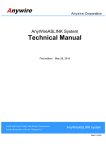
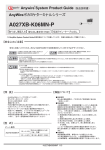
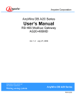
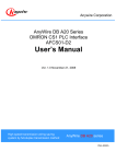
AnyWire System Products Guide
AnyWire Address Writer
ARW-03
Infrared non-contact type
Remote head wearable
AnyWire is a registered trademark of Anywire Corporation.
The Products Guide describes individual products. Refer to the Guide as necessary.
Category
Type
The version is
displayed when
POWER is on.
Firmware Version
Ver. 1.00 or lower Ver. 2.10 or higher
Adaptable
Equipment
POKAYOKETERMINAL
Dust-proof, small-sized,
door type
AnyWire ASLINK TERMINAL
All models
○
×
○
○
○: available, ×: unavailable
[Notes on Safety]
A “Ver. *.*.*” is
described on
this label.
Front
READER/WRITER
ARW-03 Ver.2.10
LotNo.***
MADE IN JAPAN
Back
Precautions that must be observed in order to use this system safely are indicated as shown below.
You must observe these precautions.
WARNING
WARNING
CAUTION
A WARNING indicates a potentially hazardous
situation which, if not handled correctly, could
result in death or serious injury.
CAUTION
A CAUTION indicates a potentially hazardous situation
which, if not handled correctly, may result in personal
injury or property damage.
○ System Safety
This system is intended for general industrial applications. It does not have functions for supporting applications requiring higher
levels of safety such as safety-related devices or accident prevention systems. The product must not be used for these purposes.
○ Always turn off the power before attempting to mount or replace.
○ For change of setting in the direct mode, values are updated to the changed values when they are written. Please note that direct
changes of addresses and others may result in unexpected operation.
○ System power supply
Use a stable, 24V DC power supply. Use of an unstable power supply may cause problems with the system.
○ Separately route high-voltage and power cables
Although the AnyWire System has a high noise margin, keep the transmission line and I/O cables away from high-voltage and
power cables.
○ Connectors and terminals
* Pay careful attention to the length and installation of cable wiring to ensure that connectors and cables are neither overloaded nor disconnected.
* Make sure to prevent any metal objects from getting inside the connectors or the terminal blocks.
* Short-circuits caused by metal objects or mis-wiring are likely to damage the device.
○ Do not impose any external loads on the units. Doing so may cause a failure.
○ Do not disconnect or reconnect between the transmission line and slave units. A malfunction may occur.
○ Use the AnyWire System within the range of the specifications and conditions shown below.
[Warranty]
[Features]
-This is a unit of the AnyWire system. It is used for setting addresses and operating specifications of units with an infrared writing port.
This writer enables addresses and parameters to be set by the non-contact
method.
- Writing and reading can be performed.
- As the body is small-sized and driven by battery, it has no power code and
can be taken anywhere.
- As address values are displayed at a 7-segment display unit and can be used
directly at the decimal scale, this eliminates inconveniences that it is hard to
see the switch in a dark place and the set value must be calculated.
- A remote head (ARW-RH) to make writing in a narrow space or small-sized
unit easier is prepared (separately sold).
- The writer has an automatic shutout function to protect the battery even when
the power is left on. (The condition in the middle of the setting operation
returns to the content before setting.)
[Type]
ARW-03
Infrared non-contact address writer (Ver. 2.10)
ARW-RH
Remote head for narrow space and small part
(sold separately)
Also available is a set of ARW-03 and ARW-RH.
Model: ARW-03-RH
■ Warranty period
The warranty on the delivered Product shall continue to be effective for
one (1) year after the delivery thereof to a location as designated by the
original owner.
■ Scope of warranty
Should a defect occur in any part of the Product during the foregoing
warranty period when it is used normally in acordance with the specifications described in this User's Manual, the Company shall replace or
repair the defect free of charge, except when it arises as a result of:
[1] Misuse or abuse of the Product by the owner;
[2] Fault caused by other than the delivered Product;
[3] The unauthorized modification or repair of the Product by any person
other than the Company's personnel;
[4] Any unusual force of nature, disaster or other cause beyond the Company's control.
The term "warranty," as used herein, refers to the warranty applicable to
the delivered product alone. The Company shall not be liable for consequential or incidental damages resulting from any malfunction.
■ Repair at cost
After the expiration of the warranty period, the owner shall be responsible for all costs and expenses incurred for the troubleshooting and
repair of the Product. Even during the warranty term, the Company shall
repair any defects arising from causes other than within the scope of the
warranty as specified above, at the owner's cost.
-ARW03 1/17-
[Overview]
ARW-03 can write addresses in a unit and read the addresses written in a terminal using infrared ray.
As the infrared ray emitting and receiving part is less influenced by ambient light, the writer can be used almost
anywhere indoors.
And the writer works well only by visual adjustment of the address writer optical axis at the time of transmission and
reception by the diffusion-type light emitting and receiving system with weak-directivity.
■Image of address writing
■Image of operation
Address setting port
on the terminal side
Address setting port
Infrared ray
Light emitting
and receiving part
The infrared ray irradiation direction and
position of ARW-03 are not strictly specified.
■Image of address reading
When the light emitting and receiving
part of ARW-03 and the address
setting port of a unit to be set are in
strong ambient light such as direct sunlight, it may be
impossible to write and read addresses.
In such cases, please shade the light by your hands, etc.
Address setting port
on the terminal side
CAUTION
Infrared ray
Light emitting
and receiving part
■Image with a remote head connected
POWER
Remote head for narrow space/small part
(ARW-RH)
It is convenient to connect a remote head for a narrow space difficult to
move close to the body of ARW-03 or for a small-sized terminal and
small infrared port.
For ARW-RH, refer to ARW-RH instruction manual.
-ARW03 2/17-
[Position during operation]
Operation is based on the assumption of operation within a range of some distance. The guideline for light emitting
and receiving distance is as follows:
■Guideline for positions in writing and reading addresses
Address setting port
Light emitting
and receiving part
Light emitting
and receiving part
Up to approximately 50mm Note)
Approximately 60°
Approximately 60°
Address setting port
[Seen from the top]
[Seen from the side]
Note) The distance from the terminal varies depending on
the terminal size.
In the case of a small terminal, it is necessary to
move the writer close to the terminal.
The vertical directions are not specified
for the front of ARW-03.
[Front]
-ARW03 3/17-
[Name of each part]
Light emitting and receiving part (in yellow)
Operating mode indicator lamp
POWER indicator lamp
Ring for strap
Comment display
RH connection connector
(for remote head connection)
POWER switch
SELECT switch
CLEAR switch
SET switch
UP/DOWN buttons
-ARW03 4/17-
[Type of operation]
The following operations are available for the ARW-03.
Purposes
Version
Measures
Mode to be selected
Ver.1.00
or lower
Ver. 2.10
or higher
Explanation
page
ARW-03 Initial check
Press the POWER
switch pressing
the SELECT switch.
Select the maximum
number of parameters
○
○
6
Teaching
Direct renewal
EX mode
×
○
7
Address reading
Direct reading
READ mode
○
○
8
Power reset renewal
WRITE mode
○
○
10
Direct renewal
DIRECT WRITE mode
○
○
11
Direct reading
READ mode
△
○
13
Power reset renewal
WRITE mode
△
○
14
Direct renewal
DIRECT WRITE mode
△
○
15
Address writing
Parameter reading
Parameter writing
Select the maximum address
○: available, △: conditioned, ×: unavailable
-ARW03 5/17-
[Precautions for use]
It is necessary to check the internal setting of the ARW-03 depending on the reading/writing unit.
Check the content of the setting memorized in this unit to match it with the target unit before use.
The following operations are necessary for correct setting in the target unit.
When using the address writer the first time, make sure to conduct the operations and check the content set in the writer.
If the matching of the address writer and unit is not correct and reading and writing operations are performed, it may cause the unit to
incorrectly operate. (If the setting is correctly adjusted again, that is not a problem.)
CAUTION
■Contents to be checked
The contents to be checked are the “maximum number of parameters to be selected” and “maximum points setting mode.”
“Maximum number of parameters to be selected” is the number of parameters that can be set and is registered within
the range of “1 – 6.”
For “maximum points setting mode,” the maximum of address “256” or “512” that can be set is switched according to
the type of unit.
●Maximum points setting mode
Terminal connection
targets
●Maximum number of parameters to be selected
Use mode
256 mode
512 mode
Open Terminal Series
Bitty Brdge
EZwire
POKAYOKETERMINAL
○
ー
A20 Series Master
ー
○
The maximum number of parameters is expressed as “Pn” and any number of 0 19 can be selected.
For example, if the maximum number is set to “4,” 4 types (01 – 04) can be
selected in the parameter mode.
This parameter is selected based on the setting target unit and its necessary
setting function.
Normally, set the number to “19 (maximum).”
However, the parameters to be used vary depending on the slave unit.
Set only the parameter number to be used.
If unnecessary parameters are written, it may result in a malfunction.
CAUTION
■Setting operation
How to operate
Display
1
Turn ON the POWER switch
pressing SELECT switch.
or
2
Press the UP switch once.
~
Any number from 0 to 19
is displayed.
3
Press the SET switch.
~
Dot flashing movement
4
Display the number to be set
by the UP/DOWN switches
to press the SET switch.
After “SEt” is displayed,
the set value is
displayed again.
Example)
In the case of setting
the maximum number of
parameters to 19
5
Press the L switch.
6
Press the DOWN switch once.
or
The display returns to that
of Operation No.1.
7
Press the SET switch.
or
Dot flashing movement
8
Display the number to be set
by the UP/DOWN switches
to press the SET switch.
9
Turn OFF the POWER switch.
Dot flashing movement
After “SEt” is displayed,
the set value is
displayed again.
In the case of setting the maximum
address to 256
In the case of setting the maximum
address to 512
If moving to the address setting etc., turn ON the POWER switch again.
-ARW03 6/17-
[EX Mode]
If using ASLINKAMP and ASLINKSENSOR, it is necessary to register the initial setting of ON/OFF operations with
respect to these terminals before using them.
It is “EX Mode” to perform this setting.
Make sure to perform ON/OFF setting.
! CAUTION If not, it may result in abnormal operation.
■Setting operation
How to operate
Display
1
Turn ON the POWER switch.
After approximately
2 seconds,
“SELECt” flashes.
2
Press the SELECT switch.
----Flashing
3
Press the SELECT switch
several times to light the EX display.
4
Press the SET switch.
SEt on mode
5
Set SEton in the condition where
the appropriate terminal detects a work.
During the setting
operation
6
When SEton setting is correctly set,
“Good” is displayed and then
“Seton” is displayed again.
Correctly completed
EX (red)
Setting is completed
7
If SEton setting is not correctly set,
“SEt Err” is displayed.
Readjust the light emitting and
receiving part to press the SET switch
again until Operation No.6 is completed.
Err display
8
After SEton setting is completed,
press the UP or DOWN switch once.
SEt oFF mode
9
And then remove the work from
the appropriate terminal to set SEtoFF.
During the setting
operation
When SEtoFF setting is correctly set,
Correctly completed
“SEtoFF” is displayed again.
Setting is completed
If SEton setting is not correctly set,
“SEt Err” is displayed.
Readjust the light emitting and
receiving part to press the SET switch
again until Operation No.8 is completed.
Err display
10 “Good” is displayed and then
11
12
13
To clear “Err” once,
press the CLEAR switch.
If moving to the next setting,
press the SELECT switch.
READ (green)
WRITE (yellow)
DIRECT WRITE (orange)
After using ARW-03, keep the POWER switch
pressed to turn OFF the power.
-ARW03 7/17-
EX must be lighted
Light emitting and
receiving part (yellow frame)
[Address reading…READ Mode]
This is the mode to read the addresses written in a unit.
Check that power (in the case of 2-wire type, transmission signal) is supplied to the reading target unit.
■Address reading operation
How to operate
Display
1
Turn ON the POWER switch.
After approximately
2 seconds,
“SELECt” flashes.
2
Press the SELECT switch.
----Flashing
3
Press the SELECT switch
several times to
light the READ display.
4
Press the SET switch.
5
Point the light emitting and
receiving part (yellow frame)
at the address setting port of
the unit to be written and
then press the SET switch.
6
The reading mode is
determined.
During the reading
operation
Example)
When moving to the next unit
to read addresses,
directly move to the next
address setting port to press
the SET switch and repeat reading.
7
In the case of failure in reading
8
Readjust the light emitting and
receiving part and
press the SET switch again.
9
READ (green)
Address values read
During the reading
operation
Example)
Address values read
Err display
During the reading
operation
Example)
- Clear the Err display.
- Switch the mode to another mode.
Address values read
Return to the reading
mode display
Press the CLEAR switch.
10
Press the SELECT switch
several times to light the display of
a desired mode.
11
Press the SET switch.
READ (green)
WRITE (yellow)
DIRECT WRITE (orange)
After using ARW-03, keep the POWER switch
pressed to turn OFF the power.
-ARW03 8/17-
READ must be lighted.
Light emitting and
receiving part (yellow frame)
[Writing of addresses…Notes]
There are two writing modes as follows. Understand it to select the mode.
Mode
WRITE
Details
When the power of the terminal and transmission
signals are turned off after the writing operation and
turned on again, the written values become available.
In consideration of safety of the system, writing in
this mode is recommended normally.
The written values become available at the time when
addresses are written.
DIRECT WRITE
As addresses can be updated with the power on, this is
an easy method. However, it requires careful attention
to operation so that unexpected terminal movement
may not cause an accident.
If using a branching/disconnection function, set all the addresses and then register the connection ID on the
master side by performing “automatic address recognition operation.”
If “automatic address recognition operation” is performed on the master side, when connection ID is registered to
change an address, it will cause a disconnection error.
In this case, perform “automatic address recognition operation” and then register the connection ID again.
DIRECT WRITE
WRITE
-ARW03 9/17-
Light emitting and receiving part
(yellow frame)
[Writing of addresses…WRITE Mode]
This is the mode to enable renewal by turning on the transmission signals and power again.
Check that power (in the case of 2-wire type, transmission signal) is supplied to the target unit in writing addresses.
And after writing all the addresses, confirm the safety and reset the power (in the case of 2-wire type, transmission
signal) of the target unit to update the result of writing.
■Address writing operation
How to operate
Display
1
Turn ON the POWER switch.
After approximately
2 seconds, “SELECt” flashes.
2
Press the SELECT switch.
Flashing
3
Press the SELECT switch several
times to light the WRITE display.
4
Press the SET switch.
The writing mode is
determined.
5
Press the SET switch.
Dot flashing movement
WRITE (yellow)
Display the address value to be written by
using the UP/DOWN switches.
6
If the R switch is operated, 50 addresses are
added. And if the number of addresses
added exceeds the maximum number of 250
or 500 (initial setting), it returns to 0 (zero).
7
Point the light emitting and receiving
part (yellow frame) at the address
setting port of the unit to be written
and then press the SET switch.
8
If moving to the next terminal to write
addresses, change the value by using
the UP/DOWN switches and repeat
writing operation with the SET switch.
Example)
Display the set
address values
During the writing operation
Example)
Written address values
During the writing operation
Example)
Written address values
9
In the case of failure in writing
Err display
10
Readjust the light emitting and
receiving part and
press the SET switch again.
During the writing operation
11
Example)
- Clear the Err display.
- Switch the mode to another mode.
Return to the WRITE mode
display.
Press the CLEAR switch.
12
Press the L switch.
13
Press the SELECT switch
several times to light the display of
a desired mode.
14
Press the SET switch.
15
Return to Operation No.6
for rewriting operation.
Written address values
Dot flashing movement
READ (green)
WRITE (yellow)
DIRECT WRITE (orange)
Dot flashing movement
After using ARW-03, keep the POWER switch pressed to turn OFF the power.
-ARW03 10/17-
[Direct writing of addresses…DIRECT WRITE Mode]
The values become available at the time when addresses are written.
Check that power (in the case of 2-wire type, transmission signal) is supplied to the target unit in writing addresses.
In this mode, the values are updated at the time when addresses are written. Please carry out the operation
carefully because the address response changes and it may result in unexpected movement.
■Address writing operation
How to operate
Display
1
Turn ON the POWER switch.
After approximately
2 seconds, “SELECt” flashes.
2
Press the SELECT switch.
Flashing
3
Press the SELECT switch several
times to light the DIRECT WRITE display.
4
Press the SET switch.
The writing mode is
determined.
5
Press the SET switch.
Dot flashing movement
Display the address value to be written by
using the UP/DOWN switches.
6
If the R switch is operated, 50 addresses are
added. And if the number of addresses
added exceeds the maximum number of 250
or 500 (initial setting), it returns to 0 (zero).
7
Point the light emitting and receiving
part (yellow frame) at the address
setting port of the unit to be written
and then press the SET switch.
8
If moving to the next terminal to write
addresses, change the value by using
the UP/DOWN switches and repeat
writing operation with the SET switch.
DIRECT WRITE (yellow)
Example)
Display the set
address values
During the writing operation
Example)
Written address values
During the writing operation
Example)
Written address values
9
In the case of failure in writing
Err display
10
Readjust the light emitting and
receiving part and
press the SET switch again.
During the writing operation
11
Example)
- Clear the Err display.
- Switch the mode to another mode.
Return to the WRITE mode
display.
Press the CLEAR switch.
12
Press the L switch.
13
Press the SELECT switch
several times to light the display of
a desired mode.
14
Press the SET switch.
15
Return to Operation No.6
for rewriting operation.
Written address values
Dot flashing movement
READ (green)
WRITE (yellow)
DIRECT WRITE (orange)
Dot flashing movement
After using ARW-03, keep the POWER switch pressed to turn OFF the power.
-ARW03 11/17-
[Parameters]
Parameter consists of the movement element and the
variable built in a unit.
For a type of unit to select parameters, select and set the
movement specification in ARW-03.
The following parameters are available depending on models.
Do not operate the writer with a value that
exceeds the following parameters or
variable values. This may cause the writer to malfunction.
If you try to set a value that exceeds the parameters and
variable values, “E-303” is displayed in the display portion
of ARW-03.
!
■Parameters of representative models
Type
Door type
fall-proof
Model
A027XB-F02□-P
A227XB-F02□-P
Details of parameter
01
1, 2, 3, 4, 5, 6, 7
Door upper position
02
1, 2, 3, 4, 5, 6, 7
Door lower position
03
1, 2, 3, 4, 5, 6, 7, 8, 9, 10
Timer
04
0 (green), 1 (red), 2 (blue), 3 (yellow), 4 (sky-blue),
5 (purple) and 6 (white) *7 or more cannot be set.
Display colors
05
06
01
Small-sized
fall-proof
ASLINKER
A027XB-K02VN-P
A027XB-K02V-P
A227XB-K02VN-P
A227XB-K02V-P
-
Reserve
-
Reserve
0 (green), 1 (red), 2 (blue), 3 (yellow), 4 (sky-blue),
5 (purple) and 6 (white) *7 or more cannot be set.
02
03
04
05
06
Display colors
-
-
Reserve
-
Reserve
-
Reserve
-
Reserve
Reserve
B280SB-02U□-C1220
B280PB-02U□-C1220
01
0 (I/O disconnection, 24VL short-circuit detection: OFF)
1 (I/O disconnection, 24VL short-circuit detection: ON)
Function
Selection
B281□B-02U□-CC20
01
0 (I/O disconnection, 24VL short-circuit detection: OFF)
1 (I/O disconnection, 24VL short-circuit detection: ON)
Function
Selection
01
Setting of sensor sensitivity (threshold)
Adjustment range: 0 – 100 (Before shipment: 50)
Function
Selection
02
Hysteresis setting for sensor sensitivity
Adjustment range: 0 – 100 (Before shipment: 5)
Function
Selection
03
Setting of upper limit of alarm judgment value
Adjustment range: 0 – 100 (Before shipment: 80)
Function
Selection
04
Setting of lower limit of alarm judgment value
Adjustment range: 0 – 100 (Before shipment: 20)
Function
Selection
05
Setting of monitoring time in alarm judgment value Function
Adjustment range: 3 – 255 (Before shipment: 50) (Unit: 0.1 sec) Selection
B289SB-01AF-CAM20
ASLINKAMP
CAUTION
B289SB-01AF-CAS
B289SB-01AP-CAM20
Switching of Dark ON and Light ON, Before shipment: 0
B289SB-01AP-CAS
06
Transmissiontype
Dark (shielding) ON: 0
Light (Transmission) ON: 1
Reflectiontype
Dark (without reflection) ON: 0
Light (with reflection) ON: 1
Setting of operating mode
07
08
0 (Diagnosis function: OFF)
1 (Diagnosis function: ON)
Function
Selection
*ASLINKAMP-side display interlock
Internal setting for photoelectric head
Variable: 0-3, Before shipment: 0
*This value is used for setting before shipment.
If changing this value, consult our Sales Division.
For details of the parameter, also refer to the instruction manual of each unit.
-ARW03 12/17-
Function
Selection
Function
Selection
[Parameters (sequel)]
■Parameters of representative models
Type
Model
Details of parameter
01
AnyWireASLINK
Mapping terminal
B232SB-MX100-STP 02
B232SB-SX100-STP
03
0, 1, 3, 4, 5, 6, 7, 8, 9, 10, 11, 12, 13, 14, 15
Before shipment: 10
Sensitivity
0 (Collective setting of sensitivity), 1 (Individual setting of sensitivity)
Before shipment: 0
Sensitivity setting mode
of B232SB-SX100-STP
0 (with error sensor unit monitoring function)
1 (without error sensor unit monitoring function)
Error sensor unit
monitoring
function
Before shipment: 0
[Reading of parameters]
Check that power (in the case of 2-wire type, transmission signal) is supplied to the reading target unit.
■Parameter reading operation
How to operate
Display
1
Turn ON the POWER switch.
After approximately
2 seconds, “SELECt” flashes.
2
Press the SELECT switch.
Flashing
3
Press the SELECT switch several
times to light the READ display.
4
Press the SET switch.
5
Press the UP switch to display
the P number of the parameter type
to be read from the target terminal.
6
Point the light emitting and
receiving part (Yellow frame) at
the unit to press the SET switch.
7
In the case of failure in reading
Err display
8
Readjust the light emitting and
receiving part and
press the SET switch again.
During the reading operation
9
READ (green)
The reading mode is
determined.
Example)
Select parameter 1.
During the reading operation
Example)
Example)
- Clear the Err display.
- Switch the mode to another mode.
Parameter value read
Parameter value read
Return to the reading
mode display
Press the CLEAR switch.
10
If reading parameters from
another unit, return to Operation No.6
to repeat the operations.
11
If returning to the address setting mode,
press the DOWN switch once.
Change to the Ad display.
After using ARW-03, keep the POWER switch
pressed to turn OFF the power.
-ARW03 13/17-
READ must be lighted.
Light emitting and
receiving part
(yellow frame)
[Writing of parameters]
This is the mode to enable renewal by turning on the transmission signals and power again.
Check that power (in the case of 2-wire type, transmission signal) is supplied to the target unit in writing addresses.
And after writing all the addresses, confirm the safety and reset the power (in the case of 2-wire type, transmission
signal) of the target unit to update the result of writing.
■Parameter writing operation
How to operate
Display
1
Turn ON the POWER switch.
After approximately
2 seconds, “SELECt” flashes.
2
Press the SELECT switch.
Flashing
3
Press the SELECT switch several
times to light the WRITE display.
4
Press the SET switch.
5
Press the UP switch once to change
the display to parameter writing.
6
Press the SET switch.
WRITE (yellow)
The writing mode is
determined.
Dot flashing movement
Display the parameter value to be
written by using the UP/DOWN switches.
Example)
Point the light emitting and receiving
part (yellow frame) at the address
setting port of the unit to be written
and then press the SET switch.
In the case of selecting
variable “1” in parameter 1
During the writing operation
Example)
Written parameter values
7
In the case of failure in writing
Err display
8
Readjust the light emitting and
receiving part and
press the SET switch again.
During the writing operation
9
If writing parameters from another
unit, return back to Operation
No.6 to repeat the operations.
10
Example)
- Clear the Err display.
- Switch the mode to another mode.
Written parameter values
Return to the writing
mode display
Press the CLEAR switch.
11
Press the L switch.
Dot flashing movement
12
If returning to the address setting mode,
press the DOWN switch once.
Change to the Ad display.
After using ARW-03, keep the POWER switch
pressed to turn OFF the power.
-ARW03 14/17-
WRITE must be lighted.
Light emitting and
receiving part
(yellow frame)
[Direct writing of parameters]
The values become available at the time when addresses are written.
Check that power (in the case of 2-wire type, transmission signal) is supplied to the target unit in writing addresses.
In this mode, the values are updated at the time when addresses are written. Please carry out the operation
carefully because the characteristics and movement change and it may result in unexpected operation.
■Parameter direct writing operation
How to operate
Display
1 Turn ON the POWER switch.
After approximately
2 seconds, “SELECt” flashes.
2 Press the SELECT switch.
Flashing
Press the SELECT switch several
3 times to light the DIRECT WRITE
display.
DIRECT WRITE (orange)
The writing mode is
determined.
4 Press the SET switch.
Press the UP switch once to change
5 the display to parameter writing.
Dot flashing movement
6 Press the SET switch.
Display the parameter value to be
written by using the UP/DOWN switches.
Example)
Point the light emitting and receiving
part (yellow frame) at the address
setting port of the unit to be written
and then press the SET switch.
In the case of selecting
variable “1” in parameter 1
During the writing operation
Example)
Written parameter values
Err display
7 In the case of failure in writing
Readjust the light emitting and
During the writing operation
8 receiving part and
press the SET switch again.
Example)
Written parameter values
If writing parameters from another
9 unit, return back to Operation
No.6 to repeat the operations.
- Clear the Err display.
10 - Switch the mode to another mode.
Return to the writing
mode display
Press the CLEAR switch.
11 Press the L switch.
Dot flashing movement
If returning to the address setting mode,
Change to the Ad display.
12 press the DOWN switch once.
After using ARW-03, keep the POWER switch
pressed to turn OFF the power.
-ARW03 15/17-
WRITE must be lighted.
Light emitting and
receiving part
(yellow frame)
[Battery replacement]
If the POWER indicator lamp flashes, the battery is almost dead. Please replace it with new one.
■Battery replacement
Condition
2
POWER switch OFF
POWER indicator lamp flashes
Batter is almost dead.
Battery replacement
POWER indicator lamp
Comment display
Power switch
Battery case
-
+
+
POWER switch ON
-
1
Display
2 AAA dry batteries
Battery case cover
Please pull the cover in the arrow direction.
CAUTION
Put batteries in the correct directions (+ and -). If not
put in the correct directions, it may cause a failure,
breakage, etc.
Properly dispose of used batteries in accordance with
the regulations of each local government.
*Dry batteries are separately packed to be attached to the writer.
The attached batteries are monitor batteries for operation check.
Therefore, the batteries may run down sooner than commercially
available batteries.
In such cases, purchase 2 “AAA dry batteries” separately.
Rechargeable batteries are not recommended.
-ARW03 16/17-
[Outer dimensions]
Unit: mm
100
61
19
[Address]
Anywire Corporation
Headquarters :1 Babazusho, Nagaokakyo-shi, Kyoto 617-8550 JAPAN
Contact
:Contact by mail
:Contact by website
[email protected]
http://www.anywire.jp
Printed in Japan 2011, 2013 UMA-08321F-EN
-ARW03 17/17-