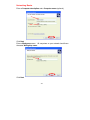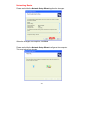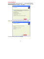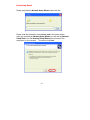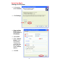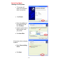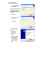
1
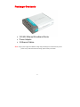
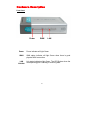
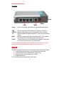
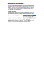
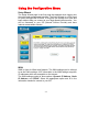
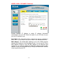
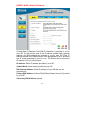
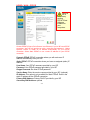
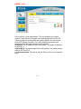
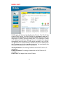
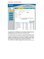
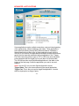
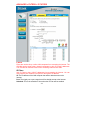
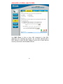
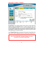
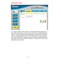
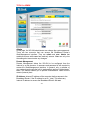
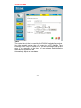
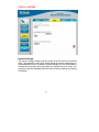
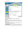
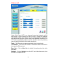
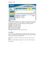
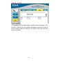
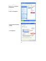
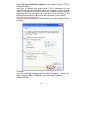
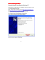
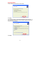
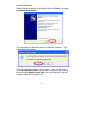
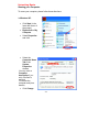
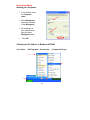
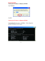
TM D-Link Express EtherNetwork VDI-604 4-Port Ethernet Broadband Router Manual Building Networks for People Contents Introduction.........................................................................................3 Package Contents .........................................................................7 Hardware Description..................................................................8 Reset ......................................................................................................9 Getting Started ...............................................................................10 Configuring the VDI-604 ..........................................................11 Using the Configuration Menu .............................................12 Troubleshooting.............................................................................41 Networking Basics .......................................................................47 Technical Specifications...........................................................77 Warranty .............................................................................................79 -2- Introduction The D-Link Express EtherNetwork VDI-604 is a 4-port Ethernet Broadband Router. The D-Link VDI-604 enables users to quickly and easily share a high speed Internet connection. The D-Link VDI-604 also incorporates many advanced features, traditionally found in more expensive routers. The VDI-604 is compatible with most popular operating systems, including Macintosh, Linux and Windows, and can be integrated into an existing network. This Manual is designed to help you connect the D-Link Express EtherNetwork VDI-604 to a high speed Internet connection and 4 Ethernet PC connections. This manual provides a quick introduction to Broadband Router Technology, Firewalls, and Local Area Networking. Please take a moment to read through this manual and get acquainted with these various technologies. Features and Benefits Ethernet Switch Allows you to quickly and easily share an Internet connection with multiple computers and devices. VPN supported Supports multiple and concurrent IPSec and PPTP pass-through sessions, so multiple users behind the VDI-604 can access corporate networks through various VPN clients more securely. Advanced Firewall & Parental Control Features The Web-Based user interface displays a number of advanced network management features including: Content Filtering Easily applied content filtering based on Mac Address, IP Address, URL and/or Domain Name. Filter Scheduling These filters can also be scheduled to be active on certain days or for a duration of hours or minutes. -3- Network Address Translation NAT allows you to share a single IP Address and protects you from outside intruders gaining access to your private network. DHCP Server Supported All of the networked computers can retrieve TCP/IP settings automatically from the VDI-604. Web-Based Management VDI-604 is configurable through any network computer’s web browser using Netscape or Internet Explorer. Access Control Supported Allows you to assign different access rights for different users. Virtual Server Supported Enables you to expose WWW, FTP and other services on your LAN to be accessible to Internet users. Special Application Supported Special applications requiring multiple connections, like Internet gaming, video conferencing, Internet telephony and so on. The VDI-604 can sense the application type and open a multi-port tunnel for it. DMZ Host Supported Allows a networked computer to be fully exposed to the Internet. This function is used when the Special Application feature is insufficient to allow an application to function correctly. -4- Technology Introduction Introduction to Broadband Router Technology A router is a device that forwards data packets from a source to a destination. Routers forward data packets using IP addresses and not a MAC address. A router will forward data from the Internet to a particular computer on your LAN. The information that makes up the Internet gets moved around using routers. When you click on a link on a web page, you send a request to a server to show you the next page. The information that is sent and received from your computer is moved from your computer to the server using routers. A router also determines the best route that your information should follow to ensure that the information is delivered properly. A router controls the amount of data that is sent through your network by eliminating information that should not be there. This provides security for the computers connected to your router, because computers from the outside cannot access or send information directly to any computer on your network. The router determines which computer the information should be forwarded to and sends it. If the information is not intended for any computer on your network, the data is discarded. This keeps any unwanted or harmful information from accessing or damaging your network. Introduction to Firewalls A firewall is a device that sits between your computer and the Internet that prevents unauthorized access to or from your network. A firewall can be a computer using firewall software or a special piece of hardware built specifically to act as a firewall. In most circumstances, a firewall is used to prevent unauthorized Internet users from accessing private networks or corporate LAN’s and Intranets. A firewall watches all of the information moving to and from your network and analyzes each piece of data. Each piece of data is checked against a set of criteria that the administrator configures. If any data does not meet the criteria, that data is blocked and discarded. If the data meets the criteria, the data is passed through. This method is called packet filtering. A firewall can also run specific security functions based on the type of application or type of port that is being used. For example, a firewall can be configured to work with an FTP or Telnet server. Or a firewall can be configured to work with specific UDP or TCP ports to allow certain applications or games to work properly over the Internet. -5- Introduction to Local Area Networking Local Area Networking (LAN) is the term used when connecting several computers together over a small area such as a building or group of buildings. LAN’s can be connected over large areas. A collection of LAN’s connected over a large area is called a Wide Area Network (WAN). A LAN consists of multiple computers connected to each other. There are many types of media that can connect computers together. The most common media is CAT5 cable (UTP or STP twisted pair wire.) On the other hand, wireless networks do not use wires; instead they communicate over radio waves. Each computer must have a Network Interface Card (NIC), which communicates the data between computers. A NIC is usually a 10Mbps network card, or 10/100Mbps network card, or a wireless network card. Most networks use hardware devices such as hubs or switches that each cable can be connected to in order to continue the connection between computers. A hub simply takes any data arriving through each port and forwards the data to all other ports. A switch is more sophisticated, in that a switch can determine the destination port for a specific piece of data. A switch minimizes network traffic overhead and speeds up the communication over a network. Networks take some time in order to plan and implement correctly. There are many ways to configure your network. You may want to take some time to determine the best network set-up for your needs. -6- Package Contents VDI-604 Ethernet Broadband Router Power Adapter 2 Ethernet Cables Note: Using a power supply with a different voltage rating will damage and void the warranty for this product. If any of the above items are missing, please contact your reseller. -7- Hardware Description Front Panel Power Power WAN LAN Power indicator will light Green. WAN WAN status indicator will light Green when there is good physical WAN connection. LAN Link/Act. Link status indicators light Green. The LED flickers when the corresponding port is sending or receiving data. -8- Hardware Description Rear Panel Reset WAN LAN Power Reset Used to restore the VDI-604 back to factory default settings. LAN PORTS* 1-4 LAN port sockets (CAT5 Ethernet RJ-45 cable). The LED glows steadily when a port is connected to a hub, switch or network-adapter-equipped computer in your local area network (LAN.) WAN port socket (CAT5 Ethernet RJ-45 cable). This is where you will connect to your high speed Internet access Connect one end of your included power adapter to the power port and the other end into your power outlet. WAN* Power *All ports (both LAN & WAN) are Auto-MDIX. All ports auto-sense cable types to accommodate Straight-through or Cross-over cable. Reset To reset the system settings to factory defaults, please follow these steps: 1. Leave the device powered on, do not disconnect the power 2. Press the reset button and hold (use a paper-clip) 3. Keep the button pressed about 10 seconds 4. Release the button The VDI-604 will then automatically reboot itself. -9- Getting Started Installation Location The VDI-604 can be positioned at any convenient place in your office or house. No special wiring or cooling requirements are needed. However, you should comply with the following guidelines: Place the VDI-604 on a flat horizontal plane. Keep away from any heating devices. Do not place in a dusty or wet environment. The recommended operational specifications of the VDI-604 are: 32o F Temperature ~ 131o F Humidity 5 % ~ 90 % In addition, remember to turn off the power, remove the power cord from the outlet, and keep your hands dry when you install the hardware. Network Settings To use the VDI-604 correctly, you have to properly configure the network settings of your computers. The default IP address of the VDI-604 is 192.168.0.1, and the default subnet mask is 255.255.255.0. These addresses can be changed as needed, but the default values are used in this manual. If the TCP/IP environment of your computer has not yet been configured, you can refer to Configuring Your PCs to Connect to the VDI-604 to configure it. For example: 1. Configure your computer IP as 192.168.0.3, subnet mask as 255.255.255.0 and gateway as 192.168.0.1 Or more conveniently 2. Configure your computers to obtain TCP/IP settings automatically from the DHCP server feature of the VDI-604 Since the IP address of the VDI-604 is 192.168.0.1, the IP address of your computer must be 192.168.0.X (where “X” is a number between 2 and 254.) Each computer on your network must have a different IP address within that range. The default gateway must be 192.168.0.1 (the IP address of the VDI-604). -10- Configuring the VDI-604 The VDI-604 provides an embedded Web-based management utility making it operating system independent. You can configure your VDI-604 through the Netscape Communicator or Internet Explorer browser in MS Windows, Macintosh, Linux or UNIX based platforms. All that is needed is a web browser such as Internet Explorer or Netscape Navigator version 4 and higher with Java Script enabled. Start-up and Log in Activate your web browser and type in the IP address of the VDI-604 into the Location (for Netscape) or Address (for IE) field and press “Enter.” The default IP address of the VDI-604 is 192.168.0.1 For example: http://192.168.0.1 After the connection is established, the logon screen will pop up. To log in as an administrator, enter the username of “admin” and the password of “password” . Click the OK button. If the password is correct, the web-management interface will appear. -11- Using the Configuration Menu Setup Wizard The Setup Wizard page is the first page that appears when logging into the web-based management interface. The Setup Wizard is a utility used to quickly configure the VDI-604. It will guide you through four quick and basic steps to help you connect to your Ihigh speed Internet access . You will be connected to your ISP (Internet Service Provider) and have Internet access within minutes. WAN WAN is short for Wide Area Network. The WAN settings can be referred to as the Public settings. All IP information in the WAN settings are public IP addresses which are accessible on the Internet. The WAN settings consist of three options: Dynamic IP Address, Static IP Address, and PPPoE. Select the appropriate option and fill in the information needed to connect to your ISP. -12- HOME > WAN > DYNAMIC IP Address Choose Dynamic IP Address to obtain IP address information automatically from your ISP. Select this option if your ISP does not give you any IP numbers to use. Host Name: The Host Name field is optional but may be required by some ISPs. The host name is the device name of the Broadband Router. MAC Address: The default MAC address is set to the WAN's physical interface MAC address on the Broadband Router. You can use the "Clone MAC Address" button to copy the MAC address of the Ethernet Card installed by your ISP and replace the WAN MAC address with this MAC address. It is not recommended that you change the default MAC address unless required by your ISP. -13- HOME > WAN > Static IP Address Choose Static IP Address if all WAN IP information is provided to you by your ISP. You will need to enter in the IP address, subnet mask, gateway address, and DNS address(es) provided to you by your ISP. Each IP address entered in the fields must be in the appropriate IP form, which are four IP octets separated by a dot (x.x.x.x). The Router will not accept the IP address if it is not in this format. IP Address: Public IP address provided by your ISP. Subnet Mask: Subnet mask provided by your ISP. ISP Gateway Address: Public IP address of your ISP that you are connecting to. Primary DNS Address: Primary DNS (Domain Name Server) IP provided by your ISP Secondary DNS Address: optional -14- HOME > WAN > PPPOE Please be sure sure to remove any existing PPPoE Client Software installed on your computers. 1492 Choose PPPoE (Point to Point Protocol over Ethernet) if you’re ISP uses PPPoE connection. Your ISP will provide you with a username and password. . Select Dynamic PPPoE to obtain an IP address automatically for your PPPoE connection. Select Static PPPoE to use a static IP address for your PPPoE connection. Dynamic PPPoE: PPPoE connection where you will receive an IP address automatically from your ISP Static PPPoE: PPPoE connection where you have an assigned (static) IP address User Name: Your PPPoE username provided by your ISP Password: Your PPPoE password provided by your ISP Retype Password: Re-enter PPPoE password Service Name: Enter the service name provided by your ISP. (optional) IP Address: This option is only available for Static PPPoE. Enter in the static IP address for the PPPoE connection. Primary DNS Address: Primary DNS IP provided by your ISP Secondary DNS Address: optional -15- Maximum Idle Time: The amount of time of inactivity before disconnecting your PPPoE session. Enter a Maximum Idle Time (in minutes) to define a maximum period of time for which the Internet connection is maintained during inactivity. If the connection is inactive for longer than the defined Maximum Idle Time, then the connection will be dropped. Either set this to zero or enable Auto-reconnect to disable this feature. MTU: MTU stands for Maximum Transmission Unit. For PPPoE connections, you may need to change the MTU settings in order to work correctly with your ISP. Auto-Reconnect: If enabled, the Broadband Router will automatically connect to your ISP after your system is restarted or if the connection is dropped. -16- HOME > LAN LAN is short for Local Area Network. This is considered your internal network. These are the IP settings of the LAN interface for the VDI-604. These settings may be referred to as Private settings. You may change the LAN IP address if needed. The LAN IP address is private to your internal network and cannot be seen on the Internet. IP Address: The IP address of the LAN interface. The default IP address is 192.168.0.1. Subnet Mask: The subnet mask of the LAN interface. The default subnet mask is 255.255.255.0. Local Domain Name: This field is optional. Enter in the your local domain name. -17- HOME > DHCP DHCP stands for Dynamic Host Configuration Protocol. The VDI-604 has a built-in DHCP server. The DHCP Server will automatically assign an IP address to the computers on the LAN/private network. Be sure to set your computers to be DHCP clients by setting their TCP/IP settings to “Obtain an IP Address Automatically.” When you turn your computers on, they will automatically load the proper TCP/IP settings provided by the VDI-604. The DHCP Server will automatically allocate an unused IP address from the IP address pool to the requesting computer. You must specify the starting and ending address of the IP address pool. Starting IP Address: The starting IP address for the DHCP server’s IP assignment. Ending IP Address: The ending IP address for the DHCP server’s IP assignment. Lease Time: The length of time for the IP lease. -18- ADVANCED > VIRTUAL SERVER The VDI-604 can be configured as a virtual server so that remote users accessing Web or FTP services via the public IP address can be automatically redirected to local servers in the LAN network. The VDI-604 firewall feature filters out unrecognized packets to protect your LAN network so all computers networked with the VDI-604 are invisible to the outside world. If you wish, you can make some of the LAN computers accessible from the Internet by enabling Virtual Server. Depending on the requested service, the VDI-604 redirects the external service request to the appropriate server within the LAN network. The VDI-604 is also capable of port-redirection meaning incoming traffic -19- to a particular port may be redirected to a different port on the server computer. Each virtual service that is created will be listed at the bottom of the screen in the Virtual Servers List. There are already pre-defined virtual services already in the table. You may use them by enabling them and assigning the server IP to use that particular virtual service. Name: The name referencing the virtual service. Private IP: The server computer in the LAN network that will be providing the virtual services. Private Port: The port number of the service used by the Private IP computer. Protocol Type: The protocol used for the virtual service. Public Port: The port number on the WAN side that will be used to access the virtual service. Schedule: The schedule of time when the virtual service will be enabled. The schedule may be set to Always, which will allow the particular service to always be enabled. If it is set to Time, select the time frame for the service to be enabled. If the system time is outside of the scheduled time, the service will we disabled. Example #1: If you have a Web server that you wanted Internet users to access at all times, you would need to enable it. Web (HTTP) server is on LAN computer 192.168.0.25. HTTP uses port 80, TCP. Name: Web Server Private IP: 192.168.0.25 Protocol Type: TCP Private Port: 80 Public Port: 80 Schedule: always -20- Click on this icon to edit the virtual service. Click on this icon to delete the virtual service. Example #2: If you have an FTP server that you wanted Internet users to access by WAN port 2100 and only during the weekends, you would need to enable it as such. FTP server is on LAN computer 192.168.0.30. FTP uses port 21, TCP. Name: FTP Server Private IP: 192.168.0.30 Protocol Type: TCP Private Port: 21 Public Port: 2100 Schedule: From: 01:00AM to 01:00AM, Sat to Sun All Internet users who want to access this FTP Server must connect to it from port 2100. This is an example of port redirection and can be useful in cases where there are many of the same servers on the LAN network. -21- ADVANCED > APPLICATIONS Some applications require multiple connections, such as Internet gaming, video conferencing, Internet telephony and others. These applications have difficulties working through NAT (Network Address Translation). Special Applications makes some of these applications work with the VDI-604. If you need to run applications that require multiple connections, specify the port normally associated with an application in the "Trigger Port" field, select the protocol type as TCP or UDP, then enter the public ports associated with the trigger port to open them for inbound traffic. The VDI-604 provides some predefined applications in the table on the bottom of the web page. Select the application you want to use and enable it. Note! Only one PC can use each Special Application tunnel. Trigger Name: This is the name referencing the special application. Trigger Port: This is the port used to trigger the application. It can be either a single port or a range of ports. -22- Trigger Type: This is the protocol used to trigger the special application. Public Port: This is the port number on the WAN side that will be used to access the application. You may define a single port or a range of ports. You can use a comma to add multiple ports or a hyphen to add port ranges. Public Type: This is the protocol used for the special application. -23- ADVANCED > FILTERS > IP FILTERS Filters Filters are used to deny or allow LAN computers from accessing the Internet. The VDI-604 can be setup to deny internal computers by their IP or MAC addresses. The VDI-604 can also block users from accessing restricted web sites. IP Filters Use IP Filters to deny LAN IP addresses from accessing the Internet. You can deny specific port numbers or all ports for the specific IP address. IP: The IP address of the LAN computer that will be denied access to the Internet. Port: The single port or port range that will be denied access to the Internet. Schedule: This is the schedule of time when the IP Filter will be enabled. -24- ADVANCED > FILTERS > MAC FILTERS Use MAC Filters to allow or deny LAN computers by their MAC addresses from accessing the Internet. You can either manually add a MAC address or select the MAC address from the list of clients that are currently connected to the Broadband Router. -25- ADVANCED > FILTERS > URL BLOCKING URL Blocking is used to deny LAN computers from accessing specific web sites by its URL. A URL is a specially formatted text string that defines a location on the Internet. If any part of the URL contains the blocked word, the site will not be accessible and the web page will not display. -26- ADVANCED > FILTERS > DOMAIN BLOCKING Domain Blocking is used to allow or deny LAN computers from accessing specific domains on the Internet. Domain blocking will deny all requests to a specific domain such as http and ftp. It can also allow computers to access specific sites and deny all other sites. -27- ADVANCED > FILTERS > FIREWALL Firewall Rules is an advance feature used to deny or allow traffic from passing through the Broadband Router. It works in the same way as IP Filters with additional settings. You can create more detailed access rules for the VDI-604. When virtual services are created and enabled, it will also display in Firewall Rules. Firewall Rules contains all network firewall rules pertaining to IP (Internet Protocol). In the Firewall Rules List at the bottom of the screen, the priorities of the rules are from top (the highest priority) to the bottom (the lowest priority.) Note: The VDI-604 MAC Address filtering rules have precedence over the Firewall Rules. -28- ADVANCED > DMZ If you have a client PC that cannot run Internet applications properly from behind the VDI-604, then you can set the client up to unrestricted Internet access. It allows a computer to be exposed to the Internet. This feature is useful for gaming purposes. Enter the IP address of the internal computer that will be the DMZ host. Adding a client to the DMZ (Demilitarized Zone) may expose your local network to a variety of security risks, so only use this option as a last resort. -29- TOOLS > ADMIN Admin At this page, the VDI-604 administrator can change the system password. There are two accounts that can access the Broadband Router’s Web-Management interface. They are admin and user. Admin has read/write access while user has read-only access. User can only view the settings but cannot make any changes. Remote Management Remote Management allows the VDI-604 to be configured from the Internet by a web browser. A username and password is still required to access the Web-Management interface. In general, only a member of your network can browse the built-in web pages to perform “Administrator” tasks. This feature enables you to perform “Administrator” tasks from the remote (Internet) host. IP Address: Internet IP address of the computer that has access to the Broadband Router. If the IP address is set to * (star). This allows any Internet IP address to access the Broadband Router. It is not -30- recommended that you set the IP address to * (star), because this allows any Internet IP address to access the Broadband Router, which could result in a loss of security for your network. If you elect to enable Remote Management, enter the IP Address of your remote location. Port: The port number used to access the Broadband Router. (Select from the pull-down menu.) Example: http://x.x.x.x:8080 where x.x.x.x is the WAN IP address of the Broadband Router and 8080 is the port used for the Web-Management interface. -31- TOOLS > TIME Time The system time is the time used by the VDI-604 for scheduling services. You can manually set the time or connect to a NTP (Network Time Protocol) server. If an NTP server is set, you will only need to set the time zone. If you manually set the time, you may also set Daylight Saving dates and the system time will Automatically adjust on those dates. -32- TOOLS > SYSTEM System Settings The current system settings can be saved as a file onto the local hard drive. The saved file or any other saved setting file can be loaded back on the Broadband Router. To reload a system settings file, click on Browse to browse the local hard drive and locate the system file to be used. You may also reset the Broadband Router back to factory settings by clicking on Restore. -33- TOOLS > MISC Miscellaneous Items These are additional tools and features of the Broadband Router. Ping Test This useful diagnostic utility can be used to check if a computer is on the Internet. It sends ping packets and listens for replies from the specific host. Restart Device If for any reason the Broadband Router is not responding correctly, you may want to restart the Broadband Router. Block WAN Ping When you “Block WAN Ping”, you are causing the public WAN IP address on the Broadband Router to not respond to ping commands. Pinging -34- public WAN IP addresses is a common method used by hackers to test whether your WAN IP address is valid. Discard PING from WAN side: By enabling this option, the VDI-604 will not reply to ping (ICMP) request packets from the Internet. VPN Pass-Through The Broadband Router supports VPN (Virtual Private Network) pass-through for both PPTP (Point-to-Point Tunneling Protocol) and IPSec (IP Security). Once VPN pass-through is enabled, there is no need to open up virtual services. Multiple VPN connections can be made through the Broadband Router. This is useful when you have many VPN clients on the LAN network. -35- TOOLS > VCT Virtual Cable Tester (VCT) is an advanced feature that integrates a LAN cable tester on every Ethernet port on the router. Through the graphical user interface (GUI), VCT can be used to remotely diagnose and report cable faults such as opens, shorts, swaps, and impedance mismatch. The VCT feature significantly reduces service calls and returns by allowing users to easily troubleshoot their cable connections. Ports – The Ethernet port names associated to the physical ports. Link Status – The current link status of the Ethernet cable connected to the respective Ethernet port. More Info – Click on More Info for detailed information about the cable link status. Refresh – Click on Refresh to run the VCT test. Allow the router a few seconds to complete the test. -36- STATUS > DEVICE INFORMATION This page displays the current information for the Broadband Router. It will display the WAN, LAN, and MAC address information. If your WAN connection is set up for Dynamic IP address, there will be a Release button and Renew button. Use Release to disconnect from your ISP and use Renew to connect to your ISP. If your WAN connection is set up for PPPoE, there will be a Connect button and Disconnect button. Use Disconnect to drop the PPPoE connection and use Connect to establish the PPPoE connection. -37- This page allows you to observe the VDI-604’s working status: WAN • • • • • LAN • • IP Address: WAN/Public IP Address Subnet Mask: WAN/Public Subnet Mask Gateway: WAN/Public Gateway IP Address Domain Name Server: WAN/Public DNS IP Address Wan Status: WAN Connection Status IP Address: LAN/Private IP Address of the VDI-604 Subnet Mask: LAN/Private Subnet Mask of the VDI-604 Firmware version: Displays the current firmware version WAN MAC Address: Displays the WAN port MAC/hardware address LAN MAC Address: Displays the LAN port MAC/hardware address -38- STATUS > LOG Log The Broadband Router keeps a running log of events and activities occurring on the Router. If the device is rebooted, the logs are automatically cleared. You may save the log files under Log Setting. First Page - The first page of the log. Last Page - The last page of the log. Previous - Moves back one log page. Next - Moves forward one log page. Clear - Clears the logs completely. Log Settings - Brings up the page to configure the logs. Log Settings Not only does the Broadband Router display the logs of activities and events, it can be setup to send these logs to another location. The logs can be sent via email to an email account. SMTP Server - The address of the SMTP server that will be used to send the logs. Send to - The email address the logs will be sent to. Click on Email Log Now to send the email. -39- STATUS > STATS Traffic Statistics The Broadband Router keeps statistic of traffic that passes through it. You are able to view the amount of packets that passes through the Router on both the WAN port and the LAN port. The traffic counter will reset if the device is rebooted. -40- Troubleshooting If you do not wish to set the static IP address on your PC, you will need to configure your PC to request an IP address from the gateway. Click the Start button, select Settings, and select Control Panel. Double-click the Network icon. In the configuration tab, select the TCP/IP protocol line that has been associated with your network card/adapter. If there is no TCP/IP line listed, you will need to install TCP/IP now. Click the Properties button. Choose the IP ADDRESS tab. Select Obtain an IP automatically. -41- After clicking OK, windows might ask you to restart the PC. Click Yes. CONFIRM YOUR PC’S IP CONFIGURATION There are two tools which are great for finding out a computer’s IP configuration: MAC address and default gateway. WINIPCFG (for Windows 95/98) Inside the windows 95/98 Start button, select Run and type winipcfg. In the example below this computer has an IP address of 192.168.0.100 and the default gateway is 192.168.0.1. The default gateway should be the network device IP address. The MAC address in windows 95/98 is called the Adapter Address. NOTE: You can also type winipcfg in the DOS command prompt. -42- IPCONFIG (for Windows 2000/NT/XP) At the command prompt type IPCONFIG and press Enter. Your PC IP information will be displayed as shown below. -43- Assigning a Static IP Address Note: Residential Gateways/Broadband Routers will automatically assign IP Addresses to the computers on the network, using DHCP (Dynamic Host Configuration Protocol) technology. If you are using a DHCP-capable Gateway/Router you will not need to assign Static IP Addresses. If you are not using a DHCP capable Gateway/Router, or you need to assign a Static IP Address, please follow these instructions: Go to START Double-click on Control Panel Double-click on Network Connections -44- Right-click on Local Area Connections. Double-click Properties Highlight Internet Protocol (TCP/IP) Click Properties -45- Select Use the following IP address in the Internet Protocol (TCP/IP) Properties window. Input your IP address and subnet mask. (The IP Addresses on your network must be within the same range. For example, if one computer has an IP Address of 192.168.0.2, the other computers should have IP Addresses that are sequential, like 192.168.0.3 and 192.168.0.4. The subnet mask must be the same for all the computers on the network.) Input your DNS server addresses. The DNS server information will be provided by your ISP (Internet Service Provider.) 192. 168 . 0. 192. 168 . 0. Click OK You have completed the assignment of a Static IP Address. (You do not need to assign a Static IP Address if you have a DHCP-capable Gateway/Router.) -46- Networking Basics Using the Network Setup Wizard in Windows XP In this section you will learn how to establish a network at home or work, using Microsoft Windows XP. Note: Please refer to websites such as http://www.homenethelp.com and http://www.microsoft.com/windows2000 for information about networking computers using Windows 2000, ME or 98. Go to Start>Control Panel>Network Connections Select Set up a home or small office network When this screen appears, Click Next. -47- Networking Basics Please follow all the instructions in this window: Click Next In the following window, select the best description of your computer. If your computer connects to the Internet through a gateway/router, select the second option as shown. Click Next -48- Networking Basics Enter a Computer description and a Computer name (optional.) Click Next Enter a Workgroup name. All computers on your network should have the same Workgroup name. Click Next -49- Networking Basics Please wait while the Network Setup Wizard applies the changes. When the changes are complete, click Next. Please wait while the Network Setup Wizard configures the computer. This may take a few minutes. -50- Networking Basics In the window below, select the best option. In this example, Create a Network Setup Disk has been selected. You will run this disk on each of the computers on your network. Click Next. Insert a disk into the Floppy Disk Drive, in this case drive A. Format the disk if you wish, and click Next. -51- Networking Basics Please wait while the Network Setup Wizard copies the files. Please read the information under Here’s how in the screen below. After you complete the Network Setup Wizard you will use the Network Setup Disk to run the Network Setup Wizard once on each of the computers on your network. To continue click Next. -52- Networking Basics Please read the information on this screen, then click Finish to complete the Network Setup Wizard. The new settings will take effect when you restart the computer. Yes to restart the computer. Click You have completed configuring this computer. Next, you will need to run the Network Setup Disk on all the other computers on your network. After running the Network Setup Disk on all your computers, your new wireless network will be ready to use. -53- Networking Basics Naming your Computer To name your computer, please follow these directions: In Windows XP: • Click Start (in the lower left corner of the screen) • Right-click on My Computer • Select Properties and click • Select the Computer Name Tab in the System Properties window. You may enter a Computer description if you wish, this field is optional. To rename the computer and join a domain, • Click Change -54- Networking Basics Naming your Computer • In this window, enter the Computer name. • Select Workgroup and enter the name of the Workgroup. • All computers on your network must have the same Workgroup name. • Click OK Checking the IP Address in Windows XP/2000 Go to Start > All Programs > Accessories -55- > Command Prompt Networking Basics Checking the IP Address in Windows XP/2000 Type Command Click OK Checking the IP Address in Windows XP/2000 Type ipconfig /all at the prompt. Click Enter. settings are displayed as shown below. All the configuration D-Link AirPlus DWL-650+ Wireless Cardbus Adapter -56- Networking Basics Checking the IP Address in Windows XP/2000 Type ipconfig /renew at the prompt to get a new IP Address. Enter. The new IP Address is shown below. Click (Windows 98/ME users: go to Start > Run. Type Command. Type winipcfg at the prompt. Click Release and Renew to obtain a new IP Address.) -57- Assigning a Static IP Address Note: Residential Gateways/Broadband Routers will automatically assign IP Addresses to the computers on the network, using DHCP (Dynamic Host Configuration Protocol) technology. If you are using a DHCP-capable Gateway/Router you will not need to assign Static IP Addresses. If you are not using a DHCP capable Gateway/Router, or you need to assign a Static IP Address, please follow these instructions: • Go to Start • Double-click on Control Panel -58- Networking Basics Assigning a Static IP Address • Double-click on Network Connections • Right-click on Local Area Connections. • Double-click Properties -59- Networking Basics Assigning a Static IP Address • • • Highlight Internet Protocol(TCP/IP) DWL-650+ Wireless Cardbus Adapter Click Properties Select Use the following IP address in the Internet Protocol (TCP/IP) Properties window (shown below.) • Input your IP address and subnet mask. (The IP Addresses on your network must be within the same range. For example, if one computer has an IP Address of 192.168.0.2, the other computers should have IP Addresses that are sequential, like 192.168.0.3 and 192.168.0.4. The subnet mask must be the same for all the computers on the network.) • Input your DNS server addresses. (Note: If you are entering a DNS server, you must enter the IP Address of the Default Gateway.) The DNS server information will be provided by your ISP (Internet Service Provider.) -60- Networking Basics Adding and Sharing Printers in Windows XP After you have run the Network Setup Wizard on all the computers in your network (please see the Network Setup Wizard section at the beginning of Networking Basics,) you can use the Add Printer Wizard to add or share a printer on your network. Whether you want to add a local printer (a printer connected directly to one computer,) share an LPR printer (a printer connected to a print server) or share a network printer (a printer connected to your network through a Gateway/Router,) use the Add Printer Wizard, you can find the directions below: First, make sure that you have run the Network Setup Wizard on all of the computers on your network. We will show you 3 ways to use the Add Printer Wizard 1. Adding a local printer 2. Sharing an network printer 3. Sharing an LPR printer Adding a local printer (A printer connected directly to a computer) A printer that is not shared on the network and is connected directly to one computer is called a local printer. If you do not need to share your printer on a network, follow these directions to add the printer to one computer. -61- Networking Basics Adding a local printer • Go to Start> Printers and Faxes • Click on Add a printer -62- Networking Basics Adding a local printer • Click Next • Select Local printer attached to this computer • (Deselect Automatically detect and install my Plug and Play printer if it has been selected.) • Click Next • Select Use the following port: • From the pull-down menu select the correct port for your printer (Most computers use the LPT1: port, as shown in the illustration.) • Click Next -63- Networking Basics Adding a local printer • Select and highlight the correct driver for your printer. • Click Next (If the correct driver is not displayed, insert the CD or floppy disk that came with your printer and click Have Disk.) • At this screen, you can change the name of the printer (optional.) • Select Yes, to print a test page. A successful printing will confirm that you have chosen the correct driver. • Click Next -64- Networking Basics Adding a local printer This screen gives you information about your printer. Click Finish When the test page has printed, Click OK -65- Networking Basics Adding a local printer • Go to Start> Printers and Faxes A successful installation will display the printer icon as shown at right. You have successfully added a local printer. -66- Sharing a network printer After you have run the Network Setup Wizard on all the computers on your network, you can run the Add Printer Wizard on all the computers on your network. Please follow these directions to use the Add Printer Wizard to share a printer on your network: • Go to Start> Printer and Faxes -67- Networking Basics Sharing a network printer • Click on Add a Printer • Click Next • Select Network Printer • Click Next -68- Networking Basics Sharing a network printer • Select Browse for a printer • Click Next • Select the printer you would like to share. • Click Next • Click Finish -69- Networking Basics Sharing a network printer To check for proper installation: • Go to Start> Printers and Faxes The printer icon will appear at right, indicating proper installation. You have completed adding the printer. To share this printer on your network: • Remember the printer name • Run the Add Printer Wizard on all the computers on your network. • Make sure you have already run the Network Setup Wizard on all the network computers. After you run the Add Printer Wizard on all the computers in the network, you can share the printer. -70- Networking Basics Sharing an LPR printer To share an LPR printer (using a print server,) you will need a Print Server such as the DP-101P+. Please make sure that you have run the Network Setup Wizard on all the computers on your network. To share an LPR printer, please follow these directions: • Go to Start> Printers and Faxes • Click on Add a Printer The screen to the right will display. • Click Next • Select Local printer… • Click Next -71- Networking Basics Sharing an LPR printer • Select Create a new port • From the pull-down menu, select Standard TCP/IP Port, as shown. • Click Next • Please read the instructions on this screen. • Click Next • Enter the Printer IP Address and the Port Name, as shown. • Click Next -72- Networking Basics Sharing an LPR printer • In this screen, select Custom. • Click Settings • Enter the Port Name and the Printer Name or IP Address. • Select LPR • Enter a Queue Name (if your Print-Server/ Gateway has more than one port, you will need a Queue name.) • Click OK -73- Networking Basics Sharing an LPR printer • This screen will show you information about your printer. • Click Finish • Select the printer you are adding from the list of Printers. • Insert the printer driver disk that came with your printer. • Click Have Disk If the printer driver is already installed, • Select Keep existing driver • Click Next -74- Networking Basics Sharing an LPR printer • You can rename your printer if you choose. It is optional. Please remember the name of your printer. You will need this information when you use the Add Printer Wizard on the other computers on your network. • Click Next • Select Yes, to print a test page. • Click Next This screen will display information about your printer. • Click Finish to complete the addition of the printer. • Please run the Add Printer Wizard on all the computers on your network in order to share the printer. Note: You must run the Network Setup Wizard on all the computers on your network before you run the -75Add Printer Wizard. Other Tasks For help with other tasks in home or small office networking, see Using the Shared Documents folder and Sharing files and folders in the Help and Support Center in Microsoft Windows XP. -76- Technical Specifications Standards • IEEE 802.3 10Base-T Ethernet • IEEE 802.3u 100Base-TX Fast Ethernet • IEEE 802.3 Nway Auto-Negotiation VPN Pass Through / Multi-Sessions • PPTP • L2TP • IPSec Device Management Web-Based – requires at least Microsoft Internet Explorer v5 or later, Netscape Navigator v4 or later, or other Java-enabled browsers. Media Access Control CMSA/CA with ACK LEDS • Power • WAN • Local Network – 10/100 Operating Temperature 32*F to 131*F (0*C to 55*C) Humidity 95% maximum (non-condensing) Power Input External power Supply DC 5V, 2.0A Safety & Emissions -77- • FCC • UL Dimensions • L = 5.6in (142mm) • W = 4.3in (109mm) • H = 1.2in (31mm) Weight 0.44 lbs (200g) -78- Warranty Warranty Statement Limited Warranty (USA Only) Subject to the terms and conditions set forth herein, GTE.Net LLC d/b/a Verizon Internet Solutions and Verizon Internet Services Inc. (collectively “Verizon Online”) provide this Limited Warranty for the products you are obtaining through Verizon Online (“Product(s)”). This Limited Warranty is provided only to the person or entity (“Customer”) that originally purchased the Product(s) from: •Verizon Online and for • Products purchased and delivered within the fifty states of the United States and the District of Columbia Limited Warranty: Verizon Online warrants that the hardware portion of the Product(s) will be free from material defects in workmanship and materials from the date of original retail purchase of the Product(s) through Verizon Online for the period of one year (“Warranty Period”), except as otherwise stated herein. Verizon Online’s sole obligation shall be to repair or replace the defective hardware during the Warranty Period at no charge to Customer or to refund the price at Verizon Online’s sole discretion. Such repair or replacement will be provided by Verizon Online. The replacement hardware provided by Verizon Online may not be new or have an identical make, model or part. Verizon Online may in its sole discretion replace the defective hardware (or any part thereof) with any reconditioned product that Verizon Online reasonably determines is substantially equivalent (or superior) in all material respects to defective hardware. Repaired or replacement hardware will be warranted for the remainder of the original Warranty Period from the -79- date of original purchase from Verizon Online. If a material defect is incapable of correction or if Verizon Online determines in its sole discretion that it is not practical to repair or replace the defective hardware, the price paid by Customer for the defective hardware will be refunded by Verizon Online upon return to Verizon Online of the defective hardware. All hardware (or part thereof) that is replaced by Verizon Online, or for which the purchase price is refunded, shall become the property of Verizon Online upon replacement or refund. Limited Software Warranty: Verizon Online passes on to Customer the warranty of the Licensor that the software portion of the Product (“Software”) will substantially conform to the Licensor’s then current functional specifications for the Software, as set forth in the applicable documentation, from the date of Customer’s purchase of the Software for a period of ninety (90) days (“Software Warranty”) DIRECTLY OR INDIRECTLY, TO THE LIMITED WARRANTY. Except as otherwise required by law, including New York laws relating to consumer transactions, any cause of action or claim Customer may have with respect to the Product must be commenced within one (1) year after the claim or cause of action arises or such claim or cause of action is barred. Some states do not allow exclusion or limitation of incidental or consequential damages or limitations on how long an implied warrant lasts, so the foregoing limitations and exclusions may not apply. This Limited Warranty provides specific legal rights and the product owner may also have other rights which vary from state to state. Copyright Statement: No part of this publication or document accompanying this Product may be reproduced in any form, by any means or used to make any derivative such as translation, transformation or adaptation without permission from Verizon Online, as stipulated by the United States Copyright Act of 1976. Contents are subject to change without prior notice. Copyright © 2004 by Verizon. All rights reserved. CE Mark Warning: This is a Class B product. In a domestic environment, this Product may cause radio interference, in which case the user may be required to take adequate measures. -80- FCC Statement: This Product has been tested and found to comply with the limits for a Class B digital device, pursuant to part 15 of the FCC Rules. These limits are designed to provide reasonable protection against harmful interference in a residential installation. This Product generates, uses and can radiate radio frequency energy and, if not installed and used in accordance with the instructions, may cause harmful interference to radio communication. However, there is no guarantee that interference will not occur in a particular installation. If this Product does cause harmful interference to radio or television reception, which can be determined by turning the Product off and on, the Customer is encouraged to try to correct the interference by one or more of the following measures: • Reorient or relocate the receiving antenna. • Increase the separation between the Product and receiver. • Connect the Product into an outlet on a circuit different from that to which the receiver is connected. • Consult Verizon Online or an experienced radio/TV technician for help. • Return Product shall be packaged and shipped to Verizon Teleproducts, 400 Brandywine Parkway, West Chester, PA 19380. The Customer is responsible for taking the package to a UPS Ground or a common carrier, selected by Verizon Online, with shipping charges prepaid. What Is Not Covered: This Limited Warranty provided by Verizon Online does not cover: Products, which in Verizon Online’s sole discretion, have been subjected to abuse, accident, alternation, modification, tampering, negligence, misuse, faulty installation, lack of reasonable care, repair of service in any way that is not contemplated in the documentation for the Product or if the model or serial number has been altered, tampered with, defaced or removed; Initial installation, installation and removal of the Product for repair and shipping cost; Operational adjustments covered in the operating manual for the Product and normal maintenance; Damage that occurs in shipment, due to an act of God, failures due to power surge and cosmetic damage; Any hardware, software, firmware or other products or services provided by anyone other than Verizon -81- Online; Products that have been purchased from other than Verizon Online; Repair by any party other than Verizon Online or as directed by Verizon Online will void this Limited Warranty. Limitation of Liability: TO THE MAXIMUM EXTENT PERMITTED BY LAW, VERIZON ONLINE IS NOT LIABLE UNDER ANY CONTRACT, NEGLIGENCE, STRICT LIABILITY OR OTHER LEGAL OR EQUITABLE THEORY FOR ANY LOSS OF USE OF THE PRODUCT, INCONVENIENCE OR DAMAGES OF ANY CHARACTER, WHETHER DIRECT, SPECIAL, INCIDENTAL OR CONSEQUENTIAL (INCLUDING, BUT NOT LIMITED TO, DAMAGES FOR LOSS OF GOODWILL, LOSS OF REVENUE OR PROFIT, WORK STOPPAGE, COMPUTER FAILURE OR MALFUNCTION, FAILURE OF OTHER EQUIPMENT OR COMPUTER PROGRAMS TO WHICH THE PRODUCT IS CONNECTED WITH, LOSS OF INFORMATION OR DATA CONTAINED IN, STORED ON OR INTEGRATED WITH ANY PRODUCT RETURNED TO VERIZON ONLINE FOR WARRANTY SERVICE) RESULTING FROM THE USE OF THE PRODUCT RELATING TO WARRANTY SERVICE, OR ARISING OUT OF ANY BREACH OF THIS LIMITED WARRANTY, EVEN IF VERIZON ONLINE HAS BEEN ADVISED OF THE POSSIBILITY OF SUCH DAMAGES. THE SOLE REMEDY FOR A BREACH OF THE FOREGOING LIMITED WARRANTY IS REPAIR, REPLACEMENT OR REFUND OF THE DEFECTIVE OR NON-CONFORMING PRODUCT. THE MAXIMUM LIABILITY OF VERIZON ONLINE UNDER THIS WARRANTY IS LIMITED TO THE PURCHASE PRICE OF THE PRODUCT COVERED BY THE WARRANTY. THE FOREGOING EXPRESS WRITTEN WARRANTIES AND REMEDIES ARE EXCLUSIVE AND ARE IN LIEU OF ANY OTHER WARRANTIES OR REMEDIES, EXPRESS, IMPLIED OR STATUTORY. Governing Law: This Limited Warranty shall be governed by the laws of the State of New York, without reference to its principles or conflicts of laws. CUSTOMER AND VERIZON ONLINE CONSENT TO THE EXCLUSIVE PERSONAL JURISDICTION OF AND VENUE IN A COURT LOCATED IN NEW YORK COUNTY, NEW YORK, FOR ANY SUITS OR CAUSES OF ACTION CONNECTED IN ANY WAY, Period”), provided that -82- the Software is properly installed on approved hardware and operated as contemplated in its documentation. Verizon Online further passes on to Customer the warranty of the Licensor that, during the Software Warranty Period, the magnetic media on which the Licensor delivers the Software will be free of physical defects. The Licensor’s sole obligation shall be to replace the non-conforming Software (or defective media) with software that substantially conforms to the Licensor’s functional specifications for the Software or to refund the purchase price for the Software at Verizon Online’s sole discretion. The replacement Software is provided only to the original Customer and is subject to the terms and conditions of the license granted by the Licensor for the Software. Software will be warranted for the Software Warranty Period set forth above from the date the replacement Software is returned to Customer. If a material non-conformance is incapable of correction, or if Verizon Online determines in its sole discretion that it is not practical to replace the non-conforming Software, the price paid by the Customer for the non-conforming Software will be refunded by Verizon Online; provided that the non-conforming Software (and all copies thereof) is returned to Verizon Online. The license granted respecting any Software for which a refund is given automatically terminates. Non-Applicability of Warranty: The Limited Warranty provided hereunder for hardware and software Product will not be applied to and does not cover any Product not purchased directly through and from Verizon Online. Submitting a Claim: Customer may return the Product to Verizon Online based on its return policy. In case the return policy period has expired and Product is within the Warranty Period, Customer shall submit a claim to Verizon Online as outlined below, provided that only Customer may submit a claim: • Customer must submit with the Product as part of the claim a written description of the hardware defect or Software non-conformance in sufficient detail to allow Verizon Online to confirm the same. • Customer must obtain a Return Authorization (“RA”) number from Verizon Online and, if requested, provide written proof of purchase of Product (such as a copy of the dated purchase invoice of the Product) before the warranty service is provided. -83- • Upon Customer’s request, Verizon Online will provide Customer with an RA and postage-paid package for the original Product under warranty. No Cash on Delivery (“COD”) returns are allowed. • After an RA number is issued, the defective Product must be packaged securely in the provided packing material, original or other suitable shipping package, to ensure that it will not be damaged in transit, and the RA number must be prominently marked on the outside of the package. All accessories and manuals must be included in the shipping package, such as the power cord and Ethernet cable. VDI-604 Rev. 032205 -84-