1
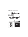
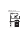
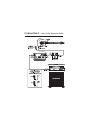
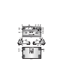
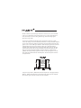
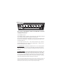
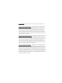
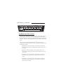
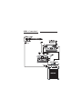
Your Cyborg™ Digital Delay pedal has been designed to comply with the
following Standards and Directives as set forth by the European Union:
Council Directive(s):
89/336/EEC
Electromagnetic Compatibility
Standard(s):
EN55013, EN50082-1
This means that this product has been designed to meet stringent guidelines on how much RF energy it can emit, and that it should be immune from
other sources of interference when properly used. Improper use of this
equipment could result in increased RF emissions, which may or may not
interfere with other electronic products.
To insure against this possibility, always use good shielded cables for all
audio input and output connections. This will help insure compliance with
the Directive(s).
For more information about other Rocktron products, please see your local
dealer or one of our importers closest to you (listed on the Rocktron website
- www.rocktron.com).
Precautions
Read all instructions contained in this manual.
Keep these instructions
Heed all warnings
Follow all instructions.
Do not use this apparatus near water.
Clean with dry cloth
Copyright © 2006 GHS Corporation
All Rights Reserved.
Precautions Continued....
Do not block any ventilation openings (if applicable). Install in accordance with the
manufacturer’s instructions.
Do not install near any heat sources such as radiators, heat registers, stoves or other
apparatus (including amplifiers) that produce heat.
This product is supplied with and runs on a 9VDC adapter.
Only used attachments/accessories specified by the manufacturer.
Do not use this product with any case, stand tripod, bracket or table that is not
specified by the manufacturer. Insure that the case, stand, tripod, bracket etc. is
properly adjusted and setup (follow all instructions). Extra care and caution should
be taken to avoid tip over and injury.
Unplug this apparatus during lightning storms or when unused during long periods
of time.
Refer all service to qualified service personnel. Servicing is required when the
apparatus has been damaged in any way, such as power supply or plug is damaged,
liquid has been spilled or objects have fallen into the apparatus or if the apparatus
has been exposed to rain or moisture, does not operate normally or has been
dropped.
DO NOT ATTEMPT TO SERVICE THIS EQUIPMENT. QUALIFIED PERSONNEL SHOULD SERVICE THIS EQUIPMENT ONLY. DO NOT MAKE ANY
INTERNAL ADJUSTMENTS OR ADDITIONS TO THIS EQUIPMENT AT ANY
TIME OR TAMPER WITH INTERNAL ELECTRONIC COMPONENTS AT ANY
TIME. FAILURE TO FOLLOW THESE INSTRUCTIONS MAY VOID THE
WARRANTY OF THIS EQUIPMENT AS WELL AS CAUSING A SHOCK
HAZARD.
OPERATING TEMPERATURE
Do not expose this unit to excessive heat. This unit is designed to operate between
32 F and 104 F (0 C and 40 C). This unit may not function properly under extreme
temperatures.
Introduction
Congratulations on your purchase of the Rocktron
Cyborg Digital Delay.
The Cyborg Digital Delay is one of a series of “Digital
Destiny” stomp boxes that break new ground in the
world of floor effects excellence. Simple to use, while
offering instant access effects, or satisfying those who
crave more complex control and the ability to create a
plethora of additional presets, the Cyborgs are low
noise, easy operation effects!
Rocktron has designed the Cyborg series around a
state-of-the-art Motorola® DSP engine. We’ve included
our HUSH® noise reduction technology, and provided
you with full bandwidth performance. We’ve cut no
corners in the design of these digital stomp boxes.
Cyborgs are fully MIDI programmable and controllable
and Cyborgs can be chained together and controlled by
a single Rocktron MIDI controller.
Look for other Cyborg Digital Destiny pedals at your
Rocktron retailer.
Connection 1 - Standard Connection
Connection 2 - Effects Loop
Connection 3 - with a Noisy Distortion Pedal
Descriptions
1
Preset Select Knob - this knob allows you to select the “preset” you desire.
Eight presets are available with this control. As the knob is turned the LED
under the selected preset will light.
2
LED Display - see following page for detailed descriptions of display.
3
Time Select Knob - this knob allows you to increase or decrease the delay
time of the preset.
4
Repeat Knob - this knob allows you to select the amount of times the delay
signal will “repeat” itself. As you turn the knob you will note that the LEDs
in the LED display will light in order from left to right as you increase the
amount of repeats. As you decrease the amount of repeats the LEDs will turn
off from right to left.
5
Level Knob - this knob determines the “volume” of the delay relative to the
dry signal. As you increase the delay volume the LEDs in the LED display
will light in order from left to right and stay lit. As you decrease the volume of
the delay the LEDs will turn off from right to left.
6
DC OnTap Power input. Use the supplied Rocktron DC OnTap adapter to
power your Cyborg pedal. Plug into a standard wall outlet and follow all
safety precautions.
7
Input Jack - plug your guitar into this jack. See preceeding pages for
standard connections.
8
HUSH Switch - The Cyborg Digital Delay pedal includes Rocktron Patented
Digital HUSH noise reduction. Select “ON” if the Delay pedal is placed after
a noisy distortion pedal. Select “OFF” when using clean tones. For more on
the HUSH and how it works, see the HUSH Section of this manual.
Descriptions Continued
9
Tap/Store Switch and Store LED - this switch allows you to set the delay
time by “tapping” the switch with your foot and to STORE changes to the
preset.
TAP function - Each of the 8 presets have a different tap parameter as
indicated on the top line of the LED Display (see point 2). The Tap
parameter is set (or fixed) for each preset and is not changeable. Simply
press the TAP button 4 consecutive times at the tempo you want . The
delay will automatically be quantized to one of the selected preset TAP
Button Parameters as shown below. The blue LED will flash to indicate the
quantized delay rate.
The resulting delay time can be:
One-half of the time between taps (8th Note)
Two-thirds of the time between taps (Triplet)
Equal to the time between taps (1/4 Note)
Two times the amount of time between taps (1/2 note)
Four times the amount of time between taps (Whole Note)
STORE function - Use this function to STORE (or save) changes you have
made to a preset. To operate the STORE function, press and hold the TAP/
STORE switch down for 2 seconds. This will save the changes to your
preset. The TAP/STORE LED will “hold on” and then return to flashing to
confirm the storgin process has been completed.
10
On/Off Footswitch and LED - this footswitch is used to turn “ON” or
“OFF” the Cyborg Delay. When the LED is lit , the delay is “ON”
11
Output Jack - Using a standard guitar cable with a 1/4” jack, plug into
your amplifier or the next effect pedal in your signal chain.
12
MIDI Jack - Using the Rocktron MIDI Breakout Cable (sold separately)
you can connect the Cyborg Pedal to a Rocktron MIDI Footcontroller such
as the Rocktron MIDI XChange, MIDI Mate or All Access. This feature
allows you to access all 64 presets and even connect other Cyborg pedals to
be controlled by the MIDI footcontroller.
HUSH® is Rocktron's patented single-ended noise reduction system, and is available
in all presets. The HUSH system provided in the Cyborg is a fully digital implementation, modeled after the latest analog HUSH design, achieved through Digital
Signal Processing (DSP).
The low level expander of the HUSH system operates like an electronic volume
control. The analog version of the HUSH system utilizes a voltage-controlled amplifier
(VCA) circuit which can control the gain between the input and the output from unity
gain to 30, 40 or even 50dB of gain reduction. When the input signal is above the userset threshold point, the VCA circuit remains at unity gain. (This means that the
amplitude of the output signal will be equal to that of the input signal.) As the input
signal level drops below the user preset threshold point, downward expansion will
begin. It is at this point that the expander acts like an electronic volume control,
gradually decreasing the output signal level relative to the input signal level. As the
input signal drops further below the threshold point, downward expansion increases
(see figure below).
A drop in the input level by 20dB would cause the output level to drop approximately
40dB (i.e., 20dB of gain reduction). In the absence of any input signal, the expander
will reduce the gain so that the noise floor becomes inaudible.
LED Display
The Cyborg’s LED Display consists of 8 LEDs that are used to
visually show the user:
1) The PRESET selected
2) The TIME parameters available to the selected preset (called TIME CONTROL)
3) The TAP BUTTON parameter setting for the selected preset
4) The LEVEL setting (MIN through MAX) of each of the preset’s parameters for
the Time Control knob (point 3), the Repeat Control Knob (point 4) and the Level
Control knob (point 5).
As an example, lets choose preset 1. First, turn the Preset Knob (point 1) until the
LED under the number 1 lites. You now have selected Preset 1. On Preset 1 you
have the following parameters available
1) TAP BUTTON - The parameter available on Preset 1 is an 1/8 note parameter.
This means that on Preset 1 the Cyborg will measure on half of the time between
taps to set the delay time when using the TAP/STORE footswitch to determine the
delay time.
2) TIME CONTROL - The Time of the delay for this preset is 0ms-500ms. This
time can be selected by either using the Time Control knob (point 3) or the TAP/
STORE button. When using the Time Control knob, the LEDs in the LED Display
will start lighting from left (MIN) to right (MAX) as you increase the delay time.
The LEDs will turn off from right to left as you decrease the delay time. Additionally the blue STORE LED will flash at the delay time selected.
NOTE: When using the TAP/STORE button the delay time change will only be indicated by the flashing of the
STORE LED. This LED will flash quicker when a short delay has been tapped or will flash slower when a
longer delay has been tapped. At this point, if you turn the TIME Control one click the LED DISPLAY will
immediately show you if the delay is long or short by how many LEDs light on the display.
3) The LEVEL setting parameter shows the LEVEL settings of the following
parameters:
o The Time Control Knob (Point 3). Turning the Time Control knob will light
LEDs in the display to show you the Delay time length that you have selected
within the preset. To see the current delay time of the preset , turn the knob only
one click. This will cause the LEDs to light showing your current setting. To
change the setting continue turning the knob. Turning the knob clockwise will
increase the delay time and the LEDs will light from left (MIN) to right (MAX). To
shorten the delay time turn the knob counter-clockwise and the LEDs will turn off
from right (MAX) to left (MIN).
o The Repeat Control Knob (point 4). Turning the Repeat control knob will light
LEDs in the display to show you how many “repeats” of the delay are selected
within the preset. To see the current number of repeats for this preset, turn the knob
only one click. This will cause the LEDs to light showing your current setting. To
change the setting continue turning the knob. Turning the knob clockwise will
increase the amount of repeats and the LEDs will light from left (MIN) to right
(MAX). To decrease the amount of repeats turn the knob counter-clockwise and the
LEDs will turn off from right (MAX) to left (MIN).
o The Level Control Knob (point 5). Turning the Level Control knob will light
LEDs in the display to show you level of the delay of the preset relative to the
unaffected dry signal. To see the current level for this preset, turn the knob only one
click. This will cause the LEDs to light showing your current setting. To change
the setting continue turning the knob. Turning the knob clockwise will increase
amount of wet (effected) signal relative to the dry (unaffected) signal and the LEDs
will light from left (MIN) to right (MAX). Turning the knob counterclockwise will
decrease the amount of wet signal relative to the dry signal and the LEDs will turn
off from right (MAX) to left (MIN).
LED Display...continued...
Tap Button and Time Control
The top line in the LED display is the TAP BUTTON. As described in (point 9)
of the description section of this manual, this line indicates the tap parameter
available on each preset when using the TAP/STORE footswitch to determine the
delay time. Please note that the tap parameters are only available on the selected
preset.
The next line down is the TIME CONTROL line. This line indicates the
available DELAY TIME on each preset. Here is a description of each preset and
the parameters available:
Preset 1 has an 1/8 note tap parameter. This parameter measures one
half of the time between taps. The Delay time available on this preset is
0ms-500ms.
Preset 2 has a Triplet tap parameter. This parameter measures twothirds of the time between taps. The Delay time available on this preset
is 0ms-666ms.
Preset 3 has a 1/4 note tap parameter. This parameter is equal to the
time between taps. The Delay time available on this preset is 0ms-1
second.
Preset 4 has a 1/2 note tap parameter. This parameter is equal to two
times the amount of time between taps. The Delay time available on
this preset is 0ms-1 second.
Tap Button and Time Control Line...continued
Preset 5 has a Whole note tap parameter. This parameter is equal to 4
times the amount of time between taps. The Delay time available on
this preset is 0ms-2 seconds.
Preset 6 tap parameter is actually a “HOLD” function. Using the TAP/
STORE footswitch you can create a “loop” allowing you to be able to
play over a riff. The Delay time available on this preset is 0ms-2
seconds. For more details on how to use the HOLD Function see
HOLD Function Section of this manual.
Preset 7 has a 1/4 note tap parameter. This parameter is equal to the
time between taps. The Delay time available on this preset is 0ms-1
second. This effect is called “PHAZDLY.” The input signal is mixed
with the modulated phased delay line repeats to produce a unique,
textured PSYCHEDELIC effect.
Preset 8 has a 1/4 note tap parameter. This parameter is equal to the
time between taps. This preset has the “REVERSE” delay effect
assigned to it. The reverse effect actually records the note and returns it
in reverse. With the effect the LEVEL control knob controls the
LEVEL of the dry (unaffected) signal. Thus to hear the dry signal and
the reverse effect turn the level control clockwise until the desired level
of dry signal is reached. To hear less dry signal and only the reverse
delay turn the LEVEL Control knob counter clockwise until the desired
level is reached.
Hold Function
The Hold function allows you to record a quick riff which you can then play over.
The HOLD function is only available on Preset 6. When you active preset 6 by
turning on the delay using the ON/OFF switch (point 10) the delay will function as
it would normally. Now, to activate the HOLD function follow these steps:
1) Play a riff until it is in time with the delay (note that the delay rate can be
changed by tapping the TAP/STORE button (point 9)).
2) Once you are in time, depress and hold down the TAP/STORE button (point 9)
until you hear the riff repeating.
3) Take your foot off of the TAP/STORE button and stop playing. You should now
hear the riff repeating automatically (or HOLDING) and the LED will be lit.
4) Now, before you start playing again, use the ON/OFF switch (point 10) to turn
off the delay. The riff will continue to play. You can now play or solo over the riff
without changing the riff.
5) You can then add more riffs (or layer more notes) over the playing riff by playing
along with the riff until you are in sync with it. While you are playing turn the ON/
OFF button (point 10) ON. Continue playing until you hear what you have just
played repeat. Using the ON/OFF button, turn the delay off. Now you should be
hearing both riffs playing at the same time. At this point you can jam over the
playing riffs.
6) You can continue to add riffs or layer notes over the playing riff by repeating
step 5.
7) To turn OFF the playing, riff or pattern press and release the TAP/STORE button
with your foot once, this will turn OFF the HOLD function and TAP/STORE LED
will blink at the delay rate and the riff/pattern will decay.
MIDI
The Cyborg Delay pedal has a MIDI jack that allows you to access an additional 56
user presets. Using the Rocktron MIDI Breakout cable (sold separately) you can
access these additional 56 presets (64 total) by using a Rocktron MIDI Controller
such as the Rocktron MIDI XChange, MIDI Mate or All Access. This will also
allow you to connect and control additional Rocktron Cyborg pedals.
Note that 63 presets on the Cyborg Delay may be modified and stored (note that
preset 6 - HOLD - cannot be programmed from the front panel). When using the
option MIDI Breakout cable to access the remaining 58 presets you will find that
these locations have the original factory presets already stored. Example: Preset
1-8 are repeated in MIDI recall locations, 9-16, 17-24, 25-32, 33-40, 41-48, 49-56
and 57-64. Also note that the preset locations 1-64 will be recalled when receiving
program changes 65-128 thus allowing all MIDI program changes 1-128 to be
accepted
See MIDI connections using the optional MIDI Breakout cable on the following
pages.
Cyborg MIDI Preset Programming
Connect Midi X-change to CYBORG using the optional Midi Breakout cable
as shown in MIDI Connection 1 and 2.
1) To program any preset simply recall the preset to be programmed with your
MIDI CONTROLLER.
For Example, preset 32...
2) Now adjust preset with control knobs to make your desired changes.
3) Once you have created your preset press and hold down the TAP/STORE
Button on the Cyborg pedal until the led indicates the store process is
completed. (LED will hold bright then return to Tap Delay blinking status)
MIDI - Connection 1
MIDI - Connection 2
Specifications
Maximum Input
Input Impedance
Current Consumption
+3dBu
1M Ohm
1000ma
Freq. Response
20Hz-16Khz A-Weighted
Dynamic Range
93dBu
Power Requirements
Dimensions
Rocktron OnTap DC 9V Adapter
10.5” x 6” x 2.25”
Notes:
Notes:
Notes:
Rocktron - A Division of GHS Corporation
2813 Wilber Ave.
Battle Creek MI 49015
USA
Rocktron Phone: 1-(269)-968-3351
Email: [email protected]
www.rocktron.com
The Rocktron, Cyborg, PHAZDLY names and logos, this pedal’s shape, design and
graphics and this manual’s layout, descriptions and designs are TM, C and R GHS Corporation, Battle Creek, MI 49015 - - All Rights Reserved
2006-0001
Rev. 05/19/06