1
F7400 User Manual
ENGLISH
DATALOGIC S.p.A.
Secondary Unit - IDWare Division
Via Guglielmo Marconi, 161 - 31021 Mogliano Veneto (TV) - Italy
Tel. +39 (041) 5986511 - Fax +39 (041) 5986550
F7400 - User Manual
Ed.: 06/00
Code: 820040362
N2468
ALL RIGHTS RESERVED
Datalogic reserves the right to make modifications and improvements without prior notification.
Product names mentioned herein are for identification purposes only and may be trademarks and or registred trademarks of their respective companies.
© - 1997, 1998, 1999, 2000 Datalogic S.p.A.
CONTENTS
1
GENERAL INFORMATION .......................................................................... 1
1.1. SCOPE OF THE MANUAL .................................................................................. 1
1.2. ENCLOSED DOCUMENTS ................................................................................. 2
1.3. PACKAGE CONTENTS ...................................................................................... 2
1.4. TERMINAL MANUFACTURER AND MODEL IDENTIFICATION ......................... 3
2
TECHNICAL INFORMATION ....................................................................... 4
2.1.
F7400 TERMINAL DESCRIPTION ..................................................................... 4
2.2.
TECHNICAL CHARACTERISTICS ...................................................................... 6
3
SAFETY REGULATIONS ............................................................................... 9
3.1. GENERAL SAFETY RULES .................................................................................. 9
3.2. LASER SAFETY ................................................................................................. 10
3.3. FCC COMPLIANCE - INFORMATION FOR THE USER..................................... 13
4
CONNECTIONS ............................................................................................ 14
4.1. CRADLES ......................................................................................................... 14
4.1.1. F970 Cradle ....................................................................................... 16
4.1.2. F970 Vehicle Cradle .......................................................................... 17
4.2. TERMINAL CONNECTION TO THE HOST COMPUTER................................... 19
4.2.1. RS-232 Connection via Cradle ......................................................... 19
4.2.2. RS-232 Direct Connection ................................................................ 20
4.2.3. Other Connections ............................................................................ 21
4.3. CONNECTION CABLES ................................................................................... 24
5
BIOS SETUP MENU ..................................................................................... 27
5.1. GENERAL INFORMATION ............................................................................... 27
5.2. ACTIVATING THE SETUP PROCEDURE........................................................... 28
5.3. PASSWORD ..................................................................................................... 29
5.4. THE SETUP MENU AND ITS CONFIGURABLE ITEMS ..................................... 29
5.5. CHANGING THE VALUES OF THE MENU ITEMS ........................................... 30
CONTENTS
5.6. STRUCTURE OF THE SETUP PAGES FOR THE F7400 TERMINAL
AND DESCRIPTION OF THE SETUP ITEMS .....................................................31
5.6.1. Console ..............................................................................................31
5.6.2. Devices ...............................................................................................32
5.6.3. Power Management ..........................................................................32
5.6.4. Activities .............................................................................................33
5.7. EXIT MENU ......................................................................................................34
5.8. EXIT FROM THE SETUP PROCEDURE ..............................................................34
5.9. DEFAULT VALUES ............................................................................................35
6
USE AND FUNCTIONING ...........................................................................36
6.1. TERMINAL START-UP ......................................................................................36
6.2. BAR CODE SCANNING....................................................................................37
6.3. DESCRIPTION OF THE KEYS (37-KEY MODELS) .............................................38
6.4. DESCRIPTION OF THE KEYS (24-KEY MODELS) .............................................46
6.5. PROTECTED RESET BUTTON ...........................................................................53
7
MAINTENANCE AND DIAGNOSTICS.....................................................54
7.1. CHARGING THE BATTERIES ............................................................................54
7.2. REPLACING THE BATTERIES ............................................................................55
7.3. CLEANING THE TERMINAL..............................................................................56
A
B
PRODUCTS AND ACCESSORIES OF
THE FORMULA 7400 LINE .......................................................................57
TERMINAL EMULATION KEYBOARD OVERLAYS ..............................59
GENERAL INFORMATION
1.1.
1
SCOPE OF THE MANUAL
This manual was compiled by Datalogic S.p.A. and accompanies the Formula 7400.
The information contained here is divided into two parts:
- Chapters 1, 2, 3, 6:
which define the F7400 terminal’s characteristics and methods of use; these
chapters are for whomever uses the terminal in their day to day work activity.
- Chapters 4, 5, 7:
which define the connection methods for the F7400 terminal. These chapters are
aimed at the person responsible for managing the F7400 terminals, generally the
person who installs the network and the application program.
Ed.: 06/00
1
F7400 - USER MANUAL _________________________________________________________
1.2.
1
ENCLOSED DOCUMENTS
The documents listed in the following table are enclosed with the manual.
- Declaration of conformity
- Test chart
- Menu & commands booklet
1.3.
PACKAGE CONTENTS
The F7400 terminal package contains:
- No. 1 F7400 terminal;
- No. 1 user’s manual and attached documentation;
- No. 1 rechargeable battery pack or 1 container for alkaline batteries;
- No. 1 floppy disk containing the software ROM-DOS 6.22 Datalight and relative
documentation;
- No. 4 Keyboard overlays ( for 37-Key RF versions).
Any other packages will contain the accessories necessary for the F7400 terminal
connection to the host computer and to the network: the cradle, power supply,
and one or more connection cables.
Remove all the components from their packaging, check their integrity and
congruity with the packing documents.
Keep the original packaging for use when sending products to the
technical assistance centre. Damage caused by improper
packaging is not covered under the warranty.
Rechargeable battery packs (NiMH) are not initially charged.
Therefore the first operation to perform is to charge them in the
appropriate cradle. See paragraphs 7.2 and 4.1.
2
Ed.: 06/00
GENERAL INFORMATION ________________________________________________________
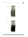
1.4.
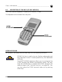
1
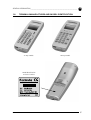
TERMINAL MANUFACTURER AND MODEL IDENTIFICATION
37-Key models
24-Key models
Model identification
and serial number
Ed.: 06/00
3
TECHNICAL INFORMATION
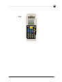
2.1.
2
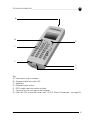
F7400 TERMINAL DESCRIPTION
The Formula 7400 is the new Hand-held PC with integrated laser scanner based on
PC technology designed by Datalogic S.p.A.
The Formula 7400 is capable of reading all common barcode symbologies.
The Formula 7400 is equipped with an IrDA port for short-range wireless infrared
communication with portable printers and other devices that support this kind of
interface
The Formula 7400 is equipped with a back-lighted LCD graphic display, 96 x 64
pixel resolution, and an ergonomic alphanumeric keyboard (24 or 37 keys).
4
Ed.: 06/00
TECHNICAL INFORMATION ______________________________________________________
2
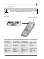
A
B
D
C
E
F
G
Key:
A) Laser beam output window
B) Programmable two-color LED
C) Keyboard
D) Protected reset button
E) F970-cradle communication window
F) Contacts for the recharging the batteries
G) Direct RS-232 connection cover (see "RS-232 Direct Connection" on page 20)
Ed.: 06/00
5
F7400 - USER MANUAL _________________________________________________________
2.2.
2
TECHNICAL CHARACTERISTICS
❏ Optical Characteristics - laser 1D
Light source laser scanner
VLD source, 670 nm
Scan rate
36 ± 3 scan/sec
Minimum resolution
0.13 mm
Skew angle
± 65°
Pitch angle
± 55°
Depth of field
30 to 800 mm
(depends on the type and density of the code)
❏ Electrical characteristics
Micro-controller
32 bit - AMD 486
Disk memory
2/4 MB (512 K used for BIOS-DOS)
RAM
2/8 MB DRAM
EEPROM
256 Bytes
Calendar/clock
quartz RTC, time and date programmable with automatic management of
leap years.
Power supply
NiMH battery pack, 1500 mAh or 3 AA
alkaline batteries.
Battery charger
Formula 970
❏ Physical characteristics
6
Technology
SMT (Surface Mounting Technology)
Dimensions (LxWxH)
176 x 61 x 36 mm
Weight
305 grams with NiMH batteries
Buzzer
piezoelectric buzzer
LED
Red/green LED
Display
high contrast display , graphic LCD
with 96x64 dot matrix, back-light
Keyboard
24 or 37 silicone covered rubber keys plus
reset.
Ed.: 06/00
TECHNICAL INFORMATION ______________________________________________________
2
❏ Environmental Conditions
Temperature
operating 0 to +45 °C;
storage (without battery) -20 to
+60 °C;
Relative Humidity
95% without condensation
Degree of protection
sealed against rain and dust
Electrostatic discharge
IEC 1000-4-2 (up to 15KV on air)
Resistance to falls
IEC 68-2-32 (up to 1.2 m on concrete)
Safety standards
IEC 825-1 class 2 laser product
CDRH class 2 laser product
❏ Programming
Operating system
DOS 6.22
Decoded bar codes - laser 1D
EAN-8, + ADD-ON-2, + ADD-ON-5
EAN-13, + ADD-ON-2, + ADD-ON-5
UPC/A, + ADD-ON-2, + ADD-ON-5
UPC/E, + ADD-ON-2, + ADD-ON-5
ITALIAN PHARMACEUTICAL
CODABAR - MONARCH - NW7 - 2 OF 7
CODE 39 STANDARD
CODE 39 FULL ASCII
CODE 39 CIP
CODE 2/5 INTERLEAVE
CODE 2/5 INDUSTRIAL
CODE 128
EAN 128
MSI
CODE 93
Ed.: 06/00
7
F7400 - USER MANUAL _________________________________________________________
2
❏ Communication characteristics
Optical Interface
IrDA 1.0
F970 Interface
cradle-terminal interface via IrDA
Cradle-Host Interface
RS-232
RS-485
Eavesdrop
Maximum speed of transmission
115 Kbit/sec max
❏ RF Communication Characteristics
Frequency
2.4 GHz
Power output
100 mW Max
In compliance with ETS 300-328
8
Ed.: 06/00
SAFETY REGULATIONS
3
Read this manual carefully before performing any type of
connection or repair on the F7400 terminal.
The user is responsible for any damages caused by incorrect use of
the equipment or by inobservance of the indication supplied in this
manual.
3.1.
GENERAL SAFETY RULES
- Use only the components supplied by the manufacturer for the specific F7400
terminal being used. The use of cradles other than those supplied with the F7400
terminal or indicated in the list in the appendix could cause serious damage to
the F7400 terminal.
- Do not attempt to disassemble the F7400 terminal, as it does not contain parts
that can be repaired by the user. Any tampering will invalidate the warranty.
-
When replacing the batteries or at the end of the operative life of the F7400
terminal, disposal must be performed in compliance with the laws in force..
-
Do not submerge the F7400 terminal in liquid products.
Ed.: 06/00
9
F7400 - USER MANUAL _________________________________________________________
3.2.
3
LASER SAFETY
Be sure the laser warning label applied to the terminal is readable
at all times. If necessary, replace it with a new one.
The laser light is visible to the human eye and is emitted from the window indicated
in the figure.
Laser beam output window
C A U T IO N
I
D
F
E
La luce laser è visibile
all’occhio umano e
viene emessa dalla finestra indicata nella figura.
Die Laserstrahlung ist
für das menschliche
Auge sichtbar und wird
am Strahlaustrittsfenster
ausgesendet (siehe Bild).
Le rayon laser est visible
à l’oeil nu et il est émis
par la fenêtre désignée
sur l’illustration dans la
figure.
a luz láser es visible al ojo
humano y es emitida por
la ventana indicada en
la figura.
LUCE LASER
NON FISSARE IL FASCIO
APPARECCHIO LASER DI
CLASSE 2
MASSIMA POTENZA
D’USCITA:
LUNGHEZZA D’ONDA
EMESSA:
CONFORME A IEC 825-1
(1993)
LASERSTRAHLUNG
NICHT IN DEN STRAHL
BLICKEN
PRODUKT DER
LASERKLASSE 2
MAXIMALE
AUSGANGSLEISTUNG:
WELLENLÄNGE:
ENTSPR. IEC 825-1
(1993)
RAYON LASER
EVITER DE REGARDER
LE RAYON
APPAREIL LASER DE
CLASSE 2
PUISSANCE DE SORTIE:
LONGUEUR D’ONDE
EMISE:
CONFORME A IEC 825-1
(1993)
RAYO LÁSER
NO MIRAR FIJO EL RAYO
APARATO LÁSER DE
CLASE 2
MÁXIMA POTENCIA DE
SALIDA:
LONGITUD DE ONDA
EMITIDA:
CONFORME A IEC 825-1
(1993)
10
Ed.: 06/00
SAFETY REGULATIONS __________________________________________________________
3
ENGLISH
The following information is provided to comply with the rules imposed by
international authorities and refers to the correct use of your terminal.
STANDARD LASER SAFETY REGULATIONS
This product conforms to the applicable requirements of both CDRH 21 CFR 1040
and IEC 825-1 at the date of manufacture.
For installation, use and maintenance, it is not necessary to open the device.
Use of controls or adjustments or performance of procedures
other than those specified herein may result in exposure to
hazardous visible laser light.
The product utilises a low-power laser diode. Although staring directly at the laser
beam momentarily causes no known biological damage, avoid staring at the beam
as one would with any very strong light source, such as the sun. Avoid that the laser
beam hits the eye of an observer, even through reflective surfaces such as mirrors,
etc.
ITALIANO
Le seguenti informazioni vengono fornite dietro direttive delle autorità
internazionali e si riferiscono all’uso corretto del terminale.
NORMATIVE STANDARD PER LA SICUREZZA LASER
Questo prodotto risulta conforme alle normative vigenti sulla sicurezza laser alla
data di produzione: CDRH 21 CFR 1040 e IEC 825-1.
Non si rende mai necessario aprire l’appa-recchio per motivi di installazione, utilizzo
o manutenzione.
L’utilizzo di procedure o regolazioni differenti da quelle descritte
nella documentazione può provocare un’esposizione pericolosa a
luce laser visibile.
Il prodotto utilizza un diodo laser a bassa potenza. Sebbene non siano noti danni
riportati dall’occhio umano in seguito ad una esposizione di breve durata, evitare
di fissare il raggio laser così come si eviterebbe qualsiasi altra sorgente di luminosità
intensa, ad esempio il sole. Evitare inoltre di dirigere il raggio laser negli occhi di un
osservatore, anche attraverso superfici riflettenti come gli specchi.
Ed.: 06/00
11
F7400 - USER MANUAL _________________________________________________________
3
DEUTSCH
Die folgenden Informationen stimmen mit den Sicherheitshinweisen überein, die
von internationalen Behörden auferlegt wurden, und sie beziehen sich auf den
korrekten Gebrauch vom Terminal.
NORM FÜR DIE LASERSICHERHEIT
Dies Produkt entspricht am Tag der Herstellung den gültigen IEC 825-1 und CDRH
21 CFR 1040 Normen für die Lasersicherheit.
Es ist nicht notwendig, das Gerät wegen Betrieb oder Installations-, und
Wartungs-arbeiten zu öffnen.
Jegliche Änderungen am Gerät sowie Vorgehensweisen, die nicht
in dieser Betriebsanleitung beschrieben werden, können ein
gefährliches Laserlicht verursachen.
Der Produkt benutzt eine Laserdiode. Obwohl zur Zeit keine Augenschäden von
kurzen Einstrahlungen bekannt sind, sollten Sie es vermeiden für längere Zeit in den
Laserstrahl zu schauen, genauso wenig wie in starke Lichtquellen (z.B. die Sonne).
Vermeiden Sie es, den Laserstrahl weder gegen die Augen eines Beobachters, noch
gegen reflektierende Oberflächen zu richten.
FRANÇAIS
Les informations suivantes sont fournies selon les règles fixées par les autorités
internationales et se refèrent à une correcte utilisation du terminal.
NORMES DE SECURITE LASER
Ce produit est conforme aux normes de sécurité laser en vigueur à sa date de
fabrication: CDRH 21 CFR 1040 et IEC 825-1.
Il n’est pas nécessaire d’ouvrir l’appareil pour l’installation, l’utilisation ou
l’entretien.
L’utilisation de procédures ou réglages différents de ceux donnés
ici peut entrainer une dangereuse exposition à lumière laser visible.
Le produit utilise une diode laser. Aucun dommage aux yeux humains n’a été
constaté à la suite d’une exposition au rayon laser. Eviter de regarder fixement le
rayon, comme toute autre source lumineuse intense telle que le soleil. Eviter aussi
de diriger le rayon vers les yeux d’un observateur, même à travers des surfaces
réfléchissantes (miroirs, par exemple).
12
Ed.: 06/00
SAFETY REGULATIONS __________________________________________________________
3
ESPAÑOL
Las informaciones siguientes son presentadas en conformidad con las disposiciones
de las autoridades internacionales y se refieren al uso correcto del terminal.
NORMATIVAS ESTÁNDAR PARA LA SEGURIDAD LÁSER
Este aparato resulta conforme a las normativas vigentes de seguridad láser a la
fecha de producción: CDRH 21 CFR 1040 y IEC 825-1.
No es necesario abrir el aparato para la instalación, la utilización o la manutención.
La utilización de procedimientos o regulaciones diferentes de
aquellas describidas en la documentación puede causar una
exposición peligrosa a la luz láser visible.
El aparato utiliza un diodo láser a baja potencia. No son notorios daños a los ojos
humanos a consecuencia de una exposición de corta duración. Eviten de mirar fijo
el rayo láser así como evitarían cualquiera otra fuente de luminosidad intensa, por
ejemplo el sol. Además, eviten de dirigir el rayo láser hacia los ojos de un
observador, también a través de superficies reflectantes como los espejos.
3.3.
FCC COMPLIANCE - INFORMATION FOR THE USER
This device complies with PART 15 of the FCC Rules. Operation is
subject to the following two conditions: (1) This device may not
cause harmful interference, and (2) this device must accept any
interference received, including interference which may cause
undesired operation.
This equipment has been tested and found to comply with the limits for a Class A
digital device, pursuant to part 15 of the FCC Rules. These limits are designed to
provide reasonable protection against harmful interference when the equipment is
operated in a commercial environment. This equipment generates, uses, and can
radiate radio frequency energy and, if not installed and used in accordance with the
instruction manual, may cause harmful interference to radio communications.
Operation of this equipment in a residential area is likely to cause harmful
interference in which case the user will be required to correct the interference at
his own expense.
Ed.: 06/00
13
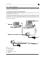
CONNECTIONS
4.1.
4
CRADLES
With the F7400 terminal, both the standard cradle F970 and the vehicle version can
be used.
C
A
B
D
E
D
Key F970 cradle:
A) IrDA window
B) Two-color LED – spare battery slot
C) F7400 terminal battery - recharge contacts
D) Connectors for host computer connections
E) Power jack
14
Ed.: 06/00
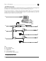
CONNECTIONS ________________________________________________________________
4
A
B
Key F970 vehicle cradle:
A) Cradle retaining clip
B) Metal bracket
Ed.: 06/00
15
F7400 - USER MANUAL _________________________________________________________
4
4.1.1. F970 Cradle
The F970 cradle is a battery charger and also functions as a serial communication interface between the host computer and the IrDA optical interface on the F7400 terminal.
By inserting the F7400 terminal into the
cradle as shown in the figure, its batteries can
be charged.
The LED indicates the status of the batteries in
the terminal:
COLOR
Constant red
Flashing
red/green
Constant
green:
DESCRIPTION
Battery charging
Battery charged, F7400 terminal on
Battery charged, F7400 terminal off or not inserted in
the cradle
LED
16
Ed.: 06/00
CONNECTIONS ________________________________________________________________
4
4.1.2. F970 Vehicle Cradle
The F970 vehicle cradle has the same functions as the F970 standard cradle in terms of
battery charging and serial communication interfacing.
The F970 vehicle cradle comes with its accessories already assembled. To install it
inside a vehicle driving compartment, proceed as follows:
1 - Simply mount the metal bracket;
2 - It must have a stabilised power supply, connected to the vehicle’s battery. The
power supply must have the following output characteristics:
Voltage
min. 9Vdc
max. 12Vdc
Power
min. 11W
Coaxial Socket
Polarity:
positive external, negative internal
Mechanical dimensions: External diameter: 5.5 mm
Internal diameter: 2.1 mm
Metal plug length:
14 mm
Do not connect the cradle directly to the vehicle’s battery.
Possible voltage surges can damage the cradle or cause it to
malfunction.
3 - Insert the F7400 terminal only after
mounting the cradle in the vehicle.
Ed.: 06/00
17
F7400 - USER MANUAL _________________________________________________________
4
4 - To take out the F7400 terminal from the
F970 vehicle cradle, you must first press the
plastic retaining clip shown in the figure
and pull the F7400 terminal upwards.
18
Ed.: 06/00
CONNECTIONS ________________________________________________________________
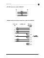
4.2.
4
TERMINAL CONNECTION TO THE HOST COMPUTER
Before continuing with this phase, be sure both the computer and
the F7400 terminal are turned off.
4.2.1.
RS-232 Connection via Cradle
To connect the cradle F970 to the host computer proceed as follows:
1 - connect the serial port of the host computer to cable 94A054000 for 9-pin
connections or to cable 94A054010 for 25-pin connections;
2 - connect the other end of the same cable (RJ connector) to the RS-232 port of
the cradle;
3 - insert the power-supply plug into the outlet on the base of the cradle;
4 - attach the power supply to a power outlet
5 - turn on the cradle and the computer.
6 - put the F7400 terminal into its cradle.
94A054000
(94A054010)
A
B
FPS14
C
Key:
A) Host computer
B) Cradle F970
C) Cradle power supply
Ed.: 06/00
19
F7400 - USER MANUAL _________________________________________________________
4
4.2.2. RS-232 Direct Connection
You can connect the F7400 terminal directly to the host computer. Proceed as
follows:
A
B
94A054240
Null Modem
Adapter Cable
C
Key:
A) Host computer
B) F7400 terminal
C) RS-232 Direct Connection Kit
20
Ed.: 06/00
CONNECTIONS ________________________________________________________________
4
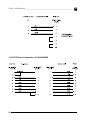
4.2.3. Other Connections
The use of the following connections depends upon the application program
loaded on the F7400 terminal.
❏ Connection with the Eavesdrop Interface
The cable Kit 94A054030 provides two cables; one for Eavesdrop connections and
one for Modem connections.
The Eavesdrop connection enables the F7400 terminal to be connected to an existing
asynchronous RS-232 line (for example between host computer and Video terminal).
The Modem connection enables the F7400 terminal to be connected to a host
system using a modem.
B
C
94A054000
(94A054010)
Eavesdrop Cable
A
FPS14
D
Modem Cable
E
FPS14
Key:
A) Video terminal
B) Host Computer
C) Cradle F970
D) Cradle power supply
E) Modem
Ed.: 06/00
21
F7400 - USER MANUAL _________________________________________________________
4
❏ RS-485 Connection
Allows for the connection of several terminals on a single RS-232 line through the
installation of a Sysnet network (see “Formula 904/N User Manual”).
If the Sysnet network is made using the Formula 902 T-Box, up to 32 Formula
cradles can be connected, including different types (if multiple cradles are used, the
individual work stations must be counted.
94A054000
(94A054000)
A
Formula 904/N
Power Supply
94A054020
E
(*)
Formula 902
B
C
Formula 902
B
94A054020
(*)
FPS14
D
B
Formula 902
C
94A054020
FPS14
D
Key:
A) Host computer
B) Formula 902 T-box
C) Cradle F970
D) Cradle power supply
E) Formula 904/N Interconverter
(*) Telephone pair (max. 125 m)
22
Ed.: 06/00
CONNECTIONS ________________________________________________________________
4
❏ RF Connection
F7400 RF versions can communicate with the host using the on-board radio
frequency module and an Access Point connected to the host computer.
A
B
Key:
A) F7400
B) Access Point
Ed.: 06/00
23
F7400 - USER MANUAL _________________________________________________________
4.3.
4
CONNECTION CABLES
Several types of cables are available depending on the type of computer and
connection.
The following cables and cable Kits are listed with their order number.
❏ RS-232 Connection with PC/AT or compatible: cable 94A054000
❏ RS-232 Connection with PC/XT or compatible: cable 94A054010
24
Ed.: 06/00
CONNECTIONS ________________________________________________________________
4
❏ RS-485 Connection: cable 94A054020
❏ Modem and/or Eavesdrop Connections: cable Kit 94A054030
Ed.: 06/00
25
F7400 - USER MANUAL _________________________________________________________
4
❏ RS-232 Direct Connection: Kit 94A054240
26
Ed.: 06/00
BIOS SETUP MENU
5.1.
5
GENERAL INFORMATION
The F7400 terminal is very versatile and can be adapted to suit many special
requirements by configuring certain parameters which can be changed after the
F7400 terminal’s boot sequence.
The activities of accessing the parameters and their modification are commonly
referred to as F7400 terminal setup activities.
The parameters have their default values, which are loaded automatically during
the booting sequence if the following conditions occur:
- the first time the F7400 terminal is booted, as initial setup of the parameters
themselves;
- if, during the boot sequence, the BIOS notes that the previously-set
configuration parameters might not be complete or correct.
Ed.: 06/00
27
F7400 - USER MANUAL _________________________________________________________
5.2.
5
ACTIVATING THE SETUP PROCEDURE
The BSETUP.EXE program is the only way to modify the F7400 terminal parameters,
it is a normal DOS program and can be invoked after the F7400 terminal’s boot
sequence.
BSETUP.EXE is intended to be invoked via the NEWAUTO.BAT, but you can use it
when you want at the DOS prompt, or you can remove it from the F7400 terminal.
Note that when BSETUP.EXE program runs, the F7400 terminal has just been done
the boot sequence, so the terminal is configured with one of the following:
- CMOS table
- EEPROM table
- DEFAULT table
The CMOS table parameters are considered the correct ones; the EEPROM table is
used only if the CMOS is corrupted and the DEFAULT table, that belongs to the
BIOS code, is used if no other choice is possible.
The application has the following three options:
BSETUP -C
the program checks the status of currently loaded parameters to see
if they are the CMOS. If so, the program exits, otherwise it asks if you
want to modify them. Default is no check;
BSETUP -N
if you select this option, the program does not convert the key to the
correct value, for example, if the program is waiting for a number, you
must put the keyboard in the correct state before pressing the
number. Default is conversion enabled;
BSETUP -D
with this option you can load the DEFAULT configuration
In the NEWAUTO.BAT file it is useful to invoke “BSETUP -C”, even though the
BIOS, after the RAM test, displays information about the currently selected
parameters.
The application does not provide a method to change date/time, since you can use
the DOS commands DATE and TIME.
28
Ed.: 06/00
BIOS SETUP MENU _____________________________________________________________
5.3.
5
PASSWORD
The password mechanism is used for protecting the access to F7400 terminal
parameters.
This protection applies only to the setup procedure, so the check option “BSETUP
-C” is not protected; this means that everybody can know the nature of loaded
parameters (cmos, eeprom or factory configuration).
The application recognizes two passwords which are case sensitive:
A) user defined
B) the string "degibkdr”
If the cmos becomes invalid, the fixed (B) password provides the key to access the
setup procedure.
If a wrong password is entered, the program ends returning to the dos prompt. Notice
that the password protects only the F7400 terminal parameters, not the terminal itself.
The password can be disabled by entering a null string.
5.4.
THE SETUP MENU AND ITS CONFIGURABLE ITEMS
The actual items present in the various menus may depend on the BIOS version being
used. Be sure that BSETUP.EXE shares the same BIOS parameters and structure, which
are contained in SETUP.BIN.
The setup menu is composed of several pages, every page contains a list of items and
every item corresponds to a terminal parameter. There is also an exit page, that gives
you the chance to save or discard the modifications.
Every page has its own title, written in the upper row of the screen; note that
BSETUP.EXE substitutes the current font with a narrow one, to see all the messages on
the screen without scrolling. Every item has a title and a value (the current value), the
title is written on the left, the value on the right. The current item is characterized by
a dot between the title and the value.
You can navigate through pages, move between items and modify them. You can
recognize two types of parameters: valued and ranged. With the ranged parameters,
you must enter a valid value. Erroneous values are recognized, and you must re-enter
a correct number. Erroneous values cannot be introduced with valued parameters
because you can only select from the ones shown.
Ed.: 06/00
29
F7400 - USER MANUAL _________________________________________________________
5.5.
5
CHANGING THE VALUES OF THE MENU ITEMS
To change the values of the menu items, you must use the F7400 terminal
keyboard. To change an item, first go to its page and then select it by moving the
dot.
To change the value of the items, you will have to use the keys indicated in the table
below.
KEY
FUNCTION
[ESC]
Activates the exit page
←,→
Previous/next page
↑,↓
Previous/next item
[SPACE] [ENTER]
Valued items: change value cycling
through the valid ones
[SPACE] [ENTER]
Ranged items: enter the modify mode
[ENTER]
Ranged items: leave the modify mode
30
Ed.: 06/00
BIOS SETUP MENU _____________________________________________________________
5.6.
5
STRUCTURE OF THE SETUP PAGES FOR THE F7400 TERMINAL AND
DESCRIPTION OF THE SETUP ITEMS
The tables below describe the SETUP pages which are available as well as the SETUP
items relating to each page.
In the VALUES column, an asterisk or a value in parenthesis indicates the default
value.
5.6.1. Console
ITEM
VALUES
DESCRIPTION
NOTES
Scroll
Software
Track
Virt
Both (*)
Scrolling mode
See description of
scrolling mode for
further
information
Contrast
Ranged:1..31 (15)
LCD contrast
Bklight tout
Ranged: 1..15 (4)
Timeout (in
seconds) for the
backlight
Kbd click
Enable (*)
Disable
Keyboard click
Click freq
Ranged: 1..100 (3) Frequency
(Hertz/100) of the
keyboard click
Password
String up to 8
characters
Selection of the
new password to
enter setup
Simply press
[ENTER] to disable
the password
The CMOS value of LCD contrast represents the only parameter that can be
modified outside the BSETUP.EXE application. As a matter of fact, selecting the
contrast mode [FUNC]-[T] gives you the ability to change this value using up and
down arrows; this changing does not affect the EEPROM value.
Ed.: 06/00
31
F7400 - USER MANUAL _________________________________________________________
5
5.6.2. Devices
ITEM
VALUES
DESCRIPTION
NOTES
Cpu high
8 MHz
16 MHz(*)
32 MHz
Clock frequency in ON See description of
state
Power Management
for further
information
Com1
Off
Electrical
Elect+wake(*)
Optical
Select type and use of
COM1
uISA
Off (*)
On
Wakeup
Use of radiofrequency
module
Keyboard
On (*)
Wakeup
Enable/disable
keyboard as a wakeup
source
RTC alarm
On
Wakeup (*)
Enable/disable the
RTC Alarm as a
wakeup source
LCD suspend
On
Off (*)
If on, keeps the
display on when the
terminal goes into
SUSPEND mode
If LCD suspend is on,
it is strongly
recommended to set
the Keyboard also to
Wakeup
5.6.3. Power Management
ITEM
VALUES
DESCRIPTION
Automatic
On (*)
Off
Enable automatic power
management
Low speed
8 MHz
4 MHz
2 MHz
1 MHz (*)
Clock frequency in IDLE
state
32
Ed.: 06/00
BIOS SETUP MENU _____________________________________________________________
5
ITEM
VALUES
DESCRIPTION
High->low tout
1/8 s (*)
1/4 s
1/2 s
1s
4s
8s
16 s
Select the period without
Primary activity (see
Activities) before passing
from High speed to the
IDLE state (Low speed)
Low->sleep tout
8s
16 s (*)
32 s
1m
4m
8m
16 m
Select the period without
any activity before
passing from the IDLE
state (Low speed) to
SUSPEND (Off).
If the Automatic parameter is selected OFF, all other Power Managment
parameters have no meaning.
5.6.4. Activities
ITEM
VALUES
DESCRIPTION
Com1
Off
Primary (*)
Secondary
Indicates the level of
activity for UART/IR
interface
uISA
Off (*)
Primary
Secondary
Indicates the level of
activity for
radiofrequency module
LCD
Off
Primary (*)
Secondary
Indicates the level of
activity for video
operations (excluding
cursor blink)
Keyboard
Off
Primary (*)
Secondary
Indicates the level of
activity for keyboard
Ed.: 06/00
33
F7400 - USER MANUAL _________________________________________________________
ITEM
VALUES
DESCRIPTION
Disk
Off
Primary (*)
Secondary
Indicates the level of
activity for all
accesses to flash disk
(boot and non-boot)
5
If the Power Manegement - Automatic parameter is selected OFF, all Activities
parameters have no meaning.
5.7.
EXIT MENU
ITEM
DESCRIPTION
NOTES
CMOS + EEPROM
Save & Exit
Saves the new values in the CMOS
memory and EEPROM memory and
exits
Press [S] to activate
the function
CMOS Save & Exit
Saves the new values in the CMOS
memory and exits.
Press [C] to activate
the function
Discard
Discards the new values and exits
Press [Q] to activate
the function
Factory parameters Load the default factory values
5.8.
Press [D] to activate
the function
EXIT FROM THE SETUP PROCEDURE
To end the SETUP procedure, you will have to:
1 - Select the Exit menu by pressing [ESC]
2 - Select one of the items by pressing the correct key (an erroneus one re-enters
the setup procedure):
- If you exit with saving, a message appears notifying that the program is about
to quit, and you can choose to reboot the F7400 terminal to see the effects
of the new configuration. Remember that the F7400 terminal parameters are
used by BIOS at boot-time.
- If you exit with the “Discard” command, no change will affect CMOS and
EEPROM memories.
- If you choose the “factory parameters”, the application applies it and then
re-enters the setup procedure.
34
Ed.: 06/00
BIOS SETUP MENU _____________________________________________________________
5.9.
5
DEFAULT VALUES
The configuration parameters are saved in a particular area of memory (CMOS
RAM) which is call NON VOLATILE because it has a battery back-up that allows the
saved values to be maintained even in the event of a power failure or if the main
batteries are not available (not present/run down).
It may happen, though, that the saved values are unreliable either because the
battery back-up is run down or the data have been changed for some reason.
Only during the F7400 terminal’s boot sequence does the BIOS perform the
function tests of the CMOS RAM and of the data reliability before using them for
the F7400 terminal’s configuration: if the BIOS encounters problems of functioning
or data non-integrity, it proceeds by loading the EEPROM values into the CMOS
RAM, if the EEPROM values have never been written, it loads the default values to
allow the terminal to be used safely.
If the BIOS cannot use CMOS and/or EEPROM values, it sends a message indicating
the kind of encountered problem, you can see this message after the end of the
RAM test.
If the BIOS uses the default values, all the configuration parameters are reset to
their default values – this applies also to the PASSWORD (because it was corrupted).
You can choose to use our default configuration invoking the BSETUP.EXE
application with the “-d” option or by selecting the factory default item on the exit
page, (your password will remain valid).
Ed.: 06/00
35
USE AND FUNCTIONING
6
The use of the F7400 terminal is subordinate to the application software loaded,
whether it is provided by Datalogic, or created with the F7400 Development System.
Once an application is loaded, barcode scanning can be performed by pressing [SCAN].
6.1.
TERMINAL START-UP
The F7400 terminal comes on when the batteries are inserted and goes in low
power consumption mode when it is no longer used for more than a
programmable time-out (usually 16 seconds).
It is possible to anticipate the low power consumption mode by pressing the key
sequence [SHIFT]-[SCAN].
To wake-up the F7400 terminal, press the [SCAN] key.
You can configure the F7400 terminal so that it comes on again automatically when:
- it receives some data from the com1 serial port;
- it receives something by RF;
- any key of the keyboard is pressed.
In the Devices sub-menu of SETUP, set the parameters “com1”, “ulSA” and
“Keyboard” to “Wakeup”.
36
Ed.: 06/00
USE AND FUNCTIONING ________________________________________________________
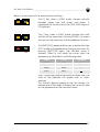
6.2.
6
BAR CODE SCANNING
To scan bar codes, point the F7400 terminal laser beam onto the code from an
adequate distance while pressing the [SCAN] key.
The lighted band emitted by the laser must completely intercept the bar code; the
LED and the emission of an acoustic signal – if enabled – will indicate that the scan
has taken place correctly.
NO
NO
OK
OK
The heat that can be felt in the area of the battery pack is not a
symptom of a malfunction; rather, it is a normal state due to the
F7400 terminal being in use.
Ed.: 06/00
37
F7400 - USER MANUAL _________________________________________________________
6.3.
6
DESCRIPTION OF THE KEYS (37-KEY MODELS)
The F7400 terminal keyboard is made up of a total of 37 keys.
The keyboard can be divided into two parts:
UPPER
KEYBOARD
MAIN
KEYBOARD
UPPER KEYBOARD
Just beneath the display are five other keys with the following functions:
[SCAN]: this key is used to turn on the bar code reader and
only becomes active if made operative by the dedicated
software.
The [SHIFT]-[SCAN] sequence allows you to anticipate the
F7400 terminal low power consumption mode. The next
time the [SCAN] key is pressed the F7400 terminal will
wake-up again (see "Terminal start-up" on page 36). You
can also make the F7400 terminal wake up by pressing
other keys.
38
Ed.: 06/00
USE AND FUNCTIONING ________________________________________________________
6
ARROW KEYS: they correspond to the arrows used to move
the cursor on a standard PC, but have the following added
functions when preceded by the [FUNC] or [SHIFT] keys:
ARROW
[FUNC]+[T]
Up
Increase the display contrast
Down
Decrease the display contrast
Left
Right
[FUNC]
Page Up
Page Down
Home
End
[SHIFT]
Scroll Up
Scroll Down
Scroll Left
Scroll Right
The [FUNC]-[ARROW] sequences emulate the Page Up/Down Home and End keys
on a PC keyboard.
The [SHIFT]-[ARROW] sequences are used to vertically and horizontally scroll
through the information displayed on the LCD display.
To keep the scroll function active for the arrow keys, activate the SCROLL function
with the [FUNC]-[Z] sequence.
Pressing the [FUNC]-[Z] sequence again will return the arrow keys to their
predefined function.
If the [FUNC]-[T] contrast mode is activated, the up and down arrows allow the
contrast of the LCD to be increased or decreased respectively. By pressing
[FUNC]-[T] again, the arrows return to normal mode.
If the words displayed appear very faint while the contrast function
is being changed, the operator will not notice if the F7400
terminal has accidentally been turned off.
Ed.: 06/00
39
F7400 - USER MANUAL _________________________________________________________
6
MAIN KEYBOARD
The main keyboard has 32 keys, among which:
[ENTER]: corresponds to the [ENTER] key on a PC.
E
N
T
E
R
GENERAL KEYS: the 28 keys that carry extra symbols;
their function changes according to the various
keyboard functions and mode
To explain their function, the key is logically divided into 4 sections according to the
following figure:
B
A
F1
&
7A
D
C
Each section corresponds to a symbol that can be obtained using the
corresponding keyboard method according to the following scheme:
A) function of the key active in NORMAL mode;
B) function of the key active in FUNC mode;
C) function of the key active in ALPHA mode;
D) function of the key active in SHIFT mode.
Some keys do not display any symbol for section D); in this case, in SHIFT mode, the
symbol in section A) is repeated.
40
Ed.: 06/00
USE AND FUNCTIONING ________________________________________________________
6
When the F7400 terminal is restarted, the keyboard is in ALPHA mode but you can
change the keyboard mode by using the SPECIAL KEYS.
SPECIAL KEYS: [ALPHA], [FUNC], [SHIFT] to change the
keyboard mode;
❏ALPHA MODE
Switches keyboard from the alphabetical ALPHA mode to the
number and symbol NORMAL mode.
The keyboard remains in this mode till the ALPHA key is
pressed again.
❏FUNC MODE
Switches keyboard to the function FUNC mode from the
ALPHA or NORMAL mode.
The keyboard remains in this mode only when the next general
key is pressed, then it returns to the previous mode.
For example, to press the [F1] key, press the [FUNC]-[A] in
sequence.
❏SHIFT MODE
On the F7400, the [SHIFT] key is not pressed at the same time
with other keys, and this function is to switch the keyboard
into the SHIFT symbols mode from the ALPHA or NORMAL
modes.
The keyboard remains in this new mode only when the next
general key is pressed, then it returns to the previous mode.
For example, to press the [&] key, press the [SHIFT]-[A] in
sequence.
Do not confuse this key with the [SHIFT] key
on a PC keyboard which is used to switch
between upper and lower case characters.
Ed.: 06/00
41
F7400 - USER MANUAL _________________________________________________________
6
❏CTRL MODE
The CONTROL mode is the same obtained by pressing the
[CTRL] key on a PC keyboard; on the F7400 it is activated
with the [SHIFT]-[FUNC] sequence from the ALPHA or
NORMAL mode.
The keyboard remains in this new mode only when the next
general key is pressed, then it returns to the previous mode.
For example, to press the [CTRL]+[C] key from the ALPHA
mode, press the [SHIFT]-[FUNC]-[C] keys in sequence.
For example, to press the [CTRL]+[F3] key, press the
[SHIFT]-[FUNC]-[FUNC]-[C] keys in sequence.
❏ALT MODE
The ALTERNATE mode is the same obtained by pressing
the [ALT] key on a PC keyboard; on the F7400 it is
activated with the [SHIFT]-[ALPHA] sequence from the
ALPHA or NORMAL mode.
The keyboard remains in this new mode only when the
next general key is pressed, then it returns to the previous
mode.
For example, to press the [ALT]+[A] key from the ALPHA
mode, press the [SHIFT]-[ALPHA]-[A] keys in sequence.
For example, to press the [ALT]+[F1] key, press the
[SHIFT]-[ALPHA]-[FUNC]-[A] keys in sequence.
HOLD
; U
42
❏HOLD MODE
The HOLD mode is obtained by pressing the [FUNC]-[U]
sequence. If [FUNC]-[U] is pressed after the ALT or CTRL
modes have been activated, the keyboard will remain in
ALT or CTRL mode for the whole key sequence until the
next sequence [SHIFT]-[ALPHA] in ALT mode or until the
[SHIFT]-[FUNC] sequence in CTRL mode.
Ed.: 06/00
USE AND FUNCTIONING ________________________________________________________
6
To summarize:
- The [SHIFT]-[FUNC] sequence is equivalent to pressing the [CTRL] key on the AT
keyboard, and the combination is valid only for the next key pressed.
- The [SHIFT]-[ALPHA] sequence is equivalent to pressing the [ALT] key on the AT
keyboard, and the combination is valid only for the next key.
- The [SHIFT]-[ALPHA]-[FUNC]-[U] sequence activates the [ALT] function for all the
successive key combinations till the [SHIFT]-[ALPHA] sequence is pressed again.
- The [SHIFT]-[FUNC]-[FUNC]-[U] sequence activates the [CTRL] function for all
successive key combinations till the [SHIFT]-[FUNC] sequence is pressed again.
- The activity of the [FUNC] and [SHIFT] keys is in mutual exclusion, and is always
valid in the [NORMAL], [ALPHA], [ALT] and [CTRL] modes.
- For example, the [FUNC]-[A] sequence is always the same as pressing the [F1]
key, whereas the [SHIFT]-[A] sequence is the same as pressing the [&] key,
independently of the ALPHA, ALT and CTRL status.
Below is a description of the remaining F7400 terminal keys:
The [SPACE] key is the same as the space bar on the AT
keyboard in NORMAL and ALPHA mode. It is the same as
pressing the [TAB] key on a PC when in FUNC mode, and the
[SHIFT]+[TAB] combination on the AT keyboard while in SHIFT
mode.
The [BS] key operates as a [Backspace] key in NORMAL mode,
an [ESC] key in FUNC mode, and as a [DEL] key in SHIFT mode.
The [FUNC]-[V] sequence changes cyclically between Upper
case and Lower case letters. It corresponds to the function of
the CAPS-LOCK key on a PC keyboard. The letters will be
displayed only with the keyboard in ALPHA mode.
The [SCROLL] key, when in FUNC mode, activates the scroll
function of the arrow keys. Pressing [FUNC]-[Z] returns the
arrow keys to their predefined function.
Ed.: 06/00
43
USE AND FUNCTIONING ________________________________________________________
STAT
[
Y
6
The [FUNC]-[Y] sequence allows you to display the state
(STAT mode) of the keyboard by changing the cursor. By
pressing [FUNC]-[Y] again, it returns to the previous one.
The cursor will take on the appearance of the pixel matrix
of the font corresponding to the codes described in the
following table:
STATE
CODE
CURSOR
ALPHA
NORMAL
FUNC
FUNC HOLD
FUNC SHIFT
SHIFT
0x41
0x4E
A
N
0x46
F
0x66
0x53
f
S
Also, if the battery level drops below a certain level, the
state of the keyboard will appear with its colors reversed.
This function depends greatly on the font chosen: if it
replaces one of the codes indicated, the cursor will take on
the appearance of the new pixel matrix.
/ X
BY pressing the [FUNC]-[X] keys, the cursor is replaced
with a BATT icon that represents the battery's charge state
or the A C character that indicates the terminal has been
inserted into the cradle. The codes used are from 251 to
255. If the sequence [FUNC]-[X] is repeated, the system
returns to the previous cursor.
Since the cursor can only indicate one state or character at
a time, when more than one cursor indication is enabled
the priority from higher to lower is:
-Show the battery state
-Show the keyboard state
-Show the DOS cursor
Ed.: 06/00
44
USE AND FUNCTIONING ________________________________________________________
6
For example:
EVENT
CURSOR
1. Power up
shows standard DOS cursor
2. Press [SHIFT]-[SP] (enable)
shows keyboard state
3. Press [SHIFT]-[ESC]
(enable)
shows battery level icon
4. Press [SHIFT]-[ESC]
(disable)
shows keyboard state
5. Press [SHIFT]-[SP] (disable)
shows standard DOS cursor
When in BATT mode, loading a new font may affect the
cursor shape.
In FUNC mode, the [W] key controls the back lighting of the
LCD display. The light will turn on for a pre-set amount of
time. If you enter the BIOS setup you can change the time
for the back lighting to remain on.
W
In FUNC mode, the [INS] key corresponds to pressing the
[INS] key on a PC keyboard.
INS
, S
This combination of keys emulates the
[CTRL]-[ALT]-[DEL] sequence of a PC
keyboard.
/ R
Ed.: 06/00
This combination of keys emulates the
[CTRL]-[BREAK] sequence of a PC keyboard.
45
F7400 - USER MANUAL _________________________________________________________
6.4.
6
DESCRIPTION OF THE KEYS (24-KEY MODELS)
The F7400 terminal keyboard is made up of a total of 24 keys.
The keyboard can be divided into two main parts.
UPPER
KEYBOARD
MAIN
KEYBOARD
UPPER KEYBOARD
Just beneath the display are five other keys with the following functions:
[SCAN]: The [SCAN} key is used to turn on the terminal and to
activate the laser scanner for bar code reading.
The [SHIFT]-[SCAN] sequence allows you to turn off the
terminal itself. Please note that is not possible to activate the
laser scanner for bar code reading if the data-collection
software application program is not currently running on the
terminal.
46
Ed.: 06/00
F7400 - USER MANUAL _________________________________________________________
6
ARROW KEYS: they correspond to the arrows
used to move the cursor on a standard PC, but
have the following added functions when
preceded by the [FUNC] or [SHIFT] keys:
ARROW
[SHIFT]+[BS]
[FUNC]
[SHIFT]
Up
Increase the display contrast
Page Up
Scroll Up
Down
Decrease the display contrast
Page Down
Scroll Down
Left
Home
Scroll Left
Right
End
Scroll Right
The [FUNC]-[ARROW] sequences emulate the Page Up/Down Home and End keys
on a PC keyboard.
The [SHIFT]-[ARROW] sequences are used to vertically and horizontally scroll
through the information displayed on the LCD display.
To keep the scroll function active for the arrow keys, activate the SCROLL function
with the [FUNC]-[:] sequence. Pressing the [FUNC]-[:] sequence again will return the
arrow keys to their predefined function.
If the [SHIFT]+[BS] contrast mode is activated, the up and down arrows allow the
contrast of the LCD to be increased or decreased respectively. By pressing
[SHIFT]+[BS] again, the arrows return to normal mode.
If the words displayed appear very faint while the contrast function
is being changed, the operator will not notice if the F7400
terminal has accidentally been turned off.
47
Ed.: 06/00
F7400 - USER MANUAL _________________________________________________________
6
MAIN KEYBOARD
The main keyboard has 19 keys, among which:
[ENTER]: corresponds to the [ENTER] key on a PC.
E
N
T
E
R
7
8
9
ABC
DEF
GHI
4
5
6
JKL
MNO
PQR
1
2
3
STU
VWX
YZ#
.
0
,;?
/
I
*
$%&
+-/
ESC
SP
TAB
BS
DEL
I
:
GENERAL KEYS: the 16 keys that carry extra symbols;
their function changes according to the various
keyboard functions and mode.
SPECIAL KEYS: [FUNC], [SHIFT] to change the keyboard
mode.
SHIFT
ALT
FUNC
CTRL
Each key can have up to five functions:
C
:
B
/
I
I
A
A) standard function of the key (NORMAL mode).
B) function of the key active in FUNC mode. Numerical Keys from 0 to 9 when in
FUNC mode, have the same function as the F10, F1, F2..F9 keys respectively on
a PC keyboard.
48
Ed.: 06/00
USE AND FUNCTIONING ________________________________________________________
6
C) functions of the key when preceeded by a SHIFT keypress (SHIFT mode). More
precisely after pressing [SHIFT]:
- Press [:] once to get the first symbol (\)
- Press [:] twice to get the second symbol (|)
- Press [:] three times to get the third symbol (_)
When you press the key the first time, the cursor is turned to the ‘\’ symbol to
show you the currently selected symbol. If you press the key again the symbol
turns to ‘|’.
To make the system accept your selection, just wait 2 seconds.
If you are inputing more than one symbol or character, as you press the next
key the operation continues. For example, to write ABC, press
[SHIFT]-[7]-[SHIFT]-[7]-[7]-[SHIFT]-[7]-[7]-[7] in sequence.
FUNC
CTRL
SHIFT
ALT
❏FUNC MODE
Switches keyboard to the function FUNC mode from the
NORMAL mode.
The keyboard remains in this mode only when the next general
key is pressed, then it returns to the previous mode.
For example, to press the [F1] key, press the [FUNC]-[1] in
sequence
❏SHIFT MODE
On the F7400, the [SHIFT] key is not pressed at the same time
with other keys. Its function is to switch the keyboard into the
SHIFT symbols mode from the NORMAL mode.
The keyboard remains in this new mode until the symbol is
accepted, then it returns to the previous mode.
For example, to press the [&] key, press the [SHIFT]-[0]-[0]-[0] in
sequence.
Do not confuse this key with the [SHIFT] key
on a PC keyboard which is used to switch
between upper and lower case characters.
Ed.: 06/00
49
F7400 - USER MANUAL _________________________________________________________
SHIFT
ALT
FUNC
CTRL
FUNC
CTRL
SHIFT
ALT
6
❏CTRL MODE
The CONTROL mode is the same obtained by pressing
the [CTRL] key on a PC keyboard. On the F7400, it is
activated with the [SHIFT]-[FUNC] sequence from the
NORMAL mode.
The keyboard remains in this new mode only when the
next general key is pressed, then it returns to the
previous mode.
For example, to press the [CTRL]+[C] key from the
NORMAL
mode,
press
the
[SHIFT]-[FUNC]-[SHIFT]-[7]-[7]-[7] keys in sequence.
For example, to press the [CTRL]+[F3] key, press the
[SHIFT]-[ FUNC]-[FUNC]-[3] keys in sequence
❏ALT MODE
The ALTERNATE mode is the same obtained by pressing
the [ALT] key on a PC keyboard. On the F7400, it is
activated with the [FUNC]-[SHIFT] sequence from the
NORMAL mode.
The keyboard remains in this new mode only when the
next general key is pressed, then it returns to the previous
mode.
For example, to press the [ALT]+[A] key from the
NORMAL mode, press the [FUNC]-[SHIFT]-[SHIFT]-[7] keys
in sequence.
For example, to press the [ALT]+[F1] key, press the
[FUNC]-[SHIFT]-[FUNC]-[1] keys in sequence.
To summarize:
- The [SHIFT]-[FUNC] sequence is equivalent to pressing the [CTRL] key on the AT
keyboard, and the combination is valid only for the next key pressed.
- The [FUNC]-[SHIFT] sequence is equivalent to pressing the [ALT] key on the AT
keyboard, and the combination is valid only for the next key.
- The activity of the [FUNC] and [SHIFT] keys is in mutual exclusion, and is always
valid in the [NORMAL], [ALT] and [CTRL] modes.
For example, the [FUNC]-[1] sequence is always the same as pressing the [F1]
key, whereas the [SHIFT]-[1] sequence is the same as pressing the [S] key,
independently of the ALT and CTRL status.
50
Ed.: 06/00
USE AND FUNCTIONING ________________________________________________________
6
Below is a description of the remaining terminal keys:
FUNC
CTRL
*
+-/
:
/
SHIFT
ALT
I
I
FUNC
CTRL
SP
TAB
The [*] key, when in FUNC mode, changes cyclically
between Upper case and Lower case letters. It
corresponds to the function of the CAPS-LOCK key on a
PC keyboard.
The [:] key, when in FUNC mode, activates the scroll
function of the arrow keys. Pressing [FUNC]-[:] a second
time returns the arrow keys to their predefined function.
The [SHIFT]-[SP] sequence allows you to display the state
(STAT mode) of the keyboard by changing the cursor. By
pressing [SHIFT]-[SP] again, the standard cursor is
restored. When in stat mode the cursor takes the
appearance as described in the following table:
STATE
CODE
CURSOR
NORMAL
0x5F
‘_’
FUNC
0xDE
‘|’
SHIFT
0xDC
‘
’
Also, if the battery level drops below a certain level, the
state of the keyboard will appear with its colors
reversed.
This function depends greatly on the font chosen: if it
replaces one of the codes indicated, the cursor will take
on the appearance of the new pixel matrix.
Ed.: 06/00
51
F7400 - USER MANUAL _________________________________________________________
SHIFT
ALT
ESC
6
By pressing the [SHIFT]-[ESC] keys, the cursor is replaced
with a BATT icon that represents the battery's charge
state or the AC character that indicates the terminal has
been inserted into the cradle. The codes used are from
251 to 255. If the sequence [SHIFT]-[ESC] is repeated,
the system returns to the previous cursor.
Since the cursor can only indicate one state or character
at a time, when more than one cursor indication is
enabled the priority from higher to lower is:
- Show the currently selected symbol or character key
(SHIFT mode) from the three possible selections
- Show the battery state
- Show the keyboard state
- Show the DOS cursor
For example:
SHIFT
ALT
ESC
EVENT
CURSOR
1. Power up
shows standard DOS
cursor
2. Press [SHIFT]-[SP] (enable)
shows keyboard state
3. Press [SHIFT]-[ESC]
(enable)
shows battery level
icon
4. Press [SHIFT]-[7]
shows A
5. Press [7]
shows B
6. Wait for 2 second timeout
shows battery level
icon
7. Press [SHIFT]-[ESC]
(disable)
shows keyboard state
8. Press [SHIFT]-[SP] (disable)
shows standard DOS
cursor
When in BATT mode, loading a new font may affect the
cursor shape.
52
Ed.: 06/00
USE AND FUNCTIONING ________________________________________________________
FUNC
CTRL
In FUNC mode, the [.] key controls the back
lighting of the LCD display. The light will
turn on for a pre-set amount of time. If you
enter the BIOS setup you can change the
time for the back lighting to remain on..
.
,;?
SHIFT
ALT
FUNC
CTRL
FUNC
CTRL
ESC
6.5.
6
SHIFT
ALT
This combination of keys emulates the
[CTRL]-[ALT]-[DEL] sequence of a PC
keyboard.
BS
DEL
This combination of keys emulates the
[CTRL]-[BREAK] sequence of a PC
keyboard.
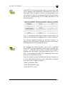
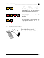
PROTECTED RESET BUTTON
To activate the reset button insert a
blunt-ended object into the hole.
The reset function will delete all RAM data.
Ed.: 06/00
53
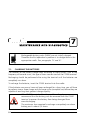
MAINTENANCE AND DIAGNOSTICS
7
Rechargeable battery packs (NiMH) are not initially charged.
Therefore the first operation to perform is to charge them in the
appropriate cradle. See paragraphs 7.2 and 4.1.
7.1.
CHARGING THE BATTERIES
The duration of the battery charge varies according to many factors, such as the
frequency of barcode scans, the type of laser scanner used on the F7400 terminal.
Recharging should be performed after using the terminal until the batteries are
completely run down.
To recharge the batteries, insert the F7400 terminal into the cradle.
If the batteries are new or have not been recharged for a long time, you will have
to perform two or three charge and discharge cycles (complete use) before they are
capable of reaching their greatest charge capacity.
If the F7400 terminal will not be used for a few days, we
recommend that the battery pack be removed from the F7400
terminal to prevent the battery from being damaged from
over-discharging.
The maximum time required to recharge a completely run-down
battery pack is about 2,5 hours.
54
Ed.: 06/00
MAINTENANCE AND DIAGNOSTICS _______________________________________________
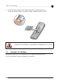
7.2.
7
REPLACING THE BATTERIES
To correctly replace the batteries, proceed as follows.
1 - Turn off the F7400 terminal.
2 - Turn the F7400 terminal over and press the lock runner as indicated in figure
below:
3 - Remove the battery pack .
Ed.: 06/00
55
F7400 - USER MANUAL _________________________________________________________
7
4 - Insert the new battery pack, keeping the lock runner pressed up.
Once the battery pack is correctly inserted, release the lock runner.
Dispose of the batteries as required by the relevant laws in force.
7.3.
CLEANING THE TERMINAL
Periodically clean the F7400 terminal with a slightly dampened cloth.
Do not use alcohol, corrosive products or solvents.
56
Ed.: 06/00
PRODUCTS AND ACCESSORIES OF THE
FORMULA 7400 LINE
A
❏ Formula 7400 Terminals
- Formula 7400 Laser Scanner
Hand-held programmable laser micro-terminal.
- Formula 7400/RF Radio Frequency Laser Handheld PC
Hand-held programmable laser micro-terminal, equipped with RF module for
radio frequency transmission.
❏ Cradle
- Formula 970 Transceiver charger
Battery charger and optical transceiver for connections between terminal and
host computer in RS-232 and RS-485.
- Formula F970 Vehicle Transceiver charger
Battery charger and optical transceiver for connections between F7400 terminal
and host computer in RS-232 and RS-485. It’s possible to install it inside a vehicle
driving compartment.
❏ Batteries
- NiMH Battery Pack
Ed.: 06/00
57
F7400 - USER MANUAL _________________________________________________________
A
❏ Software
- Development System for Formula 7400 and C Compiler
- Formula TN Client (only for F7400/RF)
Formula TN Client is a complete terminal emulation software package based on
the standard Telnet-TCP/IP protocol.
❏ Radio Frequency
- Formula One AP 7520 Ethernet
- Formula One AP 7100 ISA
58
Ed.: 06/00
TERMINAL EMULATION KEYBOARD
OVERLAYS
B
PC-LIKE
SCAN
&
F4
$
F5
!
F8
4D
F7
(
F3
%
F6
@
F9
F11
^
6F
2H
{
E
N
T
E
R
9C
5E
1G
F10
F2
8B
7A
(
F1
3
{
ALT
#
ALPHA
CTRL
I
FUNC
F12
=J
0K
L
+M
-N
O
>Q
/ R
SHIFT
TAB
< P
~
SPACE
ESC
INS
DEL
BS
HOLD
, S
: T
W
/ X
; U
? V
STAT
Ed.: 06/00
[
Y
[
Z
59
F7400 - USER MANUAL _________________________________________________________
B
VT/HP
SCAN
F1
F13
F2
8B
7A
F4
F16
F5
4D
F7
F19
F14
F17
5E
F8
F20
2H
1G
=J
&
F15
F6
F18
6F
3
CTRL
I
FUNC
0K
L
-N
O
SHIFT
TAB
BTAB
SPACE
ESC
#
< P
ALT
ALPHA
F9
$
+M
%
E
N
T
E
R
9C
F12
F11
F10
F3
>Q
INS
/ R
DEL
BS
HOLD
, S
: T
W
/ X
; U
? V
STAT
[
Y
[
Z
FUNC + SHIFT = KEY
VT-XXX
3270
SCAN
F1
F13
F2
8B
7A
F4
F16
F5
4D
F7
F19
F22
&
F11
PA1
< P
INS
F23
F3
$
F6
3
F12
PA2
>Q
F21
ALT
ALPHA
CTRL
I
FUNC
F24
L
PA3
O
EOF
CLR
SREQ
E
N
T
E
R
F18
6F
F9
-N
#
F15
9C
0K
+M
ATTN
F20
2H
=J
%
F17
5E
F8
1G
F10
F14
SHIFT
TAB
BTAB
SPACE
DEL
ESC
/ R
BS
HOLD
, S
: T
W
/ X
; U
? V
STAT
3270
60
[
Y
[
Z
FUNC + SHIFT = KEY
Ed.: 06/00
_____________________________________________________________________________
B
5250
SCAN
F1
F13
F2
8B
7A
F4
F16
F5
4D
F7
F19
F22
FLD+
F20
2H
F11
F23
$
+M
< P
INS
SREQ
, S
3
F12
5250
F21
I
FUNC
F24
SHIFT
ATTN
O
: T
TAB
BTAB
SPACE
RST
FEXT
ALT
ALPHA
CTRL
L
FLD
>Q
E
N
T
E
R
F18
6F
F9
-N
ESC
/ R
DEL
BS
HOLD CLR
; U
? V
STAT
HLP
W
F15
9C
F6
#
%
Ed.: 06/00
F3
0K
=J
&
F17
5E
F8
1G
F10
F14
/ X
[
Y
[
Z
FUNC + SHIFT = KEY
61
F7400 - USER MANUAL _________________________________________________________
B
This page has been left blank intentionally!
62
Ed.: 06/00
dichiara che
declares that the
déclare que le
bescheinigt, daß die Geräte
declara que el
Formula 7400 24K
Formula 7400 37K
Formula 7400/RF 24K
Formula 7400/RF 37K
Formula 970
Formula 970/V
Laser Hand-Held PC 24 keys
Laser Hand-Held PC 37 keys
Laser Hand-Held PC 24 keys Radio Frequency
Laser Hand-Held PC 37 keys Radio Frequency
IRDA Transceiver/Charger
IRDA Transceiver/Charger Vehicle version
sono conformi alle Direttive del Consiglio Europeo sottoelencate:
are in conformance with the requirements of the European Council Directives listed below:
sont conforme aux spécifications des Directives de l’Union Européenne ci-dessous:
der nachstehend angeführten Direktiven des Europäischen Rats:
cumple con los requisitos de las Directivas del Consejo Europeo, según la lista siguiente:
89/336/EEC
92/31/EEC
73/23/EEC
EMC Directive
EMC Directive
Low Voltage Directive
Basate sulle legislazioni degli Stati membri in relazione alla compatibilità elettromagnetica
ed alla sicurezza dei prodotti.
On the approximation of the laws of Member States relating to electromagnetic
compatibility and product safety.
Basée sur la législation des Etats membres relative à la compatibilité électromagnétique et
à la sécurité des produits.
Über die Annäherung der Gesetze der Mitgliedsstaaten in bezug auf elektromagnetische
Verträglichkeit und Produktsicherheit entsprechen.
Basado en la aproximación de las leyes de los Países Miembros respecto a la
compatibilidad electromagnética y las Medidas de seguridad relativas al producto.
Questa dichiarazione è basata sulla conformità dei prodotti alle norme seguenti:
This declaration is based upon compliance of the products to the following standards:
Cette déclaration repose sur la conformité des produits aux normes suivantes:
Diese Erklärung basiert darauf, daß das Produkt den folgenden Normen entspricht:
Esta declaración se basa en el cumplimiento de los productos con la siguientes normas:
EN 55022-B
EN 50081-1
EN 50082-1
EN 60950
EN 60825-1
EN60825
RF Emissions Control
Emission to Electromagnetic Disturbance
Immunity to Electromagnetic Disturbance
Product Safety
Safety of information tecnology
Radiation Safety of laser products
Mogliano Veneto, 29.12.98
Roberto Tunioli, Managing Director
Datalogic S.p.A
Secondary Unit - IDWare Division
Via G.Marconi, 161
Mogliano Veneto (TV) - Italia