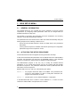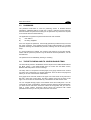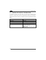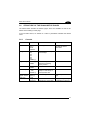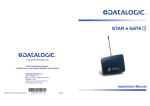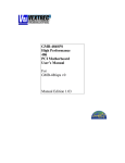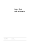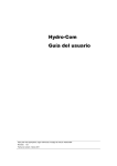
1
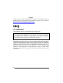
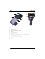
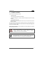
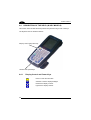
DL9600 Viper™
User’s Manual
DL9600 Viper™
User’s Manual
DL9600 Viper™
USER'S MANUAL
DATALOGIC S.p.A.
Via Candini 2
40012 - Lippo di Calderara di Reno
Bologna - Italy
DL9600 Viper™- User's Manual
Ed.: 01/2004
ALL RIGHTS RESERVED
Datalogic reserves the right to make modifications and improvements without prior notification.
Datalogic shall not be liable for technical or editorial errors or omissions contained herein, nor for incidental or
consequential damages resulting from the use of this material.
Product names mentioned herein are for identification purposes only and may be trademarks and or
registered trademarks of their respective companies.
© Datalogic S.p.A. 2001 - 2004
822000063 (Rev. C)
CONTENTS
REFERENCES ............................................................................................. v
Conventions .................................................................................................. v
Reference Documentation ............................................................................ v
Service, Support and Warranty ..................................................................... v
SAFETY REGULATIONS............................................................................ vi
General Safety Rules ....................................................................................vi
Laser Safety.................................................................................................vii
Radio Compliance.........................................................................................xi
FCC Compliance..........................................................................................xii
GENERAL VIEW ....................................................................................... xiii
1
1.1
1.2
1.3
INTRODUCTION .......................................................................................... 1
DL9600 Viper™ Terminal Description........................................................... 1
Package Contents......................................................................................... 3
Accessories................................................................................................... 4
2
2.1
2.1.1
2.1.2
2.1.3
2.2
CONNECTIONS ........................................................................................... 5
Terminal Connection to the Host Computer .................................................. 5
Connection Through CC9600 Cradle............................................................ 5
RS232 Direct Connection.............................................................................. 5
RF Connection .............................................................................................. 6
Connection Cables........................................................................................ 7
3
3.1
3.2
3.3
3.4
3.5
3.6
3.6.1
3.6.2
3.6.3
3.6.4
3.7
3.8
BIOS SETUP MENU..................................................................................... 8
General Information ...................................................................................... 8
Activating the Setup Procedure..................................................................... 8
Password ...................................................................................................... 9
The Setup Menu and its Configurable Items ................................................. 9
Changing the Values of the Menu Items ..................................................... 10
Structure of the DL9600 Setup Pages ........................................................ 11
Console....................................................................................................... 11
Devices ....................................................................................................... 13
Power.......................................................................................................... 14
Activities...................................................................................................... 15
Exit Menu .................................................................................................... 16
Exit from the Setup Procedure .................................................................... 16
4
4.1
4.2
4.2.1
USE AND FUNCTIONING .......................................................................... 17
Terminal Startup ......................................................................................... 17
Barcode Scanning....................................................................................... 18
Linear Barcode Scanning............................................................................ 18
iii
4.2.2
4.3
4.3.1
4.3.2
4.3.3
4.4
4.4.1
4.4.2
4.4.3
4.5
4.6
4.7
2D Barcode Scanning ................................................................................. 19
Description of the Keys (32-key Models)..................................................... 20
Display Control and Power Keys................................................................. 20
Key Selection .............................................................................................. 21
Special Key Sequences .............................................................................. 22
Description of the Keys (48-key Models)..................................................... 24
Display Control and Power Keys................................................................. 24
Key Selection .............................................................................................. 25
Special Key Sequences .............................................................................. 26
Control Panel .............................................................................................. 28
Status Indicators ......................................................................................... 29
File Transfer................................................................................................ 29
5
5.1
5.2
5.3
MAINTENANCE ......................................................................................... 30
Charging the Batteries ................................................................................ 30
Replacing the Batteries ............................................................................... 31
Cleaning the Terminal................................................................................. 32
6
6.1
6.2
TECHNICAL FEATURES ........................................................................... 33
Technical Data ............................................................................................ 33
Reading Diagrams ...................................................................................... 34
GLOSSARY................................................................................................ 36
INDEX ......................................................................................................... 38
iv
REFERENCES
CONVENTIONS
This manual uses the following conventions:
“User” refers to anyone using a DL9600 Viper™.
“Device” refers to the DL9600 Viper™.
“You” refers to the System Administrator or Technical Support person using this
manual to install, mount, operate, maintain or troubleshoot a DL9600 Viper™.
REFERENCE DOCUMENTATION
For further details refer to the Development System Manual of DS for Mobile@work.
SERVICE, SUPPORT AND WARRANTY
Datalogic provides several services as well as technical support through its website.
Log on to www.datalogic.com/services/support and click on the links indicated for
further information including:
-
Services – Warranty Extensions and Maintenance Agreements
Support – Software Driver Downloads
Contact Us – Listing of Datalogic Subsidiaries and Quality Partners
Authorised Repair Centres
v
SAFETY REGULATIONS
NOTE
Read this manual carefully before performing any type of connection
to the DL9600 Viper™ terminal.
The user is responsible for any damages caused by incorrect use of
the equipment or by inobservance of the indication supplied in this
manual.
GENERAL SAFETY RULES
−
Use only the components supplied by the manufacturer for the specific DL9600
Viper™ terminal being used. The use of cradles other than those supplied with
the DL9600 Viper™ terminal or indicated in the list in the appendix could cause
serious damage to the DL9600 Viper™ terminal.
−
Do not attempt to disassemble the DL9600 Viper™ terminal, as it does not
contain parts that can be repaired by the user. Any tampering will invalidate the
warranty.
−
When replacing the batteries or at the end of the operative life of the DL9600
Viper™ terminal, disposal must be performed in compliance with the laws in
force.
−
Do not submerge the DL9600 Viper™ terminal in liquid products.
vi
LASER SAFETY
The laser light is visible to the human eye and is emitted from the window indicated in
the figure.
This product complies with 21 CFR Subchapter J
CAUTION - CLASS 2
LASER LIGHT
WHEN OPEN
DO NOT STARE
INTO BEAM
AVOID EXPOSURE
LASER LIGHT
IS EMITTED FROM
THIS APERTURE
LASER LIGHT - DO NOT STARE INTO BEAM
CLASS 2 LASER PRODUCT
MAX. OUTPUT RADIATION 1.4 mW - EMITTED WAVE LENGTH 630~680 nm
EN60825-1:2001
Laser output window
Model No. DL9600 XXXXXXX
i%-5k
S/N.
DATALOGIC S.P.A.
Via Candini, 2
Calderara di Reno (BO)
Italy
!
N2468
vii
I
D
F
E
La luce laser è visibile
all'occhio umano e
viene emessa dalla
finestra indicata nella
figura.
Die Laserstrahlung ist für
das menschliche Auge
sichtbar und wird am
Strahlaustrittsfenster
ausgesendet (siehe Bild).
Le rayon laser est visible
à l'oeil nu et il est émis
par la fenêtre désignée
sur l'illustration dans la
figure.
La luz láser es visible al
ojo humano y es emitida
por la ventana indicada
en la figura.
LUCE LASER
NON FISSARE IL FASCIO
APPARECCHIO LASER DI
CLASSE 2
MINIMA POTENZA DI
USCITA:
LUNGHEZZA D'ONDA
EMESSA:
CONFORME A EN 60825-1
(2001)
LASERSTRAHLUNG
NICHT IN DER STRAHL
BLINKEN
PRODUKT DER
LASERKLASSE 2
MAXIMALE
AUSGANGLEISTUNG:
WELLENLÄNGE:
ENTSPR. EN 60825-1
(2001)
RAYON LASER
EVITER DE REGARDER
LE RAYON
APPAREIL LASER DE
CLASSE 2
PUISSANCE DE SORTIE:
LONGUER D'ONDE EMISE:
CONFORME A EN 60825-1
(2001)
RAYO LÁSER
NO MIRAR FIJO EL RAYO
APARATO LÁSER DE
CLASE 2
MÁXIMA POTENCIA DE
SALIDA:
LONGITUD DE ONDA
EMITIDA:
CONFORME A EN 60825-1
(2001)
ENGLISH
The following information is provided to comply with the rules imposed by
international authorities and refers to the correct use of your terminal.
STANDARD LASER SAFETY REGULATIONS
This product conforms to the applicable requirements of both CDRH 21 CFR 1040
and EN 60825-1 at the date of manufacture.
For installation, use and maintenance, it is not necessary to open the device.
CAUTION
Use of controls or adjustments or performance of procedures other
than those specified herein may result in exposure to hazardous
visible laser light.
The product utilizes a low-power laser diode. Although staring directly at the laser
beam momentarily causes no known biological damage, avoid staring at the beam as
one would with any very strong light source, such as the sun. Avoid that the laser
beam hits the eye of an observer, even through reflective surfaces such as mirrors,
etc.
viii
ITALIANO
Le seguenti informazioni vengono fornite dietro direttive delle autorità internazionali e
si riferiscono all’uso corretto del terminale.
NORMATIVE STANDARD PER LA SICUREZZA LASER
Questo prodotto risulta conforme alle normative vigenti sulla sicurezza laser alla data
di produzione: CDRH 21 CFR 1040 e EN 60825-1.
Non si rende mai necessario aprire l’appa-recchio per motivi di installazione, utilizzo
o manutenzione.
ATTENZIONE
L'utilizzo di procedure o regolazioni differenti da quelle descritte
nella documentazione può provocare un'esposizione pericolosa
a luce laser visibile.
Il prodotto utilizza un diodo laser a bassa potenza. Sebbene non siano noti danni
riportati dall’occhio umano in seguito ad una esposizione di breve durata, evitare di
fissare il raggio laser così come si eviterebbe qualsiasi altra sorgente di luminosità
intensa, ad esempio il sole. Evitare inoltre di dirigere il raggio laser negli occhi di un
osservatore, anche attraverso superfici riflettenti come gli specchi.
DEUTSCH
Die folgenden Informationen stimmen mit den Sicherheitshinweisen überein, die von
internationalen Behörden auferlegt wurden, und sie beziehen sich auf den korrekten
Gebrauch vom Terminal.
NORM FÜR DIE LASERSICHERHEIT
Dies Produkt entspricht am Tag der Herstellung den gültigen EN 60825-1 und CDRH
21 CFR 1040 Normen für die Lasersicherheit.
Es ist nicht notwendig, das Gerät wegen Betrieb oder Installations-, und Wartungsarbeiten zu öffnen.
ACHTUNG
Jegliche Änderungen am Gerät sowie Vorgehensweisen, die nicht
in dieser Betriebsanleitung beschrieben werden, können ein
gefährliches Laserlicht verursachen.
Der Produkt benutzt eine Laserdiode. Obwohl zur Zeit keine Augenschäden von
kurzen Einstrahlungen bekannt sind, sollten Sie es vermeiden für längere Zeit in den
Laserstrahl zu schauen, genauso wenig wie in starke Lichtquellen (z.B. die Sonne).
Vermeiden Sie es, den Laserstrahl weder gegen die Augen eines Beobachters, noch
gegen reflektierende Oberflächen zu richten.
ix
FRANÇAIS
Les informations suivantes sont fournies selon les règles fixées par les autorités
internationales et se refèrent à une correcte utilisation du terminal.
NORMES DE SECURITE LASER
Ce produit est conforme aux normes de sécurité laser en vigueur à sa date de
fabrication: CDRH 21 CFR 1040 et EN 60825-1.
Il n’est pas nécessaire d’ouvrir l’appareil pour l’installation, l’utilisation ou l’entretien.
ATTENTION
L'utilisation de procédures ou réglages différents de ceux donnés
ici peut entrainer une dangereuse exposition à lumière laser
visible.
Le produit utilise une diode laser. Aucun dommage aux yeux humains n’a été
constaté à la suite d’une exposition au rayon laser. Eviter de regarder fixement le
rayon, comme toute autre source lumineuse intense telle que le soleil. Eviter aussi
de diriger le rayon vers les yeux d’un observateur, même à travers des surfaces
réfléchissantes (miroirs, par exemple).
ESPAÑOL
Las informaciones siguientes son presentadas en conformidad con las disposiciones
de las autoridades internacionales y se refieren al uso correcto del terminal.
NORMATIVAS ESTÁNDAR PARA LA SEGURIDAD LÁSER
Este aparato resulta conforme a las normativas vigentes de seguridad láser a la
fecha de producción: CDRH 21 CFR 1040 y EN 60825-1.
No es necesario abrir el aparato para la instalación, la utilización o la manutención.
ATENCIÓN
La utilización de procedimientos o regulaciones diferentes de
aquellas describidas en la documentción puede causar una
exposición peligrosa a la luz láser visible.
El aparato utiliza un diodo láser a baja potencia. No son notorios daños a los ojos
humanos a consecuencia de una exposición de corta duración. Eviten de mirar fijo el
rayo láser así como evitarían cualquiera otra fuente de luminosidad intensa, por
ejemplo el sol. Además, eviten de dirigir el rayo láser hacia los ojos de un
observador, también a través de superficies reflectantes como los espejos.
x
RADIO COMPLIANCE
In radio systems configured with portable terminals and access points, the
frequencies to be used must be allowed by the spectrum authorities of the specific
country in which the installation takes place. Be absolutely sure that the system
frequencies are correctly set to be compliant with the spectrum requirements of the
country.
The Radio Card used in this product automatically adapts to the frequencies set by
the system and does not require any parameter settings.
NOTE
For RadioReady versions, the correct conformity label for your radio
model must be applied to the DL9600 Viper™ terminal to indicate
that the terminal is in conformity with the directives related to the
DL9600 Viper™/RF version.
Information for the User
ENGLISH
Contact the competent authority responsible for the management of radio frequency
devices of your country to verify the eventual necessity of a user license. Refer to the
web site http://europa.eu.int/comm/enterprise/rtte/spectr.htm for further information.
ITALIANO
Prendi contatto con l'autorità competente per la gestione degli apparati a radio
frequenza del tuo paese, per verificarne l'eventuale necessità della licenza d'uso.
Inoltre puoi trovare ulteriori informazioni al sito:
http://europa.eu.int/comm/enterprise/rtte/spectr.htm.
FRANÇAIS
Contactez l'autorité compétente en la gestion des appareils à radio fréquence de
votre pays pour vérifier la nécessité du permis d'usage. Pour tout renseignement
vous pouvez vous adresser au site web:
http://europa.eu.int/comm/enterprise/rtte/spectr.htm.
DEUTSCH
Um die Notwendigkeit der Verwendungslizenz zu prüfen, wenden Sie sich an die
Behörde, die auf der Radiofrequenzgerätsführung Ihres Lands bewandert ist. Weitere
Informationen sind verfügbar auf dem Web Site:
http://europa.eu.int/comm/enterprise/rtte/spectr.htm.
xi
ESPAÑOL
Contacta con la autoridad competente para la gestión de los dispositivos de radio
frecuencia de tu país, para verificar si es necesario la licencia de uso. Además se
puede encontrar mas información en el sitio web:
http://europa.eu.int/comm/enterprise/rtte/spectr.htm.
FCC COMPLIANCE
This compliance refers only to the DL9600 Viper™ batch version.
This device complies with PART 15 of the FCC Rules. Operation is subject to
the following two conditions: (1) This device may not cause harmful
interference, and (2) this device must accept any interference received,
including interference which may cause undesired operation.
This equipment has been tested and found to comply with the limits for a Class A
digital device, pursuant to part 15 of the FCC Rules. These limits are designed to
provide reasonable protection against harmful interference when the equipment is
operated in a commercial environment. This equipment generates, uses, and can
radiate radio frequency energy and, if not installed and used in accordance with the
instruction manual, may cause harmful interference to radio communications.
Operation of this equipment in a residential area is likely to cause harmful
interference in which case the user will be required to correct the interference at his
own expense.
xii
GENERAL VIEW
H
A
G
H
B
C
J
D
I
E
F
Key:
A)
B)
C)
D)
E)
F)
G)
H)
I)
J)
Good Read LED
Keyboard status/Battery low LED
Display
Charging status LED
Keyboard
Connector for direct RS232 connection and battery charging
Laser beam output window
Recharge contacts for CC9600 cradle
Trigger
IrDA port
xiii
xiv
INTRODUCTION
1
1.1
1
INTRODUCTION
DL9600 VIPER™ TERMINAL DESCRIPTION
Belonging to the Datalogic Mobile@work™ family of rugged portable terminals, the
DL9600 Viper™ is a powerful pistol grip terminal, based on PC-like architecture and
RadioReady concept. Viper™ has been conceived to match the demanding
requirements of harsh environments found in industrial applications, with no
compromises in terms of reliability and robustness. For this reason its state-of-the-art
technology is completely protected from mechanical shocks and sealed against water
and dust penetration.
Built to be an open system, Viper™ supports the most widespread mobile standards,
such as IEEE 802.11b and OpenAir, depending on the PC card used making
communication management extremely straightforward in both new and existing
installations.
The various laser scanning models offer excellent reading features including a 2D
code model that is optimized for aggressive performance on high-density PDF417
labels, RSS and other 2-D symbols including Composite Codes, and Micro PDF.
Furthermore, an innovative user interface, featuring one of the largest LCD display in
existence on a pistol grip terminal, 1/4 VGA, and a spacious, intuitive keyboard,
improves efficiency at the point of data collection.
In order to maximize functionality, Viper™ has been developed to be modular:
batteries, keyboard, scanning engine and WLAN can be shaped to meet all the
requirements of the application.
Since industrial environments are characterized by day-long use, Viper™ has been
designed with the user in mind: lightweight and well balanced together with a handfitting shape provide the best user comfort in its product class.
Communication management to the legacy system takes advantage of the new
software product line that includes terminal emulation connectivity for OS/400, Unix,
Microsoft Windows platforms, including the most used ERPs, such as SAP R/3.
Viper™ is fully supported by the Mobile@work™ CD-ROM containing a vast
assortment of Software Development Tools and Utility Programs included in the
package.
1
DL9600 VIPER™
1
H
A
G
H
B
C
J
D
I
E
F
Key:
A)
B)
C)
D)
E)
F)
G)
H)
I)
J)
2
Good Read LED
Keyboard status/Battery low LED
Display
Charging status LED
Keyboard
Connector for direct RS232 connection and battery charging
Laser beam output window
Recharge contacts for CC9600 cradle
Trigger
IrDA port
INTRODUCTION
1.2
1
PACKAGE CONTENTS
The DL9600 terminal package contains:
−
1 DL9600 terminal;
−
1 user’s manual and attached documentation;
−
1 CD-ROM Mobile@work containing Software Development System and Utility
programs
−
1 rechargeable battery pack;
−
Models including terminal emulation software may also include terminal-specific
keyboard overlays.
Any other packages will contain the accessories necessary for the DL9600 terminal
connection to the host computer and to the network: the cradle, power supply, and
one or more connection cables.
Remove all the components from their packaging, check their integrity and congruity
with the packing documents.
Keep the original packaging for use when sending products to the
technical assistance center. Damage caused by improper
packaging is not covered under the warranty.
CAUTION
Rechargeable battery packs are not initially charged. Therefore the
first operation to perform is to charge them. See paragraph 5.1.
NOTE
3
DL9600 VIPER™
1
1.3
ACCESSORIES
Cradle
94A154841 CC9600 Transceiver charger
Battery charger and optical transceiver for connections between terminal and
host computer in RS232 and RS485.
Charger
94A154840 MBC9600 multi-slot battery charger (4 slots)
Batteries
94ACC4661
94ACC4660
B-9600 LI BATTERY PACK 1800 [email protected] V
B-9600 NM BATTERY PACK 1000 [email protected] V
Software
Twin Client Terminal emulation
Power Supply
FPS18 Power Supply for CC9600 transceiver charger, DL9600 terminal (through
CAB-4001) and for the MBC9600 multi-slot battery charge r:
94ACC4595 FPS18 power supply without cord
94ACC1150 Power cord EU 3- pin
94ACC1160 Power cord AUS 3- pin
94ACC1170 Power cord USA 3- pin
94ACC1180 Power cord UK 3- pin
Cables
94A054300 cable for RS232 direct connection between the terminal and the PC.
It also provides a power jack for the connection to the FPS18.
94A054000 cable for RS232 between the CC9600 cradle and a PC/AT or
compatible.
94A054010 cable for RS232 between the CC9600 cradle and a PC/XT or
compatible.
94A054030 kit consisting of two cables for Eavesdrop and Modem connection
between cradle and Host.
4
CONNECTIONS
2
2
CONNECTIONS
2.1
TERMINAL CONNECTION TO THE HOST COMPUTER
Before continuing with this phase be sure both the computer and
the DL9600 terminal are turned off.
CAUTION
2.1.1
Connection Through CC9600 Cradle
The terminal can be connected to a Host through the CC9600 cradle by means of an
RS232 interface (with or without an Eavesdrop line), or an RS485 Multidrop interface.
See the CC9600 User Manual for details.
2.1.2
RS232 Direct Connection
You can use CAB-4001 to connect the DL9600 terminal to a host computer to
transfer data.
This cable also allows connection to an external power supply to charge the
batteries.
Key:
A) Host computer
B) DL9600 terminal
C) RS232 cable (CAB-4001)
D) Power supply
5
DL9600 VIPER™
2
2.1.3
RF Connection
DL9600 RF versions can communicate with the host using the on-board radio
frequency module and an Access Point connected to the host computer.
A
B
Key:
A) DL9600 terminal
B) Access point
6
CONNECTIONS
2.2
2
CONNECTION CABLES
The following cable is listed with its order number.
RS232 Direct Connection: CAB-4001 (cable 94A054300)
HOST/PC side
9-PIN
(female)
3
8
2
7
6
DL9600 side
7-PIN
(male)
RX
RTS
TX
CTS
DTR
VEXT
1
2
3
4
5
6
Supply jack
5
GND
7
7
DL9600 VIPER™
3
3
3.1
BIOS SETUP MENU
GENERAL INFORMATION
The DL9600 terminal is very versatile and can be adapted to suit many special
requirements by configuring certain parameters which can be changed after the
DL9600 terminal’s boot sequence.
The activities of accessing the parameters and their modification are commonly
referred to as DL9600 terminal setup activities.
The parameters have their default values, which are loaded automatically during the
booting sequence if the following conditions occur:
−
the first time the DL9600 terminal is booted, as initial setup of the parameters
themselves;
−
if, during the boot sequence, the BIOS notes that the previously-set configuration
parameters might not be complete or correct.
3.2
ACTIVATING THE SETUP PROCEDURE
The DL9600 terminal reads and applies the setup parameters at bootup.
At first the terminal reads the parameters from the CMOS RAM. If the CMOS RAM is
corrupted, the parameters are read from the EEPROM memory. If the EEPROM
memory is corrupted too, default values are applied to all the parameters.
The BSETUP.EXE program is the only way to modify the DL9600 terminal
parameters, it is a normal DOS program and can be invoked after the DL9600
terminal boot sequence. The parameter modifications made by BSETUP.EXE take
effect at the next boot sequence.
BSETUP.EXE can be run with one of the following two options:
BSETUP -C
the program checks the status of the CMOS. If the parameters are
incorrect, it asks whether you want to modify them. Otherwise, the
program exits. Default is no check.
BSETUP -D
with this option you can load the DEFAULT configuration.
In the NEWAUTO.BAT file it is useful to invoke “BSETUP -C”, so that if for some
reasons the CMOS RAM is corrupted the user is notified.
8
BIOS SETUP MENU
3.3
3
PASSWORD
The password mechanism is used for protecting access to DL9600 terminal
parameters. If BSETUP.EXE is run with the -C option, it will warn the user about an
eventual CMOS corruption before asking for the password. No password is required
to be warned about the CMOS memory.
The application recognizes two passwords which are case sensitive:
A)
user defined
B)
the string "degibkdr”
If the user forgets the password, the fixed (B) password provides the key to access
the setup procedure. If the CMOS becomes invalid, bsetup displays a "corrupted
password" message and disables the password, allowing the user to directly access
setup.
If a wrong password is entered, the program ends returning to the DOS prompt.
Notice that the password protects only the DL9600 terminal parameters, not the
terminal itself.
The password can be disabled by entering a null string.
3.4
THE SETUP MENU AND ITS CONFIGURABLE ITEMS
The actual items present in the BSETUP menus depend on the BSETUP.BIN file and
the BIOS version. If the BSETUP.BIN does not match with the BIOS version,
BSETUP.EXE will produce an error message.
The setup menu is composed of several pages, every page contains a list of items
and every item corresponds to a terminal parameter. There is also an exit page that
allows you to save or discard the modifications.
Every page has its own title, written in the upper row of the screen. Every item has a
title and a value (the current value). The title is written on the left, the value on the
right. The current item is characterized by a dot between the title and the value.
You can navigate through pages, move between items and modify them. You can
recognize two types of parameters: valued and ranged. With the ranged parameters,
you must enter a valid value. Erroneous values are recognized, and you must reenter a correct number. Erroneous values cannot be introduced with valued
parameters because you can only select from the ones shown.
9
DL9600 VIPER™
3
3.5
CHANGING THE VALUES OF THE MENU ITEMS
To change the values of the menu items, you must use the DL9600 terminal
keyboard. To change an item, first go to its page and then select it by moving the dot.
To change the value of the items, you will have to use the keys indicated in the table
below.
KEY
FUNCTION
[ESC]
Right Arrow
Left Arrow
Down Arrow
Up Arrow
[ENTER]
Activates the exit page
Next page
Previous page
Next item
Previous item
Valued items: change value cycling
through the valid ones
Ranged items: enter and exit the
modifying mode
10
BIOS SETUP MENU
3.6
3
STRUCTURE OF THE DL9600 SETUP PAGES
The tables below describe the SETUP pages which are available as well as the
SETUP items relating to each page.
In the VALUES column, an asterisk or a value in parenthesis indicates the default
value.
3.6.1
Console
ITEM
VALUES
DESCRIPTION
NOTES
Scroll
Fixed
Virt (*)
Track
Software
5s
10s
15s
20s
25s
30s
Disable (*)
Enable (*)
Disable
Scrolling mode
See description below
the table for further
information
Bklight tout
Key autorep
Kbd click
Click freq.
Green LED
(kybd. status/
batt. low)
Password
Enable (*)
Disable
Ranged:
1..100
(Default 3)
User
Alpha (*)
Scroll
String up to 8
characters
Timeout (in seconds) for
the backlight
Automatic repetition of
the keys by keeping
them pressed
Keyboard click
Frequency
(steps of 100 Hertz) of
the keyboard click
LED management
Selection of the new
password to enter setup
See description on next
page.
Simply press [ENTER]
to disable the password
11
DL9600 VIPER™
3
Scrolling Mode
The DL9600 has a CGA compatible display adapter and allows the application to
write on a virtual 25 lines by 80 columns display. On the other hand, the user can see
only a portion of this virtual display at a time, which we call the physical display.
The "scroll" parameter controls which portion of the virtual display is seen by the
user.
Fixed
the physical display follows the cursor vertically, long lines are
automatically wrapped. The keyboard has no effect on the physical display
position.
Virt
the physical display follows the cursor vertically; by enabling the "scroll
control" mode the arrows allow both a vertical and horizontal scroll of the
logical display.
Track
the physical display follows the cursor both vertically and horizontally; by
enabling the "scroll control" mode the arrows allow both a vertical and
horizontal scroll of the logical display.
Software the physical display position is fixed. It can be moved only by the
application software (see par. 4.3 and par. 4.4).
The "scroll control" mode is not the same as the scroll parameter
and is not selected in BSETUP but using the keyboard sequence
described in pars. 4.3.2 and 4.4.2.
NOTE
Keyboard Status/Battery Low LED
This is a bi-colored LED. The red color always signals a low battery condition while
the meaning of the green color can be selected as follows:
The "User" value causes the green LED to be managed by the application program.
The "Alpha" value causes the green LED to be lit when the keyboard is in Alpha
mode (32-key keyboard models).
The "Scroll" value causes the green LED to be lit when the keyboard is in "scroll
control" mode.
12
BIOS SETUP MENU
3.6.2
3
Devices
ITEM
VALUES
DESCRIPTION
NOTES
CPU high
8 MHz
16 MHz (*)
32 MHz
Clock frequency in ON state
See description of
Power
Management for
further information
Com 1
Elect+wake (*)
Optical
Off
Electrical
On (*)
Wakeup
On
Wakeup (*)
Disabled
Enabled
Wake Up
Always On (*)
Select type and use of COM1
Keyboard
RTC alarm
PCMCIA
Enable/disable keyboard as a
wakeup source
Enable/disable the RTC Alarm
as a wakeup source
Use of radio frequency module
PCMCIA
The "Disabled" value causes the PCMCIA to be always disabled.
The "Enabled" value causes the PCMCIA to be powered when the terminal is ON.
The "Wake Up" value causes the PCMCIA to be powered when the terminal is ON or
SUSPENDED. It wakes the terminal when it detects traffic on the radio network.
The "Always On" (*) value causes the PCMCIA to be powered when the terminal is
ON or SUSPENDED. This selection speeds up the terminal transition from
SUSPEND to ON.
13
DL9600 VIPER™
3
3.6.3
Power
ITEM
VALUES
DESCRIPTION
Automatic
On (*)
Off
1 MHz (*)
2 MHz
4 MHz
8 MHz
1/8 s (*)
1/4 s
1/2 s
1s
4s
8s
16 s
8s
16 s
32 s
1 m (*)
4m
8m
16 m
Disabled
1m
8m
16 m
32 m
1 h (*)
2h
4h
Enable automatic power management
Low speed
High->low tout
Low->sleep tout
Sleep->off tout
Clock frequency in IDLE state
Select the period without Primary activity (see
Activities) before passing from High speed to
Low speed
Select the period without any activity before
passing from the Low speed to SUSPEND.
Select the period without any activity before
passing from SUSPEND to OFF.
Automatic
If the Automatic parameter is OFF, all other Power Management parameters have no
meaning.
When the Automatic parameter is ON, the Power Management proceeds as follows:
−
after the high-low tout expires, the CPU automatically reduces its clock
frequency and passes from High speed to Low speed
−
once the CPU is in Low speed and no activity occurs, (sleep tout expires), it
enters the SUSPEND state. The CPU resumes operations when a WAKEUP
event occurs, or when the ON/OFF key or trigger are pressed.
−
When the CPU is in SUSPEND and no WAKEUP event occurs, (off timeout
expires), it enters the OFF state through which all peripherals are disabled. The
CPU resumes operation only when pressing the ON/OFF key or trigger.
14
BIOS SETUP MENU
3.6.4
3
Activities
The primary activities cause the CPU to pass to High speed, while the secondary
ones allow the CPU to stay in Low speed if they are already in this state (see par.
3.6.3).
ITEM
VALUES
DESCRIPTION
Com1
Primary (*)
Secondary
Off
Primary (*)
Secondary
Off
Primary (*)
Secondary
Off
Primary (*)
Secondary
Off
Primary (*)
Secondary
Off
Indicates the level of activity for the UART/IR
interface.
LCD
Keyboard
Disk
PCMCIA
Indicates the level of activity for video operations
(excluding cursor blink).
Indicates the level of activity for the keyboard.
Indicates the level of activity for all accesses to the
FLASH disk (boot and non-boot).
Indicates the level of activity for the radio frequency
module.
15
DL9600 VIPER™
3
3.7
EXIT MENU
ITEM
DESCRIPTION
NOTES
CMOS+EEPROM
Save & Exit
Saves the new values in the
CMOS memory and
EEPROM memory and exits.
Saves the new values in the
CMOS memory and exits.
Discards the new values and
exits.
Load the default factory
values.
Press [S] to activate the
function.
CMOS Save & Exit
Discard
Factory parameters
3.8
Press [C] to activate the
function.
Press [Q] to activate the
function.
Press [D] to activate the
function.
EXIT FROM THE SETUP PROCEDURE
To end the SETUP procedure, you will have to:
1- Select the Exit menu by pressing [ESC]
2- Select one of the items by pressing the correct key (an erroneous one re-enters
the setup procedure):
16
−
If you exit with saving, a message appears notifying that the program is
about to quit, and you can choose to reboot the DL9600 terminal to see the
effects of the new configuration. Remember that the DL9600 terminal
parameters are used by BIOS at boot-time.
−
If you exit with the “Discard” command, no change will affect CMOS and
EEPROM memories.
−
If you choose the “factory parameters”, the application applies it and then reenters the setup procedure.
USE AND FUNCTIONING
4
4
USE AND FUNCTIONING
The use of the DL9600 terminal is subordinate to the application software loaded.
Once an application is loaded, barcode scanning can be performed by pressing the
trigger button.
4.1
TERMINAL STARTUP
The DL9600 terminal turns on when the [ON/OFF] key or trigger is pressed.
For batch models, the prompt is displayed or if present the application program
starts.
For radio models, the following popup window is briefly displayed while the radio
connects with the base station:
Please Wait…
DL9600 IS
POWERING ON
The terminal goes into low power consumption mode (display off), when it is no
longer used for more than a programmable timeout (default 1 minute - par. 3.6.3). In
this mode it can be awakened (resuming operation) by external events such as
trigger press, radio transmission, etc. see par. 3.6.2).
If no external events cause wakeup, after another timeout (default 1 hour - par.
3.6.3) the terminal turns off. Upon pressing the [ON/OFF] key or trigger, the terminal
turns on as initially described.
17
DL9600 VIPER™
4
4.2
4.2.1
BARCODE SCANNING
Linear Barcode Scanning
To scan linear barcodes, point the DL9600 terminal laser beam onto the code from a
distance within the reading range while pressing the trigger. See the reading
diagrams in chapter 6 for the reading range of your model.
The lighted band emitted by the laser must completely intercept the barcode as
shown in the figure below. The Good Read LED and the emission of an acoustic
signal - if enabled - will indicate that the scan has taken place correctly.
18
USE AND FUNCTIONING
4.2.2
4
2D Barcode Scanning
To scan 2D barcodes, point the DL9600 terminal laser beam onto the code from a
distance within the reading range while pressing the trigger. See the reading
diagrams in chapter 6 for the reading range of your model.
The lighted band emitted by the laser must completely intercept the barcode as
shown in the figure below.
± 4° max
The terminal automatically recognizes the
2D code and will produce a raster pattern
which fully covers the code so that it can be
read; therefore you do not have to move the
terminal to read the code.
The Good Read LED and the emission of an acoustic signal - if enabled - will indicate
that the scan has taken place correctly.
19
DL9600 VIPER™
4
4.3
DESCRIPTION OF THE KEYS (32-KEY MODELS)
This version of the DL9600 terminal provides a keyboard having a total of 32 keys.
The keyboard can be divided as follows:
Display control
and power keys
General and special keys
4.3.1
Display Control and Power Keys
On/Off
Enters or exits the OFF state.
LIGHT
Switch on/off the display backlight.
Darkens the display contrast.
Lightens the display contrast.
20
USE AND FUNCTIONING
4.3.2
4
Key Selection
The following image shows the function, numeric and special keys provided on the
keyboard:
F9 A
, F2
SCRLE
◄
▲
I
►▼
M
FUNC
P
&
$
€
=
F7
>
F
7
S
'
F1
4
V
1
STAT Y
BKTAB
TAB
K
L
ESC
CAPSLK
O
CTRL
F6
/ F8
Alpha
]
[
Q
F5
\
%
{
(
8
T
¦
_
^
F2
5
@
DEL
)
}
R
F6
9
U
~
F3
6
W
?
!
CapsLk
H
ALT
J
*
F4
G
-
N
SHIFT
<
''
F5
;
: F3
F
+
F12 D
F11 C
F10 B
. F1
X
#
F10
2
PrtScr
3
SPC
Z INS
BKSP
ENTER
0
Some of these keys carry extra symbols and are logically divided in up to 5 sections
according to the following figure:
C
B
A
€
!
V
1
?
D
E
21
DL9600 VIPER™
4
Each section corresponds to a symbol that can be obtained using the corresponding
keyboard method according to the following scheme:
A)
function of the key when preceded by a SHIFT key press;
B)
function of the key when preceded by a FUNC key press;
C) function of the key when in Alpha mode;
D) function of the key when preceded by a CTRL key press;
E)
4.3.3
function of the key when directly pressed.
Special Key Sequences
By pressing these keys and the terminal trigger
simultaneously, a system hardware reset is performed.
M
FUNC
M
FUNC
22
SCRLE
◄
▲
The behavior of the arrow keys may be overridden by the
FUNC - E sequence. This sequence toggles the arrow
keys between the standard and the "scroll control" modes.
When in standard mode, the arrow keys perform several
functions depending on the current application running.
When in "scroll control" mode, the arrows allow scrolling
the physical display on the virtual one (see par. 3.6.1).
You can enable the green LED on the bottom left position
of the screen to signal the keyboard state (see par. 3.6.1).
H
ALT
The ALT key press preceding any keyboard key or key
sequence takes the same effect as on a standard PC.
Ex.: ALT - F8 corresponds to ALT - F8 on a PC.
O
CTRL
The CTRL key press preceding any keyboard key enables
the character positioned on the right upper part above the
key.
Ex: CTRL - 6 corresponds to the ˜ character.
N
SHIFT
The FUNC and SHIFT key press preceding any keyboard
key corresponds to the SHIFT + key press on the PC.
Ex.: FUNC - SHIFT - F5 corresponds to SHIFT - F5 on a
PC.
USE AND FUNCTIONING
O
CTRL
M
FUNC
N
SHIFT
BKTA
TAB
If the CTLPANEL.EXE TSR is run, this sequence activates it
by default (see par. 4.5 for details).
The FUNC key press preceding any keyboard key enables
the character positioned on the left upper part above the
key.
Ex: FUNC - 5 corresponds to the \ character.
M
FUNC
CAPSLK
Alpha
M
FUNC
The FUNC and CTRL key press preceding any keyboard
key corresponds to the CTRL + key press on the PC.
Ex.: FUNC - CTRL - F8 corresponds to CTRL - F8 on a PC.
The SHIFT key press preceding any keyboard key enables
the character positioned on the left upper corner of the key.
Ex: SHIFT - 5 corresponds to the % character.
STAT Y
M
FUNC
4
CAPSLK
Alpha
The Alpha key press enters a special mode through which it
is possible to digit all the alphabetic characters positioned
above the keys.
To exit the Alpha mode and return to the keyboard normal
functioning it is necessary to press the Alpha key again.
The FUNC key and Alpha key pressed in the stated
sequence when not in Alpha mode switch the case of the
characters positioned above the keys.
To use the alphabetic characters it is necessary to enter the
alpha mode.
Once the Alpha mode has been entered, press the Alpha key again
to exit this mode. Otherwise, it will not be possible to use other
keyboard functions.
NOTE
23
DL9600 VIPER™
4
4.4
DESCRIPTION OF THE KEYS (48-KEY MODELS)
This version of the DL9600 terminal provides a keyboard having a total of 48 keys.
The keyboard can be divided as follows:
Display control and power keys
General and special keys
4.4.1
Display Control and Power Keys
On/Off
Enters or exits the OFF state.
LIGHT
Switches on/off the display backlight.
Darkens the display contrast.
Lightens the display contrast.
24
USE AND FUNCTIONING
4.4.2
4
Key Selection
The following image shows the alphabetic, numeric and special keys provided on the
keyboard:
A
B
C
SCROLL
~
“
‘
E
F
G
H
]
+
-
=
_
I
J
K
L
M
N
SCRLK
PRTSC
O
P
[
>
<
U
V
;
:
\
|
Q
R
S
T
,
W
F7
&
FUNC
7
$
ESC
4
S
P
A
C
E
!
1
CAPSLK
SHIFT
8
F5
/
?
Y
Z
(
5
F2
CTRL
F6
DEL
6
BKSPC
F3
STAT
#
@
2
3
F10
)
0
INS
9
^
%
F1
TAB
.
X
F9
F8
*
F4
BREAK
D
E
N
T
E
R
ALT
Some of these keys carry extra symbols and are logically divided in up to 3 sections
according to the following figure:
B
A
F7
&
7
C
25
DL9600 VIPER™
4
Each section corresponds to a symbol that can be obtained using the corresponding
keyboard method according to the following scheme:
A)
function of the numeric key when preceded by a SHIFT key press; if
pressing an alphabetic key after the SHIFT key, it switches between lower
and upper case characters;
B)
function of the key when preceded by a FUNC key press;
C)
function of the key when directly pressed.
4.4.3
Special Key Sequences
By pressing these keys and the terminal trigger
simultaneously, a system hardware reset is performed.
SCROLL
FUNC
E
INS
CTRL
DEL
FUNC
ALT
ALT
INS
CTRL
26
The behavior of the arrow keys may be overridden by the
FUNC - E sequence. This sequence toggles the arrow
keys between the standard and the "scroll control" modes.
When in standard mode, the arrow keys perform several
functions depending on the current application running.
When in "scroll control" mode, the arrows allow scrolling
the physical display on the virtual one (see par. 3.6.1).
You can enable the green LED on the bottom left position
of the screen to signal the keyboard state (see par. 3.6.1).
BKSPC
This sequence of keys performs a software system
reset and corresponds to the combination of CTRL,
ALT, DEL on the PC. Do not press these keys
simultaneously but always in the stated sequence.
The ALT key press preceding any keyboard key or
key sequence takes the same effect as on a
standard PC.
Ex.: ALT -FUNC - 8 corresponds to ALT - F8 on a
PC.
The CTRL key press preceding any keyboard key
or key sequence takes the same effect as on a
standard PC.
Ex: CTRL - J corresponds to CTRL - J on a PC.
USE AND FUNCTIONING
4
STAT
E
N
T
E
R
FUNC
If the CTLPANEL.EXE TSR is run, this sequence
activates it by default (see par. 4.5 for details).
On the DL9600, the [SHIFT] key corresponds to the
PC one. By pressing it with alphabetic keys it allows
switching between upper and lower case characters.
If the SHFT key press precedes another numeric
key, it selects the character positioned on the left
upper corner of the key.
Ex: SHIFT - A corresponds to SHIFT - A on a PC.
SHIFT - 3 corresponds to #.
CAPSLK
SHIFT
The FUNC key press preceding any keyboard key
enables the character displayed above each key. By
pressing it with numeric keys it selects the F1-F10
function.
Ex: FUNC - J corresponds to ].
FUNC
CAPSLK
FUNC
SHIFT
If you want to toggle the keyboard case for all the
subsequent letters, use the FUNC - SHIFT
sequence. The FUNC - SHIFT sequence has no
effect on numeric keys.
27
DL9600 VIPER™
4
4.5
CONTROL PANEL
If the CTLPANEL.EXE TSR runs, it is possible to visualize the control panel on the
DL9600 display by pressing the FUNC - ENTER sequence (48-Key models) or the
FUNC - TAB sequence (32-Key models):
You can manage each item by directly pressing the following keys:
<arrow up>
<arrow down> or TAB
<left arrow>
<right arrow> or ENTER
Previous item
Next item
Previous parameter value
Next parameter value
The "cradle setup" area allows modifying the cradle communication parameters. Every
time the DL9600 is inserted into the CC9600 cradle it sends the configuration
parameters to the cradle. Then, the CC9600 resets to its default values every time the
DL9600 is extracted. It is possible to cause the cradle to ignore the new configuration
during the terminal insertion by running the CTLPANEL.EXE with the -I option.
If the terminal is powered by the serial cable or inserted into the cradle, by selecting
the virtual "Discharge" button and pressing the ENTER key on the keyboard the
discharge cycle starts.
On the lower part of the screen it is possible to view date, time and charger status
information. The charger status is shown only if the terminal is powered from the
serial cable or inserted into the cradle. The possible values are:
-
Slow charge: the temperature is too low or high to start the fast charge
-
Fast charge: the charger is working
-
End charge: the battery is fully charged and the charger is stopped
-
Discharging: the battery is being discharged
-
Failure: signals some battery charging errors
28
USE AND FUNCTIONING
4.6
4
STATUS INDICATORS
The DL9600 provides three different LEDs and a beeper signaling the terminal
status.
LED
STATUS
Charging status
(right side)
Green pulse
it goes on for a few seconds when the
external supply or the battery supply has
been recognized.
Green blinking
it blinks during slow charge.
Green constant
it is constant once the charging process has
been completed.
Red constant
it is constant while charging.
Green/Red
they turn on alternatively while discharging.
Orange blinking it blinks when a charging error has occurred.
Keyboard status/
Battery Low
(left-side)
Good Read (top)
Green constant
it is constant when the keyboard is in "scroll
control" or "alpha" mode depending on the
setup configuration.
Red blinking
it blinks when the battery is running down.
Green flashing
it flashes as soon as a code has been read.
Not all types of battery failures can be signaled by the charging status
LED.
NOTE
BEEPER
single beep
double beep
Low High Low*
STATUS
insertion into cradle.
extraction from cradle.
good read.
* this signal can be modified by the application program.
4.7
FILE TRANSFER
The WinDTP file transfer utility included on the CD-ROM allows you to perform file
transfer between the Host and DL9600 Terminal. See the DL-DTP User's Manual for
details on installation and functioning.
29
DL9600 VIPER™
5
5
MAINTENANCE
Rechargeable battery packs are not initially charged. Therefore the
first operation to perform is to charge them. See par. 5.1.
NOTE
5.1
CHARGING THE BATTERIES
The battery autonomy varies according to factors, such as the frequency of barcode
scanning, the RF usage and of BIOS settings.
When the batteries are low, the red LED positioned beneath the left lower corner of
the display blinks and a warning acoustic signal is emitted.
It is possible to recharge the batteries by placing the DL9600 in its cradle or by using
the DL9600 cable (see par. 2.1.2).
The charging process is signaled by a bi-colored charging status LED positioned
beneath the right lower corner of the display (see par. 4.6).
If the battery pack is removed from the terminal, it can be recharged by inserting it
into the multicharger or in the recharging slot available in the cradle.
NOTE
30
If the batteries are new or have not been recharged for a long time,
it is necessary to perform two or three charging and discharging
cycles (complete use) before they can reach their maximum charge
capability.
The maximum time required to recharge a completely run-down
battery pack is about 2 hours for NiMh batteries and 5 hours for
Li-Ion batteries.
MAINTENANCE
5.2
5
REPLACING THE BATTERIES
To correctly replace the batteries, proceed as follows.
1-
Turn off the DL9600 terminal.
2-
Press the lock button as indicated in the figure below:
3-
Remove the battery pack by pulling down the lower part of the handle:
31
DL9600 VIPER™
5
4-
Replace the battery pack, insert and press it back into the handle until the lock
button is automatically closed:
Dispose of the old batteries as required by the relevant laws in
force.
CAUTION
5.3
CLEANING THE TERMINAL
Periodically clean the DL9600 terminal with a slightly dampened cloth.
Do not use alcohol, corrosive products or solvents.
32
TECHNICAL FEATURES
6
6.1
6
TECHNICAL FEATURES
TECHNICAL DATA
DL9600 Std
Optical Features
Maximum resolution
Skew angle
Pitch angle
Scan rate - horizontal
Scan rate - vertical
Depth of field
Light source laser scanner
Safety class
Electrical Features
Power
DC supply
Battery pack
Internal backup battery
Hardware Features
FLASH
RAM
EEPROM
Microprocessor
Calendar/clock
Mechanical Features
Dimensions (LxWxH)
Weight
Buzzer
LED
Display
Keyboard
0.13 mm / 5 mils
± 55 °
± 65°
35 ± 5 scan/sec
DL9600 LR
DL9600 2D
0.25 mm / 10 mils
± 60°
± 65°
35 ± 5 scan/sec
0.17 mm / 6.6 mils
± 30°
± 15°
295 ± 5 scan/sec
10 ± 2 scan/sec
See reading diagrams on the next page
VLD, wavelength 630~680 nm
Class II EN 60825-1/CDHR
14 Vdc ± 5%
2 cell Li-Ion 1800 mAh@ 7.2 V (nominal), or
6 cell NiMh 1000 mAh@ 7.2 V (nominal)
Vanadium pentoxide lithium rechargeable
50 mAh
24-28 hour battery duration
2, 8, or 16 MB
2 or 8 MB
256 bytes
32 bit - AMD486
Quartz RTC, time and date programmable with automatic
management of leap years
23.5 x 10.5 x 18 cm / 9.25 x 4.13 x 7.08 in
768 g / 27.1 oz (with Li-Ion)
795 g / 28 oz (with Li-Ion and PC card)
799 g / 28.1 oz (with NiMh)
826 g / 29.1 (with NiMh and PC card)
2 piezoelectric buzzers
Keyboard Status/Battery low (two-color LED)
Charging Status (two-color LED)
Good Read (green LED)
High contrast display, graphic LCD with 320 x 240 pixel
resolution, backlight
32 silicone covered rubber keys
48 silicone covered rubber keys
33
DL9600 VIPER™
6
Environmental Features
Working temperature
Storage temperature
Humidity
Protection
ESD protection
Drop resistance
Programming Features
Operating system
RF terminal emulation
Decoded barcodes - laser 1D
-20° to +50 °C / -4° to 122 °F
-20° to +70 °C / -4° to 158 °F
90% non condensing
IP65
4 KV contact discharge, 8 KV air discharge
1.8 m / 5.9 ft
MS-DOS 6.22
VT100, VT220, IBM5250, HP700, 3270
EAN/UPC; Code 39; 2/5 Codes; Plessey;
Codabar; Code 128; MSI; Code 93; Code 11
Communication Features
Optical interface
CC9600 interface
Serial interface
RF Communication Features
Frequency
Power output
6.2
IrDA 1.0
Cradle-terminal interface via IrDA
RS232
2.4 GHz spread spectrum
In compliance with ETS 300-328
READING DIAGRAMS
Standard
Reading Zones (10° skew angle)
1.00 mm
(40 mils)
300
0.50 mm
(20 mils)
0.38 mm
(15 mils)
200
100
0.25 mm
(10 mils)
0.13 mm
(5 mils)
0.19 mm
(7.5 mils)
0
100
EAN
0.33 mm
(13 mils)
200
300
mm
100
34
200
300
400
500
600
700
800 mm
TECHNICAL FEATURES
6
Long Range
Reading Zones (10° skew angle)
0.38 mm (15 mils)
0.50 mm (20 mils)
600
400
0.25 mm
(10 mils)
200
0
200
400
600
mm
1 mm
(40 mils)
200
400
600
800
1000
1200
1400
1600
1800
2000 mm
2D
Reading Zones (10° skew angle)
150
PDF417 Code
0.17 mm
(6.6 mils)
100
50
0
50
100
0.38 mm
(15 mils)
150
mm
50
100
150
200
250
300
350
400
450 mm
35
GLOSSARY
Access Point
A device that provides transparent access between Ethernet wired networks and
IEEE 802.11 interoperable radio-equipped mobile units (MUs). Datalogic hand-held
computers, or other devices equipped with a PCMCIA slot, communicate with wired
networks using Access Points (AP). The mobile unit may roam among the APs in the
same subnet while maintaining a continuous, seamless connection to the wired
network.
Bar Code
A pattern of variable-width bars and spaces which represents numeric or
alphanumeric data in machine-readable form. The general format of a bar code
symbol consists of a leading margin, start character, data or message character,
check character (if any), stop character, and trailing margin. Within this framework,
each recognizable symbology uses its own unique format.
Baud Rate
A measure for data transmission speed.
BIOS
Basic Input Output System. A collection of ROM-based code with a standard API
used to interface with standard PC hardware.
Bit
Binary digit. One bit is the basic unit of binary information. Generally, eight
consecutive bits compose one byte of data. The pattern of 0 and 1 values within the
byte determines its meaning.
Bits per Second (bps)
Number of bits transmitted or received per second.
Byte
On an addressable boundary, eight adjacent binary digits (0 and 1) combined in a
pattern to represent a specific character or numeric value. Bits are numbered from
the right, 0 through 7, with bit 0 the low-order bit. One byte in memory can be used to
store one ASCII character.
Data Communications Equipment (DCE)
A device such as a modem that is designed to attach directly to a DTE (Data
Terminal Equipment) device.
36
Data Terminal Equipment
A device such as a terminal or printer that is designed to attach directly to a DCE
(Data Communications Equipment) device.
Decode
To recognize a bar code symbology (e.g., Codabar, Code 128, Code 3 of 9,
UPC/EAN, etc.) and analyze the content of the bar code scanned.
DOS
Disk Operating System. This is basic software that allows you to load and use
software applications on your computer.
EEPROM
Electrically Erasable Programmable Read-Only Memory. An on-board non-volatile
memory chip.
Flash Disk
Non-volatile memory for storing application and configuration files.
Host
A computer that serves other terminals in a network, providing services such as
network control, database access, special programs, supervisory programs, or
programming languages.
Liquid Crystal Display (LCD)
A display that uses liquid crystal sealed between two glass plates. The crystals are
excited by precise electrical charges, causing them to reflect light outside according
to their bias. They use little electricity and react relatively quickly. They require
external light to reflect their information to the user.
Light Emitting Diode (LED)
A low power electronic light source commonly used as an indicator light. It uses less
power than an incandescent light bulb but more than a Liquid Crystal Display (LCD).
RAM
Random Access Memory. Data in RAM can be accessed in random order, and
quickly written and read.
RF
Radio Frequency.
Terminal
A Datalogic portable computer product.
37
INDEX
A
Accessories; 4
B
Barcode Scanning; 18
2D Barcode; 19
Linear Barcode; 18
BIOS; 8
Activities; 15
Console; 11
Devices; 13
Exit Menu; 16
Exit Setup Procedure; 16
Password; 9
Power; 14
Setup Procedure; 8
Communication; 34
Electrical; 33
Environmental; 34
Hardware; 33
Mechanical; 33
Optical; 33
Programming; 34
RF Communication; 34
File Transfer; 29
G
General View; xiii
M
Maintenance; 30
Charging the Batteries; 30
Cleaning the Terminal; 32
Replacing the Batteries; 31
C
Connections; 5
Connection Cables; 7
RF Connection; 6
RS232 Direct Connection; 5
Control Panel; 28
D
DL9600 32-key Model; 20
DL9600 32-Key Model
Control and Power Keys; 20
Key Selection; 21
Special Key Sequence; 22
DL9600 48-Key Model; 24
Control and Power Keys; 24
Key Selection; 25
Special Key Sequences; 26
F
Features
38
P
Package Contents; 3
R
Reading Diagrams; 34
Reference Documentation; v
S
Safety Regulations; vi
FCC Compliance; xii
Laser Safety; vii
Radio Compliance; xi
Status Indicators; 29
T
Terminal Startup; 17
DATALOGIC S.p.A.,
Via Candini, 2
40012 - Lippo di Calderara
Bologna - Italy
dichiara che
declares that the
déclare que le
bescheinigt, daß das Gerät
declare que el
DL9600, Pistol Grip Terminal
DL9600/RR, Pistol Grip Terminal
e tutti i suoi modelli
and all its models
et tous ses modèles
und seine modelle
y todos sus modelos
sono conformi alle Direttive del Consiglio Europeo sottoelencate:
are in conformity with the requirements of the European Council Directives listed below:
sont conformes aux spécifications des Directives de l'Union Européenne ci-dessous:
den nachstehenden angeführten Direktiven des Europäischen Rats:
cumple con los requisitos de las Directivas del Consejo Europeo, según la lista siguiente:
89/336/EEC EMC Directive
e
and
et
und
y
92/31/EEC, 93/68/EEC
emendamenti successivi
further amendments
ses successifs amendements
späteren Abänderungen
succesivas enmiendas
Basate sulle legislazioni degli Stati membri in relazione alla compatibilità elettromagnetica ed alla sicurezza
dei prodotti.
On the approximation of the laws of Member States relating to electromagnetic compatibility and product
safety.
Basées sur la législation des Etates membres relative à la compatibilité électromagnétique et à la sécurité
des produits.
Über die Annäherung der Gesetze der Mitgliedsstaaten in bezug auf elektromagnetische Verträglichkeit und
Produktsicherheit entsprechen.
Basado en la aproximación de las leyes de los Países Miembros respecto a la compatibilidad
electromagnética y las Medidas de seguridad relativas al producto.
Questa dichiarazione è basata sulla conformità dei prodotti alle norme seguenti:
This declaration is based upon compliance of the products to the following standards:
Cette déclaration repose sur la conformité des produits aux normes suivantes:
Diese Erklärung basiert darauf, daß das Produkt den folgenden Normen entspricht:
Esta declaración se basa en el cumplimiento de los productos con las siguientes normas:
EN 55022, August 1994:
LIMITS AND METHODS OF MEASUREMENTS OF RADIO DISTURBANCE
CHARACTERISTICS OF INFORMATION TECHNOLOGY EQUIPMENT (ITE)
EN 61000-6-2, April 1999:
ELECTROMAGNETIC COMPATIBILITY (EMC). PART 6-2: GENERIC STANDARDS IMMUNITY FOR INDUSTRIAL ENVIRONMENTS
Lippo di Calderara, 11/07/2003
Ruggero Cacioppo
Quality Assurance Laboratory Manager
DATALOGIC S.p.A.,
Via Candini, 2
40012 - Lippo di Calderara
Bologna - Italy
03
dichiara che
declares that the
déclare que le
bescheinigt, daß das Gerät
declare que el
DL9600/RF-1, Pistol Grip Terminal
DL9600/RF-2, Pistol Grip Terminal
DL9600/RF-3, Pistol Grip Terminal
DL9600/RF-4, Pistol Grip Terminal
e tutti i suoi modelli
and all its models
et tous ses modèles
und seine modelle
y todos sus modelos
sono conformi alla Direttiva del Consiglio Europeo sottoelencata:
are in conformity with the requirements of the European Council Directive listed below:
sont conformes aux spécifications de la Directive de l'Union Européenne ci-dessous:
der nachstehenden angeführten Direktive des Europäischen Rats entsprechen:
cumple con los requisitos de la Directiva del Consejo Europeo, según la lista siguiente:
1999/5/EEC R&TTE
Questa dichiarazione è basata sulla conformità dei prodotti alle norme seguenti:
This declaration is based upon compliance of the products to the following standards:
Cette déclaration repose sur la conformité des produits aux normes suivantes:
Diese Erklärung basiert darauf, daß das Produkt den folgenden Normen entspricht:
Esta declaración se basa en el cumplimiento de los productos con las siguientes normas:
– SAFETY – PART 1: GENERAL
EN 60950-1, December 2001:
INFORMATION TECHNOLOGY EQUIPMENT
REQUIREMENTS
ETSI EN 300 328-2, December 2001:
ELECTROMAGNETIC COMPATIBILITY AND RADIO SPECTRUM MATTERS
(ERM); W IDEBAND TRANSMISSION SYSTEMS; DATA TRANSMISSION
EQUIPMENT OPERATING IN THE 2,4 GHZ ISM BAND AND USING SPREAD
SPECTRUM MODULATION TECHNIQUES; PART 2: HARMONIZED EN
COVERING ESSENTIAL REQUIREMENTS UNDER ARTICLE 3.2 OF THE
R & TTE DIRECTIVE
ETSI EN 301 489-17, September 2000:
ELECTROMAGNETIC COMPATIBILITY AND RADIO SPECTRUM MATTERS
(ERM); ELECTROMAGNETIC COMPATIBILTY (EMC) STANDARD FOR
RADIO EQUIPMENT AND SERVICES; PART 17: SPECIFIC CONDITIONS FOR
W IDEBAND DATA AND HIPERLAN EQUIPMENT
Lippo di Calderara, 26/08/2003
Ruggero Cacioppo
Quality Assurance Laboratory Manager