1
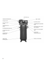
EAGLE RECIPROCATING
COMPRESSOR MANUAL
Congratulations on the purchase of your new Eagle
Compressor
2
INDEX
OWNER’S MANUAL
Introduction ....................................................................................................................................... 4
Safety ............................................................................................................................................. 4
RECEIVING YOUR COMPRESSOR
Uncrating............................................................................................................................................ 5
FREIGHT DAMAGE
Important Points................................................................................................................................. 5
INSTALLING YOUR COMPRESSOR
Location.............................................................................................................................................. 6
Mounting ............................................................................................................................................ 6
Induction System................................................................................................................................ 6
Noise .............................................................................................................................................. 6
Soldering............................................................................................................................................. 6
Power Supply and Wiring ................................................................................................................... 6
Instruction Manual............................................................................................................................. 7
SYSTEM AND COMPONENTS SELECTION
Pressure Pulsations ............................................................................................................................. 7
Piping Fitup ........................................................................................................................................ 7
Air-Cooled Heat Exchangers ............................................................................................................. 8
Safety Valves....................................................................................................................................... 8
Pressure Vessels................................................................................................................................... 8
Electrical............................................................................................................................................. 8
Guards ............................................................................................................................................. 8
Manual Relief and Shutoff Valves ...................................................................................................... 8
Warnings ........................................................................................................................................... 9
TAKING CARE OF YOUR COMPRESSOR
ADDING OIL
Sightglass Type...................................................................................................................... 9
Dip Stick Type ...................................................................................................................... 9
Checking Belt Tension ....................................................................................................................... 9
Installing New Belts............................................................................................................................ 9
Air Leaks .......................................................................................................................................... 10
Vibration........................................................................................................................................... 10
Overheating...................................................................................................................................... 10
CONTROL ADJUSTMENTS
Electric Stop/Start Operation........................................................................................................... 10
Constant Speed Control Operation ................................................................................................. 10
Dual Control Operation................................................................................................................... 11
MAINTENANCE
Daily Maintenance Recommended .................................................................................................. 11
Weekly Maintenance ....................................................................................................................... 11
Monthly Maintenance...................................................................................................................... 11
Every 90 Days ................................................................................................................................... 11
Every 180 Days ................................................................................................................................. 11
Once a Year ...................................................................................................................................... 11
OIL RECOMMENDATIONS AND SPECIFICATIONS
Recommended Oil............................................................................................................................ 12
Other Approved Oils ....................................................................................................................... 12
INITIAL START-UP OF YOUR COMPRESSOR
Checklist........................................................................................................................................... 12
Ready to Start................................................................................................................................... 13
Warning ........................................................................................................................................... 13
COMPRESSOR APPLICATION
Compressor Application................................................................................................................... 13
THE WAY IT WORKS
Single-Stage Compressors ................................................................................................................ 13
Two-Stage Compressors.................................................................................................................... 14
The Lubrication System ................................................................................................................... 14
TROUBLESHOOTING AND REPAIR
Troubleshooting and Repair ............................................................................................................. 15
3
EAGLE RECIPROCATING COMPRESSOR OWNER’S MANUAL
Introduction
In order to ensure maximum performance and long life from your new compressor, the following instructions should
be carefully read and all points regarding installation and operation of your unit should be noted and observed. Air
compressors can cause injury or death if operated improperly. A careful reading of this manual, prior to making any
connection to the motor or compressor, will pay dividends in terms of safe trouble-free operation.
Safety
At Eagle: “Safety is #1.” Your new air compressor is constructed to exacting standards of materials and workmanship. It
has been built with safety in mind. This manual is intended to pass along safety precautions that are often overlooked by
the owner, lessor or operator of our compressors.
Failure to observe the following safety precautions may result in serious injury to personnel and/or damage to property.
Eagle is not stating as fact, nor in any way implying, that the following list of Safety Precautions is an all inclusive list. When
it comes to safety, common sense and good work practices will insure safe operation.
•
•
•
•
•
•
•
•
•
•
•
•
•
•
•
4
Each section of this instruction manual, as well as any instructions supplied by manufacturers of supporting equipment,
should be read and understood prior to starting the compressor.
Never use air produced by Eagle compressors for breathing or food processing without proper filtration equipment. Air
quality must comply with all Federal, Provincial, State and local laws.
Never install a compressor in an area where children are playing or roaming freely. Children are curious and could
suffer serious burns or dismemberment.
Turn off and lock out the main power disconnect switch before attempting to work or perform any maintenance.
DO NOT attempt to service any part of the air system while it is under pressure, make sure the air has been bled
completely; isolate the air system.
Never use a flammable or toxic solvent for cleaning the air filter or any parts in direct contact with the air being
produced.
Never operate in excess of the compressor or receiver pressure rating, whichever is lower.
Never operate the compressor in excess of its rated speed.
Never operate the unit with its safety guards or shields removed.
Periodically check the pressure relief valves for proper operation, never change the pressure setting of the pressure
relief valve.
The compressor should never be operated without the pressure relief valve in place.
Never use unrated pipe, hose, or lead-tin soldering joints in any parts of the compressed air system.
Never alter any part of an Eagle air compressor. It has been designed to operate at specific speeds and conditions.
Eagle will not be responsible for any damages or injuries caused by alterations.
Make a general overall inspection of the unit daily and correct any unsafe conditions.
RECEIVING YOUR COMPRESSOR
Before uncrating inspect the following:
•
•
•
•
•
•
•
Check for possible damage in transit and see that the pulley turns freely and true by hand.
Insure that adequate lifting equipment is available for unloading and moving your compressor.
Once the compressor has been unloaded, check for concealed damage that could have occurred in transport.
Read the compressor nameplate to verify proper model and size. Read the motor nameplate to be sure the motor is
compatible with your electrical supply.
NOTE: Standard motors are open drip-proof with a maximum ambient temperature rating of 40°C. They are not
suitable for salt-laden, corrosive, dirty, wet or explosive environments. Compressors can be ordered with specialty
motors.
Check the receiver nameplate to be sure the tank is adequate for the pressure at which you intend to operate.
As a measure of safety, read the pressure relief valve setting to be sure it does not exceed the working pressure of your
air system, or air receiver.
FREIGHT DAMAGE
The entire transportation industry has adopted a modification with regard to the handling of concealed and obvious
damage claims; therefore, it is extremely important that you carefully examine every carton and crate as it comes in to your
place of business. If there is any visible damage to the shipping container, make absolutely certain the freight bill is so signed
by the delivering carrier and that you request a damage report. By handling in this manner, the damage will not be classified
as concealed and you will have no problem in making claim against the transportation firm. However, if the shipment is
accepted and then later you find that a part of the compressor has been damaged, this is classified as a concealed damage,
and the maximum time to report this damage is fifteen (15) days from time of acceptance of the freight.
Some important points to keep in mind are listed as follows:
1. With obvious damage, have the carrier make notation on freight bill at time of delivery. With concealed damage, notify
carrier within fifteen (15) days after delivery.
2. Contact carrier immediately to give them the opportunity to make an inspection of the shipment at your premises.
(With concealed damage this must occur within fifteen (15) days after delivery to the consignee.)
3. Retain containers and packing for inspection by the carrier.
4. Do not move shipments, which have been damaged, from point of carrier’s delivery to other locations, prior to
discovery and reporting of loss or damage and inspection of same.
5. Your claim should be filed with the delivery carrier within nine (9) months of the date the shipment was received, using
Standard Form for Presentation of Loss and Damage Claims. (NOTE: Damage must be reported within 15 days.)
6. Your claim will need to be substantiated with the following documents:
a) Original bill of lading
b) Original paid freight (expense) bill
c) Original invoice or certified copy
d) Other particulars obtainable in proof of loss or damage
We suggest that these instructions be circulated to your shipping and receiving personnel.
5
INSTALLING YOUR COMPRESSOR
Location
Locate the compressor in an area that is clean, well lighted, and well ventilated, with sufficient space for safe and proper
inspection and maintenance. The compressor is capable of operating in an ambient temperature up to 40°C provided that
the area is well ventilated. Inspection and maintenance checks are required daily; therefore, sufficient uncluttered space
needs to be provided around the compressor. The compressor must not be installed closer than sixteen (16) inches to a
wall or to another compressor to allow ample circulation of air across the compressor cylinders and head, and through the
coolers if they are part of the system. Additional safety can be achieved by location the pulley drive system, with the guard,
if supplied, on the wall side. Do not install the compressor in a boiler room, paint spray room or area where sandblasting
is carried out. If air in the area where the compressor is to be installed is acid-laden, or dust-laden, the compressor intake
should be piped to the outside. (See Induction System)
Mounting
Mount the compressor on a concrete pad or floor making certain that the receiver feet are level and that no stress is placed
on the legs when the mounting nuts are tightened, shim feet if necessary. Severe vibrations will result when feet are uneven
and drawn tightly to the pad, which can lead to welds cracking or fatigue failure of the receiver.
Induction System
Avoid locating the compressor air inlet system where it could ingest toxic, volatile or corrosive vapors, air temperatures
exceeding 40°C, water, or extremely dirty air. Ingesting any of the above noted atmospheres by the compressor could
jeopardize the performance of the equipment and all personnel exposed to the total compressed air system.
Depending on the size of the compressor and the size and construction of the compressor room, it may be necessary to
locate the air pickup point outside the room. This intake pipe should be increased one pipe size for every ten (10) feet of
run or any 90° elbow and the intake filters should be installed at the end of the pipes with a hood to protect them from the
elements. Destructive pulsations that will damage walls and break windows can be induced by reciprocating compressors.
Vibrations can be minimized by adding a pulsation dampener on the inlet pipe of the compressor.
Noise
Noise is a potential health hazard that must be considered. There are Local and Federal laws specifying maximum
acceptable noise levels that must not be exceeded. Most of the noise from a reciprocating compressor emanates from the
air inlet point and therefore may require a silencer. Methods that can be used to reduce noise to a listener may include,
total enclosures, walls, or moving and/or rotating the noise source. Care must be taken when erecting total enclosures or
walls because, if not properly done, they could contribute to the noise level or cause overheating problems. Contact your
authorized Eagle Distributor if assistance is required.
Soldering
Never join pipes or fittings by soldering; lead-tin solder alloys melt in the range of the compressor discharge temperature.
Silver soldering and hard soldering are forms of brazing and should not be confused with lead-tin soldering. Silver soldering
and hard soldering is brazing with silver-alloy types of filler material; this type of soldering is acceptable.
Power Supply and Wiring
Be sure that your power supply and internal wiring are adequate and that the available frequency and voltage correspond
to that on the motor nameplate. A 230-volt motor will rarely work satisfactorily on a nominal 208-volt system.
Even if the actual voltage is up to 208 volts the 10-volt to 12-volt drop during the starting period (this is an average, but
not a high figure for commercial buildings) may cause the motor to labor and blow fuses or heater elements. Do not accept
the nominal figure for line voltage, but rather measure it with a voltmeter during a period of maximum power demand.
6
If the power is “Network” distributed with 208 volts entering the building, order a 208-volt motor. If the starting voltage
is less than ninety (90) percent of the motor nameplate voltage, the motor cannot be expected to start, and the interior
building wiring must be corrected. IMPORTANT: If voltage drops lower than 188 volts a 200-volt motor should be used,
not a triple voltage (208/230/460) 3-phase motor. All 3-phase motors require external overload protection.
The wiring should be done by a licensed electrician who is familiar with the requirements of the National Board of Fire
Underwriters and of the local inspectors. Consult your local electrical contractor for electrical codes and recommended
wire sizes. Never connect 3-phase motors directly through the pressure switch. A magnetic starter of proper size c/w
overload relay is required.
Instruction Manual
Provisions must be made to have this manual readily available to the operator and maintenance personnel. If for any reason
any part of the manual becomes illegible or if the manual is lost have it replaced immediately. The instruction manual
should be periodically read to refresh one’s memory, as this may prevent a serious accident.
SYSTEM AND COMPONENTS SELECTION
Since Eagle will supply compressor packages in whole or in part, the following section provides information that will be
useful to both the installer and the assembler.
Pressure Pulsations
Total pipe length, either to or from the basic compressor, resulting in near resonant conditions can create serious problems.
Near resonant conditions occur when the pulsating flow of air in and out of the compressor cylinders is close to being
in tune with the natural frequency of the pipework, the compressor framework, and/or the surrounding structure (walls,
windows, etc.) Problems created by near resonant conditions are:
1.
2.
3.
4.
5.
6.
7.
Overloading the compressor drive unit
Compressor valve breakage
Damage to the surrounding structure
Objectionable noise
Loss of air capacity
Aftercooler damage
Fatigue failure of pipework and structural supports
Methods of correcting near resonant conditions:
1.
2.
3.
4.
Change the length of discharge and/or suction piping
Strategically locate orifices or choke tubes in the piping system being careful not to create any excessive pressure
drops.
Add a commercial pulsation dampening device
Change the compressor speed
Piping Fitup
Care must be taken to avoid assembling the piping in a strain with the compressor; it should line up without having to
spring or twist it into position. Adequate expansion loops or bends should be installed to prevent undue stresses on the
compressor resulting from the changes between hot and cold conditions. Pipe supports should be mounted independently
of the compressor and anchored as necessary to limit vibration and prevent expansion strains.
7
Air-Cooled Heat Exchangers
Air-cooled heat exchangers must be sized to provide adequate cooling under the most severe conditions, which probably
means providing for an ambient temperature of 40°C. Once the cooler is in place and working, precautions must be taken
to prevent restriction of the cooling air flow to and from the cooler and recirculation of the cooling air.
Safety Valves
Safety valves are pressure relief valves and should be sized and purchased with a pressure setting to protect the weakest link
in the system. Never change the pressure setting. Only the safety valve manufacturer or certified ASME valve repair shop
is qualified to make a change.
Safety valves are to be placed ahead of any potential blockage point which includes, but is not limited to, shutoff valves,
heat exchangers, pulsation dampeners, and discharge silencers. Ideally the safety valve should be threaded directly into the
pressure point it is sensing, not connected with tubing or pipe, and pointed away from any chance bystander.
The safety valve shall prevent pressure in the weakest component from exceeding 110% of the maximum allowable working
pressure during maximum flow conditions but must not be set higher than the maximum working pressure of the weakest
link. Failure to properly size, set and install pressure relief valves can be fatal.
Pressure Vessels
Air receiver tanks and other pressure containing vessels, such as, but not limited to, pulsation bottles, heat exchangers,
moisture separators and traps, shall be in accordance with ASME Boiler and Pressure Vessel Code, Section VIII, and/or
Provincial Boiler Branch Requirements. Failure to adhere to these codes can be fatal. Most Governments keep track of all
pressure vessels. Yours should be subject to an inspection by authorities.
Electrical
Before installation, the electrical supply should be checked for adequate wire size and transformer capacity. During
installation a suitably fused or circuit breaker disconnect switch and motor starter should be provided. Where a 3-phase
motor is used to drive a compressor any unreasonable voltage unbalance between the legs must be reduced and any low
voltage corrected to prevent excessive current draw. The installation, electric motor, wiring and all electrical controls must
be in accordance with ANSI Cl National Electric Code, ANSI C2 National Electric Safety Code, State/Provincial and
Local Codes. All electrical work should be performed by a qualified electrician. Failure to abide by the codes may result in
physical harm and/or property damage.
Guards
All mechanical action or motion is hazardous in varying degrees and needs to be guarded. Guarding shall be in compliance
with OSHA Safety and Health Standards 29 CFR 1910.219 in OSHA Manual 2206, Revised November 7, 1978 and any
Provincial, State or Local Codes.
Guards, if supplied, must be fastened in place before starting the machine and never be removed before switching off and
locking out the main power supply.
Manual Relief and Shutoff Valves
Install a manual relief valve to vent the compressor and the compressor discharge line to atmosphere. In those instances
where the air receiver tank services a single compressor, such as a tank-mounted unit, the manual relief valve can be
installed in the receiver. Where a manual shut-off valve (block valve) is used manual relief shall be installed upstream from
the manual shut-off valve (block valve), and a safety relief valve installed upstream from the manual relief valve. These
valves are to be designed and installed as to permit maintenance to be performed in a safe manner. Never substitute a check
valve for a manual shut-off valve (block valve) if it is the purpose of the manual shut-off valve to isolate the compressor
unit from a system for servicing.
8
Warnings
Warning signs and labels shall be provided with enough light to be read, be conspicuously located, and maintained for
legibility. Do not remove any warning, caution, or instructional material attached.
TAKING CARE OF YOUR COMPRESSOR
ADDING OIL
A) Sightglass Type
Most Eagle compressors are equipped with a round or oval type sightglass oil level gauge. This sightglass gauge is located
on the crankcase opposite from the flywheel end of the compressor.
•
•
•
•
•
Oil should always be visible in this sightglass, whether the compressor is operating or not.
The top of the oil level sightglass indicates the maximum oil fill, the center indicates the normal operating level when
the compressor is at speed, and the bottom indicates the low oil operating level when the compressor is at speed. This
type of level 9 gauge allows you to check your oil level without having to stop the compressor.
Always pull the motor disconnect switch to the Off position before adding oil to your compressor.
Remove the oil fill plug and slowly add oil until a small air bubble is seen at the top of the sightglass.
CAUTION: Do not overfill; if in doubt remove the oil through the drain plug and slowly refill the
compressor.
When the level has been reached, install the oil fill plug and re-start the compressor.
B) Dip Stick Type
• If your compressor is equipped with a dip stick type oil level gauge, stop and pull the motor disconnect each time you
check the oil level.
• The proper oil level is anywhere between the two marks. The top mark is the “full mark”, while the bottom mark is
the “add mark”.
• Never overfill your compressor.
Checking Belt Tension
ALWAYS TURN OFF AND LOCK OUT THE MAIN POWER DISCONNECT BEFORE WORKING ON THE BELTS
SO THE MOTOR CANNOT START UP UNEXPECTEDLY.
When belt tension is adjusted properly the belts can be depressed as follows:
•
•
•
•
•
At a point midway between the motor pulley and the flywheel, apply 4 lbs. pressure to the outer surface of the belt
using a tensioning gauge and force the belt to deflect downwards:
The normal deflection is 3/8” to 1/2”.
Loose belts will slip on the motor pulley and cause undue heat and wear. A loose belt will usually be hot and squeak.
A belt that is too tight will overload the bearings and cause irreversible damage.
Adjustments can be made by loosening the motor hold down bolts and sliding the motor along its base.
When tightening the motor to its new location, always make sure that the two pulleys are perfectly aligned.
Installing New Belts
•
•
•
•
•
When installing new belts, it is necessary that the motor bolts be loosened and the motor be moved towards the
compressor.
The new belts can then be installed without damage or strain.
As bolts will stretch, it is recommended that ALL belts be changed at the same time with matched belts.
It is recommended that the belt tension be checked again after 8 hours and 40 hours of operation.
Belt tension should be checked monthly, regardless of the amount of hours run.
9
Air Leaks
Air leaks are costly, your compressor uses a lot of energy to ensure that a constant storage of high-pressure air is available
to perform work.
•
•
If air leaks are detected, rectify the problem as soon as possible.
If a detected air leak is potentially dangerous, isolate the area and attend to it immediately.
Vibration
Vibration is a characteristic of all reciprocating machines. It can be held to a minimum by keeping the compressor securely
fastened to a solid level foundation. Isolating vibration pads should only be used with Engineering approval.
•
•
Maintain proper belt alignment
Keep nuts and bolts tight
Overheating
The compression of air generates heat, much of which is dissipated as cooling air passes over the cylinders, heads and
intercoolers. Improper rotation and dirt accumulation on compressors are the most common causes of overheating.
•
•
•
Make sure that the compressor is rotating as per the directional arrow indicated on the flywheel.
Keep your compressor cooling fins clean at all times. Cooling fins are found on intercooler tubes, cylinder heads,
cylinders etc.
Make sure room ventilation is proper; the radiant heat created by the compressor will cause the room temperature to
rise.
CONTROL ADJUSTMENTS
Electric Stop/Start Operation
Electric powered compressors are equipped with a pressure switch type control. Pressure switches are electrical devices and
should be adjusted by a qualified electrician or compressor technician.
•
•
The pressure switches provided by Eagle are pre-set at the factory and usually do not require any adjustment.
Most pressure switches supplied by Eagle will have adjustment instructions printed under the switch cover.
Constant Speed Control Operation
All gas engine driven compressors are equipped with a constant speed control pilot valve which activates a compressor
unloading device. Various types of compressor unloaders are used, they could be inlet valve unloaders (located on
compressor heads), or air outlet vent unloaders (located on compressor delivery line before the check valve.)
The control pilot valve is connected directly to the air receiver tank and on its output signal side to the compressor
unloading device. When the air signal from the pilot valve is sent to the unloading device; the compressor stops
compressing.
•
•
10
To adjust the pilot valve simply loosen the barrel locknut and rotate the barrel. Clockwise rotation will increase the
pressure while counter clockwise will decrease the pressure. Lock the barrel when proper pressure is achieved.
Gas engine driven compressors are also equipped with a air bleed off vent valve located on the check valve. To provide
for easy starting when pressure is present in the receiver tank, Simply open this vent valve allowing the compressor
discharge line to vent to atmosphere. When you are satisfied that the engine is operating at speed, close the vent valve
and the compressor will operate normally.
Dual Control Operation
When electric powered compressors are provided with “Optional” stop/start and constant speed control.
•
•
The constant speed control pilot is to be set to unload at a slightly lower pressure than the pressure switch. That is,
if your pressure switch is set to cut out at 125 PSIG. then the constant speed control pilot should be set to unload at
approximately 120 PSIG.
An isolation valve is placed in the supply line to the constant speed control pilot. This valve, when open will provide
constant speed operation and when closed stop/start operation. If you close the valve when the compressor is in the
process of unloading, it may stay unloaded in spite of falling pressure. If this occurs, simply open and reclose the valve.
MAINTENANCE
NOTE: Time frames below may need to be shortened in harsher environments.
Daily Maintenance Recommended (8 hours of operation)
1. Check oil level, add oil as required.
2. Drain moisture from tank by opening tank drain cock located in bottom of tank.
3. Turn off compressor at the end of each day’s operation. Shut off air supply by closing valve. Turn off power supply at
wall switch.
Weekly Maintenance
1. Turn power off. Clean dust and foreign matter from cylinder head, motor, fan blades, intercooler and tank.
2. Manually operate the pressure relief valves to insure proper operation.
Monthly Maintenance (160 hours of operation)
1. Remove and clean intake air filters.
2. Check V-belts for tightness (See Checking Belt Tension).
Every 90 Days (500 hours of operation)
1.
2.
3.
4.
Change crankcase oil. Use type and grade oil as specified. (See Oil Recommendation and Specification)
Check entire system for air leakage around fittings, connections and gaskets.
Tighten nuts and cap screws as required.
Replace air filter element
Every 180 Days (1000 hours of operation)
1. Check and clean compressor valves, replace springs, discs, and seats when worn or damaged. If Reed valves are used,
inspect them for cracks. Replace if required.
2. If excessive carbon build-up is found. This is an indication that the wrong oil is being used, or the compressor is
overheating.
CAUTION: Valves must be replaced in original positions. Valve gaskets should be replaced each time valves are
serviced.
3. Electric Motor or Gas Engine: For service refer to separate manual or chart attached to equipment.
Once a Year (Every 2000 hours)
1. Inspect pressure switch contacts and operation.
2. Inspect contact points in motor, if so equipped.
3. Inspect the tank for corrosion or other damage.
11
OIL RECOMMENDATION AND SPECIFICATION
Recommended Oil
Eagle Compressor Oil
# EAQIL 10 (1 Litre)
# EAOIL 40 (4 Litres)
Eagle Compressor Oil is a non-detergent mineral oil formulated with additives to help minimize carbon build-up, increase
ring life and reduce oil consumption. Regular oil changes with Eagle Compressor Oil will increase performance and life
expectancy. Manufactured for use at ambient temperatures of 0°C. to 30°C.
Other Approved Oils
Regular Mineral Oils can also be used in Eagle Compressors.
*Always use a non-detergent oil with the following specification:
•
•
•
•
The lubricant selected must have a pour point of at least 10°C lower than the minimum expected ambient
temperature.
Engine crankcase, “if gasoline engine operated,” fill in accordance with engine manufacturers’ recommendations found
in engine manual.
Electric motors are usually equipped with sealed-for-life bearings and require no additional lubrication.
Never use a multi-weight detergent motor oil in your compressor.
INITIAL START-UP OF YOUR COMPRESSOR
SAFE PRACTICES ARE MANDATORY WHEN DEALING WITH COMPRESSED AIR, THEREFORE, THE
FOLLOWING PROCEDURE SHOULD BE FOLLOWED FOR: START-UP OF A NEW INSTALLATION, START-UP
AFTER CHANGES HAVE BEEN MADE TO AN EXISTING INSTALLATION, AND START-UP AFTER SERVICE
REPAIR WORK HAS BEEN PERFORMED.
Checklist
•
•
•
•
•
•
•
•
•
12
Make sure no installation debris or tools are on or around the compressor.
Check oil level (See Adding Oil)
Check belt tension (See Checking Belt Tension)
Rotate flywheel to make sure it rotates freely
Make sure all guards are in place
Check fuses or thermal overloads for proper size
Open all manual shut-off valves
Jog the starter switch to check rotational direction of the compressor. It should rotate as per the directional arrow on
the compressor flywheel.
The rotation is right when the cooling fins inside the flywheel are blowing air towards the compressor.
Ready to Start
•
•
•
•
If the above checklist has been completed and all of the conditions are satisfied, you can now open the manual vent
valve to atmosphere and start the compressor.
Look/listen for unusual noise, failure to compress, vibration, belt slippage or overheating. If a problem is spotted stop
the compressor and correct the problem. (See trouble-shooting guide.)
Close manual vent valve slowly and allow pressure to build. Do not let pressure exceed the unload point or stop point;
hold pressure at the point where the compressor should unload with the pilot valve, or should stop with the pressure
switch. Adjust pilot valve or pressure switch to achieve the maximum desired operating pressure. The maximum
desired operating pressure must never exceed the designed pressure for the system nor should it load the motor beyond
its service factor. When satisfactory results are obtained, close the manual vent valve completely and let the system
pressure develop to the set level, then manually operate the safety relief valves. The safety relief valves should be
manually operated once a week to be sure they are functioning.
Observe temperature and pressure gauges, if supplied, closely for the first hour of operation and then frequently for the
next seven hours. After the first day, temperature, pressure, and general compressor operation should be monitored at
least once every eight hours. If any abnormal conditions are witnessed, stop the compressor and correct the problem.
Warning
Excessive speed of compressor or driver can be lethal. Never operate the compressor beyond Eagle’s recommendation.
Bursting of the flywheel may be the greatest threat. The normal guard may not contain all the pieces. Crankshaft and
connecting rod breakage is a possibility and compressor efficiency, valve life, bearing life and driver will be abnormally
reduced.
COMPRESSOR APPLICATION
All Eagle Reciprocating Compressors are High Quality industrial units. The crankcases, cylinders, and cylinder heads are
constructed of good quality cast iron. They are air-cooled, single or two stage in their design. Most single-stage compressors
are capable of delivering up to 150 PSIG, depending on speed and duty cycle; some units are built only for 120 PSIG.
Two-stage compressors can deliver up to 200 PSIG, again depending on the model, type of controls and configuration; some
two-stage units are rated for 175 PSIG operation. If you do not know the capabilities of your compressor, contact the Eagle
distributor nearest you for assistance.
The above mentioned delivery pressures are the maximum pressures at which a compressor can safely be operated in under
light duty conditions. Long or
continuous running cycles at maximum pressures will result in overheating and premature failure of your compressor.
THE WAY IT WORKS
Single-Stage Compressors
During the downstroke of the piston, air is forced into the cylinder by atmospheric pressure through an inlet filter and an
intake valve located in the head of the compressor. When the piston reaches the bottom of the stroke, the intake valve
closes; the air is now trapped in the cylinder. During the upstroke of the piston, the air is compressed in the cylinder,
the discharge valve opens and the compressed air is delivered into the air receiver tank. The total compression, from
atmospheric to the final discharge pressure, is accomplished in one stroke of the piston.
13
Two-Stage Compressors
During the downstroke of the piston of a two-stage compressor, air is forced into the first stage cylinder by atmospheric
pressure through an inlet filter and an intake valve in the head of the compressor. When the piston reaches the bottom
of the stroke, the intake valve closes. During the upstroke of the piston, the air is compressed, the discharge valve opens
and the compressed air is delivered to the second stage through finned intercooler tubes where the heat created by the
compressor is allowed to dissipate.
The cooled compressed air is then forced into the second-stage cylinder via an intake valve. The second-stage cylinder
fills with compressed air during the downstroke of the second-stage piston. During the upstroke of that piston, the air
is compressed and released through a discharge valve to the air receiver tank. In one revolution of the crankshaft the
complete two-stage cycle is completed.
The Lubrication System
All Eagle Reciprocating Compressors are splash lubricated. With each rotation of the compressor, a dipper attached to the
bottom of the connecting rod dips into an oil bath at the bottom of the crankcase. This dipper splashes oil throughout the
interior of the crankcase, lubricating all moving parts.
14
TROUBLESHOOTING AND REPAIR
15
TROUBLESHOOTING AND REPAIR
16
TROUBLESHOOTING AND REPAIR
17
STANDARD WARRANTY
EAGLE PUMP & COMPRESSOR LTD.
INDUSTRIAL RECIPROCATING PRODUCTS
Seller warrants products of its own manufacture against defects in workmanship and materials under normal use and
service, as follows:
COMPRESSORS: Twelve (12) months from date of start-up or Fifteen (15) months from date of shipment from
factory whichever occurs first.
PARTS:
Ninety (90) days from date of sale.
Eagle warrants repaired or replaced parts of its own manufacture against defects in materials and workmanship under
normal use and service for ninety (90) days or for the remainder of the warranty on the product being repaired, whichever
is longer.
With respect to products not manufactured by Eagle, Eagle will, if practical, pass along the warranty of the original
manufacturer.
Notice of the alleged defect must be given to Seller in writing with all identifying details including serial number, model
number, type of equipment and date of purchase, within thirty (30) days of the discovery of same during the warranty
period.
Eagle’s sole obligation on this warranty shall be, at its option, to repair, replace or refund the purchase price of any product
or part thereof which proves to be defective, F.O.B. Eagle’s shop.
If requested by Eagle, such product or part thereof must be promptly returned to Eagle, freight prepaid for inspection.
This warranty shall not apply and Eagle shall not be responsible nor liable for:
a) Consequential, collateral or special losses or damages
b) Equipment conditions caused by fair wear and tear, abnormal conditions of use, accident, neglect or misuse of
equipment, improper storage or damages resulting during shipment
c) Deviation from operating instructions, specification or other special terms of sales
d) Labor changes, loss or damage resulting from improper operation, maintenance or repairs made by person(s) other
than Eagle or Eagle’s authorized service representative.
e) Improper application of product
In no event shall Eagle be liable for any claims, whether arising from breach of contract or warranty of claims of negligence
or negligent manufacture, in excess of the purchase price.
THIS WARRANTY IS THE SOLE WARRANTY OF EAGLE AND ANY OTHER WARRANTIES, EXPRESS, IMPLIED
IN LAW OR IMPLIED IN FACT, INCLUDING ANY WARRANTIES OF MERCHANTABILITY AND FITNESS FOR
PARTICULAR USE, ARE HEREBY SPECIFICALLY EXCLUDED.
18
19
EAGLE
PUMP & COMPRESSOR LTD.
7025 - 5 Street S.E., Calgary, AB T2H 2G2 Canada
www.eagle-pc.com
01/2002
Printed in Canada