1
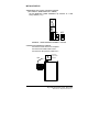
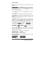
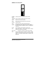
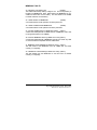
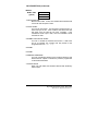
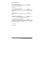
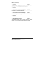
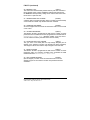
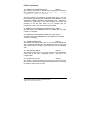
Instruction Bulletin EQ5300 QUICK START GUIDE DEVICENET WS2 WELD CONTROL MODULE P/N: 52045-062-50 SOFTWARE: APPL: J7 - INPUT POWER 115VAC, 50/60HZ, 45VA 4 - N/C 3 - GND 2 - NEUTRAL 1 - LINE P/S: 52045-018-50 REV ? PROCESSOR: 1400637 REV. F ANALOG BRD: 1400640 REV. ? Made in USA ! LABEL P/N 52045-069-01 C DANGER 1 2 4 8 16 32 ON 50006-524-15 June 2000 Revision 1.1 ! WARNING UNINTENTIONAL EQUIPMENT OPERATION The application of this equipment requires expertise in the design and programming of resistance welding control systems. Only persons with such expertise should be allowed to program or operate this product. Failure to observe this precaution can result in death, severe personal injury, or equipment damage. ! DANGER HAZARDOUS VOLTAGE Turn off power supplying this equipment before working inside. Electrical shock will result in death or severe personal injury. EQ5300 Quick Start Guide, DeviceNet WS2 50006-524-15 May 2000 Revision 1.1 INDEX INTRODUCTION.......................................................... 1 INITIAL STARTUP ....................................................... 2 STARTING THE PROCESS......................................... 3 USING THE KEYS ....................................................... 4 MENU STRUCTURE.................................................... 5 PREPARE FOR WELDING.......................................... 6 PROGRAMMING A SCHEDULE .................................. 8 MEMPACK................................................................. 10 I/O DESCRIPTION..................................................... 14 INPUTS...................................................................... 16 OUTPUTS.................................................................. 19 FAULTS ..................................................................... 21 EQ5300 Quick Start Guide, DeviceNet WS2 50006-524-15 May 2000 Revision 1.1 This page left blank. EQ5300 Quick Start Guide, DeviceNet WS2 50006-524-15 May 2000 Revision 1.1 INTRODUCTION This manual describes the basic operation of the EQ5300 PROC II Weld Control and the C1600 Data Entry Panel. It is intended to be used by trained personnel as a quick reference for programming and troubleshooting. For information on the Weld Control Module functions and specifications, refer to Bulletin No. 50006-524-02, EQ5300 Weld Control Module Functions and Specifications. WELD CONTROL MODEL NUMBER: 52046-100-68 SOFTWARE REVISION LEVEL: TIMER: 041800 and higher C1600: 1.07 and higher I/O BASE: 097N and higher I/O CONFIGURATION PLUG: PART NUMBER: 52046-286-65 (GM-NAO) I/O BASE CONFIGURATION: JP1: OFF JP2: OFF JP3: ON JP4: OFF For additional assistance, contact the Square D Troy Field Office at (248) 680-4444. P2QSWS2a.DOC EQ5300 Quick Start Guide, DeviceNet WS2 50006-524-15 May 2000 Revision 1.1 1 INITIAL STARTUP ADDRESSING THE WELD CONTROL MODULE (also called the TIMER MODULE or TIMER) Set the MEMPACK TIMER ADDRESS dip switches to a valid binary address (1-31). DATA LOAD SAVE DATA XFER POWER COM FAULT TIME R OK XFER BATT LOW 1 2 4 8 16 32 A D D R E S S ON OFF ON EXAMPLE: TIMER ADDRESS NUMBER 1 selected CONNECTING INTERFACE CABLES Connect the C1600 to the PL5 receptacle. Connect the DeviceNet cable to PL6. Connect the E-Stop 24VDC cable to PL7. PL5 2 Connectors PL7 - E-Stop 24VDC PL6 - DeviceNet EQ5300 Quick Start Guide, DeviceNet 50006-524-08 May 2000 Revision 1.1 STARTING THE PROCESS With the C1600 connected and weld control cabinet power on: 1. The REVISION screen is displayed for 5 seconds. 2. The C1600 will scan the TIMER network for all connected TIMERS. 3. The C1600 will upload the TIMER data from the TIMER with the lowest TIMER ADDRESS NUMBER on the network. If the same TIMER ADDRESS NUMBER is assigned to more than one TIMER, then that address will not be recognized by the C1600. 4. The MAIN MENU is displayed TIMER: _1 MAIN MENU RUN F STATUS-PROGRAM HELP REVISION DIAGNOSTICS Press the [WELD PROGRAM] key to jump to the PROGRAM MENU to modify SCHEDULES, FAULTS, STEPPERS, etc. Press the [STATUS] key to view STATUS data; LAST WELD information, STEPPERS, INPUTS, OUTPUTS, etc. Press the [FAULT STATUS] key to view current faults. If multiple TIMERS are connected to a network and a MENU screen is displayed, then other TIMERS may be accessed by pressing [HOME] to go to the TIMER NUMBER field, then entering the new TIMER NUMBER and pressing [ENTER]. The DEP will upload the new TIMER data automatically. EQ5300 Quick Start Guide, DeviceNet WS2 50006-524-15 May 2000 Revision 1.1 3 USING THE KEYS: Use the ↑↓ ← → keys to point the cursor at the desired item. Press [ENTER] to select. To change a value, press [ENTER] to display the edit window, use the ↑↓ ← → keys to select a field to change, type the new value or select an option with the arrow key and press [ENTER] to confirm and load the data into the TIMER. NOTE: The keyswitch must be in the PROGRAM position to make any changes. Use [ESCAPE] to cancel a change or go back to the previous menu. Select [HOME] to return the cursor to the first page of a screen. Press [HOME] again to go to the SCHEDULE, STEPPER, or TIMER number field at the top of the screen. The BLUE key is used to access functions keys that have blue backgrounds. First, press the BLUE key, a “↑” will be displayed in the upper right corner of the display to indicate the blue key has been pressed, then press the desired blue background function key. Select BLUE then [PAGE UP] or BLUE then [PAGE DOWN] to page up and down through multi-page screens. Select BLUE then [NEXT] or BLUE then[LAST] to go to the next or last SCHEDULE, STEPPER, or TIMER. Select the [FAULT RESET] key to reset the faults. If the fault still exists, (ex. - CONTROL STOP), the fault will not reset until the condition causing it is cleared. Pressing these hot keys will jump to the appropriate menu: [WELD PROGRAM] [STATUS] [STEPPER CONTROL] [FAULT STATUS] Pressing the BLUE key and then these blue background keys will jump to the appropriate menu: [DATA TRANSFER] [WELD/NO WELD] [TIMER SETUP] [SINGLE/REPEAT] 4 EQ5300 Quick Start Guide, DeviceNet 50006-524-08 May 2000 Revision 1.1 MENU STRUCTURE Status ⇒ [Status] Last Weld Stepper Faults ⇒ [Fault Status] Inputs Outputs Weld Bus Retry Logs Program ⇒ [Weld Program] Schedule Stepper ⇒ [Stepper Control] Timer Setup ⇒ [Timer Setup] Faults Turns Ratio Data Transfer ⇒ [Data Transfer] Last Weld Per Pulse Half Cycle Last Stepper Select Stepper Weld Log Fault Log Program Advance Reset Security Setup Process Tolerances Cond/Curr Tables Faults Retry Turns Ratio Setup Calculate Turns Ratio Schedule Types MemPack Printer Data Port ⇒ - Indicates hot key (jump to menu). Underlined items indicates blue background keys. EQ5300 Quick Start Guide, DeviceNet WS2 50006-524-15 May 2000 Revision 1.1 5 TO PREPARE FOR WELDING: Press the BLUE key and then [TIMER SETUP]. Program the TIMER SETUP to: Select SETUP. ↓TMR:01 TIMER SETUP PGM F ID:EQ5300 TIMER Weld/NoWeld Mode: WELD *** Single/Repeat Mode: SINGLE Process Checking Mode: OFF Nominal Volts: 480 Current Minimum: 20 Current Maximum: 9999 Contactor State: ON *** Saver Time: 3 Use Contactor in NoWeld: No CLEAR TIMER MEMORY EDIT TIMER ID *** - indicates items to change Press [ENTER] on each field to change its value. NOTES: PROCESS CHECKING MODE is for welding in production conditions. Leave OFF during startup. NOMINAL VOLTS is set at 480 VAC and cannot be changed. The weld control module will compensate for line voltage variations. Program the LINE VOLTAGE FAULT % field in PROGRAM / TIMER SETUP / PROCESS TOLERANCE to detect line voltage drops. The factory setting is 20%. The other two selections under the TIMER SETUP (PROCESS TOLERANCES and COND/CURR TABLES) are for extended process checking during production welding. Leave set at factory values during startup. 6 EQ5300 Quick Start Guide, DeviceNet 50006-524-08 May 2000 Revision 1.1 This page left blank. EQ5300 Quick Start Guide, DeviceNet WS2 50006-524-15 May 2000 Revision 1.1 7 PROGRAMMING A SCHEDULE NOTE: The C1600 keyswitch must be in the PROGRAM position to make any changes. Press [WELD PROGRAM], then select SCHEDULE; ↓TMR:01 SCHEDULE:_1 PGM F ID:EQ5300 SCHEDULE TYPE:FREE FORM 0 BEGIN 1 30~SQUEEZE(PRESSURE=10, STPR=0) 2 10~CCW @ 10.00KA 3 2~HOLD (0~OFF) 4 END TURNS RATIO: (16.0) EDIT DESCRIPTION COPY A SCHEDULE SWAP SCHEDULES SELECT SCHEDULE TYPE COPY TO ALL SCHEDULES Enter the desired schedule number in the SCHEDULE:_1← field and press [ENTER]. TO SELECT A SCHEDULE TYPE: arrow down ↓ to SELECT SCHEDULE TYPE and press [ENTER]. Use the ↑↓ ← → keys to select the desired schedule type (Single Pulse, Dual Pulse, etc., %I or CC (Constant Current)) then press [ENTER]. Select YES to confirm and press [ENTER]. TO INSERT AN INSTRUCTION: place the cursor on the line where the instruction will be inserted and press [INSERT]. Use the ↑↓ ← → keys to select the instruction to be inserted. Press [ENTER] to insert the instruction. TO DELETE AN INSTRUCTION: place the cursor on the line where the instruction to be deleted and press [DELETE]. Select YES to confirm and press [ENTER]. TO SELECT A DIFFERENT SCHEDULE: Select BLUE and [NEXT] for the next schedule or press [HOME] [HOME] ([HOME] twice) and enter the schedule number. 8 EQ5300 Quick Start Guide, DeviceNet 50006-524-08 May 2000 Revision 1.1 CCWELD - CONSTANT CURRENT: If a schedule is programmed with a CCWeld instruction, then a turns ratio must be programmed for that schedule in either the schedule or in the PROGRAM / TURNS RATIO menu. READY TO WELD After programming the TIMER SETUP and SCHEDULE as described in the previous sections, the weld control is ready to weld. SET INPUTS Use the controlling device outputs (ROBOT or PLC) to turn on the following weld control inputs (see I/O Description section, I/O LEDs): • • • • /CONTROL STOP (local) ENABLE CONTACTOR SAVER TRANSFORMER /OVERTEMP (local) WELD MODE ON Select a schedule by turning on the appropriate schedule select inputs, then turn on the INITIATE input to fire a weld. The INITIATE input must be turned off before turning on again to initiate another schedule. STARTUP REVIEW 1. 2. 3. 4. 5. 6. Connect C1600 DEP, DeviceNet and E-Stop 24VDC. Set MEMPACK TIMER ADDRESS dip switch. Program TIMER SETUP. Program SCHEDULE / TURNS RATIO. Set inputs. Turn on the schedule inputs to initiate a weld. EQ5300 Quick Start Guide, DeviceNet WS2 50006-524-15 May 2000 Revision 1.1 9 MEMPACK The MEMPACK provides non-volatile storage for all programmable data of the Weld Control Module (SCHEDULES, STEPPERS, SETUP, etc.) Status information (last weld amps, volts, gun counts, etc.) is not stored. OPERATION : To transfer data at the weld control cabinet: The SAVE operation takes approximately 2 minutes. The LOAD operation takes approximately 10 seconds. A blinking “M” will be displayed in the upper right hand corner of the C1600 display to indicate saving or loading. After a data transfer, the TIMER checks the data to make sure it was transferred completely and correctly. The MEMPACK data transfer can also be done from the DEP. Press the BLUE key and [DATA TRANSFER], then select MEMPACK, and then select the desired operation, LOAD TIMER FROM MEMPACK or SAVE TIMER TO MEMPACK. If a TIMER has a MEMORY LOST fault and a SAVE is performed, then the XFER LED will stay ON, indicating an INVALID TIMER DATA condition. The TIMER must be programmed and the MEMORY LOST fault cleared (press [FAULT RESET]) before being able to save to the MEMPACK. If a MEMPACK is used that is empty or has data that is incompatible with the TIMER data and a LOAD is performed, then the XFER LED will stay ON, indicating an INVALID MEMPACK DATA condition. A SAVE must be performed with the MEMPACK if the MEMPACK is empty or has incompatible data, or the TIMER must be replaced with a TIMER that is compatible with the MEMPACK data. 10 EQ5300 Quick Start Guide, DeviceNet 50006-524-08 May 2000 Revision 1.1 MEMPACK LED INDICATORS DATA LOAD SAVE DATA XFER POWER TIME R OK COM FAUL T XF ER BATT LOW A D D R 8 E 16 S 32 S 1 2 4 ON POWER (green) Indicates power is on to the weld control module. TIMER OK If OFF, indicates a defective weld control module. (green) Replace the weld control module. COM (yellow) Flickers when communications to the weld control module is active. XFER (yellow) Flashes when data is being transferred between the MEMPACK and the weld control module (TIMER). If ON solid, indicates a MEMPACK SAVE or a MEMPACK LOAD error. FAULT (red) If ON, indicates a fault condition is present in the weld control module. See the C1600 FAULT STATUS screen for the specific fault message. BATT LOW Indicates the voltage of the weld control module (red) memory backup battery is below the minimum voltage required to retain data when power is turned off to the weld control. The memory backup battery is located in the MEMPACK. EQ5300 Quick Start Guide, DeviceNet WS2 50006-524-15 May 2000 Revision 1.1 11 MEMPACK FAULTS 33 - BATTERY VOLTAGE LOW (ALERT) The TIMER data backup battery voltage is low. The backup battery is located in the MEMPACK. Note: Data saved in the MEMPACK is nonvolatile and does NOT use the battery. The data stored in the TIMER is volatile and does use the battery. 35 - TIMER SAVED TO MEMPACK (NONE) A successful DATA SAVE operation has been performed. 36 - TIMER LOADED FROM MEMPACK (NONE) A successful DATA LOAD operation has been performed. 37 - INVALID TIMER DATA [on MEMPACK SAVE] (FAULT) A SAVE was attempted with a TIMER that has a MEMORY LOST fault (no programmed data in the TIMER). 38 - INVALID MEMPACK DATA [on MEMPACK LOAD] (FAULT) A LOAD was attempted with a MEMPACK that did not contain any data or contained data incompatible with the TIMER data. 41- MEMPACK SAVE ERROR [on MEMPACK SAVE] (FAULT) The data saved to the MEMPACK from the TIMER was not saved correctly or completely. 42 - MEMPACK LOAD ERROR [on MEMPACK LOAD] (FAULT) The data loaded from the MEMPACK to the timer was not loaded correctly or completely. 12 EQ5300 Quick Start Guide, DeviceNet 50006-524-08 May 2000 Revision 1.1 This page left blank. EQ5300 Quick Start Guide, DeviceNet WS2 50006-524-15 May 2000 Revision 1.1 13 I/O DESCRIPTION Use the I/O module as a reference, the following is a description of the I/O bits: DEVICENET CONNECTOR LEDs I/O MODULE POWER DEVICENET STATUS I/O LEDs D-NET ADDRESS (MAC ID) POWER AND LOCAL I/O CONNECTOR TIMER I/O COMM CABLE WELD CONTROL MODULE P/N: 52045-062-50 SOFTWARE: APPL: J7 - INPUT POWER 115VAC, 50/60HZ, 45VA 4 - N/C 3 - GND 2 - NEUTRAL 1 - LINE P/S: 52045-018-50 REV ? PROCESSOR: 1400637 REV. F ANALOG BRD: 1400640 REV. ? Made in USA ! LABEL P/N 52045-069-01 C DANGER 1 2 4 8 16 32 ON I/O CONFIGURATION PLUG 14 EQ5300 Quick Start Guide, DeviceNet 50006-524-08 May 2000 Revision 1.1 I/O DESCRIPTION (continued) I/O LEDS TRANS OVERTEMP SHUNT TRIP ISO CONTACTOR SPARE CONTACTOR OPEN TIP DRESS REQ ALL STPRS RESET SCHD IN PRGRSS PROCESS CMPLT WELD MODE ON NO FAULT READ PRESSURE PRESSURE BIT 8 PRESSURE BIT 4 PRESSURE BIT 2 PRESSURE BIT 1 CAP CHNG REQ APPRCH CAP CHNG NO ALERT OUTPUTS (red) CONTROL STOP ISO CONT AUX SPARE SPARE BINARY SEL 32 BINARY SEL 16 BINARY SEL 8 BINARY SEL 4 BINARY SEL 2 BINARY SEL 1 CAPS CHANGED INITIATE WELD REQUEST PRESSURE SPARE SPARE EN CONT SAVER FAULT RESET WELD MODE ON INPUTS (yellow) CLOSED 50006-524-15 May 2000 Revision 1.1 OPEN ISO Contactor State Local I/O DeviceNet I/O Indicates I/O that will be ON to be ready to weld Turn ON to initiate a weld Isolation Contactor OFF ON ISO Aux Input ON ISO Cont Output OFF 15 EQ5300 Quick Start Guide, DeviceNet WS2 I/O DESCRIPTION (continued) INPUTS ROW 1 LEDs (yellow) 1 - - - - - - 18 1 WELD MODE ON Must be ON to weld. If OFF, then initiated weld schedules will not fire the SCR and pass current. 2 FAULT RESET Turn ON to reset faults. The NO FAULT output will turn on when this input is ON. If the condition that causes the fault still exists, then the fault will not reset. Example - if the /CONTROL STOP input is OFF, then the CONTROL STOP fault will not reset. 3 ENABLE CONTACTOR SAVER Turn ON to enable the Contactor Saver timer. If ON at the end of a schedule, the contactor will stay closed for the programmed time in Timer Setup. 4 SPARE 5 SPARE 6 REQUEST PRESSURE Turn ON with Binary Selects for the Pressure Bit binary and Read Pressure outputs to indicate the pressure programmed for the selected schedule. 7 INITIATE WELD When ON, will initiate the schedule selected with the Binary Select inputs. 16 EQ5300 Quick Start Guide, DeviceNet 50006-524-08 May 2000 Revision 1.1 I/O DESCRIPTION (continued) INPUTS (continued) ROW 1 LEDs (yellow) 1 - - - - - - 18 8 CAPS CHANGED When ON, resets the stepper counts and the tip dress counts on all steppers programmed ON to zero. Must be OFF for the stepper to count. 9-14 DATA 1, 2, 4, 8, 16, and 32 Binary schedule selects. Used for selecting weld schedules. EXAMPLES: Schedule # 1 3 15 60 1 X X X INPUTS (X = ON) 2 4 8 16 32 X X X X X X X X 15, 16 SPARE 17 ISO CONT AUX (Isolation Contactor Auxiliary contact) (Local input) Used to monitor the state of the isolation contactor Normally Closed Auxiliary contact. ON - contactor open. OFF - contactor closed. NOTE: If this input is OFF and the ISO CONTACTOR output is OFF (meaning the isolation contactor is closed when it should be open), then the weld control will shunt trip. 18 /CONTROL STOP (Local input) Must be ON to initiate a schedule. EQ5300 Quick Start Guide, DeviceNet WS2 50006-524-15 May 2000 Revision 1.1 17 I/O DESCRIPTION (continued) INPUTS (continued) (yellow) ROW 3 LEDs 12 17 18 18 TRANSFORMER /OVERTEMP (Local input) Must be ON to initiate a schedule. 18 EQ5300 Quick Start Guide, DeviceNet 50006-524-08 May 2000 Revision 1.1 I /O DESCRIPTION (continued) OUTPUTS ROW 2 LEDs (red) 1 - - - - - - 18 1 NO ALERT Turns ON if there are no alerts. Turns OFF if a fault condition that is programmed as ALERT is present. 2 APPROACHING CAP CHANGE Turns ON when the gun count has reached the last programmed step in the stepper or if the maximum number of tip dresses has been reached. 3 CAP CHANGE REQUEST Turns ON when any stepper programmed as ON reaches the end of the stepper (the end of the programmed steps.) 4 - 7 PRESSURE BIT 1, 2, 4, 8 Turns ON when the Request Pressure input is ON or during schedule execution. Reflects the programmed pressure for the selected schedule. 8 READ PRESSURE Turns ON when the Request Pressure input is on to indicate the binary pressure bit outputs are stable. 9 NO FAULT Turns ON if there are no faults. Turns OFF when a fault condition that is programmed as FAULT is present. 10 WELD MODE ON When ON, indicates the weld control is in the WELD mode. To be in Weld Mode, the Weld Mode On input must be ON and the timer must be programmed to WELD in Timer Setup. Turns OFF if in NO WELD. EQ5300 Quick Start Guide, DeviceNet WS2 50006-524-15 May 2000 Revision 1.1 19 I /O DESCRIPTION (continued) OUTPUTS (continued) ROW 2 LEDs (red) 1 - - - - - - 18 11 PROCESS COMPLETE Turns ON at the end of a weld schedule if there are not any errors programmed as FAULT active and the INITIATE WELD input is on. Goes OFF when INITIATE WELD input is turned off. 12 SCHEDULE IN PROGRESS Turns ON at the beginning of a weld schedule and turns OFF at the end of a weld schedule. 13 ALL STEPPERS RESET Turns ON if all the steppers that are programmed as ON are reset (weld counts are zero). 14 TIP DRESS REQUEST Turns ON when the stepper count reaches the beginning of the programmed TIP DRESS STEP if the number of TIP DRESSES is less than the programmed TIP DRESS LIMIT. 15 CONTACTOR OPEN Turns ON when the isolation contactor is open.. 16 SPARE 17 ISOLATION CONTACTOR (local output) Will turn ON the solid state relay which then closes the isolation contactor when a weld schedule is initiated. Wired internally to the weld control. 18 SHUNT TRIP (local output) Will turn ON and shunt trip the circuit breaker if the isolation contactor does not open or if current is detected when not welding. Wired internally to the weld control. 20 EQ5300 Quick Start Guide, DeviceNet 50006-524-08 May 2000 Revision 1.1 FAULTS Note: The following faults are listed as: FAULT CODE # - FAULT MESSAGE [NOTE] *(DEFAULT) Fault description. The asterisk (*) indicates that the fault is user programmable. CIRCUIT BREAKER MAGNETIC TRIP (NO FAULT CODE) If the power to the weld control is shut off during a weld, it is possible that the circuit breaker experienced a magnetic trip - which means the current exceeded the magnetic trip range setting. This fault is not detected or reported by the weld control. If this occurs, set the magnetic trip range to its maximum setting. The magnetic trip range is adjusted by moving the sliding bar located on the circuit breaker case, just below the circuit breaker ON / OFF switch. 1 - SHUNT TRIP BY CONTROL (FAULT) This message is displayed on power up after a shunt trip. The fault which caused the shunt trip will also be displayed. It was caused either by the ISO CONT AUX input not being ON when the ISOLATION CONTACTOR output was OFF (ISO DID NOT OPEN #46) or primary current flow was detected when the SCR was not being fired (UNEXPECTED PRIMARY CURRENT #49). 2 - Not used. 3 - PARITY ERROR *(FAULT) NOTE: Not used in WS2 The robot or PLC has selected a schedule with the incorrect number of schedule bits (Example: Schedule 3 was selected without parity bit). EQ5300 Quick Start Guide, DeviceNet WS2 50006-524-15 May 2000 Revision 1.1 21 FAULTS (continued) 4 - NO SCHEDULE SELECTED (FAULT) The robot or PLC has turned ON the INITIATE WELD input without turning on any Binary Select inputs. 5 - Not used. 6 - NO CURRENT PROGRAMMED (FAULT) A schedule was initiated that had no currents programmed in it (either %I or CCWeld). Check STATUS/LAST WELD to see what schedule was initiated. 7 - PILOT LOSS *(FAULT) The schedule select bits changed state during the first five cycles of initiate. 8 - NO WELD TIME PROGRAMMED (FAULT) A schedule was initiated with no weld time programmed. Check STATUS/LAST WELD to see what schedule was initiated. 9 - NO TURNS RATIO PROGRAMMED (FAULT) A schedule with a CCWeld instruction was initiated and the TURNS RATIO was not programmed for that schedule. A TURNS RATIO must be programmed either in the schedule or in PROGRAM/TURNS RATIO/TURNS RATIO SETUP. 10 - Not used. 11 - Not used. 22 EQ5300 Quick Start Guide, DeviceNet 50006-524-08 May 2000 Revision 1.1 FAULTS (continued) 12 - NO WELD *(ALERT) The WELD MODE ON input is OFF or the TIMER SETUP/ SETUP / WELD/NOWELD MODE field is programmed as NOWELD . 13 - Not used. 14 - NO STEPPER COUNTS PROGRAM[MED] (FAULT) A schedule was initiated which used a stepper that was turned on and did not have any count fields programmed. 15 - NO STEPPER BOOSTS PROGRAM[MED] (FAULT) A schedule was initiated which used a stepper that was turned on and did not have any boosts fields programmed. 16 - Not used. 17 - Not used. 18 - USER ABORTED SCHEDULE *(ALERT) The /CONTROL STOP input was turned OFF during schedule execution. This will stop firing the SCR and abort the schedule. EQ5300 Quick Start Guide, DeviceNet WS2 50006-524-15 May 2000 Revision 1.1 23 FAULTS (continued) 19 - ISO ENABLE INPUT OFF (FAULT) NOTE: Not used in WS2 The robot or PLC has not turned ON the ENABLE CONTACTOR SAVER input before initiating a weld. 20 - Not used. 21 - SCHEDULE DATA INTEGRITY *(FAULT) During the execution of a schedule, a schedule instruction was determined to be invalid. Either reprogram the schedule, or clear memory and LOAD the TIMER from the MEMPACK. 22 - INVALID I/O CONFIG (FAULT) The I/O CONFIGURATION PLUG (DB25 Pin on bottom of TIMER, see the I/O DESCRIPTION section) is either not plugged in, defective, or the timer software does not support it. Make sure the plug is firmly seated. 23 - Not used. 24 - WELD RANGE HIGH *(FAULT) The measured conduction/current for the last weld was higher than the corresponding value in the dynamic conduction current table by the programmed % in TIMER SETUP/PROCESS TOLERANCES. This indicates the last weld was different to the previous welds (most likely due to a shorted secondary cable or due to fitup, dirt on part, pressure, change in secondary, etc.) Verify weld current at the tips. If a short exists, the current read at the tips will be lower than reported by the weld control. 25 - TOOL TREND HIGH *(FAULT) If TIMER SETUP/PROCESS TOLERANCES/PROCESS CHECKING is turned ON, this indicates that the dynamic conduction current table (which indicates the present condition of the tool) is higher than the SetPoint conduction current table. A short condition may exist on the secondary cables. Verify the weld current at the tips. If a short exists, the current read at the tips will be lower than reported by the weld control. 24 EQ5300 Quick Start Guide, DeviceNet 50006-524-08 May 2000 Revision 1.1 FAULTS (continued) 26 - MEMORY LOST (FAULT) The weld control module battery backed memory was lost and reset to factory default values. Either a MEMORY CLEAR was performed or the MEMPACK backup battery voltage is low and the weld control was turned off for a period of time. 27 - APPROACHING CAP CHANGE *(ALERT) A stepper that is programmed ON is either in the last programmed step or the maximum number of tip dresses has been reached. 28 - STEPPERS ARE RESET *(ALERT) All of the steppers that are turned ON have been reset or have a weld count of zero. 29 - RETRIES EXCEEDED *(FAULT) The RETRY STATE is programmed as ON and the number of retries performed have exceeded the number programmed in the MAX field in PROGRAM/FAULTS/RETRY SETUP. (Example: If MAX: 10 of 100, then 11 or more retries have been performed in the last 100 welds.) 30 - 40 WELDS PAST CAP CHANGE (FAULT) The gun count is 40 welds past the Cap Change Request (end of stepper or the maximum number of tip dresses has been exceeded). The stepper must be reset and the caps changed to clear this fault. 31 - RETRY FAILURE *(FAULT) The RETRY STATE is programmed as ON and the number of retries performed during an executing schedule have exceeded the PER SCHEDULE limit in PROGRAM/FAULTS/ RETRY SETUP. 32 - CAP CHANGE REQUEST *(ALERT) (End of Stepper) The Gun count has reached the last count of a stepper program or the maximum number of tip dresses has been exceeded. EQ5300 Quick Start Guide, DeviceNet WS2 50006-524-15 May 2000 Revision 1.1 25 FAULTS (continued) 33 - BATTERY VOLTAGE LOW *(ALERT) The TIMER data backup battery voltage is low. The backup battery is located in the MEMPACK. Note: Data saved in the MEMPACK is nonvolatile and does NOT use the battery. The data stored in the TIMER is volatile and does use the battery. 34 - SCR OVER TEMP (FAULT) The temperature of the SCR chill plate has exceeded the set point of the thermostat. Other causes may be that the interface cable between the weld control module and the firing board is not connected or the plug from the chill plate mounted thermostat to the firing board is not connected. 35 - TIMER SAVED TO MEMPACK *(NONE) A successful DATA SAVE operation has been performed. 36 - TIMER LOADED FROM MEMPACK *(NONE) A successful DATA LOAD operation has been performed. 37 - INVALID TIMER DATA [on MEMPACK SAVE] (FAULT) A SAVE was attempted with a TIMER that has a MEMORY LOST fault (no programmed data in the TIMER). 38 - INVALID MEMPACK DATA [on MEMPACK LOAD] (FAULT) A LOAD was attempted with a MEMPACK that did not contain any data or contained data incompatible with the TIMER data. 39 - CC UNABLE TO COMPENSATE HIGH *(FAULT) The measured current for a constant current weld pulse was greater than the programmed value by the % in TIMER SETUP/ PROCESS TOLERANCES:CC UNABLE TO COMPENSATE %. This could be due to a shorted condition on the secondary cables, or the cables were changed without resetting the conduction/current table. 26 EQ5300 Quick Start Guide, DeviceNet 50006-524-08 May 2000 Revision 1.1 FAULTS (continued) 40 - UNABLE TO COMPENSATE LOW *(FAULT) The measured current for a constant current weld pulse was less than the programmed value by the % in TIMER SETUP / PROCESS TOLERANCES:CC UNABLE TO COMPENSATE %. The factory setting is 3% tolerance of programmed current. This can be changed by programming the UNABLE TO COMP RANGE % in the PROGRAM / TIMER / PROCESS TOLERANCE menu.. (Example: If 10.00kA was programmed in the weld schedule and 9.60kA was measured on the last weld, which is a 4% deviation from the programmed current, then this fault will be generated). 41- MEMPACK SAVE ERROR [on MEMPACK SAVE] (FAULT) The data saved to the MEMPACK from the TIMER was not saved correctly or completely. 42 - MEMPACK LOAD ERROR [on MEMPACK LOAD] (FAULT) The data loaded from the MEMPACK to the TIMER was not loaded correctly or completely. 43 - CURRENT IMBALANCE *(FAULT) The positive and negative half cycles of a weld cycle are imbalanced. This is caused by saturating the weld transformer from too high heats with multiple pulses or the gun is opening during a weld or a damaged SCR. 44 - SCR OVER CURRENT (FAULT) The average primary amps of a 1/2 cycle of weld current exceeded the current limit of the SCR - 2500Amps primary. This limit is not programmable 45 - ISO DID NOT CLOSE (FAULT) The isolation contactor auxiliary (ISO CONT AUX) input did not turn OFF when the ISOLATION CONTACTOR output turned ON, indicating the isolation contactor did not close. EQ5300 Quick Start Guide, DeviceNet WS2 50006-524-15 May 2000 Revision 1.1 27 FAULTS (continued) 46 - ISO DID NOT OPEN (FAULT) The isolation contactor auxiliary (ISO CONT AUX) input is OFF when it should be ON. In a control with an isolation contactor, the ISO CONT AUX input did not turn ON when the ISOLATION CONTACTOR output turned OFF, indicating the contactor did not open. A shunt trip will occur and this message will be displayed on power up. The isolation contactor must be open on power up or the control will continue to shunt trip. 47 - LINE SYNC LOST *(FAULT) When initiating a weld schedule, the weld control could not synchronize to the 480 VAC bus line frequency. 48 - TRANSFORMER OVERTEMP (FAULT) The local Transformer Overtemp input is OFF indicating that the temperature switch on the weld transformer has opened due to overheating. This input must be ON to weld. 49 - UNEXPECTED PRIMARY CURRENT (FAULT) Primary current flow was detected when the SCR was not being fired. A shunt trip will occur and this message will be displayed on power up. Either there is a primary 480 VAC short or a shorted SCR. 50 - Not used. 51 - STOPPED CONDUCTING (FAULT) The weld current stopped during welding. This may be caused by the gun opening before welding is complete. 28 EQ5300 Quick Start Guide, DeviceNet 50006-524-08 May 2000 Revision 1.1 FAULTS (continued) 52 - NO CURRENT > 2 CYCLES *(FAULT) [No current for greater than 2 cycles] Primary current was not detected for more than two cycles at the beginning of the weld. The weld gun was not closed or was wired to the wrong weld transformer. 53 - WELD OVER CURRENT *(FAULT) The weld current measured exceeded the CURRENT MAXIMUM value programmed in PROGRAM/TIMER SETUP/ SETUP or the CURRENT LIMITS instruction programmed in the schedule that was initiated. 54 - WELD UNDER CURRENT *(FAULT) The weld current measured was less than the CURRENT MINIMUM value programmed in PROGRAM/TIMER SETUP/ SETUP or the CURRENT LIMITS instruction programmed in the schedule that was initiated. 55 - %I UNABLE TO COMPENSATE *(FAULT) The measured conduction angle for a %I weld pulse was greater or less than the programmed value by the percent in TIMER SETUP/PROCESS TOLERANCES:%I UNABLE TO COMPENSATE %. The factory setting is 6% tolerance of programmed conduction angle. This can be changed by programming the %I UNABLE TO COMP RANGE % in the PROGRAM / TIMER / PROCESS TOLERANCE menu.. 56 - WELD RANGE LOW *(ALERT) The measured conduction/current for the last weld was lower than the corresponding value in the dynamic conduction current table by the programmed % in TIMER SETUP / PROCESS TOLERANCES:WELD RANGE%. This indicates the last weld was different to the previous welds (possibly due to a sudden breakdown in the secondary cables or due to fitup, dirt on part, pressure, change in secondary, etc.) EQ5300 Quick Start Guide, DeviceNet WS2 50006-524-15 May 2000 Revision 1.1 29 FAULTS (continued) 57 - TOOL TREND LOW If TIMER SETUP/PROCESS TOLERANCES/PROCESS CHECKING is turned ON, this indicates that the dynamic conduction current table (which indicates the present condition of the tool) is lower than the SetPoint conduction current table. This usually indicates that the secondary cables are breaking down. 58 - NOT USED 59 - VOLTAGE RANGE FAULT *(FAULT) The line voltage measured during a weld was not within the programmed LINE VOLTAGE FAULT % in PROGRAM/TIMER SETUP/PROCESS TOLERANCE. The default setting is 20% (±20% of 480V is 576V maximum and 384V minimum). 60 - NO COND/CURR SETPOINT TABLE (FAULT) The PROCESS CHECKING MODE was turned ON in PROGRAM /TIMER SETUP/PROCESS TOLERANCE and the SET POINT CONDUCTION / CURRENT table for the selected schedule was not set. Create a Set Point table in PROGRAM/TIMER SETUP /COND/CURR TABLES using the commands at the bottom of the table or turn the PROCESS CHECKING MODE OFF. 61 - CONDUCTION ANGLE LIMIT *(ALERT) The weld current has reached the maximum allowable conduction angle (172°). 62 - CONTROL STOP (FAULT) The robot or PLC does not have the /CONTROL STOP input turned ON. See the wiring diagram for complete circuit wiring. 63 - Not used. Note: The faults are listed as: FAULT CODE # - FAULT MESSAGE [NOTE] *(DEFAULT) Fault description. The asterisk (*) indicates that the fault is user programmable. 30 EQ5300 Quick Start Guide, DeviceNet 50006-524-08 May 2000 Revision 1.1 This page left blank. EQ5300 Quick Start Guide, DeviceNet WS2 50006-524-15 May 2000 Revision 1.1 31 2000 Square D Company. All rights reserved. This document may not be copied in whole or in part, or transferred to any other media, without the written permission of Square D Company. Electrical equipment should be serviced only by qualified electrical maintenance personnel, and this document should not be viewed as sufficient instruction for those who are not otherwise qualified to operate, service or maintain the equipment discussed. Although reasonable care has been taken to provide accurate and authoritative information in this document, no responsibility is assumed by Square D Company for any consequences arising out of the use of this material.