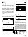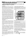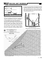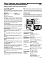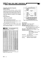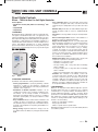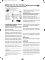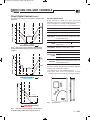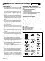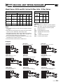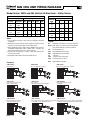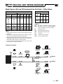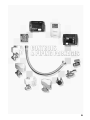
1
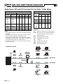
D1
FAN COIL UNIT CONTROLS
ECM/EPICTM FAN TECHNOLOGY®
• Significant energy savings (67% average
compared to PSC motors)
• Unique factory pre-set air volume capability
(+/- 5%)
• Pressure independent fan operation
• LED for visual indication of air volume
• Field adjustable fan air volume controller
• Remote fan air volume adjustment capability
from BAS
• Larger turndown ratios mean more flexibility
for tenant changes
Since 1985, equipment manufacturers have used ECM
motors in residential air conditioners and furnaces. These
motors have made it possible to achieve SEER ratings of 12
and higher. Until more recently though, they were only
manufactured in 120 and 240 VAC, which precluded their use
in commercial applications. Following two years of research
and development and the availability of a new 277 VAC
version, Nailor Industries was first to introduce the ECM motor
to the commercial HVAC market (Ashrae Journal, April 1997)
as an option for use in commercial fan powered terminal unit
applications.
WHAT IS AN ECM MOTOR?
The ECM (Electronically Commutated Motor) is an ultra high
efficiency programmable brushless DC motor utilizing a
permanent magnet motor and a built-in inverter. DC motors
are significantly more energy efficient than AC motors and
much easier to control. The major weakness of commercial
fan coil units until now, has been their low fan motor efficiency.
The widely used three speed fractional horsepower shaded
pole and permanent split capacitor (PSC) induction motor in
combination with a 3 speed switch or an electronic SCR
speed controller is extremely inefficient at typical operating
conditions. Due to acoustical considerations, the fan motor is
usually adjusted to operate at considerably less than full load
(where PSC motor efficiencies may be as high as 62%). PSC
motor efficiency drops off dramatically when turned down;
typically by at least half. Installed PSC motor efficiencies are
therefore typically in the range of only 12 – 45%. ECM motors
in contrast, maintain a high efficiency of 65 – 72% at all
speeds.
In addition to lower operating costs, EPIC Fan Technology®
allows Engineered Comfort to pre-set the fan airflow volume
at the factory.
The graphs below show the lower watts per cfm (translating
into lower operating costs as shown on the next page) and
wider operating ranges of commercial fan coils employing
EPIC Fan Technology® versus PSC induction motors.
FEATURES AND BENEFITS
Soft starts and slewed speed ramps are programmed into the
ECM motor eliminating stress transmitted to the mounting
bracket or hardware. They incorporate ball bearings providing
permanent lubrication unlike sleeve bearings requiring a
D2
8-20-07
minimum rpm operation for oiling. The wider operating range
of the ECM motor allows each model to actually replace two
models using induction motors. This feature alone provides
several benefits: a simpler product line to choose from, little or
no equipment changes necessary, more similar sized units on
the job, decreased spare parts inventory and increased
contractor flexibility. The low operating temperature of the
ECM motor (essentially ambient) requires very little energy to
offset the heat gain from the motor versus PSC motors which
run hot, typically around 90 – 150ºF (32 – 66ºC).
These features also extend the life of the ECM motor, which
are expected to provide an average 90,000 hours of operation
(versus 50,000 hours for a typical PSC motor). This translates
into about 10 years for a typical fan coil as opposed to 7 for
one using a PSC motor.
EPIC FAN TECHNOLOGY®
In addition to the above standard features, Nailor Industries
pioneered and developed EPIC Fan Technology® in order to
provide the following primary benefits – Maximized Energy
Savings, Variable Air Volume (VAV) control and factory pre-set
fan airflow.
Why and how do you pre-set fan airflow?
Pre-setting the fan airflow (cfm) has not been an issue with
fan coil manufacturers because these units were either on at
full load or off in normal operating conditions. With EPIC Fan
Technology®, the fan coils can now be run as a VAV device
with all of the requisite savings that VAV brings to other
commercial applications. (See control sequence for further
explanation.)
AC motors are not synchronous machines and the rpm, and
consequently the unit cfm, changes when static pressure
changes. The difficulty in pre-setting the fan lies in estimating
the motor workload required at the job site in actual working
conditions. The fan operated by an AC motor will not produce
the same volume of air as it did at the factory without the duct
work or loaded filter. Because there is no way to accurately
predict the downstream static pressure as it would exist at the
job site, it was impossible to pre-set the fan cfm. The ECM
motors are DC and inherently synchronous machines. The
motors are programmed to calculate the work they are doing
and then compare the work accomplished to the cfm
requirement. The integral microprocessor based controller
FAN COIL UNIT CONTROLS
1.00
0.80
AC INDUCTION
0.60
0.40
0.20
NAILOR EPIC
0.00
0
100
200
300
CFM
400
500
600
700
Comparison at 800 CFM for model series 39
0.80
0.70
The following graphs show the energy savings of units with
EPIC Fan Technology® compared to units with PSC motors.
The Engineered Comfort airflows are shown at relatively lower
set points (81%) due to a lower discharge air temperature
(See control sequence for further explanation).
0.60
AC INDUCTION
WATTS PER CFM
ENERGY SAVINGS
0.50
0.40
0.30
0.20
Comparison at 350 CFM for model series 39
0.50
Comparison at 600 CFM for model series 39
1.20
WATTS PER CFM
automatically adjusts the speed and torque in response to
system pressure changes and pressure independent constant
airflow operation is achieved without the need for an external
flow sensor feedback loop. Engineered Comfort fan coil units
incorporate our own custom EPIC fan controller, an electronic
PWM volume control device that allows adjustment of airflow
volume. Minimum and Maximum airflow can be pre-set at the
factory. It is field adjustable either manually using a
screwdriver and voltmeter locally at the fan coil or with the
Engineered Comfort thermostat and controller or remotely
using a 0 – 10 VDC analog output from a digital controller via
the BAS. A fan volume versus DC volts calibration chart is
provided. The importance of this feature is the energy that is
saved due to controlling the fan airflow as well as the large
reduction in noise generation. This also removes the
uncertainty of diffuser flow measurement with hoods.
Laboratory tests show the fan cfm to be accurate within +/- 5%
of the factory set point. This is a huge benefit to the owner, the
occupant, the controls contractor, and the mechanical
contractor.
0.10
0.00
AC INDUCTION
0.40
NAILOR EPIC
200
300
400
500
600
700
800
900
WATTS PER CFM
CFM
0.30
0.20
WHAT IS THE PAYBACK PERIOD WITH EPIC FAN
TECHNOLOGY® ?
NAILOR EPIC
0.10
0.00
150
200
250
CFM
300
350
400
Comparison at 400 CFM for model series 39
0.30
AC INDUCTION
WATTS PER CFM
0.25
0.20
0.15
NAILOR EPIC
0.10
0.05
0.00
150
200
250
300
CFM
350
400
450
500
The payback period varies. It depends on which unit you use,
where you set the airflow, how much you run the equipment
and what you are paying for electricity. The charts below are
calculated assuming 24/7 operation of the Nailor unit vs. 80%
run time on a competitive unit and $ 0.10 per kWh. If you run
the equipment longer in your building or if you pay more for
electricity, the payback will change proportionally. The charts
consider only operating costs of the fan, other savings at the
chiller and at the higher room set points can double the
savings cutting the payback in half. On tall buildings, reduced
riser sizes may offset the fan costs at the time of construction.
Typically, you can run anywhere from 3 to 11 Engineered
Comfort units for the same price as one of the competitions
making the payback period as short as 6 months to as long as
36 months.
HIGH SPEED COST TO RUN COST TO RUN NO. OF ENGINEERED COMFORT
AIR FLOW AC INDUCTION ENGINEERED
UNITS THAT CAN BE
(CFM)
FAN 1 YEAR
COMFORT
RUN FOR THE COST OF
FAN 1 YEAR
ONE COMPETITOR’S UNIT
350
$79.19
$15.77
5.02
400
$84.32
$17.04
4.95
600
$161.32
$21.81
7.40
800
$188.52
$16.51
11.42
5-21-07
D3
FAN COIL UNIT CONTROLS
Variable Air Volume EPIC Fan Technology® Fan Coil Operation with
Constant Discharge Air Temperature
THE SOLUTION
The attached sequence of operation (See Figure 2) and
psychometric chart (Figure 3), illustrate how the EPIC
control sequence utilizes variable air volume control, chilled
water valve modulation and constant discharge air
temperature to control a typical space using our unique
controls. Engineered Comfort has chosen 52ºF (11ºC) as
the optimum discharge air temperature for fan coil
operation.
By lowering the discharge air temperature slightly, the
humidity levels in the room can be lowered. See line C-D
on the attached psychometric chart. This causes the
occupants to feel more comfortable at a slightly higher
temperature. The room temperature required to maintain
acceptable comfort can be raised by as much as 4ºF
(2.5ºC). Most occupants will be more comfortable at the
increased temperature. This accomplishes five very
important results in addition to the energy and reheat
savings already provided by the ECM motor.
1. Lower relative humidity:
If the air volume and water to the coil are modulated to
maintain the discharge air temperature at all room
conditions as described in the EPIC control sequence,
room relative humidity levels decrease by 10 to 20%, and
there is less chance for wall sweating, which in turn lowers
the chances of mold growth. See line A-B vs. C-D on the
attached psychometric chart.
D4
8-20-07
70
rh
0%
10
68 O
FW
65
64
O
FW
et B
ulb
15
rh
%
50
et B
ulb
60
%
60
rh
10
55
50
Winter
Summer
30%
rh
45
40
35
30
25
20
10
5
60
65
70
75
80
OPERATIVE TEMPERATURE, OF
85
HUMIDITY PATIO, lb water vapor per 1000 lb dry air
As air moves across a cooling coil, the temperature of the
coil is normally below the dew point of the return air. This
causes the water in the air to condense on the coil surface
where it is gathered in a drain pan and disposed of through
drain lines. The air leaving a coil is typically about 55 to
60ºF. Since the temperature of the coil is usually below the
dew point of the entering air, water has been condensed
from the air and the air is very nearly saturated. This nearly
saturated air warms slightly as it moves through the duct to
the diffusers. By the time it exits into the room, it has risen
a degree or two in a typical system. It then mixes with the
room air and is again warmed, typically to about 74 – 78ºF
(23 – 26ºC). Both air temperature and water content are
increased in the room; however, relative humidity levels
decrease because the warmer air is capable of holding
more water. The percentage compared to saturated air at
the higher temperature has decreased. See line A-B on the
attached psychometric chart.
2. Higher comfort level temperature Setpoint:
The lowered relative humidity allows the occupant to reset
the room temperature higher by 1 – 4ºF (0.5 – 2.5ºC), while
maintaining acceptable comfort levels. This in turn saves
energy due to higher room set points. (See Figure 1 printed
from ASHRAE Handbook, Fundamentals 2005, Chapter 8,
page 8.12)
DEW-POINT TEMPERATURE, OF
THE PROBLEM
High humidity at part load conditions has always been a
problem with traditional fan coil unit operation and will
become a greater factor in the selection of equipment by
design engineers in the future. Too much humidity and
comfort zone temperatures decrease to the point that
occupants feel chilled or clammy. This may also create
favorable conditions for mold and mildew growth.
0
90
Figure 1: ASHRAE Summer and Winter Comfort Zones
(Acceptable ranges of operative temperature and humidity for people
in typical summer and winter clothing during primarily sedentary activity.)
3. Increased chiller efficiency:
If the air volume and water to the coil are modulated to
lower flow during part load conditions, fan energy and
pumping energy is saved by taking advantage of room to
room building diversity on both the water and air sides of
the unit. Additionally, this holds the water and air in contact
longer at the coil allowing greater heat transfer from the air
to the water. This increases the return water temperature to
the chiller and decreases the required pumping energy
while increasing the efficiency of the chiller operation.
Consequently, the pipe sizes needed for the risers and any
duct run outs may be reduced. These reductions may offset
any additional first cost of the equipment.
4. Lower airflow and reduced fan energy cost:
If the supply air temperature is lowered using the EPIC
control sequence, less air from the fan coil is needed to satisfy
the room demand. The reduction in airflow can be
calculated as follows:
CFM1 x ΔT1 = CFM2 x ΔT2
Where: CFM1 = Airflow and ΔT1 = EAT – LAT for Std. FCU
CFM2 = Airflow and ΔT2 = EAT – LAT for EPIC FCU
Therefore: CFM2 = CFM1 x (ΔT1)
ΔT2
FAN COIL UNIT CONTROLS
ΔT1 = 74 – 55 = 19 ΔT2 = 76 – 52 = 24
CFM2 = CFM1 x 0.79(19 )
24
Example 2:
ΔT1 = 78 – 55 = 23
ΔT2 = 79 – 52 = 27
23
CFM2 = CFM1 x 0.85( )
27
Average = 0.79 + 0.85 = 0.82
2
Average CFM2 = CFM1 x 0.82 (0.72 + 0.85)
2
Std. FCU (CFM1) = 300 400 600 800 1000 1200
EPIC FCU (CFM2) = 246 328 492 656 820 984
Table 1. Airflow Reduction Comparisons
Airflow can be lowered by approximately 18%, reducing the
fan energy consumption by 20 to 50%, depending on
setpoint, in addition to the input savings. (See Table 1.)
5. Lower humidity levels at part load conditions:
If the air volume is modulated to maintain the discharge air
temperature at all room conditions, the perceived comfort
level in the space stays constant and the noise levels
decrease. Also, the relative humidity is greatly decreased
when compared to what happens without modulated air at
part load conditions. See line ABʼ on the psychrometric
chart. Under part load conditions, without controlled
discharge air temperature, the relative humidity levels in
the space can rise to as much as 70% because of reduced
run time or lowered discharge air temperatures on the
dehumidifying equipment. This would cause the room set
points to be greatly reduced to satisfy occupant comfort,
which increases operating costs at part load conditions. At
these reduced set points, the room will feel clammy and
mold growth potential increases.
4ºF (2.2ºC)
PROPORTIONAL BAND
(ADJUSTABLE)
AIRFLOW INCREASE Example 1:
MAXIMUM
COOLING
MAXIMUM
HEATING
HEATER
ON/OFF
DEAD BAND
COOLING
VALVE
ON/OFF
G
TIN
ULA VE
O
M
VAL
ChW
SET POINT
ROOM TEMPERATURE INCREASE Figure 2. EPIC Fan Coil Unit Sequence of Operation
Chart 3: Psychrometric Chart
7-11-07
D5
FAN COIL UNIT CONTROLS
Analog Electronic Controls
Variable Air Volume • EPIC Fan Technology® • ECM Motor
FEATURES:
• Proportional + Integral control action provides precise flow
and temperature control.
• Standalone operation.
• Pressure Independent fan operation ensures airflow settings
remain constant.
• Factory calibrated controls simplify field installation and
eliminate field balancing.
• Less costly than digital controls with no software
programming requirement.
• Suitable for all types and sizes of residential and commercial
building applications.
• Modern ergonomic, easy to use thermostat with large LCD
display for live temperature read-out and nine function keys.
• Nine programmable functions for Set-point. Maximum
Airflow, Minimum (deadband) Airflow, ºF/ ºC mode, Two
Unoccupied Modes (off and deadband mode), Proportional
Band, Integration Time and Temperature Offset adjustment.
CEE-5201 Analog controller
CTE-5201W36 Analog LCD thermostat
Standard Control Sequence ACN • Cooling and 1 or 2 Stage Heating
Cooling Operation:
Off Unoccupied Mode:
On a call for cooling, the chilled water valve will begin to
modulate open. As the cooling demand increases, the valve
will continue to open until the discharge air temperature
reaches 52ºF (11ºC). On a continued call for cooling, the fan
will begin to modulate toward the maximum cooling fan airflow
as the chilled water valve continues to modulate open
maintaining a 52ºF (11ºC) discharge air temperature. This
process will continue until the fan reaches the cooling
maximum airflow.
The fan coil unit will be off. The heating set point will default to
50ºF (10ºC).
Deadband Unoccupied Mode:
52˚F DISCHARGE TEMP.
E
ED
W
DEAD BAND
20
LV
AT
ER
40
VA
MAX
60 HEATING
MAX
COOLING
ILL
On a call for heating, the fan will ramp up to the fan heating
setting and the first stage of heat will be energized. This may
be either an on/off hot water valve or a stage of electric heat.
Units with electric heat have an optional second stage
available. The fan may also be set to operate at a second
higher heating airflow setting. In the case of single stage
heating, it can be energized at either output. On a decrease in
heating demand, the sequence will reverse.
80
SET POINT
CENTERED IN
DEAD BAND
CH
Heating Operation:
100
1ST STAGE HEAT
With no demand in the space, there will be no call for heating
or cooling. The fan will be at minimum airflow. The chilled
water valve will be off. The hot water valve on the electric heat
will also be off.
AIRFLOW (% OF TOTAL CAPACITY)
Deadband Operation:
2ND STAGE HEAT
In the unoccupied mode the fan will run at the preset minimum
fan set point. The room temperature set point will default to
70ºF (21ºC), the heating set point will default to 60ºF and the
cooling set point will default to 80ºF (27ºC).
0
ROOM TEMPERATURE INCREASE
D6
8-20-07
FAN COIL UNIT CONTROLS
Analog Control Thermostat and Controller
LCD Analog Thermostat
MODEL: CTE-5201W36
The CTE-5201W36 single output with limits and PI function
thermostat is designed to be used with the CEE-5201 Fan Coil
Unit controller. The thermostat comes with the following factory
default settings:
Set Point (Default): 70°F (21.1ºC) F/C Mode: Degrees F
MAX: 100%
MIN: 20%
PROP: 4ºF (2.2ºC)
UNOCC Mode: OFF
INT: 30 Minutes
Operation and Adjustment
To change any one of these values, except the F/C Mode, first
push the button to display the value to be changed. Use the Up /
Down buttons to change the value. Then hold down the
corresponding button for approximately 10 seconds until the display
begins to flash. The new value has now been written into memory.
To change to degrees C mode simply press and hold the F/C
button down for 10 seconds until the display begins to flash. To
change back to degrees F repeat the procedure.
INT
As long as there is a difference between room temperature and set
point, the integral action will cause the output to integrate up or
down. The integral time is the time it takes the integral action to
repeat the effect of the proportional action. The integral time is
adjustable from 15 to 30 minutes. Setting the integral time to 0 will
disable the integral action.
Temperature Offset
By pressing both MIN and INT together it is possible to offset the
internal temperature sensor by +/- 2°F (-16.7 – -18.9°C). After
using the Up / Down buttons to change the offset both the MIN and
INT buttons must be held down together for 10 seconds until the
display begins to flash in order to write the new offset into memory
3 1/8" (79)
ROOM TEMP
SETPOINT
Set Point (Normal)
The set point range is 60 – 85°F (15.6 – 29.4°C). To change the
set point, push the SET POINT button to display the current value.
Use the Up / Down buttons to change the value. The display will
time out and revert back to displaying the room temperature and
the thermostat will control to the new set point.
5"
(127)
UP BUTTON
DOWN
BUTTON
SET
POINT
SET POINT
BUTTON
Set Point (Default)
If power is lost, when the unit is powered back up, the set point will
revert to the default value of 70°F (21.1 C). This default value can
be changed to any value in the set point range. This default set
point is also used in the dead band unoccupied mode.
MAX
This is the maximum value that the output can attain. It is
adjustable up to 100% (10 volts) and down to the MIN setting.
MIN
This is the min. value that the output can attain. It is adjustable
down to 0% (0 volts) and up to whatever the MAX is set for.
F/C Mode
The F/C button toggles the display between °F and °C. Room
temperature, set point, proportional band, dead band, and offset
will be displayed in the desired units.
UNOCC
Momentarily pressing this button will put the unit into the
unoccupied mode. It will stay in this mode until either the Set Point
or Up / Down buttons are pushed. There are two unoccupied
modes, OFF or DEADBAND.
OFF UNOCC Mode
The output voltage is forced to 0 volts (0%). A safety override will
bring the output up to 2 volts placing the unit in heating if the room
temperature falls below 50°F (10ºC). The output will return to 0
volts when the room temperature reaches 55°F (12.8ºC).
DEADBAND UNOCC Mode
In this mode the set point is set to 70°F (21.1ºC), the integral
action is disabled, and a dead band of +/- 10°F (5.5ºC) is set
around the set point. As long as the room temperature is within
the dead band the fan will run at MIN conditions.
PROP
The proportional band is the temperature band around the set
point over which the output will vary from MIN to MAX due to the
proportional action alone. The proportional band is adjustable from
2 – 6°F (1.1 – 3.3°C).
ACCESSORIES
HMO-1161W:
4" x 4" wallplate, White
HPO-0044:
Replacement allen screws
HSO-5013-50:
50' plenum cable w/conn.
HSO-5013-03:
3' plenum cable w/conn.
SET
POINT
MAX
F/C
PROG
MIN UNOCC INT
VIEW WITH COVER OPENED
Figure 1: Model CTE-5201W36 Analog Thermostat
Thermostat Specifications:
Supply Voltage:
Set Point Range:
14 -19 VDC
60 – 85°F (15.6 – 29.4°C)
(Power On Default: 70°F (21.1°C)
Temperature Sensor Type: Thermistor
Accuracy:
+/- 0.36ºF (0.2°C)
Display Degrees F or C: Selectable (Factory Setting: Degrees F)
Direct Acting Output: 0 – 10 VDC
MIN / MAX Limits:
Adjustable 0 – 100%
(Factory Settings: MIN=20, MAX=100)
Proportional Band: 2 – 6°F (1.1 – 3.3°C) (Factory Setting: 4°F)
Integration Time:
15 – 60 Minutes (0=OFF)
(Factory Setting: 30)
Unoccupied Setpoint Modes: OFF or Deadband
(Factory Setting: OFF)
OFF Mode:
Output Voltage = 0.0 Volts (Safety Override:
Output Cycles 0.0 Volts to 2.0 Volts. To
Maintain 50°F to 55°F (10 to 12.8ºC)
Deadband Mode:
Integral Action Disabled & Set Point.
Set to Default +/- 10°F (5.5ºC) Deadband.
Deadband Output Midway between Max &
Min.
Temperature Offset: Adjustable +/-2°F (1.1°C)
(Press MIN & INT together)
Operating Ambient: 34 – 125°F (1.1 – 51.6°C)
Shipping Ambient: -40 – 140°F (-40 – 60°C)
Humidity:
0 – 95% Non Condensing
Case Material:
White ABS.
UL Frame Class 94HB.
RJ-11 Female Connector.
PIN1 NC PIN2 COM PIN3 SUPPLY
PIN4 OUT PIN5 COM PIN6 NC
6-25-07
D7
FAN COIL UNIT CONTROLS
Analog Fan Coil Unit Controller
MODEL: CEE-5201
The Engineered Comfort CEE-5201 controller is mounted
inside the controls enclosure on the fan coil unit and is factory
wired. Engineered Comfort fan coil units with analog controls
provide extremely accurate variable air volume control. They
are factory calibrated for each unit permitting quick and easy
start-up with no field settings required, but may be simply and
easily field adjusted if necessary to suit changing
requirements.
Control Parameters:
•
•
•
•
Maximum fan cooling airflow.
Minimum fan cooling airflow.
Modulating Chilled Water Valve Actuator.
Stage 1 Heating with aux. fan airflow setting (on / off hot
water valve or one stage electric heat).
• Stage 2 Heating with aux. fan airflow setting (on / off hot
water valve or two stage electric heat).
Five potentiometers on the controller permit simple
adjustment of flow settings with a 0 – 10 Vdc voltmeter. Meter
taps are provided. A calibration chart is provided inside the
controls enclosure for each unit.
Figure 2. Typical Calibration Chart.
D8
6-25-07
Figure 1. CEE-5201 Analog Fan Coil Unit Controller.
Specifications:
Supply Voltage: 24 VAC +20/-15% 50/50Hz
Supply Power: 1 VA plus output loads
Discharge Temp Input: 10K OHM@25ºC, NTC 4.37% / ºC
Fan Output: Min. Adjustable 0 – 10 VDC
Stage 1 Max adjustable from Min. to 10 VDC
Stage 2 Max adjustable from stage 1 Max to 10VDC
Cooling Max adjustable from Min. to 10 VDC
CWV Output:
Max adjustable from 0 to 10 VDC
Heat Stage 1 & 2 Outputs: Triac outputs 10VA Max @ 24VAC
Thermostat connector: PIN 1 NC
PIN 2 DC COM
PIN 3 Supply Output 16 VDC +/-10% 10mA
PIN 4 T in 1-10 VDC 100 KOHM
PIN 5 DC COM
PIN 6 NC
Connections:
Plated screw terminals 14 to 22 AWG Cu
RJ-11 thermostat jack
Ambient Limits: Operating 0 to 120ºF (-18 to 49ºC)
Shipping -40 to 140ºF (-40 to 60ºC)
Mounting:
Open Board / Snaptrack supplied
FanCoilUnits-New_FanCoilUnits 9/29/14 9:06 AM Page D9
FAN COIL UNIT CONTROLS
Direct Digital Controls
®
EZstat – The All-In-One Fan Coil Digital Controller
Control Options:
• Variable Air Volume (VAV) EPIC Fan Technology® with
ECM
• 3-Speed ECM
• 3-Speed PSC
1.OVERVIEW:
Engineered Comfort’s new EZstat is the first commercial all-inone digital controller/thermostat for fan coil applications and
offers both simplicity and a competitive advantage for projects
that require Direct Digital Controller (DDC) fan coil application.
The EZstat is a fully digital and programmable standalone or
networkable device that combines a controller, multiple sensor
options, and BACnet networking into a single, integrated
space-mounted device which allows for energy efficiency and
superior user comfort through the use of proportional integral
(PI) control algorithms.
Fig. 1
EZstat
2. FEATURES & BENEFITS
The EZstat comes with the following standard features:
• Factory programmed No special programming, software
applications, or setup tools are required to configure and
commission an EZstat. EZstat comes fully programmed for
standard control sequences.
• Standalone or Network operation Installation can be
scalable from a single room to a network of multiple rooms.
The EZstat can be initially installed as standalone
thermostat and a MS/TP network connection to a building
automation system (BAS) can easily be added at a later
date as needed.
• Easy installation EZstat includes intuitive installation and
operation as well as a powerful set of additional features.
The attractive two-piece design has screw terminal blocks
mounted on the backplate for easy wiring and installation on
the wall or unit.
• Energy savings Significant reduction in energy costs can
be realized when the EZstat is packaged with the EPIC
ECM.
• Cost competitive EZstat can functionally replace many
competitors’ antiquated and bulky controller board and
separate two-piece temperature sensor products at a lower
cost.
• Network ready All models are native BACnet, Application
Specific Controllers ready to connect to a BACnet MS/TP
network.
• PI Control PI control algorithms ensure precise temperature
control.
• New or retrofit applications Ideal for new installations or
upgrades of older, less efficient thermostats.
• Bright, full-color display The full color LCD display (with
LED back lighting), animated icons, and five push buttons
make the EZstat intuitive and simple to configure and
operate. The display is easy to read across a room even in
bright sunlight. Color icons indicate cooling or heating,
occupied, unoccupied or local set back modes and fan
operations. Through the contextual menu-driven display, an
operator can change setpoints, configure available options
(e.g. easily choose between Fahrenheit or Celsius values),
and commission the installation.
• Multiple applications EZstat includes inputs, outputs, and
sequences of operation for the following functions:
- Modulating or 3-speed fan control
- Automatic or manual fan control
- Two-pipe heating and cooling with either modulating
valves or On/Off
- Four-pipe heating and cooling with either modulating
valves or On/Off
- Remote space temperature sensor (Optional accessory)
• Schedule The schedule in the EZstat controls the
occupancy mode. If the schedule is set to ON, the EZstat
uses the occupied set point as the active set point. If the
schedule is OFF, the unoccupied set point is used. The
schedule in the EZstat is a BACnet schedule object. If the
EZstat is connected to a BACnet network the schedule can
be set up with a BACnet operator workstation.
3. NETWORKING
EZstat is an integrated native BACnet Application Specific
Controller (ASC) that does not require the use of external
communication or occupancy modules. The EZstat meets or
exceeds BACnet® Application Specific Controller (ASC)
specifications in the ANSI/ ASHRAE BACnet Standard 135.
This enables the controller to integrate seamlessly with either
a future or existing BACnet BAS network allowing for the
network to do the following:
• Monitor all of the EZstat’s variables
• Assign setpoints values
• Initiate occupied and unoccupied modes.
Ultimately, leveraging the level of control and visibility inherent
to most BAS systems.
9-24-14
D9
FanCoilUnits-New_FanCoilUnits 9/29/14 9:06 AM Page D10
FAN COIL UNIT CONTROLS
Direct Digital Controls
(con’t)
Comunication with other BACnet
network devices and remote monitoring
BMS
integrated
temperature sensing
• Water
temperature
sensor
• Discharge air
temperature
• Remote
space
temperature
Three inputs for external
sensors
Readily supports
Engineered Comfort
control sequences
Quick (temporary
network access
through
computer
24 Volts
data port
AC power
requires a convertor
Fig. 2
Network setup
4. STANDARD CONTROL SEQUENCES – Engineered
Comfort’s most Popular Offerings
The EZstat can be factory or field configured for a number of
Engineered Comfort’s standard sequences. The sequence will
dictate whether the operation is 2 or 4 pipe and influence the
associated valve actuator’s performance and type, i.e. 0-10
VDC modulating and/or On/Off.
The EZstat may be used in digital applications using the EPIC
ECM along with monitoring the discharge air temperature
(DAT). The EPIC ECM is a variable speed DC motor that can
be adjusted to any speed required and capped at the
maximum CFM allowed by the unit it is installed in. A 0-10 VDC
signal is sent to the EPIC ECM which results in the control of
VAV operation. Alternatively, if a 3-speed ECM or PSC motor is
selected then the output would result in a constant air volume.
End users will benefit considerable energy savings in fan coil
units equipped with EPIC ECM, EZstat, and modulating water
valves or electric heat, when compared to units fitted with the
standard PSC motors. The reduction in energy consumption is
achieved by the ultra-high efficiency ECM and having the
EZstat modulate the motor speed to maintain the room
comfort level. The EZstat can be programmed up to a
maximum airflow for the cooling side and/or the maximum
airflow required for the heating side, as well as the minimum
CFM required for low energy consumption whilst the unit is in
deadband (more information on deadband can be found below).
More information on the EPIC ECM can be found herein under
the Fan Coil Unit Controls section of this catalog.
Exclusive Engineered Comfort control sequences can
accommodate all of the following Variable Air Volume (VAV)
applications:
• N501: Modulating Cooling/Modulating Heating with auto
Changeover
• N502: Modulating Cooling/Modulating Heating with Auxiliary
Staged Electric Heat
• N503: Modulating Cooling with Staged Electric Heat
• N505: Modulating Cooling/Modulating Heating
• N506: Modulating Cooling with Proportional Electric Heat
• N507: Modulating Cooling with On/Off Heat
D10
9-24-14
®
• N508: Proportional Electric Heat or Modulating Heating
(sequence driven by fan coil selection)
• N509: Staged Electric Heat or On/Off Hot Water Heat
(sequence driven by fan coil selection)
• N510: Modulating Cooling
EPIC ECM VAV Control for 4-pipe & 2-pipe Operation:
EPIC Discharge Air Temperature (DAT) Control
An EPIC ECM sequences include a Dischrge Air Temperature
(DAT) sensor. The sensor monitors the coil discharge
temperature on both the cooling and heating cycle.
The adjustable cooling discharge temperature is factory set to
52°F (11°C) and provides the humidity control under part load
conditions.
On heating, the adjustable discharge temperature is factory
set to 90°F (32°C) to provide improved occupant comfort and
meet ASHRAE standard 62.1 requirements.
The DAT is monitored by the control and will modulate the
valve according to the demand versus DAT set point.
Nailor recommends modulating chilled water valves, utilizing
our industry exclusive sequence design; with the superior
benefits of maintaining a constant discharge temperature.
Auto Changeover
A thermistor Type III water temperature sensor (WTS)
provides auto changeover for 2-pipe cooling/heating
operation. The sensor is attached to the incoming hydronic
pipe and changes thermostat mode from cooling to heating
based upon the water supply temperature.
Cooling Operation
On a call for cooling, the chilled water valve will begin to
modulate open. As the cooling demand increases, the valve
will continue to open until the discharge air temperature
reaches 52°F (11°C). Simultaneously, the fan will modulate
from minimum airflow to maximum airflow to achieve room set
point. Upon a decrease in cooling demand, the sequence will
reverse.
Deadband Operation
With no demand in the space, there will be no call for heating
or cooling. The fan will be at a deadband set minimum airflow.
The water valve will be off and the electric heat relay will also
be off, if applicable.
Heating Operation
On a call for heating, the hot water valve will begin to modulate
open. The valve will continue to open until the discharge air
temperature reaches 90°F (32°C). Simultaneously, the fan will
modulate from minimum airflow to maximum airflow to achieve
room set point. Upon a decrease in heating demand, the
sequence will reverse.
Auxiliary 2-pipe Electric Heat (Seasonal)
On a call for heat with chilled water in the pipe, the water valve
closes and the electric heat turns on. The fan will step up to
the stage 1 fan heating setting and the first stage of electric
heat will be energized to achieve room set point. Units with
electric heat may have an optional second stage available. On
a continued call for heat, the fan will step up to the stage 2 fan
heating setting and the second stage of heat will be energized
to achieve room set point. On a decrease in heating demand,
the sequence will reverse. On a call for heat with hot water in
the pipe, the electric heat is locked out.
FanCoilUnits-New_FanCoilUnits 9/29/14 9:06 AM Page D11
FAN COIL UNIT CONTROLS
Direct Digital Controls
(con’t)
The following are examples of two Engineered Comfort control
sequences:
52 °F DISCHARGE TEMP.
RF
E
AT
TW
MIN.
DEAD BAND
W
LO
20
Design Indoor use only
Weight Approx. 6 oz. (170 grams)
24 VAC (-15%, +20%), 50 – 60 Hz, 12 VA,
Supply Voltage non supervised (all circuits, including supply voltage,
are power limited circuits)
2°F
-2 °F
HEATING
SETPOINT
COOLING
SETPOINT
Fig. 3
EPIC Control Sequence Example: VAV Modulating
Cooling and Modulating Heating (4-pipe and 2-pipe hydronic
operation)
52 °F DISCHARGE TEMP.
100
80
MAX.
COOLING
LO
WA
TE
RF
ED
ILL
20
MIN.
DEAD BAND
CH
STAGE 2 HEAT/FAN
40
STAGE 1 HEAT/FAN
W
MAX.
HEATING
0
2 °F
-2 1.7
°F °F
0.7
°F
HEATING
SETPOINT
0– 12 volts DC with internal 10 k
Inputs pull-up resistors
+2 °F
ROOM TEMPERATURE INCREASE
AIRFLOW (% OF TOTAL CAPACITY)
Product specification includes a one piece wall mounted
temperature sensor and controller design; two piece designs
are not acceptable for controlling a room temperature.
Following specifications are subject to change without notice.
Wiring Class 2 only
0
60
5. Product Specifications
Material White flame-retardant plastic
CH
ILL
ED
WA
TE
R
40
MAX.
COOLING
FL
OW
90 °F DISCHARGE TEMP.
60
MAX.
HEATING
HO
AIRFLOW (% OF TOTAL CAPACITY)
100
80
®
COOLING
SETPOINT
+2 F
˚
SPST, 24 volts, 1 amp AC or DC
Relay Outputs Maximum for all relay outputs is 3 amps
Analog Outputs Short protected 10 mA 0 – 12 VDC
Operating 32 to 140 °F (0 to 49 °C)
Environmental Shipping - 40 to 160 °F (- 40 to 71 °C)
Limits
Humidity 0 to 95% RH, non condensing
UL 916 Energy Management Equipment
Regulatory FCC Class A, Part 15, Subpart B and complies with
Canadian ICES-003 Class A
This device complies with part 15 of the FCC Rules. Operation
is subject to the following two conditions:
1. This device may not cause harmful interference
2. This device must accept any interference received,
including interference that may cause undesired operation.
ROOM TEMPERATURE INCREASE
3 1/2" (89)
1 1/8" (29)
COOLING MODE
90 °F DISCHARGE TEMP.
80
60
MAX.
HEATING
40
HO
5 1/8"
(130)
MIN.
DEAD BAND
RF
E
AT
TW
20
W
LO
AIRFLOW (% OF TOTAL CAPACITY)
100
0
2 ˚F
-2 °F
HEATING
SETPOINT
Fig. 5
Unit dimensions
ROOM TEMPERATURE DECREASE
HEATING MODE
Fig. 4
EPIC Control Sequence Example: VAV Modulating
Cooling/Modulating Heating w/Aux Staged Electric Heat
9-24-14
D11
FAN COIL UNIT PIPING PACKAGES
GENERAL NOTES:
Basic System Types and Application:
1. Nailor only recommends chilled water valve control for Nailor
All types may use a 2-way or 3-way motorized control
valve
D12
9-10-07
2-Pipe System (One Valve Package)
A) Hydronic Cooling Only
B) Hydronic Heating Only
C) Hydronic Cooling and Heating (Aquastat required)
D) Hydronic Cooling with Total Electric Heat
E) Hydronic Cooling and Heating with Auxiliary Electric
Heat (Aquastat required)
4-Pipe System (Two Valve Packages)
A) Hydronic Cooling and Heating
Legend:
BV
Ball Valves (2). Memory stop where required.
BVPT Ball Valves (2) with Pressure/Temperature (P/T)
Port. Memory stop where required.
FC
Fixed Flow Control
FCC Fixed Cartridge Flow Control
AFS Adjustable Flow Circuit Setter
YS
Y Strainer
YSB Y Strainer w/hose bib valve
PTO P/T Ports (other location)
BPV Bypass Balancing Valve
COIL
BALL VALVE (BV)
FLEX HOSE
COIL
UNION (UN)
2-WAY MOTORIZED
CONTROL VALVE
BALL VALVE WITH
P/T PORT (BVPT)
M
FIXED FLOW
CONTROL (FC)
FLOW
1/2" 2511 GPM
3-WAY MOTORIZED
CONTROL VALVE
Y-STRAINER (YS)
BYPASS
BALANCING
VALVE
M
ADJUSTABLE FLOW
CIRCUIT SETTER (AFS)
Y-STRAINER WITH
HOSE BIB (YSB)
AQUASTAT
A
TER
VE
T SET
VAL
CUI
CIR ANCE
T
SSE
BAL
L GO
BEL
Digital and Analog VAV control sequences where a constant
discharge temperature is maintained and humidity is therefore
controlled. Modulating cooling valve control with fixed fan
speed electric controls can increase relative humidity in the
space at part load conditions. Modulating heat valve control
may result in low leaving air temperatures while the valves
reduce flow as setpoint is approached. Nailor does not
recommend their use with standard controls for either
application.
2. All 39 Series Hi-Rise Units include two flexible stainless steel
briefed hoses and full port ball isolation valves per coil. This
hose/valve combination provides a “union” type connection to
allow coil removal. Hi-Rise Units require a Nailor supplied
piping package which is factory assembled, installed and
wired.
3. 35F and 37F Horizontal Units with Nailor Digital and Analog
VAV Controls require a Nailor supplied piping package. This
package (less optional ball valve) is factory assembled,
installed and wired in a full protective enclosure with access
door. Ball valves when selected as part of the package ship
loose for field connection.
4. All standard piping packages and components described in
this catalog are for chilled and hot water applications. They
may be also used with up to 50% ethylene and propylene
glycol solutions.
5. Control valve actuators are removable and may be serviced or
replaced without removal of the valve body. All control valves
are piped on the return side of the coil (3-way control valves
are mixing).
6. 2-position (spring return) chilled and hot water valve / actuators
are piped normally closed to the coil as standard. For hot water
coils, control valves are available normally open as an option.
This must be stated clearly on schedule/order.
7. All ball isolation valves on the return line are furnished with an
adjustable memory stop feature (when no other flow control
device is selected) and may be used as a balancing valve.
8. Pressure/Temperature (P/T) ports when selected are supplied
on the ball valves as standard. If it is required that P/T ports be
located to monitor the pressure and temperature directly
across the coil only, select PTO (other location) option.
9. Automatic fixed flow controls (FC, FCC) are available in the
following flow (GPM) ratings. Individual coil GPM requirements
must be specified on schedule/order.
1/2" (13) valve: 0.5 to 4.0 GPM in 0.5 GPM increments. 5 to 9
GPM in 1 GPM increments.
3/4" (19) valve: 3.0 to 4.0 GPM in 0.5 GPM increments. 5 to 12
GPM in 1 GPM increments.
10. 2-pipe system cooling and heating auto changeover systems
using a 2-way control valve include a 1/4" (6.3) bleed line to
assure proper changeover thermostat (Aquastat) operation.
11. The valve package piping and component details in the catalog
are for standard valves and components. Performance ratings
such as Cv, max. close-off pressure, operating temperature
and pressure are shown in component specifications.
Suitability for use must be based on individual application
requirements determined by others. Nailor assumes no
responsibility for selection and/or application of valve package
and components.
FAN COIL UNIT PIPING PACKAGES
Model Series: 39VH and 39L Vertical Hi-Rise Units • 2-Way Valves
2-Way Chilled / Hot Water Valve
Basic Package Code
2-Position
Actuator
202
203
210
211
212
213
214
Modulating
Actuator
402
403
410
411
412
413
414
Options
Components
BV
BVPT
FC
FCC
Options
Package
Code
01
02
03
04
05
AFS
•
•
•
•
•
•
•
•
•
•
•
Components
YS
YSB
PTO
•
•
•
•
•
•
•
Legend:
•
Notes:
1. Select a Basic Package for each valve and an Options Package
if required.
2. Nailor Electric Controls (PSC motor) require a 2-position actuator
selection for both chilled water and hot water valves.
3. Nailor Digital and Analog VAV Controls (ECM motor) require a
modulating chilled water valve actuator and a 2-position hot
water valve actuator selection for 4-pipe systems.
4. A 1/4" (6.3) bleed line and Aquastat is furnished on 2-pipe cooling
and heating auto changeover systems.
5. All Vertical Hi-Rise Units include two flexible hoses.
BV
Ball Valves (2). Memory stop where required.
BVPT
Ball Valves (2) with Pressure/Temperature
(P/T) Ports. Memory stop where required.
FC
Fixed Flow Control
FCC
Fixed Cartridge Flow Control
AFS
Adjustable Flow Circuit Setter
YS
Y Strainer
YSB
Y Strainer w/hose bib valve
PTO
P/T Ports (other location)
Examples:
CODE: 202/402
BALL VALVES
CODE: 203/403
BALL VALVES WITH P/T PORTS
M
CODE: 210/410
BALL VALVES, FIXED FLOW CONTROL
M
M
FLOW
1/2" 2511 GPM
COIL
COIL
CODE: 211/411
BALL VALVES WITH P/T PORTS,
FIXED FLOW CONTROL
COIL
CODE: 214/414
BALL VALVES,
ADJUSTABLE FLOW CIRCUIT SETTER
M
M
M
ER
SETT VE
UIT
VAL
CIRC ANCE
SET
BAL
L GOS
BEL
FLOW
1/2" 2511 GPM
COIL
COIL
COIL
CODE: 203/403-02
BALL VALVES WITH P/T PORTS,
Y-STRAINER W/HOSE BIB
CODE: 211/411-01
BALL VALVES WITH P/T PORTS,
FIXED FLOW CONTROL, Y-STRAINER
M
B
COIL
CODE: 203/403-01
BALL VALVES WITH P/T PORTS,
Y-STRAINER
CODE: 211/411-02
BALL VALVES WITH P/T PORTS, FIXED FOW
CONTROL, Y-STRAINER W/HOSE BIB
M
A
B
COIL
M
A
FLOW
B
1/2" 2511 GPM
A
FLOW
1/2" 2511 GPM
COIL
6-26-07
D13
FAN COIL UNIT PIPING PACKAGES
Model Series: 39VH and 39L Vertical Hi-Rise Units • 3-Way Valves
3-Way Chilled / Hot Water Valve
Basic Package Code
2-Position
Actuator
302
303
310
311
312
313
314
Modulating
Actuator
502
503
510
511
512
513
514
Options
Components
BV
BVPT
FC
FCC
Options
Package
Code
01
02
03
04
05
06
07
08
09
10
AFS
•
•
•
•
•
•
•
•
•
•
•
•
Notes:
1. Select a Basic Package for each valve and an Options Package
if required.
2. Nailor Electric Controls (PSC motor) require a 2-position actuator
selection for both chilled water and hot water valves.
3. Nailor Digital and Analog VAV Controls (ECM motor) require a
modulating chilled water valve actuator and a 2-position hot
water valve actuator selection for 4-pipe systems.
4. An Aquastat is furnished on 2-pipe cooling and heating auto
changeover systems.
5. All Vertical Hi-Rise Units include two flexible hoses.
YSB
PTO
BPV
•
•
•
•
•
•
•
•
•
•
•
•
•
•
•
•
•
•
BV
Ball Valves (2). Memory stop where required.
BVPT
Ball Valves (2) with Pressure/Temperature
(P/T) Ports. Memory stop where required.
FC
Fixed Flow Control
FCC
Fixed Cartridge Flow Control
AFS
Adjustable Flow Circuit Setter
YS
Y Strainer
YSB
Y Strainer w/hose bib valve
PTO
P/T Ports (other location)
BPV
Bypass Balancing Valve
CODE: 303/503
BALL VALVES WITH P/T PORTS
M
YS
Legend:
Examples:
CODE: 302/502
BALL VALVES
Components
CODE: 310/510
BALL VALVES, FIXED FLOW CONTROL
M
M
FLOW
1/2" 2511 GPM
COIL
COIL
CODE: 311/511
BALL VALVES WITH P/T PORTS,
FIXED FLOW CONTROL
COIL
CODE: 314/514
BALL VALVES,
ADJUSTABLE FLOW CIRCUIT SETTER
M
CODE: 303/503-01
BALL VALVES WITH P/T PORTS,
Y-STRAINER
M
M
ER
SETT VE
UIT
VAL
CIRC ANCE
SET
BAL
L GOS
BEL
FLOW
1/2" 2511 GPM
COIL
COIL
COIL
CODE: 303/503-06
BALL VALVES WITH P/T PORTS,
BYPASS BALANCING VALVE
CODE: 311/511-07
CODE: 311/511-08
BALL VALVES W/ P/T PORTS, FIXED FLOW CONTROL, BALL VALVES WITH P/T PORTS, FIXED FLOW CONTROL,
Y-STRAINER, BYPASS BALANCING VALVE
Y-STRAINER W/HOSE BIB, BYPASS BALANCING VALVE
M
M
M
FLOW
FLOW
1/2" 2511 GPM
1/2" 2511 GPM
COIL
D14
COIL
6-26-07
COIL
FAN COIL UNIT PIPING PACKAGES
Model Series: 35F and 37F Horizontal Fan Coil Units • 2-Way Valves
2-Way Chilled / Hot Water Valve
Basic Package Code
2-Position
Actuator
201
202
203
204
205
206
210
211
212
213
214
Modulating
Actuator
401
402
403
404
405
406
410
411
412
413
414
Options
Components
BV
BVPT
FC
FCC
Options
Package
Code
01
02
03
04
05
AFS
•
•
•
•
Components
YS
YSB
PTO
•
•
•
•
•
•
•
•
•
•
•
•
•
•
Legend:
•
•
•
•
Notes:
1. Select a Basic Package for each valve and an Options Package
if required.
2. Nailor Electric Controls (PSC motor) require a 2-position actuator
selection for both chilled water and hot water valves.
3. Nailor Digital and Analog VAV Controls (ECM motor) require a
modulating chilled water valve actuator and a 2-position hot
water valve actuator selection for 4-pipe systems.
4. A 1/4" (6.3) bleed line and Aquastat is furnished on 2-pipe cooling
and heating auto changeover systems.
BV
Ball Valves (2). Memory stop where required.
BVPT
Ball Valves (2) with Pressure/Temperature
(P/T) Ports. Memory stop where required.
FC
Fixed Flow Control
FCC
Fixed Cartridge Flow Control
AFS
Adjustable Flow Circuit Setter
YS
Y Strainer
YSB
Y Strainer w/hose bib valve
PTO
P/T Ports (other location)
Component Location:
TER
VE
T SET
VAL
CUI
CIR ANCE
T
SSE
BAL
L GO
BEL
2-WAY VALVE
WITH 2-POSITION
OR MODUATING
ACTUATOR
UNION (UN)
MANUAL
AIR
VENT
ADJUSTABLE
FLOW CIRCUIT
SETTER (AFS)
SWAGE
P/T PORT
OPTION (PTO)
H
F
BALL VALVE WITH P/T PORT
(BVPT) AND MEMORY STOP
FLOW
1/2" 2511 GPM
M
FIXED FLOW
CONTROL (FC)
BALL VALVE (BV)
WITH MEMORY STOP
D
B
Return
C
A
Supply
Y-STRAINER (YS)
BALL VALVE (BV)
Y-STRAINER
W/ HOSE BIB VALVE
(YSB)
BALL VALVE
WITH P/T PORT (BVPT)
Aquastat BLEED LINE
(AS REQUIRED)
COIL
A
G
E
SWAGE
P/T PORT
OPTION (PTO)
Aquastat
COIL
UNION (UN)
6-26-07
D15
FAN COIL UNIT PIPING PACKAGES
Model Series: 35F and 37F Horizontal Fan Coil Units • 3-Way Valves
3-Way Chilled / Hot Water Valve
Basic Package Code
2-Position
Actuator
301
302
303
304
305
306
310
311
312
313
314
Modulating
Actuator
501
502
503
504
505
506
510
511
512
513
514
Options
Components
BV
BVPT
FC
FCC
Options
Package
Code
01
02
03
04
05
06
07
08
09
10
AFS
•
•
•
•
•
•
•
•
•
•
•
•
•
•
•
Components
YS
YSB
PTO
BPV
•
•
•
•
•
•
•
•
•
•
•
•
•
•
•
•
•
•
Legend:
Notes:
BV
Ball Valves (2). Memory stop where required.
1. Select a Basic Package for each valve and an Options Package
if required.
2. Nailor Electric Controls (PSC motor) require a 2-position actuator
selection for both chilled water and hot water valves.
3. Nailor Digital and Analog VAV Controls (ECM motor) require a
modulating chilled water valve actuator and a 2-position hot
water valve actuator selection for 4-pipe systems.
4. An Aquastat is furnished on 2-pipe cooling and heating auto
changeover systems.
BVPT
Ball Valves (2) with Pressure/Temperature
(P/T) Ports. Memory stop where required.
FC
Fixed Flow Control
FCC
Fixed Cartridge Flow Control
AFS
Adjustable Flow Circuit Setter
YS
Y Strainer
YSB
Y Strainer w/hose bib valve
PTO
P/T Ports (other location)
BPV
Bypass Balancing Valve
Component Location:
TER
VE
T SET
VAL
CUI
CIR ANCE
T
SSE
BAL
L GO
BEL
3-WAY VALVE
WITH 2-POSITION
OR MODUATING
ACTUATOR
UNION (UN)
MANUAL
AIR
VENT
ADJUSTABLE
FLOW CIRCUIT
SETTER (AFS)
SWAGE
P/T PORT
OPTION (PTO)
H
F
OPTIONAL BYPASS
BALANCE VALVE
COIL
G
E
SWAGE
P/T PORT
OPTION (PTO)
BALL VALVE WITH P/T PORT
(BVPT) AND MEMORY STOP
FLOW
1/2" 2511 GPM
M
FIXED FLOW
CONTROL (FC)
BALL VALVE (BV)
WITH MEMORY STOP
D
B
Return
C
A
Supply
Y-STRAINER (YS)
BALL VALVE (BV)
Y-STRAINER
W/ HOSE BIB VALVE
(YSB)
BALL VALVE
WITH P/T PORT (BVPT)
A
Aquastat
COIL
UNION (UN)
D16
6-26-07
FAN COIL UNIT PIPING PACKAGES
Components and Specifications
Engineered Comfort Vertical Hi-Rise fan coil units are supplied
as standard with a factory supplied and installed valve
package for the main cooling coil and optional heating coil.
This assures all components are compatible with the
application and install with the physical restrictions of the
cabinet for ease of maintainance and service.
Engineered Comfort Horizontal fan coil units have standard
valve packages available as a factory installed or “ship loose”
Manual Ball Valve with Memory Stop
(BV)
Ball valves, also known as end valves,
allow the unit to be cut off for servicing
purposes. They are often used for
water balancing. These full port ball
valves have a compact handle that
rotates 90 degrees. The return side
valve is supplied with an adjustable
memory stop position lever to limit
travel of the on/off handle where required. This allows the ball
valve to be closed and returned to the balance setting position
without re-testing the system.
Nominal size: 1/2" or 3/4"
Body material: Forged brass
Ball: Chrome plated brass
Ball seal: Teflon
AB
A
Figure 1. 2-way Valve
(Normally open to coil flow)
Shaft seals: Viton O-Rings
Temp. rating: 325ºF max.
Pressure rating: 600 psi max.
Cv: 17 (1/2"), 40 (3/4")
2-Way, 2-Position Control Valve /
Actuator
All valves are piped on the return
side of the coil. Figure 3 shows the
valves in the open position or full
flow position. The valve spring
provides the necessary force to
hold the stem in the raised or
Normally Open (NO) position.
In the open position, water can flow
through the coil to heat or cool the
space. In the closed position, water
cannot flow. Actuators are 2position spring return operation.
The Normally Open (NO) or
Normally Closed (NC) valve
position (relative to water flow
through the coil) on power failure is
determined by the actuator model
selection. NO / NC action must be
compatible with the thermostat /
control package selection.
Actuator are available for line and
24 Vac low voltage applications.
Nominal size: 1/2" or 3/4"
Body material: Brass
Pressure rating: 125 psi max.
Temperature rating: 230ºF max.
Max. close off pressure: 44 psi
Cv: 2.5 (1/2"), 4.1 (3/4")
Actuator power consumption:
10 VA max.
option for field connection.
Valve packages consist of a variety of components and
selection is dependent upon the application. The following
section provides a detailed description of each of the
components. Photos are for general representation purposes
only. Vendors and models are subject to change without
notice.
Manual Ball Valve
with
P/T
Port
(BVPT)
Same use as BV
above except in
addition, the supply
and return side valve
includes a Pressure /
Temperature
(PT)
Port to allow testing
of water pressure,
different pressure or water temperature across the coil/valve
package assembly. The return side valve is supplied with an
adjustable memory stop where required for balancing.
Nominal size: 1/2" or 3/4"
Body material: Forged brass
Ball: Chrome plated brass
Ball seal: Teflon
Shaft seals: Viton O-Rings
Temp. rating: 325ºF max.
Pressure rating: 600 psi
Cv: 21 (1/2"), 42 (3/4")
3-Way, 2-Position Control Valve /
Actuator
3-Way valves are piped on the
return side of the coil as mixing
valves. In the open position, water
can flow through the coil to heat or
cool the space and the bypass port
is closed. (Flow is A to AB). In the
closed position, water cannot flow
through the water coil and is
diverted to flow through the
bypass line (Flow is B to AB)
maintaining full flow through the
bypass port. Actuators are
2-position spring return operation.
The NO / NC valve position on
power failure (relative to water flow
through the coil) is determined by
the actuator model selection and
must be compatible with the
thermostat / control package
selection.
Actuator are available for line and
24 Vac low voltage applications.
Nominal size: 1/2" or 3/4"
Body material: Brass
Pressure rating: 125 psi max.
Temperature rating: 230ºF max.
Max. close off pressure: 44 psi
Cv: 2.5 (1/2"), 4.1 (3/4")
Actuator power consumption:
10 VA max.
COM
A
AB
NC
B
Figure 2. 3-way Valve
(Normally open to coil flow)
9-10-07
D17
FAN COIL UNIT PIPING PACKAGES
2-Way Modulating
Valve / Actuator
Control
3-Way Modulating Control Valve
/ Actuator
Valve operation is described
above. Actuators use a 0 – 10
Vdc control signal, are fail-inplace design (non-spring return)
and provide proportional control
from minimum to maximum
water flow through the coil in
response to room demand from
a
compatible
controller.
Modulating valves are standard
on Nailor analog and digital
EPIC control package chilled
water valves.
Valve operation is described
above. Actuators use a 0 – 10 Vdc
analog control signal, are fail-inplace design (non-spring return)
and provide proportional control
minimum to maximum water flow
through the coil in response to
room demand from a compatible
controller. Modulating valves are
standard on Nailor analog and
digital EPIC control package chilled
water valves.
Actuator are 3-wire 24 Vac only
(2.5 VA).
Flexible Hose Kits (FH)
Fixed Flow Control (FC)
See full description elsewhere in
catalog. Standard on all Vertical
Hi-Rise Units.
A
pressure
compensated
automatic fixed flow device,
designed to limit the flow GPM
through the coil. This inline version
comes with a fixed flow rate in a
tamperproof housing. Desired
GPM must be specified.
Nominal size: 1/2" or 3/4"
Flow Range: 0.5 – 20.0 GPM
options
Body material: Copper
Pressure differential range: 2 – 80
psid
Temperature rating: 220ºF max.
Cv: Variable with inlet pressure
Core: Fabric reinforced EPDM
Braid: Stainless Steel
Fiting: Brass OT58
Ferrule: Stainless Steel
Gasket Seal: Fiber / EDPM
Cv: 3.5 (1/2"), 12.8 (3/4")
D18
7-11-07
Actuator are 3-wire 24 Vac only
(2.5 VA).
Cartridge Fixed Flow Control
(FCC)
Adjustable Flow Circuit Setter
(AFS)
A
pressure
compensated
automatic fixed flow device,
designed to limit the flow through
the coil. This model features a
changeable flow cartridge. Y-design
allows changing the flow rate
without dismantling the piping.
Nominal size: 1/2" or 3/4"
Body material: Forged brass
Flow Range: 0.5 – 8.0 GPM options
Pressure differential range:
2
– 80 psid
Temperature rating: 220ºF max.
Cv: Variable with inlet pressure
A pressure dependent ball type flow
control device, precisely calibrated
for use as a presettable balance
valve, variable orifice flow meter and
positive shut-off service valve.
Furnished
with
a
calibrated
nameplate and memory stop
indicator and built in P/T ports.
Nominal size: 1/2" or 3/4"
Pressure rating: 200 psig max.
Temp. rating: 250ºF max.
Body material: Brass
Ball: Brass
Cv: Variable
FAN COIL UNIT PIPING PACKAGES
Y Strainer (YS)
An inline fitting designed to allow
water to flow through a built in
removable screen to filter debris or
contaminates. With the water
system isolated, the plug can be
removed from the blowdown leg
and the captured debris removed
from the screen.
Nominal size: 1/2" or 3/4"
Pressure rating: 600 psig max.
Body: Forged brass
Temperature rating: 325ºF max.
Screen: 20 mesh, 304 stainless
steel
Cv: 5.5 (1/2"), 9.0 (3/4")
(Valve with the clean filter)
Y Strainer with Hose Bib
Valve (YSB)
A Y-Strainer with the
addition of a manual ball
valve installed on the
blowdown leg. The valve
has a standard 3/4" garden
hose connection and cap to
allow fluid to be piped to a
container.
Unions (UN)
Bypass Balancing Valve (BPV)
An optional fitting used to provide a
mechanical connection between the coil
and valve package on horizontal fan coil
units (not available on Hi-Rise units). Can
be connected and disconnected without
the need to cut piping or unsolder a joint.
A ball valve used to balance the water
flow through the bypass circuit of a 3way control valve. Manual adjustment
is required. No calibration is provided
at the valve.
Aquastat (AQ)
The Aquastat, also called
a
summer-winter
changeover switch or
aqua thermostat, is a
switch
designed
to
automatically change a
room thermostat from
heating to cooling and
back in a 2-pipe system to
be used for both heating and cooling. The switch is attached to
the incoming water pipe with a spring and senses water
temperature.
Switch action: Bimetal snap acting disc SPDT
Setpoint: 75ºF (24ºC) approx, fixed
Differential: 15ºF (8ºC) fixed
Switch rating: 120 Vac, 5.8 FLA, 34.8 LRA (inductive) Pilot duty 125 VA.
Wiring: White (common). Black-White close on temp. rise (82ºF).
Blue-white close on temp. drop (67ºF)
Optional
Pressure
/
Temperature
Test
Ports
Location (PTO)
P/T ports allow testing of water
pressure, differential pressure and
water
temperature
without
interrupting
the
waterside
operation of the fan coil unit. P/T
Ports when specified are located
on the ball valves as standard
(see BVPT). When P/T ports are
required in another location, such
as directly across the coil, this
PTO option should be specified.
Nominal size: 1/4"
Connection: 1/4" MNPT
Body material: Brass
Pressure rating: 1000 psig max.
Temp. rating: 325ºF max.
7-11-07
D19
FAN COIL UNITS
Electric Heating Coils • Application Guidelines
When considering the capacity and airflow for the heater,
discharge air temperature can be an important factor.
Rooms use different types of diffusers, and they are
intended to perform different functions. Slots that blend the
air at the glass and set up air curtains within the room, must
be able to blow the air very low in the room. Hot air will be
too buoyant to be effective in this case. Discharge air
temperatures for this application should be in the 85 – 90°F
(29 – 32°C) maximum range.
Diffusers in the center of the room blend their discharge air
as it crosses the ceiling. Discharge air temperatures in this
application can be as high as 105°F (41°C) and still be
effective. However, if the return air grilles are in the
discharge air pattern, the warm air will be returned to the
plenum before it heats the room. Again, the air temperature
needs to be blended down to an acceptable temperature
that can be forced down into the occupied space by the
time the air gets to the walls. Discharging warm air into the
room at temperatures above 105°F (41°C) usually will set
up stratification layers and will not keep the occupants
warm if there is a ceiling return because only the top 12" –
24" (300 – 600 mm) of the room will be heated.
The maximum approved discharge air temperature for any
Engineered Comfort Fan Coil Units with supplemental heat
is 120°F (49°C). No heater should be applied to exceed this
temperature.
The desired heating airflow for the room can then be
calculated using the following equation:
cfm =
ΔT (Discharge air temp – Inlet air temp.) °F
Assuming 70°F (21°C) supply air temperature to the heater,
the room airflow can be selected directly from the chart.
Start at the left at the design kW. Move horizontally to the
desired discharge air temperature. Then, move vertically
down to the cfm at the bottom of the chart.
The kW can be selected directly from the chart. Start at the
bottom with the design cfm into the room. Move vertically
up to the line that represents the desired discharge air
temperature. Then, move left to the kW.
The discharge air temperature can also be selected directly
from the chart. Start at the bottom with the design cfm into
the room. Move to the left side of the chart and find the
design kW. Move horizontally and vertically into the chart
until the lines intersect. The intersection will be the desired
discharge air temperature. Interpolation between the
curves is linear.
Heater Selection Chart
Assuming 70°F inlet air temperature at heater.
170
D20
6-6-07
115°F
50
110°F
160
45
150
140
Electric Heater Selection
105°F
40
130
100°F
120
35
110
95°F
30
100
MBH
To properly select an electric heater, three things must be
determined: the heat requirement for the room, the entering
air temperature and the desired discharge air temperature.
The heat requirement for the room is the sum of the heat
loss calculation and the amount of heat required to raise
the entering air temperature to the desired room
temperature. Usually, the second item is small compared to
the first for fan coil units in a return air plenum. MBH can be
converted to kW by using the chart or by calculation. There
are 3413 BTUʼs in 1 kW. If using the chart, find the MBH on
the left scale, then move horizontally to the right and read
kW.
Next, the desired discharge air temperature should be
ascertained. This will depend on the type of diffusers that
are in the room.
kW x 3160
90
80
70
kW
Discharge Air Temperature
25
90°F
20
85°F
60
50
15
80°F
40
30
20
10
0
10
5
0
0
500
1000
1500 2000 2500
AIRFLOW, CFM
3000
3500
4000
Diagonal lines are constant output temperature.