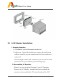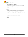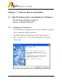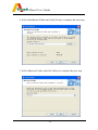
1
ATouch User Guide
4 Wire / 5 Wire Resistive Touchscreen
Table of Contents
Chapter 1
Introduction ……………………………….
1.1
4 Wire Resistive Touch Screen ……………..…
1.1.1 4 Wire Resistive Touch Sensor ……………..…
1.1.2 4 Wire Resistive Controller ………..…………
1.2
3
3
3
4
5 Wire Resistive Touch Screen …………………..
4
1.2.1 5 Wire Resistive Touch Sensor …………………..
4
1.2.2 5 Wire Resistive Controller ………………….. .. .
5
1.3
Software Drivers …………………….. .. .. .. .. .. ..
5
1.4
Agency Approvals ………………………………… 5
1.5
Warranty …………………………………………
Chapter 2
5
Touchscreen Installation …………………. 6
2.1
CRT Monitor Installation ………………………..… 6
2.2
LCD Monitor Installation …...………………..…… 8
Chapter 3
3.1
Software Driver Installation …….………. 11
RS-232 Software Driver Installation for Windows
11
3.1.1 Installing the Touch Driver ……………………..…. 11
3.1.2 Uninstalling the Touch Driver …….…………..…… 14
3.1.3 Calibration ………………………………………….. 15
3.1.4 Control Center ………………………………….…..
3.2
17
USB Software Driver Installation for Windows ..… 25
1
ATouch User Guide
3.3
Linux Driver…….…………………………………… 31
Chapter 4
Troubleshooting ……………………….….
Chapter 5
Appendix
Contact ……………………………………. 33
Jumper Definition ……………………….. 34
2
32
ATouch User Guide
Chapter 1 Introduction
Thank you for choosing ATouch Touch Screen. It’s our great honor to
present the most advanced touch screen to you. This User Guide will lead you
through the installation of 4 Wire/ 5 Wire e Resistive. Please follow the
instruction and enjoy the technologies with ATouch Touch Screen.
1.1
4 Wire Resistive Touch Screen
1.1.1 4 Wire Resistive Touch Sensor
ATouch’s 4 Wire Resistive Touch Screen is of the most extensive
application. It is capable of working by any kind of physical touches, such as
finger, gloved hand (any kind of gloves). It is liquid resistance and
contamination proof and even works in bad environment such as foul, dirt,
greasiness. 4 Wire Resistive touch screen is also noted for its high accuracy
and reliability with low cost advantage. Therefore it becomes the most popular
touch screen in applications, especially in handset device uses.
ATouch 4 Wire Resistive Touch Screen supports RS-232 & USB
interfaces for :
LCD Display : 6..4” – 19”
CRT Flat Display : 17”-21”
4 Wire Resistive Touchscreen Features:
- Low cost
- Finger, gloved hand and stylus activation
- High accuracy and sensitivity
3
ATouch User Guide
- High durability and reliability
- Contaminant proof and liquid resistance.
1.1.2 4 Wire Resistive Controller
ATocuh’s 4 Wire Controllers provide the drive signals for the touchscreen,
convert analog signals into digital touch coordinates, and send coordinates to
the host.
ATouch provides RS-232 and USB interfaces for 4 Wire Controllers.
RS-232 controllers are designed two kinds of serial connectors for customers
to choose different kinds of serial cables.
1.2 5 Wire Resistive Touch Screen
1.2.1 5 Wire Resistive Touch Sensor
ATouch’s 5 Wire Resistive Touch Screen is a most extensively various
application. It works by any kind of physical touch, not only by fingers,
gloved hands (any kind of gloves). It is liquid resistance and contamination
proof. It works even in bad environment, such as foul, dirt, greasiness.
ATouch 5 Wire products are the most reliable available, and have the
expected life performance for more than 35 million touches in one location
without failure.
ATouch 5 Wire Resistive Touch Screen support RS-232 and USB interface
for :
LCD Displays: 10.4” – 19”
CRT Flat Displays: 17”-21”
4
ATouch User Guide
1.2.2 5 Wire Resistive Controller
ATocuh’s 5 Wire Controllers provide drive signals for the touchscreen,
convert analog signals into digital touch coordinates, and send coordinates to
the host.
ATouch provides RS-232 and USB interfaces for 5 Wire Controllers.
RS-232 controllers are designed two kinds of serial connectors for customers
to choose different kinds of serial cables.
1.3 Software Drivers
Drivers supporting operating system are as follow :
Windows : 95/98/Me/2000/XP/NT
Linux : Red Hat 9.0, Mandrake 9.1
1.4 Agency Approvals
FCC
CE
1.5 Warranty
4 Wire Resistive Touch Sensor: 1 years
4 Wire Resistive Controller (RS-232 or USB) : 1 years
5 Wire Resistive Touch Sensor: 5 years
5 Wire Resistive Controller (RS-232 or USB) : 5 years
5
ATouch User Guide
Chapter 2
Touchscreen Installation
2.1 CRT Monitor Installation
CRT monitor installation process as following steps :
1. Incoming inspection
x CRT monitor : please check if the monitor works well.
x Touchscreen : please unpack the touchscreen, connect your
touchscreen with the controller on your PC and test if the
touchscreen works well.
x After testing the monitor and touchscreen, you can start to install
touchscreen into your monitor by the following steps.
2. Disassembling CRT monitor
x Remove the back side plastic housing of your CRT monitor.
x Discharge the CRT tube from the front bezel (usually there are 4
screws on the 4 corners need to be released).
x Check if the electronic board needs to be removed or not.
x Verify the fit position on the CRT tube for the touchscreen.
x After verifying the position, you can attach the touch sensor onto
the CRT. You can use the double side high tack adhesive tape (as
3M) to attach the touch sensor onto the CRT display
x After this process, check the space between the touch
sensor and the front bezel. If the space is not enough, you may
need to add rubber spacers between the touch sensor and the front
bezel ( the 4 corners on which the CRT and the front bezel is
6
ATouch User Guide
screwed ).
x Installing Touchscreen Controller
Connect all cables / connectors in right places and fix the
controller at the monitor chassis.
x Power Supply
If you use internal power supply +5VDC, connect the power
cord (from touchscreen RS-232 controller) to the CRT monitor
electronic board +5VDC.
If the external power supply is used, the +5VDC will be
supplied from the keyboard through the RS-232 cable provided by
ATouch.
x Fixing Cables
Cables should be fixed well and not movable.
x After above processes, test if the touch monitor works normally.
3. Reassembling CRT Monitor
After the installation of the touchscreen, reassemble the CRT
monitor back side plastic housing and test if the function of the
touch monitor works well.
4. Sealing
Sealing should be even around the front bezel. The material is
special sponges from ATouch. The adhesive side of the sponge is
stuck on the front bezel, and the special plastic side on the touch
sensor.
Or use the material manufactured by VOLTEK.
(Suggest from VOLTEK : 2A/2E//4A/4E black flame retardant
material)
7
ATouch User Guide
2.2 LCD Monitor Installation
1. Incoming inspection
x LCD monitor : check if the monitor works well.
x Touchscreen : Unpack the touchscreen, connect the touchscreen
with the controller on your computer and test if the touchscreen
works well.
x After testing the monitor and touchscreen, you can start to install
touchscreen into your monitor by the following steps.
2. Disassembling LCD monitor
x Remove the rear side plastic housing of your LCD monitor.
x Remove the LCD display from the front bezel and kindly be
attention to disassemble the LCD control board and the OSD
8
ATouch User Guide
board.
x Verify the fit position on the LCD display for the touchscreen.
x After verifying the position, attach the touchscreen sensor on the
LCD. Use the double side high tack adhesive tape (as 3M) to
attach touchscreen sensor on the LCD display.
x After this process, check the space between the touchscreen sensor
and the front bezel if there is any gape ( You can use the special
sponge provided by ATouch to fulfill it).
x Installing Touchscreen Controller
Connect all cables / connectors in the right places and fix the
controller at the right position on the monitor rear side metal or
plastic case.
x Power supply
If you use internal power supply +5VDC, connect the power
cord (from touchscreen RS-232 controller ) to the LCD control
board +5VDC.
If the external power supply is used, the +5VDC will be
supplied from the keyboard through the RS-232 cable provided
by ATouch.
x Fixing Cables
Cables should be fixed well and not movable. Please note that
cables do not get close to the inverter or the power supply.
x After above processes, test if the touch monitor works well.
3. Reassembling LCD Monitor
x After the processes mentioned above, reassemble the rear side
9
ATouch User Guide
plastic housing of the LCD monitor.
x Seal the monitor if you need to seal it before you reassemble the
front bezel of the LCD monitor.
x Test if the touch monitor function works well.
4. Sealing
Sealing should be even around the front bezel. The material is
the special sponges from ATouch. The adhesive side of the sponge
is stuck on the front bezel, and the special plastic side on the touch
sensor.
Or use the material manufactured by VOLTEK
(Suggest from VOLTEK : 2A/2E//4A/4E black flame retardant
material).
10
ATouch User Guide
Chapter 3 Software Driver Installation
3.1 RS-232 Software Driver Installation for Windows
The following installation is applied to
Windows 95/98/Me/2000/XP/NT
3.1.1
Installing the Touch Driver
1. Launch Windows operating system, and exit all Windows programs
before continuing with the installation.
2. Insert the ATouch utility diskette into the floppy disk drive.
3. Run “A Touch-2.0.exe”. The following dialog box will appear.
Click [Next].
11
ATouch User Guide
4. Select Installation Folder and click [Next] to continue the next step.
5. Select Shortcut Folder and click [Next] to continue the next step.
12
ATouch User Guide
6. Now the ATouch touchscreen setting is completed. Please check the
installation setting. If you accept the setting, please click [Next] to
install the driver.
7. After the driver installation, a dialog box will launch for you to
choose the serial port which your touch monitor is currently
connected to.
8. Select the serial port and click [Finish] to start the four-point
calibration.
9. Touch each center of the point sequentially. Four calibration points
in total.
13
ATouch User Guide
10. The installation completes.
3.1.2
Uninstalling the Touch Driver
There are two ways to remove the touch driver.
1. Use the Add/Remove Programs feature in the Control Panel.
x Open the Control Panel
x Click Start, hover over Settings, click Control Panel
x Double-click the Add/Remove Programs icon
x Choose the A Touch 2.0 item.
x Click the Change/Remove button.
x Click the Yes button
x The ATouch driver will be removed. No computer restart is
required.
2. Use Shortcut Folder icon in the Start Menu.
x Click Start, hover over Programs, choose A Touch folder and
click Uninstall.
14
ATouch User Guide
3.1.3 Calibration
Calibration ensures that the cursor appears at the position of touch.
ATouch uses a four-point calibration sequence that will accept
touchscreens with any orientation of the X or Y axis.
Once calibrated, the touchscreen will be ready to use automatically
each time the system is restarted.
y Options to Launch
The Calibration Program may be launched by three different ways.
x Double-click the ATouch icon on the desktop. Choose Calibrate
tab and click the Calibration button.
x Click Start, hover over Programs, choose ATouch folder and click
Calibration.
x Click right mouse button on the ATouch icon in the Windows task
bar at the bottom right of the display and click the Calibration.
15
ATouch User Guide
y Running the Calibration Program
1. When you run the calibration program using one of the options
above, touch the center of the four targets as they appear
sequentially.
2. When you release your finger on each point, you will hear a beep.
3. After the calibration completes, you can
- press ENTER or touch the touchscreen to save and exit.
- press SPACE to calibrate again.
- press ESC to discard the result and exit.
16
ATouch User Guide
3.1.4
Control Center
The control Center application allows configuration of the driver to suit
the application programs, and present system and diagnostic
information to the user.
Each of the five tabs in the Control Center is described below.
1. Running the Control Center
The Control Center may be launched by four different ways to
adjust the properties.
x Double-click the ATouch icon on the desktop.
x Click Start, hover over Programs, choose ATouch folder and click
Control Center.
x Click the ATouch icon in the Windows task bar at the bottom right
of the display.
x Click right mouse button on the ATouch icon in the Windows task
bar at the bottom right of the display and click Show Control
Center.
17
ATouch User Guide
2. Calibrate
x The Calibrate tab is displayed when the Control Center is launched.
x Serial port is changeable. Choose the right serial port with which
the touchscreen connects, and click Apply button.
x Click the Calibration button to calibrate.
18
ATouch User Guide
3. Settings
y
Mouse Action
There are three combinations for this function.
x Drag Mode and Click on touch
Click on touch sends, immediately upon touch, a mouse
down/up message at the point of touch on the touchscreen. The
user’s finger must be removed from the touchscreen before a
new touch at any location is recognized. The cursor or selected
19
ATouch User Guide
objects can be dragged on the screen in this mode.
x Move Mode and Click on touch
Click on touch sends, immediately upon touch, a mouse
down/up message at the point of touch on the touchscreen. The
user’s finger must be removed from the touchscreen before a
new touch at any location will be recognized. The cursor or
selected objects cannot be dragged on the screen in this mode.
x Move Mode and Click on release
Click on release sends, at the time of release, a mouse down/up
message at the point that the screen was last touched. Dragging
across objects on the screen will not highlight or select them
unless untouch occurs when the touch is over the object.
y Double Click Settings
x Speed : To set the appropriate speed to achieve double-click that
is identical to the speed of a successful double-click with the
mouse.
x Range : To set the dimensions of the location around each
clickable icon or object on the screen which will be recognized
by Windows.
y
Mouse Right Click
x Allow a Windows right mouse button simulation on the
touchscreen.
20
ATouch User Guide
x When this function is set On, a representation of a typical
two-button mouse is displayed in a small window on the
desktop, named Right Mouse Button Window (RMBW). The
initial presentation of the RMBW shows the left button blue,
indicating that the left button is active. Any touch on the
desktop or an application will make a left button click
constantly.
x A touch in the RMBW changes to show the right mouse button
blue and make it active. At that time any touch on this
monitor will make a right button click constantly.
x When the RMBW is right button active, click it again to
change to left button active.
21
ATouch User Guide
x When the mouse cursor is moved to the RMBW and stays on it
for five seconds, the RMBW is shutdown automatically.
x The position of the RMBW is fixed in the bottom right of the
display.
x The RMBW cannot be resized.
y Screen Settings
Putting a check in the box supports 16:9 monitor, otherwise
supports standard 4:3 monitor.
22
ATouch User Guide
4. Sound
y Beep Mode
x The Sound tab sends a single-frequency tone, or “Beep” to the
system speaker each time that a valid touch occurs.
x The beep is enabled by default when the driver is installed. It is
able to be turned off by unchecking the Beep on the check box
in this tab.
x Choose the Beep by clicking on touch or release.
23
ATouch User Guide
y Beep Settings
x The frequency (Tone) and the Duration of the beep can be
adjusted by moving the appropriate slider in this tab with the
touchscreen or mouse, or by using the keyboard arrow keys.
5. Diagnostics
x Choose the right serial port with which the touchscreen connects,
and click Apply button.
x Showing the product information.
24
ATouch User Guide
6. About
The About tab shows the version of the driver and provides the link
to ATouch’s web site.
3.2 USB Software Driver Installation for Windows
The following installation is applied to
Windows 95/98/Me/2000/XP/NT
The complete procedure is divided into two parts: CP2101
and ATouch-2.0.exe.
Step1. Run self-extract file “ATouch USB Drivers.exe” in the driver diskette.
Step2: Installing the “CP2101 USB-to-UART Bridge Controller” driver.
(Use Windows XP for example)
1. When your operating system is detected a new USB device, please choose
the “Install form a list or specific location [Advanced]” item to install the
CP2101 driver.
25
ATouch User Guide
2. Please tick the “include this location in the search” item and click the
Browse button to specify the correct path of its directory.
3. The Hardware Wizard found the device driver and installing it.
4. After these three steps, the USB touch screen has been activated.
26
ATouch User Guide
Step3 : Installing the ATouch-2.0 touch screen driver.
1. Execute “ATouch-2.0.exe” in your diskette or other folder, and follow its
instructions to complete the installation.
27
ATouch User Guide
28
ATouch User Guide
2. Please select the COM3 or COM4 port.
29
ATouch User Guide
3. Touch each center of the point sequentially. Four calibration points in total.
4. The installation completes.
3.3 Linux Drivers
Please contact with your distributor or contact with ATouch
Technical Support Dept. ([email protected])
30
ATouch User Guide
Chapter 4 Troubleshooting
Before you start troubleshooting, check the following.
x Make sure your computer and monitor are working normally.
x Check that the touchscreen connectors are all inserted correctly.
Touch location and cursor position are reversed.
x Calibration is not run during the processes of driver installation.
Please run the function of Calibration.
Cursor constantly stays in a fixed position on the screen edges
or corners.
x During touchscreen installation, the display front bezel on that
position presses active area of touchscreen. Please stick sponges on
the inner four sides of the front bezel in order to prop the frame up.
x If sponges are already stuck, try to add one more layer, but the gap
between the touchscreen and the front bezel may be too big to
influence the appearance.
x If the cursor fixed position is on one of the four corners, try to loose
screws of the display on four corners.
Cursor shakes at a certain fixed position.
x Power supply or other high frequency device influences the display
or the touchscreen controller. First, make sure to keep the
31
ATouch User Guide
touchscreen’s tail away from display’s inverter and insulate against
the display device; Second, make sure that the touchscreen controller
is insulated, and keep it away from the display’s inverter.
Cursor shakes before the touchscreen controller is installed in
display.
x Maybe the touch sensor’s tail contacts the display’s inverter. Check if
the tail’s position is changeable. If it is hard to change tail’s position,
then stick thick insulating tape around the tail or stick a copper slice
with insulation on one side and electric conduction on the other side
to insulate the tail from the inverter.
Touch position is not accurate.
x Use the Calibration function of the ATouch Control Center program
to re-align.
x If the touch position is not accurate after the calibration, please check
whether the touchscreen driver you use is the newest version.
Chapter 5
Contact
For any question, please contact with your distributor or
contact with A Touch Technical Support Dept.:
[email protected]
32
ATouch User Guide
Appendix
Jumper Definition
4WR232L
Support TouchKit driver mode
Jump1
Jump2
Jump3
Jump4
Close
Open
Open
Open
Support Elo driver mode( no support SmartSet)
Jump1
Jump2
Jump3
Jump4
Close
Close
Open
Open
Support ATouch 2.0 driver mode
Jump1
Jump2
Jump3
Jump4
Close
Close
Open
Open
Support 3M MicroTouch driver mode(under developing)
Jump1
Jump2
Jump3
Jump4
Close
Open
Close
Open
5WR232L
Support TouchKit driver mode
Jump1
Jump2
Jump3
Jump4
Open
Open
Open
Open
Support Elo driver mode( no support SmartSet)
Jump1
Jump2
Jump3
Jump4
Open
Close
Open
Open
33
ATouch User Guide
Support ATouch 2.0 driver mode
Jump1
Jump2
Jump3
Jump4
Open
Open
Open
Open
Support 3M MicroTouch driver mode(under developing)
Jump1
Jump2
Jump3
Jump4
Open
Open
Close
Open
4WRUSBL
Support TouchKit driver mode(install CP2101 driver first)
Jump1
Jump2
Jump3
Jump4
Close
Open
Open
Open
Support Elo driver mode( no support SmartSet) (install CP2101
driver first)
Jump1
Jump2
Jump3
Jump4
Close
Close
Open
Open
Support ATouch 2.0 driver mode(install CP2101 driver first)
Jump1
Jump2
Jump3
Jump4
Close
Close
Open
Open
Support 3M MicroTouch driver mode(under developing) (install
CP2101 driver first)
Jump1
Jump2
Jump3
Jump4
Close
Open
Close
Open
34
ATouch User Guide
5WRUSBL
Support TouchKit driver mode(install CP2101 driver first).
Jump1
Jump2
Jump3
Jump4
Open
Open
Open
Open
Support Elo driver mode( no support SmartSet) (install CP2101
driver first).
Jump1
Jump2
Jump3
Jump4
Open
Close
Open
Open
Support ATouch 2.0 driver mode(install CP2101 driver first).
Jump1
Jump2
Jump3
Jump4
Open
Close
Open
Open
Support 3M MicroTouch driver mode(under developing) (install
CP2101 driver first).
Jump1
Jump2
Jump3
Jump4
Open
Open
Close
Open
4WR232S/5WR232S
Open
Support TouchKit driver mode.
Close
Support ATouch 2.0 and Elo driver mode, but
SmartSet.
35