1
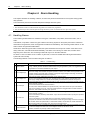
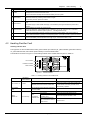
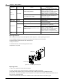
10 Chapter 4 Alarm Handling Chapter 4 Alarm Handling This chapter describes the handling of alarms, as well as the preventive maintenance of the system during system daily operation. The maintenance personnel must have adequate knowledge about the system. Note 1. The maintenance must be conducted under the guidance of related safety regulations. 2. Only the trained personnel with adequate knowledge about the system can maintain the inner part of the system. 4.1 Handling Alarms The monitoring module alarms are classified in four types: critical alarm, major alarm, observation alarm, and no alarm. Critical alarm, major alarm: These two types of alarms have strong impacts on the system performance. Whenever these alarms are generated, users are supposed to handle them immediately. The monitoring module will turn on the alarm indicator and generate audible alarm. Observation: When this type of alarm is raised, the system maintains normal output for a while. If the alarm occurs during watch time, it should be handled immediately. If the alarm occurs during non-watch-time, handle it at the beginning of the watch time. The monitoring module will only turn on the alarm indicator. No alarm: In case of an alarm set as ‘no alarm’ by the users, no visual or audible alarm will be generated and the system will work normally. The handling methods of common alarms are given in Table 4-1. Table 4-1 Troubleshooting No. Alarm 1 Mains Failure 2 AC Voltage High 3 AC Voltage Low 4 DC Volt High 5 DC Volt Low 6 Load Fuse Alarm/ Batt Fuse Alarm Handling method If the failure does not last long, the battery will power the load. If the cause is unknown or the failure lasts too long, a diesel generator should be started. Before using the generator’s power, it is suggested to run the generator five minutes to stabilize the power output Check if the AC Over-voltage point is too low. If yes, reset the value. A mild over-voltage does not affect the system operation. However, the rectifier will stop operation when the mains voltage is more than 305V. Therefore, if the power supply voltage is often high, consult with the power grid maintenance personnel to improve it. Check if the AC Under- voltage point is too high. If yes, reset the value. When the mains voltage is lower than 176V, the output power of the rectifiers will be derated. If the power supply voltage is often low, consult with the power grid maintenance personnel to improve it. 1. Check the system DC output voltage and value of ‘Over’ set through the monitoring module. If the set value is improper, correct it. 2. Find out the rectifier that has caused the alarm. First of all, ensure that the batteries can operate normally. Then switch off the AC input of all rectifiers. Power on the rectifiers one by one. If the over-voltage protection is triggered when a certain rectifier is powered on, that rectifier is the faulty one, replace it 1. Check the system DC output voltage and value of ‘Under’ set through the monitoring module. If the set value is improper, correct it. 2. Check if the alarm is caused by mains failure. If yes, disconnect certain loads to prolong the operation of the whole system. 3. Check if the alarm is due to rectifier fault, find out the faulty rectifier and replace it. 4. Compare the total load current with the total rectifier current during float charge. If the former is bigger than the latter, disconnect partial loads, or add several rectifiers, with at least one rectifier redundant, to make the total rectifier current bigger than 120% of the total load current Check if the MCB or fuse of the route is switched off. If the MCB is open, find out the fault and remove it. Or check the voltage at the alarm fuse. If the voltage is almost 0V, the fuse is normal. Otherwise, the alarm loop is faulty. Please contact Emerson NetSure 211 C23 Embedded Power Supply System User Manual