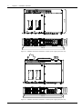
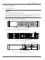
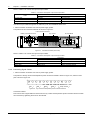
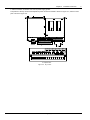
1
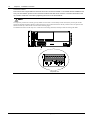
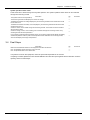
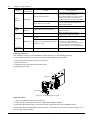
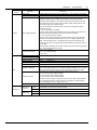
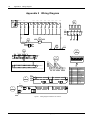
NetSure 211 C45 Embedded Power Supply System User Manual Version V1.0 Revision date September 15, 2009 BOM 31012178 Emerson Network Power provides customers with technical support. Users may contact the nearest Emerson local sales office or service center. Copyright © 2009 by Emerson Network Power Co., Ltd. All rights reserved. The contents in this document are subject to change without notice. Emerson Network Power Co., Ltd. Address: No.1 Kefa Rd., Science & Industry Park, Nanshan District 518057, Shenzhen China Homepage: www.emersonnetworkpower.com.cn E-mail: [email protected] Safety Precautions To reduce the chance of accident, please read the safety precautions very carefully before operation. The "Caution, Note, Warning, Danger" in this book and on the product do not represent all the safety points to be observed, and are only supplement to various safety points. Therefore, the installation and operation personnel must receive strict training and master the correct operations and all the safety points before operation. When operating Emerson products, the operation personnel must observe the safety rules in the industry, the general safety points and special safety instructions specified in this book. Electrical Safety I. Hazardous voltage Danger Danger Some components of the power supply system carry hazardous voltage in operation. Direct contact or indirect contact through moist objects with these components will result in fatal injury. Observe safety rules in the industry when installing the power supply system. The installation personnel must be licensed to operate high voltage and AC power. In operation, the installation personnel are not allowed to wear conductive objects, such as watches, bracelets, bangles and rings. When you spot the cabinet with water or moisture, turn off the power immediately. In moist environment, precautions must be taken to keep moisture out of the power supply system. "Prohibit" warning label must be attached to the switches and buttons that are not permitted to operate during installation. Danger Danger High voltage operation may cause fire and electric shock. The connection and wiring of AC cables must be in compliance with the local rules and regulations. Only those who are licensed to operate high voltage and AC power can perform high voltage operations. II. Tools Warning In high voltage and AC operation, specialized tools must be used. III. Thunderstorm Danger Danger Never operate on high voltage, AC, iron tower or mast in the thunderstorm. In thunderstorms, a strong electromagnetic field will be generated in the air. Therefore the equipment should be well earthed in time to avoid damage by lightning strikes. IV. ESD Note The static electricity generated by the human body will damage the static sensitive elements on PCBs, such as large-scale ICs. Before touching any plug-in board, PCB or IC chip, ESD wrist strap must be worn to prevent body static from damaging the sensitive components. The other end of the ESD wrist strap must be well earthed. V. Short circuit Danger Danger During operation, never short the positive and negative poles of the DC distribution unit of the power supply system or the non-grounding pole and the earth. The power supply system is a constant-voltage DC power device, short circuit will result in equipment burning and endanger human safety. Check the polarity of the cable and connection terminal when performing DC live operations. As the operation space in the DC distribution unit is very tight, please carefully select the operation space. Never wear a watch, bracelet, bangle, ring, or other conductive objects during operation. Use insulated tools. In live operation, keep the arm, wrist and hand tense, so that when the tool in operation slips, the movement of the human body and tool is reduced to a minimum. BLVD The power supply system has battery low voltage disconnection (BLVD) function. BLVD means when battery voltage drops down to 43.2V, the power supply system cuts the load off to prevent over-discharge. BLVD is enabled before delivery, which means that if power outage lasts for a long time or the power supply system fails, there might be BLVD. Users should classify the loads and connect the priority loads to BLVD routes. For vital loads, users can disable BLVD to ensure reliability of the power supply. The method of disabling BLVD is: Set ‘BLVD disabled’ parameter through the monitoring module main menu BLVD. Settings (password: 1) LVD Note Noti Warning ce The advantage of BLVD is protecting the batteries from over-discharge. The disadvantage of BLVD is that when the battery voltage drops down to a certain value, all the loads (including non-priority loads and priority loads) will be cut off due to battery disconnection. The advantage of disabling BLVD is prolonging the power supply of priority loads. The disadvantage is that disabling cannot prevent unwanted power failure due to misoperation or power supply system failure. Others I. Safety Note Noti Warning ce When replacing power input fuses of monitoring module and power distribution units, use the same type fuses to meet the safety requirement. II. Sharp object Warning When moving equipment by hand, wear protective gloves to avoid injury by sharp object. III. Power cable Note Noti Warning ce Please verify the cable labels before connection. IV. Signal cables Note Noti Warning ce The signal cables should be routed at least 150mm away from power cables. Contents Chapter 1 Overview ............................................................................................................................................................ 1 1.1 Model Description ................................................................................................................................................. 1 1.2 Composition And Configuration ............................................................................................................................ 1 1.3 Features ................................................................................................................................................................ 2 Chapter 2 Installation Instruction ......................................................................................................................................... 3 2.1 Safety Regulations ................................................................................................................................................ 3 2.2 Preparation ........................................................................................................................................................... 3 2.3 Mechanical Installation .......................................................................................................................................... 5 2.4 Electrical Installation ............................................................................................................................................. 7 2.4.1 Connecting Power Cables ......................................................................................................................... 7 2.4.2 Connecting Signal Cables ......................................................................................................................... 8 Chapter 3 Installation Testing............................................................................................................................................ 11 3.1 Installation Check And Startup ............................................................................................................................ 11 3.2 Basic Settings ..................................................................................................................................................... 12 3.3 Alarm Check And System Operation Status Check ............................................................................................ 12 3.4 Final Steps .......................................................................................................................................................... 13 Chapter 4 Alarm Handling ................................................................................................................................................. 14 4.1 Handling Alarms.................................................................................................................................................. 14 4.2 Handling Rectifier Fault....................................................................................................................................... 15 Appendix 1 Technical Data ............................................................................................................................................... 18 Appendix 2 Wiring Diagram............................................................................................................................................... 20 Appendix 3 Glossary ......................................................................................................................................................... 22 Chapter 1 Overview Chapter 1 Overview This chapter introduces model description, composition and configuration, and features of NetSure 211 C45 embedded power supply system (abbreviated as ‘system’ hereinafter). 1.1 Model Description The model description of the system is given in Figure 1-1. NetSure 211 C 4 5 - S1 Configuration Version No. The number of the rectifier in the typical power supply system: 4 Region: China Type of the rectifier: R48-1000 Brand name of the system Figure 1-1 Model description 1.2 Composition And Configuration NetSure 211 C45 power supply system has two models, NetSure 211 C45-S1 and NetSure 211 C45-S2. The appearances of the two systems are shown in Figure 1-2 and Figure 1-3. Rectifier Monitoring module Load MCB Battery MCB Dry contact and temperature probe connection terminal Load socket Battery socket Figure 1-2 Appearance of NetSure 211 C45-S1 power supply system Rectifier Monitoring module Load MCB Battery MCB Figure 1-3 Appearance of NetSure 211 C45-S2 power supply system NetSure 211 C45 Embedded Power Supply System User Manual 1 2 Chapter 1 Overview The configuration of the system is listed in Table 1-1. Table 1-1 Configuration of the system Component Configuration NetSure 211 C45-S1 NetSure 211 C45-S2 Rectifier Model: R48-1000 Standard configuration: 4 pieces Monitoring module Model: M522B, M523B or M221B Standard configuration: 1 piece AC power distribution AC input mode: L + N + PE/220V, no AC input MCB AC input mode: L + N + PE/220V, 1 × 40A/2P MCB DC power distribution 8 load MCBs: 4 × 20A/1P, 4 × 25A/1P 4 load MCBs: 2 × 20A/1P, 2 × 10A/1P Battery routes 2 battery MCBs: 2 × 63A/1P 1 battery MCB: 1 × 63A/1P Others Two digital input ports, two dry contact output ports, two temperature sensor ports One digital input port, two dry contact output ports, two temperature sensor ports The monitoring module is available in three different models. Their configurations are listed in Table 1-2. Table 1-2 Configuration of the monitoring module Models Configuration M522B 2DI + 2DO, LCD display, network port, RS232 port M523B 2DI + 2DO, LCD display, RS232 port M221B 2DI + 2DO, no LCD display, three LED indicators indicating operation status of the system, RS232 port 1.3 Features The rectifier uses the active Power Factor Compensation (PFC) technology, raising the power factor to 0.99. The system has wide AC input voltage range: 90Vac ~ 290Vac. The rectifier uses soft switching technology, raising the efficiency to 91%. The rectifier has ultra-low radiation. With advanced EMC design, the rectifier meets international standards such as CE, NEBS and YD/T983. Both the conducted and radiated interference reach Class B. The rectifier safety design complies with UL, CE and NEBS standards. The rectifier is of high power density. The rectifier is hot pluggable. It takes less than 1min to replace a rectifier. The rectifier has two over-voltage protection methods: hardware protection and software protection. The latter one also has two optional modes: lock-out at the first over-voltage and lock-out at the second over-voltage. The monitoring module has perfect battery management. The management functions include battery low voltage disconnection (BLVD), temperature compensation, auto voltage regulation, stepless current limiting, battery capacity calculation, on-line battery test, and so on. The monitoring module can save up to 200 pieces of historical alarm records, and 10 sets of battery test data records. The monitoring module is of network design. With an RS232 port, Ethernet, dry contacts and other communication ports provided, flexible networking is enabled to achieve remote monitoring and unattendance. The system has complete fault protection and fault alarm functions. NetSure 211 C45 Embedded Power Supply System User Manual Chapter 2 Installation Instruction 3 Chapter 2 Installation Instruction This chapter introduces installation and cable connection. Before installation, please read through safety regulations, and then follow the instructions provided in this chapter to carry out the installation and cable connection. 2.1 Safety Regulations Certain components in this system carry hazardous voltage and current. Always follow the instructions below: 1. Only the adequately trained personnel with satisfactory knowledge of the power system can carry out the installation. The most recent revision of these safety rules and local safety rules in force shall be adhered to during the installation. 2. All external circuits that are below -48V and connected to the power system must comply with the requirements of SELV as defined in IEC 60950. 3. Make sure that the power (mains and battery) to the system is cut off before any operations can be carried out within the system cabinet. 4. The power cabinets shall be kept locked and placed in a locked room. The key keeper should be the one responsible for the system. 5. The wiring of the power distribution cables should be arranged carefully so that the cables are kept away from the maintenance personnel. 2.2 Preparation Unpacking inspection The equipment should be unpacked and inspected after it arrives at the installation site. The inspection shall be done by representatives of both the user and Emerson Network Power Co., Ltd. To inspect the equipment, you should open the packing case, take out the packing list and check against the packing list that the equipment is correct and complete. Make sure that the equipment is delivered intact. Cables The cable should be selected in accordance with relevant industry standards. 1. Cable specifications of NetSure 211 C45-S1 power supply system It is recommended to use the RVVZ cables as AC cables. The cable should reach at least +70°C temperature durability. Select the AC cable Cross-Sectional Area (CSA) according to Table 2-1. Table 2-1 AC cable CSA selection Connector AC cable CSA AC connection block 1.5mm2 (AWG14) ~ 2.5mm2 (AWG12) The CSA of DC cable depends on the current flowing through the cable, the allowable voltage drop and load peak current. The recommended load peak current is 1/2 to 2/3 of MCB or fuse capacity. Select the battery cable CSA according to Table 2-2. Select the load cable CSA according to Table 2-3. Table 2-2 Battery cable CSA selection Battery MCB rated current Max. battery current 63A 60A Min. cable CSA 2.5mm2 × 2 AWG12 × 2 Max. cable length (allowable voltage drop: 0.5V) 2.5m 3.8m Max. cable CSA 4mm2 × 2 AWG10 × 2 Max. cable length (volt drop: 0.5V, with max. CSA) 4m 4.8m Note: 1. The specs are applicable at ambient temperature of 25°C. 2. The battery cable should reach at least +90°C heat durability. It is recommended to use double-insulated copper-core flame-retardant cable as battery cable NetSure 211 C45 Embedded Power Supply System User Manual 4 Chapter 2 Installation Instruction Table 2-3 Load cable CSA selection Load route rated current Max. output current 20A 20A 25A 25A Min. cable CSA 2.5mm2 AWG12 2.5mm2 AWG12 Max. cable length (volt drop: 0.5V, with min. CSA) 3.1m 4.6m 2.5m 3.6m Max. cable CSA 4mm2 AWG10 2.5mm2 AWG10 Max. cable length (volt drop: 0.5V, with max. CSA) 5m 6.1m 4m 4.8m Note: 1. The specs are applicable at ambient temperature of 25°C. 2. The battery cable should reach at least +90°C heat durability. It is recommended to use double-insulated copper-core flame-retardant cable as battery cable The CSA of the system earth cable should be the same as that of the largest power distribution cable and not less than 1.5mm2. The earth terminal is one M5 bolt. 2. Cable specifications of NetSure 211 C45-S2 power supply system It is recommended to use the RVVZ cables as AC cables. The cable should reach at least +70°C temperature durability. Select the AC cable Cross-Sectional Area (CSA) according to Table 2-4. Table 2-4 AC cable CSA selection Connector AC cable CSA AC input MCB 4mm2 (AWG10) ~ 10mm2 (AWG6) The CSA of DC cable depends on the current flowing through the cable, the allowable voltage drop and load peak current. The recommended load peak current is 1/2 to 2/3 of MCB or fuse capacity. Select the battery cable CSA according to Table 2-5. Select the load cable CSA according to Table 2-6. Table 2-5 Battery cable CSA selection Battery MCB rated current Max. battery current 63A 60A Min. cable CSA 10mm2 AWG6 Max. cable length (allowable voltage drop: 0.5V) 4.3m 5.6m Max. cable CSA 16mm2 AWG4 Max. cable length (volt drop: 0.5V, with max. CSA) 6.9m 8.9m Note: 1. The specs are applicable at ambient temperature of 25°C. 2. The battery cable should reach at least +90°C heat durability. It is recommended to use double-insulated copper-core flame-retardant cable as battery cable Table 2-6 Load cable CSA selection Load route rated current Max. output current 20A 20A 10A 10A Min. cable CSA 2.5mm2 AWG12 1.5mm2 AWG14 Max. cable length (volt drop: 0.5V, with min. CSA) 3.1m 4.6m 3.7m 5.8m Max. cable CSA 6mm2 AWG8 6mm2 AWG8 Max. cable length (volt drop: 0.5V, with max. CSA) 7.5m 10.7m 15.1m 21.4m Note: 1. The specs are applicable at ambient temperature of 25°C. 2. The battery cable should reach at least +90°C heat durability. It is recommended to use double-insulated copper-core flame-retardant cable as battery cable The CSA of the system earth cable should be the same as that of the largest power distribution cable and not less than 1.5mm2. The earth terminal is one M5 bolt. NetSure 211 C45 Embedded Power Supply System User Manual Chapter 2 Installation Instruction 5 The specifications of RS232 cable of the two systems are the same. The RS232 cable is shown in Figure 2-1. RJ45 DB9 X2 X1 A A amplified view Figure 2-1 RS232 cable The definition of the RS232 cable connector is shown in Table 2-7. Users should make RS232 cable according to the description in Table 2-7. Table 2-7 Definition of the RS232 cable connector DB9 RJ45 X1.2 X2.3 X1.3 X2.6 X1.4 X2.7 X1.5 X2.4 & X2.5 X1.6 X2.2 X1.7 X2.8 X1.8 X2.1 2.3 Mechanical Installation 1. Install brackets. Fix the brackets on the power supply subrack with bolts. Users can choose proper installation position according to actual instance. 2. Install the power supply subrack. Fix the subrack in the cabinet with fixing screws. The installation dimensions are shown in Figure 2-2 and Figure 2-3. NetSure 211 C45 Embedded Power Supply System User Manual 76.20 88.00 289.80 Installation Instruction 465.00 482.00 Figure 2-2 Installation dimensions of NetSure 211 C45-S1 power supply system (unit: mm) 289.8 Chapter 2 76.20 88.00 6 465.00 482.00 Figure 2-3 Installation dimensions of NetSure 211 C45-S2 power supply system (unit: mm) NetSure 211 C45 Embedded Power Supply System User Manual Chapter 2 Installation Instruction 7 2.4 Electrical Installation 2.4.1 Connecting Power Cables Danger Danger 1. Switch off all MCBs and fuses before the electrical connection. 2. Only the qualified personnel shall do the power cable connection. 3. The batteries may have dangerous current. Before connecting battery cables, make sure that the battery fuses at the system side and the battery MCBs at the battery side are switched off. If there are no battery MCBs at the battery side, you should disconnect any one of the connectors between battery cells to avoid live state of the system after installation. 4. Be careful not to reversely connect the battery. Otherwise, both the battery and the system will be damaged! 1. Cable connection of NetSure 211 C45-S1 power supply system Before connecting AC input cables, remove the back cover of the system, as shown in Figure 2-4. Back cover AC cable entry hole Figure 2-4 Back view of the system The positions of the connection terminals are shown in Figure 2-5 and Figure 2-6. Load socket Dry contact and temperature probe connection terminal Figure 2-5 Connection terminals (front view) AC input socket of upper layer rectifier Earth terminal AC input socket of lower layer rectifier Figure 2-6 Battery socket Connection terminals (back view, back cover removed) NetSure 211 C45 Embedded Power Supply System User Manual 8 Chapter 2 Installation Instruction Refer to Table 2-8 to connect the input and output cables. Table 2-8 Connection descriptions of input and output cables Connection Cable From To AC input cable AC power AC input socket DC output cable Load socket Load Battery cable Battery string Battery socket Lead the AC input cables through the AC cable entry hole, and reinstall the back cover. 1. Cable connection of NetSure 211 C45-S2 power supply system The positions of the connection terminals are shown in Figure 2-7. Battery connection terminal Load connection terminal Dry contact AC input MCB Earth terminal Figure 2-7 Connection terminals (back view) Refer to Table 2-9 to connect the input and output cables. Table 2-9 Connection descriptions of input and output cables Connection Cable From To AC input cable AC power AC input MCB DC output cable Load connection terminal Load Battery cable Battery string Battery connection terminal 2.4.2 Connecting Signal Cables 1. Cable connection of NetSure 211 C45-S1 power supply system The position of the dry contact and temperature probe connection terminal is shown in Figure 2-5, and the screen print is shown in Figure 2-8. + DI1 Figure 2-8 + DI2 NO COM NO COM PS Ground T1 DO1 DO2 T2 Temp. sensor Dry contact and temperature probe connection terminal Connection method: Peel one end of the signal cable and insert it into the dry contact and temperature probe connection terminal. Fasten the connection by tightening the screw on the terminal. NetSure 211 C45 Embedded Power Supply System User Manual Chapter 2 Installation Instruction 2. Cable connection of NetSure 211 C45-S2 power supply system The position of the dry contact and temperature probe connection terminal is shown in Figure 2-7, and the screen print is shown in Figure 2-9. A A amplified view Figure 2-9 Dry contact NetSure 211 C45 Embedded Power Supply System User Manual 9 10 Chapter 2 Installation Instruction Connection method: Peel one end of the signal cable and insert the end to OT connection terminal or UT terminal with M4 installation bolt. Carry out the insulation process to the connection terminals and cable ends. Insert the connection terminals into the dry contacts. Fasten the connection by tightening the screw on the terminal block. Note Noti Warning ce The output dry contacts are normally open by default. If users want to use normally-closed contacts, they need to pull out the monitoring module and change the NO-COM connections to NC-COM connections at the dry contact socket. The position and definition of the dry contact socket is shown in the following figure. The default associations of the relays are: critical alarm associating with DO1, and major alarm associating with DO2. A A amplified view NetSure 211 C45 Embedded Power Supply System User Manual Chapter 3 Installation Testing 11 Chapter 3 Installation Testing This chapter introduces procedures of installation testing. The corresponding safety rules shall be adhered to in the test. 3.1 Installation Check And Startup Before the test, inform the chief manufacturer representative. Only the trained electrical engineer shall conduct the system testing. Remove metal objects that may cause shortcircuit, such as rings, watches, and so on. During operation, watch out for hazardous voltage, and avoid personnel injury and property damage. Before the test, ground the equipment properly. Installation check must be done before testing, then the batteries can be charged for the first time. Make sure that the AC input MCB and load MCBs are switched off. Make sure that all the devices are properly installed. Check the system according to the following items listed below. Installation check Check item Verify all the MCBs, fuses and cables Verify the system grounding, input and output cable connection Verify the battery cell number, connection, and battery string polarities Make sure all the cable connections are firm and reliable Make sure all the communication cables and alarm cables are connected to the monitoring module. Check that the temperature sensor, if any, has been installed correctly OK Comments Startup preparations Check item Make sure that all the MCB are switched off and all the fuses are removed Measure the AC input voltage. Make sure the input voltage is within the allowable range Check that the battery string circuit is not closed Connect the disconnected batteries to the battery string circuit Measure with a voltmeter across the connection points of each battery and make sure that the polarity is right. For a lead-acid battery with 24 cells, the voltmeter should read 2.0V/cell ~ 2.1V/cell or 48V/battery ~ 51V/battery. If the voltage of certain cell is lower than 2.0V, that cell must be replaced Check with an ohmmeter that there is no short circuit between the positive & negative distribution busbars, or between the positive & negative battery poles (Note: Pull out all modules before the check and restore them after the check) OK Comments Umin=___V Umin=___V Startup Check item Switch on the system AC input MCB, and the monitoring module should display the correct voltage and current values The green indicator on the rectifier should turn will be on and the fan should will start running. After a certain delay, the monitoring module should show that the power supply voltage is 53.5V Check the system voltage and busbar polarity with a voltmeter. The voltage difference between the measured value and displayed value should be less than ± 0.3V Start and stop each rectifier by inserting and unplugging the rectifiers. Check their output voltages NetSure 211 C45 Embedded Power Supply System User Manual OK Comments 12 Chapter 3 Installation Testing 3.2 Basic Settings When the system is put into service for the first time, the parameters of the monitoring module must be set based on the actual system configuration, battery number and capacity, user’s charge current limiting and other functional requirements. Only after that can the monitoring module display system operation information and control the output. To change the settings, enter the main menu Settings (password: 1) Battery Settings Batt. Selection submenu, set the ‘Mode’ parameter to ‘Manual’, and then return to the submenus of Battery Settings menu to set the parameters For detailed setting method, see SCU + Series Monitoring Module User Manual. Check item The system model has been set correctly in factory before delivery, check that the setting agrees with the actual system (48V/SET) The battery string number set at the monitoring module should be the same as the number actually connected (Default: 2) Set the battery capacity according to the total capacity of all the battery connected to the system. Default: 300Ah Configure the temperature compensation coefficient according to the battery manufacturer’s requirement. Setting range: 0mV/°C ~ 500mV/°C. Default: 72mV/°C (if no temperature sensor is installed, do not set this parameter) Set the charge current limit according to your needs. Setting range: 0.1C10 ~ 0.25C10 (Default: 0.1C10) Set the monitoring module according to the voltage suggested by the battery supplier. Float Charge (FC) voltage range: 42V ~ Boost Charge (BC) voltage. Default: 53.5V. BC voltage range: FC voltage ~ 58V. Default: 56.4V. For batteries that do not need BC, set the BC voltage to FC voltage plus 0.1V Measure the battery voltage with a multimeter and record it. Enter main menu OK Comments Maintenance (password: 1) RectTrim submenu. Set the output voltage of the rectifier to the value of the battery voltage. Insert the battery fuse. Set the output voltage of the rectifier to 53.5V Enter the Batt. Selection submenu. Set the ‘Mode’ parameter to ‘Auto’ Note*: if the capacity of the battery is smaller than 50Ah, set the ‘Capacity’ to 50Ah 3.3 Alarm Check And System Operation Status Check Alarm check Check that all functional units can trigger alarms and the alarms can be displayed on the monitoring module. Check item Pull out one rectifier, and the ‘Rect N Com Failure’ alarm should be triggered. Insert the rectifier in, and the alarm should disappear. Repeat the same procedures on other rectifiers Switch off battery MCB 1, and the ‘Batt1 Failure’ alarm should be triggered. Switch on battery MCB 1, and the alarm should be cleared. Repeat the same on battery MCB 2 Switch off a load MCB connected to load, and the alarm ‘Load Fuse N Failure’ should be triggered. Switch on the load MCB, and the alarm should be cleared. Repeat the same on other load MCBs Switch off the battery MCBs. Keep only one rectifier in operation. Through the monitoring module, adjust the rectifier FC voltage to make it lower than the alarm point. The alarm ‘DC Voltage Low’ should be triggered Keep the rectifiers in operation. Set through the monitoring module the battery management parameter to ‘Manual’. Enter the maintenance menu at the monitoring module. Select ‘Disconnect’ and confirm it. The battery protection contactor should be open, and the ‘BLVD’ alarm should be displayed at the monitoring module OK Note: The monitoring module will give alarms approximately 10s after the alarms are triggered. Enter main menu view the alarm information NetSure 211 C45 Embedded Power Supply System User Manual Comments Operation to Chapter 3 Installation Testing 13 System operation status check There should be no alarms during normal system operation. The system operation status check can be conducted through the monitoring module. Check item The system model is correct (48V/SET) The monitoring module should display the correct AC voltage The difference between the voltage displayed by the monitoring module and the actual value should be less than ±0.3V The difference between the battery current displayed by the monitoring module and the actual value should be less than 1% Check the number of the rectifier through the monitoring module. The number should be consistent with the actual number Check the voltage, current, current limiting point of rectifiers through the monitoring module. They should agree with the actual parameters For the system configured with temperature sensor, the monitoring module should display the battery ambient temperature. Hold the probe of the temperature sensor and watch the monitoring module, which should display the change of temperature OK Comments 3.4 Final Steps Check item Make sure that materials irrelevant to the equipment have been all removed Fill in the installation report and hand it over to the user Fill in the parameter table on the cabinet door OK Comments If any defect is found in this equipment, inform the personnel responsible for the contract. If repairing is needed, please fill in the FAILURE REPORT and send the report together with the defective unit to the repairing center for fault analysis. NetSure 211 C45 Embedded Power Supply System User Manual 14 Chapter 4 Alarm Handling Chapter 4 Alarm Handling This chapter describes the handling of alarms, as well as the preventive maintenance of the system during system daily operation. The maintenance personnel must have adequate knowledge about the system. Note 1. The maintenance must be conducted under the guidance of related safety regulations. 2. Only the trained personnel with adequate knowledge about the system can maintain the inner part of the system. 4.1 Handling Alarms The monitoring module alarms are classified in four types: critical alarm, major alarm, observation alarm, and no alarm. Critical alarm, major alarm: These two types of alarms have strong impacts on the system performance. Whenever these alarms are generated, users are supposed to handle them immediately. The monitoring module will turn on the alarm indicator and generate audible alarm. Observation: When this type of alarm is raised, the system maintains normal output for a while. If the alarm occurs during watch time, it should be handled immediately. If the alarm occurs during non-watch-time, handle it at the beginning of the watch time. The monitoring module will only turn on the alarm indicator. No alarm: In case of an alarm set as ‘no alarm’ by the users, no visual or audible alarm will be generated and the system will work normally. The handling methods of common alarms are given in Table 4-1. Table 4-1 Troubleshooting No. Alarm 1 Mains Failure 2 AC Voltage High 3 AC Voltage Low 4 DC Volt High 5 DC Volt Low 6 Load Fuse Alarm/ Batt Fuse Alarm Handling method If the failure does not last long, the battery will power the load. If the cause is unknown or the failure lasts too long, a diesel generator should be started. Before using the generator’s power, it is suggested to run the generator five minutes to stabilize the power output Check if the AC Over-voltage point is too low. If yes, reset the value. A mild over-voltage does not affect the system operation. However, the rectifier will stop operation when the mains voltage is more than 305V. Therefore, if the power supply voltage is often high, consult with the power grid maintenance personnel to improve it. Check if the AC Under- voltage point is too high. If yes, reset the value. When the mains voltage is lower than 176V, the output power of the rectifiers will be derated. If the power supply voltage is often low, consult with the power grid maintenance personnel to improve it. 1. Check the system DC output voltage and value of ‘Over’ set through the monitoring module. If the set value is improper, correct it. 2. Find out the rectifier that has caused the alarm. First of all, ensure that the batteries can operate normally. Then switch off the AC input of all rectifiers. Power on the rectifiers one by one. If the over-voltage protection is triggered when a certain rectifier is powered on, that rectifier is the faulty one, replace it 1. Check the system DC output voltage and value of ‘Under’ set through the monitoring module. If the set value is improper, correct it. 2. Check if the alarm is caused by mains failure. If yes, disconnect certain loads to prolong the operation of the whole system. 3. Check if the alarm is due to rectifier fault, find out the faulty rectifier and replace it. 4. Compare the total load current with the total rectifier current during float charge. If the former is bigger than the latter, disconnect partial loads, or add several rectifiers, with at least one rectifier redundant, to make the total rectifier current bigger than 120% of the total load current Check if the MCB or fuse of the route is switched off. If the MCB is open, find out the fault and remove it. Or check the voltage at the alarm fuse. If the voltage is almost 0V, the fuse is normal. Otherwise, the alarm loop is faulty. Please contact Emerson NetSure 211 C45 Embedded Power Supply System User Manual Chapter 4 No. Alarm 7 LVD2 8 Rect Failure 9 Rect Protect 10 Rect Fan Fails 11 Rect Not Respond 12 Batt Over Temp Alarm Handling 15 Handling method 1. Check if there is a mains failure, and the battery voltage is lower than the ‘BLVD’ value, or the battery discharge time is more than the ‘BLVD Time’. 2. Check if someone manually disconnected the battery from the system The red LED on the rectifier will turn on. 1. Reset the rectifier by powering it off and then on again. 2. If the alarm persists, replace the rectifier Check if the mains voltage is outside the range of 80V (AC under-voltage point) ~ 295V (AC over-voltage point). If the power supply is often outside this range, consult with the power grid maintenance personnel to improve it 1. Check whether the rectifier fan is still working. 2. If the fan stands still, check whether the fan is blocked or not. If yes, clean it; if not, or if the fault persists after the fan is cleaned, replace it (see 4.2 Handling Rectifier Fault) Check if the communication between rectifier and monitoring module failed. If the communication is normal, restart the rectifier by pulling it out and pushing back in. If the alarm persists, replace the rectifier 1. Check if there is a battery internal fault. If yes, replace the battery. 2. Check if the battery room temperature is too high. If yes, cool down the battery room 4.2 Handling Rectifier Fault Handling indicator fault The symptoms of usual rectifier faults include: green indicator (run indicator) off, yellow indicator (protection indicator) on, yellow indicator blink, red indicator (fault indicator) on and red indicator blink. The indicators are shown in Figure 4-1 and handling methods of the rectifier faults are given in Table 4-2. Run indicator Protection indicator Fault indicator R48-1000 Figure 4-1 Rectifier indicator Table 4-2 Handling methods of the rectifier faults Symptom Monitoring module alarms Causes No input/output voltage Run indicator off No alarm Run indicator blinks No alarm Yellow indicator on Rect over temp Assistant power source of the rectifier fails The monitoring module performs operations upon the rectifier AC input voltage abnormal Fan blocked OverVentilation path blocked at temperature the inlet or vent protection Ambient temperature too due to: high or the inlet too close to a heat source NetSure 211 C45 Embedded Power Supply System Handling methods Make sure there is input/output voltage Change the position of the faulty module with normal module. If the faulty module cannot work normally, replace it Make sure the AC input voltage is normal Remove the object that blocks the fan Remove the object at the inlet or vent Decrease the ambient temperature or remove the heat source User Manual 16 Chapter 4 Alarm Handling Symptom Monitoring module alarms Causes Handling methods Check whether the rectifier communication is normal. If not, check whether the communication cable is in normal connection. If the communication is normal while the protection indicator is on, replace the rectifier Change the position of the faulty module with normal module. If the faulty module cannot work normally, replace it Ensure AC input voltage normally Current sharing imbalance Yellow indicator on Rect protect Power factor compensation internal under-voltage or over-voltage AC input over-voltage Yellow indicator blinks Red indictor on Red indicator blinks Rect Not Respond Rectifier communication interrupted Check whether the communication cable is in normal connection Rect HVSD Rectifier over-voltage Reset the rectifier. If the protection is triggered again, replace the rectifier Two or more rectifiers have the same ID number Contact Emerson for maintenance Serious current sharing imbalance (current imbalance > ± 3%) Check whether the rectifier communication is normal. If not, check whether the communication cable is in normal connection. If the communication is normal while the protection indicator is on, replace the rectifier Fan fault Replace the fan Rect Failure Rect Fan Fails Replacing rectifier fan If the rectifier fan is faulty, it should be replaced. Refer to Figure 4-2, for the replacing procedures: 1. Use a Phillips screwdriver to remove the two fixing screws and pull out the front panel. 2. Unplug the power cable of the fan and remove the fan. 3. Plug in the new fan. 4. Install the new fan, with fan blowing-direction inward. 5. Replace the front panel. Fixing hole Fan Fixing hole Front panel Figure 4-2 Disassembling the front panel Replacing rectifier 1. Take a new rectifier and check it for any damage. 2. Loosen the fixing screw of the handle of the rectifier with a Phillips screwdriver. 3. Press the rectifier handle to pop it out. Pull out the faulty rectifier from the rack by grabbing its handle. Be careful with the rectifier just pulled out from the system, as it could be very hot due to long-term operation. Do not let it slip away and get damaged. NetSure 211 C45 Embedded Power Supply System User Manual Chapter 4 Alarm Handling 17 4. Hold the rectifier handle, push the new rectifier into the slot and make sure the connection is good. After a brief delay, the rectifier RUN indicator will turn on and the fan will start running. 5. Check that the new rectifier works normally. You should make sure that: 1) The monitoring module recognizes the new rectifier. 2) The new rectifier shares current with other rectifiers. 3) When this new rectifier is pulled out, there is a corresponding alarm and the monitoring module displays the alarm. If the new rectifier passes all the above tests, the replacement is a success. 6. Push the handle back into the front panel to lock the rectifier. 7. Fix the fixing screw of the handle of the rectifier with a Phillips screwdriver. NetSure 211 C45 Embedded Power Supply System User Manual 18 Appendix 1 Technical Data Appendix 1 Technical Data Table 1 Technical data Parameter category Environmental AC input DC output AC input alarm and protection DC output alarm and protection Parameter Operating temperature Storage temperature Relative humidity Altitude Pollution level Others Input phase voltage Input voltage range Input frequency Max input current Power factor Over-voltage level Rated output voltage Output voltage range Output current Total regulation Efficiency Noise (peak-peak) Weighted noise AC input over-voltage alarm point AC input over-voltage alarm recovery point AC input under-voltage alarm point AC input under-voltage alarm recovery point AC input over-voltage protection point AC input over-voltage protection recovery point AC input under-voltage protection point AC input under-voltage protection recovery point DC output over-voltage alarm point DC output over-voltage alarm recovery point DC output under-voltage alarm point DC output under-voltage alarm recovery point BLVD point Current sharing Rectifier Derate by input (45°C) Description -5°C ~ 40°C -40°C ~ 70°C ≤ 90%RH ≤ 2000m (derating is necessary above 2000m) Level 2 No conductive dust or erosive gases. No danger of explosion 220Vac 90Vac ~ 290Vac 45Hz ~ 65Hz Single phase, input current of each rectifier ≤ 7A ≥ 0.99 Level 2 -53.5Vdc -42.3Vdc ~ -57.6Vdc 80A ≤ ±1% ≥ 90% ≤ 200mV ≤ 2mV Default: 280Vac ± 10Vac, cofigurable through monitoring module 15Vac lower than the AC input over-voltage alarm point Default: 180Vac ± 10Vac, configurable through monitoring module 15Vac higher than the AC input under-voltage alarm point Default: 305Vac ± 5Vac 10Vac lower than the AC input over-voltage protection point Default: 80Vac ± 5Vac 15Vac higher than the AC input under-voltage protection point Default: 57.6Vdc ± 0.2Vdc, configurable through monitoring module 0.5Vdc lower than the over-voltage alarm point Default: 45.0Vdc ± 0.2Vdc, configurable through monitoring module 0.5Vdc higher than the under-voltage alarm point Default: 43.2Vdc ± 0.2Vdc, configurable through monitoring module The imbalance is better than ± 5% rated output current. Test current range: 10% ~ 100% rated current. The imbalance is better than ± 3% rated output current. Test current range: 50% ~ 100% rated current Input voltage: 176Vac ~ 290Vac, rectifier max. output power: 50% rated power, 1000W Input voltage: 90Vac ~ 176Vac, rectifier output power: linear derating power NetSure 211 C45 Embedded Power Supply System User Manual Appendix 1 Parameter category Parameter Output delay Fan speed Rectifier Over-voltage protection Temperature derating CE RE Immunity to EFT Immunity to ESD Immunity to Surges Acoustic noise Insulation resistance EMC Insulation strength ROHS Mechanical Size (W ×D ×H) (mm) Weight (kg) System Rectifier System Rectifier Technical Data 19 Description Output voltage can rise slowly upon rectifier start up. The rise time is configurable Rectifier fan speed can be adjusted automatically The rectifier provides over-voltage hardware and software protection. The hardware protection point is between 59V and 60V, and manual resetting is required to restore operation. The software protection point is between 56V and 59V (required to be 0.5Vdc higher than the output voltage, default: 59Vdc), and can be set through the monitoring module. There are two software protection modes, which can be selected through the software at the host: 1. Lock out at the first over-voltage Once the output voltage reaches protection point, the rectifier will shut down and hold that state. Manual resetting is required to restore the operation. 2. Lock out at the second over-voltage When the output voltage reaches the software protection point, the rectifier will shutdown, and restart automatically after 5s. If the over-voltage happens again within a set time (default: 5min. Configurable through monitoring module), the rectifier will shut down and hold that state. Manual resetting is required to restore the operation. Manual resetting: Resetting can be done manually through the monitoring module, or by removing the rectifier from system -20°C ~ 45°C, 1000W. 45°C ~ 75°C, linear derating. > 75°C, 0W Class A EN55022 Level 4 EN61000-4-4 Level 3 EN61000-4-2 Level 4 EN61000-4-5 ≤ 55dB (A) (When the ambient temperature is 25°C) At temperature of 20°C ~ 30°C and relative humidity not bigger than 90%RH, apply a test voltage of 500Vdc. The insulation resistances between AC circuit and earth, DC circuit and earth, and AC and DC circuits are all not less than 2MΩ (Rectifiers and monitoring module from the system before the test.) AC to DC circuits: 50Hz, 3000Vac (RMS). AC circuit to earth: 50Hz, 2500Vac (RMS). DC circuit to earth: 50Hz, 1000Vac (RMS). Assistant circuit (not directly connected to the host circuit): 50Hz, 500Vac (RMS). For all the three tests above, there should be no breakdown or flashover within 1min, with leakage current not bigger than 10mA Compliant with R5 standard 437 × 289 × 88 (for NetSure 211 C45-S2 power supply system, the size does not include MCB or connection terminal at the back) 40.8 × 241.1 × 86.5 ≤ 12.5 ≤ 1.5 NetSure 211 C45 Embedded Power Supply System User Manual 20 Appendix 2 Wiring Diagram Appendix 2 Wiring Diagram BAT1- J2 6 BAT2- LOAD1- LOAD2- LOAD3- LOAD4- LOAD5- LOAD6- LOAD7- LOAD8- 5 W02 Busbar+ Alarm board DA411X3 4-X1-30 4-X1-28 4-X2-5 6-J2-1 6-J2-2 6-J2-3 6-J2-4 6-J2-5 6-J2-6 6-J2-7 6-J2-8 LOAD OUTPUT + J1 LCB1 Load LCB2 Load LCB3 Load LCB4 Load LCB5 Load LCB6 Load LCB7 Load LCB8 Load Line Line Line Line Line Line Line Line BATCB3 Line Load BATCB2 Line Load BATCB1 Line Load 4-X1-29 1 2 3 4 5 4-X1-47 4-X1-49 6 8 9 BAT2+ BAT3+ 10 W02 7-J218 4-X1-35 2 4-X1-22 3 W02 W02 3-4 4-X1-20 Shunt BLVD BAT1+ 1 1 2-X1-32 2-X1-44 4-X1-39 4-X1-41 2 2 1 4 5-6 3 2 6 5 X1 4-X1-36 7-J217 4-X1-31 4-X1-46 1 Busbar- 1 4 2 10 SCU+ connector Dry contactor 12-9 12-11 12-12 6-J1-1 1-2 5-6 3-X1-1 3-X1-2 5-6 5-6 X1 W01 9 8-J207-2 8-J207-1 2-2 2-1 BATCB2-line 12 11 X2 49 47 45 43 41 39 37 35 33 31 29 27 25 23 21 19 17 15 13 11 9 7 5 3 1 50 48 46 44 42 40 38 36 34 32 30 28 26 24 22 20 18 16 14 12 10 8 6 4 2 PSK4820-6 12-4 12-3 12-2 12-1 When the third battery CB needed, this kit and M521B should be configured in system that differ from the standard configuration. + - DI1 + - DI2 NO COM NC NO DO1 COM NC DO2 4-X1-50 12-10 8 4-X1-4 4-X1-2 H52 (L1) (L2) J207 L1 N 1-1 7 J217 DC- SA411X2 (L1) (L2) PE J218 DC+ Rec1 1 12-8 12-7 12-6 12-5 NOTES: SA411X3 2 IB0 connector BATCB3-line BATCB1-line 3-1 1-X1-6 3-1 1-2 8-H52 49 47 45 43 41 39 37 35 33 31 29 27 25 23 21 19 17 15 13 11 9 7 5 3 1 50 48 46 44 42 40 38 36 34 32 30 28 26 24 22 20 18 16 14 12 10 8 6 4 2 Rec2 L1 N 5-1 Figure 1 Wiring diagram of Netsure 211 C45-S1 NetSure 211 C45 Embedded Power Supply System User Manual NO. 1 2 3 4 5 6 7 8 9 10 11 12 W01 Connect from 10-1 10-2 10-3 10-4 10-5 10-6 10-7 10-8 10-9 10-10 10-11 10-12 Connect to 9-D11+ 9-D119-D12+ 9-D129-DO1-NO 9-DO1-COM 9-DO2-NO 9-DO2-COM 4-X1-19 8-H52 4-X1-25 4-X1-23 W03 12-LOAD4- 12-LOAD3- 12-LOAD2- 12-LOAD1- W03 X5 4 321 1-2 5-J1-1 7-J218 3-X1-2 3-X1-1 LCB4 Load Line 6-H52 W03 3 2 Shunt 4-22 BLVD 1 4-32 4-44 10 AC CB 4-20 1 1 6-J207-1 6-J207-2 2-1 2-2 3-X1-6 3-1 BATCB-line 49 47 45 43 41 39 37 35 33 31 29 27 25 23 21 19 17 15 13 11 9 7 5 3 1 50 48 46 44 42 40 38 36 34 32 30 28 26 24 22 20 18 16 14 12 10 8 6 4 2 W03 LCB3 Load Line 4-29 5-J2-6 LCB2 Load Line J1 BAT CB Load LCB1 Load Line Line DA411X3 5-J2-5 3-1 5-J2-4 7-J217 7-J218 5-J2-3 1-2 J2 W03 5 Alarm board 6-H52 4-30 3 2 2 1 4 7-J218 3 2 6 5 X1 4-39 4-41 4-36 7-J217 2 1 Busbar- 4-31 4-46 6 4 L N W04 1 SA411X3 2 6-N 7-N W04 6-L1 7-L1 4-50 4-X5-3 4-4 H52 4-2 J212 DC- J207 J208 J211 DC+ (L1) (L2) L1 N 7-J217 W05 7-J218 W05 10-4 10-2 W04 W04 9 W07 8 W06 7-J215 1-1 10-J212 J215 J218 DC+ J216 J217 DC- (L1) (L2) 10-4 10-2 W04 W04 - DI2 NO COM NC DO1 NO COM NC DO2 11-DO2 NO 11-DI2- 11-DO1 NO 11-DI1- 11-DI2+ 11-DI1+ LOAD1+ 11-DO2 COM + 11-DO1 COM - DI1 LCB3 Load 12-DO1 NO LCB2 Load 12-DO1 COM 12-DI1+ LCB1 Load 12-DO2 NO 12-DI1- 13-BAT+/LOAD2+ 12-DO2 COM 12-DI2+ BAT connector Load& DI/DO 13-BAT+/LOAD3+ 12-DI2- + 13 12 11 IB0 connector Figure 2 Wiring diagram of Netsure 211 C45-S2 NetSure 211 C45 Embedded Power Supply System User Manual 7-J218/LOAD1+/LOAD2+ 7-PE W05 6-J211 W03 LCB4 Load 13-BAT+ L1 N PE 3-X1-4/4-35 W01 4-47/4-49 LOAD2+ 7 SA411X2 21 SCU+ connector BAT CB Line 13-BAT- Appendix 2 Wiring Diagram W01 22 Appendix 3 Glossary Appendix 3 Glossary Abbreviation Amb.Temp Batt BC BLVD Cap CommMode CurrLimit CycBC Con Alarm Voice Hist Alarm HVSD InitParam InitPWD LLVD LVD MCB Ph-A PWD Rect Shunt coeff SPD SW Version Sys Temp Temp Comp Volt Full word Ambient Temperature Battery Boost Charging Battery Lower Voltage Disconnection Capacity Communication Mode Current Limit Cyclic Boost Charging Control Alarm Voice Historical alarm High Voltage Shutdown Initialize Parameters Initialize Password Load Low Voltage Disconnection Low Voltage Disconnection Miniature Circuit Breaker Phase A Password Rectifier Shunt Coefficient Surge Protection Device Software Version System Temperature Temperature Compensation Voltage NetSure 211 C45 Embedded Power Supply System User Manual


![[输入书名]](http://vs1.manualzilla.com/store/data/005783394_1-fc20c72617a19a0d7587a472ef1576a7-150x150.png)