1
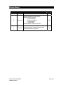
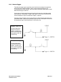
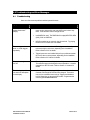
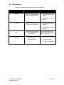
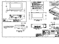
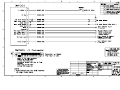
DMP-200 Digital Media Player
Installation Manual
Rev:
Date:
Doc Number:
C
07 Dec 2006
DMP8012-00
AVIONICS INNOVATIONS, INC.
2450 Montecito Road
Ramona, CA 92065
Phone (760) 788-2602
Fax (760) 789-7098
www.avionicsinnovations.com
Revision History
Revision
Date
A
26-July-06
Initial Release
B
20-Oct-06
Updated Installation Kit Part Numbers
Updates for V2.04 firmware
- PAUSE signal type
- BUSY active selection
- Test Ext Outputs
- Test Ext Inputs
Added Installation Checkout Procedure
SB
C
07-Dec-06
-Improved behavior of external Pause for better
operation with cabin PA Systems
SB
DMP-200 INSTALLATION MANUAL
P/N DMP8012-00 REV C
Description
By
SB
PAGE 2 OF 18
Table of Contents
REVISION HISTORY ....................................................................................................2
TABLE OF CONTENTS................................................................................................3
1.
INTRODUCTION..................................................................................................5
1.1
Description ........................................................................................................................................................ 5
1.2
Scope .................................................................................................................................................................. 5
1.3
Installation Kit.................................................................................................................................................. 5
2.0
MECHANICAL .....................................................................................................6
2.1
Specifications..................................................................................................................................................... 6
2.2
Mounting Considerations................................................................................................................................ 6
3.0
ELECTRICAL ......................................................................................................6
3.1
General............................................................................................................................................................... 6
3.2
Connection to Aircraft Power ........................................................................................................................ 6
3.3
Inputs ................................................................................................................................................................. 7
3.3.1
Remote Pause/Play Button........................................................................................................................ 7
3.3.2
Discrete Triggers ....................................................................................................................................... 8
3.3.3
Outputs....................................................................................................................................................... 9
3.3.4
Audio.......................................................................................................................................................... 9
3.3.5
Discrete ...................................................................................................................................................... 9
3.4
Connector Pinouts.......................................................................................................................................... 10
4.0
SETUP MODE ...................................................................................................11
4.1
Entering and Exiting Setup Mode ............................................................................................................... 11
4.1.1
Discrete Triggers 1 Through 3 – Active Level ...................................................................................... 11
4.1.2
External Pause – Active Level................................................................................................................ 11
4.1.3
External Chime Length ........................................................................................................................... 11
4.1.4
Display Brightness................................................................................................................................... 11
4.1.5
“LOUD” Volume Level.......................................................................................................................... 12
4.1.6
PLAY Screen Text .................................................................................................................................. 12
4.1.7
External Pause Signal Type .................................................................................................................... 12
4.1.8
Configuration of the BUSY Output........................................................................................................ 12
4.1.9
Test External Outputs.............................................................................................................................. 13
4.1.10
Test External Inputs................................................................................................................................. 13
DMP-200 INSTALLATION MANUAL
P/N DMP8012-00 REV C
PAGE 3 OF 18
5.0
INSTALLATION CHECKOUT PROCEDURE..................................................13
6.0
TROUBLESHOOTING AND ERROR MESSAGES ........................................14
6.1
Troubleshooting.............................................................................................................................................. 14
6.2
Error Messages............................................................................................................................................... 15
7.0
DRAWINGS .......................................................................................................16
7.1
Mechanical Drawing...................................................................................................................................... 16
7.2
Electrical Interconnect .................................................................................................................................. 16
DMP-200 INSTALLATION MANUAL
P/N DMP8012-00 REV C
PAGE 4 OF 18
1. Introduction
1.1
Description
The DMP-200 Digital Media Player is a self-contained unit which stores and replays prerecorded audio tracks. The audio tracks are encoded in “Motion Picture Expert Group
(MPEG) Level 3” format, commonly referred to as “MP3”. Audio files are stored in a
removable CompactFlash™ memory card which is prepared and installed by the user.
Audio tracks are selected via a single rotary pushbutton on the front panel of the
DMP-200. Optionally, the DMP-200 may be connected to a maximum of three external
discrete trigger inputs, each of which can be configured in software to select a particular
audio track.
The DMP-200 accepts a power input of between 10VDC and 35 VDC and provides a
single pair of ground-referenced stereo line-level audio output signals. A Mono output
which combines the Stereo line level outputs is also available.
The DMP-200 has been designed and tested to the Environmental Specifications of
RTCA DO-160E. An Environmental Qualification Form which describes the various
parameters and the levels to which they were tested is available upon request from
Avionics Innovations.
1.2
Scope
This document describes the installation and initial checkout of the DMP-200 Digital Media
Player. It may be used to support all installations, including those intended for initial Type
or Supplemental Type Certification approvals and FAA Form 337 Field Approvals.
1.3
Installation Kit
Before beginning the installation, verify that the following items are present:
Qty
Part No.
1
20000
Description
Digital Media Player Main Unit
1
DMP200-20
DMP-200 Installation Kit, consisting of:
1
DMP1010-00
(1ea) Mounting Tray
14046-00
(1ea) 16-pin Molex Connector
14400-00
(16ea) Molex Contacts
14073-00
DMP8012-00
(2ea) 4-40 X 3/8 Pan Head Screws
for Molex Connector
(1ea) 256MB CompactFlash™ Memory
Card
(1ea) DMP-200 Installation Guide
DMP8011-00
(1ea) DMP-200 Operators Guide
DMP200-01
(1ea) DMP200 Card Prep Software
DMP058
(OPTIONAL) USB reader/writer for
CompactFlash™ cards
DMP057
1
DMP-200 INSTALLATION MANUAL
P/N DMP8012-00 REV C
PAGE 5 OF 18
2.0 Mechanical
2.1
Specifications
The DMP-200 is fully contained within a 2-inch (5cm) high standard mount
enclosure.
Height:
Width:
Depth*:
Weight:
2.00 in.
6.25 in.
4.34 in.
1.10 lb
(5.1 cm)
(15.8 cm)
(11.0 cm)
(499 g) (With Mounting Tray)
Tray depth behind panel. Connector shell protrudes 0.25” (0.64 cm)
beyond system enclosure.
2.2
Mounting Considerations
The DMP-200 should be installed in a normally heated, pressurized section of the aircraft;
however the unit contains no moving parts and does not require special vibration isolation.
The unit may be mounted in an auxiliary area of the instrument panel, in a pedestal, or
anywhere in the aircraft cabin outside of the cockpit. In a severe vibration environment,
the unit should not be mounted vertically with the front panel facing down, to ensure that
the memory card does not accidentally vibrate loose. Otherwise, the DMP-200 may be
installed in any orientation and at any angle.
3.0 Electrical
3.1
General
The following guidelines should be used when installing the DMP-200:
♦
♦
♦
3.2
All wiring to be installed in accordance with FAA AC-4313-1A, Chapter 11, Sect. 2
All non-audio wiring to be MIL-W-22759 unless otherwise specified
All audio wiring to be MIL-C-27500 shielded unless otherwise specified
Connection to Aircraft Power
The DMP-200 accepts a wide range of input voltage directly, without the need for
converters or configuration changes.
Minimum input: 10.0 VDC
Maximum input: 35.0 VDC
(1.0 Amp @ 10.0 VDC)
(0.1 Amp @ 35 VDC)
Nominal input: 14 VDC / 0.30 Amp
28 VDC / 0.15 Amp
Aircraft power must be supplied via a 1 Amp resettable circuit breaker.
DMP-200 INSTALLATION MANUAL
P/N DMP8012-00 REV C
PAGE 6 OF 18
3.3
3.3.1
Inputs
Remote Pause/Play Button
An external input is provided which can either emulate the front panel pushbutton, or can
be used only to pause or resume playback. When set to “Edge-Activated”, the Remote
Pause/Play input going active will immediately pause or resume the playback of any
audio track in progress. In addition, if the knob has been turned so that a desired track is
displayed (i.e. “queued up”), activating the Remote Pause/Play input will cause the track to
begin playing. In these situations, the remote Pause/Play performs exactly like the front
panel pushbutton.
This is especially useful in single-pilot helicopter applications. If the remote pushbutton is
mounted on or near the cyclic, the pilot can control the audio without releasing the flight
controls. After playback of each audio track, the DMP-200 display automatically “points” to
the next track on the memory card. Thus, the pilot can simply press the remote button
after each track to initiate playback of the next audio track.
The Remote Pause/Play input can be configured in Setup Mode as active high or active
low. It can also be configured as either an “edge-activated” or a “level-activated” signal:
• Edge-Activated
When set to “edge-activated” (the default setting), the remote pushbutton works
exactly like the front panel knob. Pause/Play function is toggled each time the
signal changes from inactive to active, and new track playback may be started
from the remote pushbutton as well. For example, if set up as Active Low, the
Pause/Play will toggle each time a grounding pushbutton is pressed. Releasing
the button has no effect.
• Level-Activated
This setting is intended for use when the remote Pause/Play input is connected to
a cabin PA system’s KEY signal, to momentarily pause the DMP-200 playback
while the PA is in use. If a track is playing, the DMP-200 will be PAUSED for as
long as the Pause/Play signal is active, and will resume playing when the signal
returns to inactive. If the DMP-200 is either idle or paused when the remote
Pause/Play signal changes, it has no effect.
Like the discrete trigger inputs, Remote Pause/Play is floating and must be pulled up or
down with an external resistor, depending on the desired active state. The input signal
may vary between 0V and 35 VDC: levels above 3.5 VDC will be interpreted as “high”,
while levels below 3.5 VDC will be “low”.
When Edge-Activated is selected, the Remote Pause/Play input works in parallel with the
front panel knob – playback may be paused via one and resumed via the other. Unlike
the front panel knob, however, playback mode cannot be cancelled by holding the Remote
Pause/Play input active.
Like the discrete trigger inputs, Remote Pause/Play is floating and must be pulled up or
down with an external resistor, depending on the desired active state. The input signal
may vary between 0V and 35 VDC: levels above 3.5 VDC will be interpreted as “high”,
while levels below 3.5 VDC will be “low”.
The Remote Pause/Play input works in parallel with the front panel knob – playback may
be paused via one and resumed via the other. Unlike the front panel knob, however,
playback mode cannot be cancelled by holding the Remote Pause/Play input active.
DMP-200 INSTALLATION MANUAL
P/N DMP8012-00 REV C
PAGE 7 OF 18
3.3.2
Discrete Triggers
Three discrete trigger inputs are provided, each of which can be assigned to a particular
audio track via the CardPrep software. When a trigger input becomes active, the
corresponding audio track is played. Each input can be configured independently in Setup
Mode as active high or active low.
If more than one trigger input becomes active at the exact same time, the higher number
input has priority. For example, if Trigger 3 and Trigger 1 become active simultaneously,
the track assigned to Trigger 3 is played and Trigger 1 is ignored.
The trigger inputs are floating, and must be pulled up or down externally depending on the
desired active state. Inputs may vary between 0V and 35 VDC: levels above 3.5 VDC will
be interpreted as “high”, while levels below 3.5 VDC will be “low”.
Example: Active Low
The annunciator lamp
functions as a pull-up
resistor. If a lamp is not
used, it must be replaced
by a resistor (1/4 W, 10K
to 47K Ohms)
Example: Active High
The annunciator lamp
functions as a pull-down
resistor. If a lamp is not
used, it must be replaced
by a resistor (1/4 W, 10K
to 47K Ohms).
DMP-200 INSTALLATION MANUAL
P/N DMP8012-00 REV C
PAGE 8 OF 18
3.3.3
Outputs
3.3.4
Audio
The DMP-200’s stereo audio and mono outputs are ground-referenced, line-level signals
with a typical signal level of 1.8 V p-p. If isolation is required, an audio isolation
transformer such as a Triad SP-50 or a Magna-Tek TY-141P must be provided externally.
Volume level is selected from the front panel by the user, and stereo balance is selectable
from setup mode.
3.3.5
Discrete
Two discrete outputs are provided for interfacing external equipment: CHIME and BUSY.
CHIME is provided for interfacing to an external chime tone generator. CHIME is an opencollector output capable of sinking 1 Amp, with a maximum input voltage of 35 VDC.
CHIME goes active when a speech track has been selected or triggered, but the actual
playback does not begin until CHIME goes inactive. The length of time CHIME remains
active is selected in Setup Mode. CHIME can be used to enable an external chime or
tone generator, to annunciate the fact that a speech message is about to begin. CHIME
does not go active when a music track has been selected.
By default, BUSY is active anytime the DMP-100 is producing audio. However, the
installer may configure BUSY to go active only for speech tracks, only for music tracks, for
all types of tracks, or even to never go active at all. BUSY can be used to drive an audio
switching relay, enable an external amplifier, or even to light a remote annunciator. This
selection is done in SETUP mode.
DMP-200 INSTALLATION MANUAL
P/N DMP8012-00 REV C
PAGE 9 OF 18
3.4
Connector Pinouts
Pin
Name
1
PWR
Aircraft power, 10-35 VDC
2
AUDL
Audio output, left channel
3
SPARE1
4
TRIG3
External trigger input 3
5
TRIG2
External trigger input 2
6
TRIG1
External trigger input 1
7
AUDR
Audio output, right channel
8
PWR
Aircraft power, 10-35 VDC
A
Reserved
B
PAUSE
External PAUSE/PLAY input
C
AGND
Audio Ground
D
AGND
Audio Ground
E
BUSY
BUSY output, open collector, 0.5A max
F
CHIME
CHIME output, open collector, 1A max
H
MONO
Mono Audio Output
J
GND
Aircraft power return
DMP-200 INSTALLATION MANUAL
P/N DMP8012-00 REV C
Description
Reserved
Not Used
PAGE 10 OF 18
4.0 Setup Mode
4.1
Entering and Exiting Setup Mode
Setup Mode is entered via the following steps:
1. Turn the unit off.
2. Depress and hold the front panel knob.
3. Switch the unit on while continuing to hold in the front panel knob.
4. Release the knob when the display first lights up. After the 5-second intro
screen, the first Setup Mode item is displayed.
Setup Mode is exited by simply cycling power on the unit.
Turning the knob once Setup Mode has been entered allows selection of the following
setup items:
4.1.1
Discrete Triggers 1 Through 3 – Active Level
The current active level of each of the three discrete triggers, TRIG1 through TRIG3 is
displayed. Pushing the front panel knob toggles each between “ACTIVE HIGH” and
“ACTIVE LOW”. The new settings are immediately written to permanent memory – no
explicit “save” action is required.
4.1.2
External Pause – Active Level
The current active level of each of the external PAUSE input is displayed. Pushing the
front panel knob toggles each between “ACTIVE HIGH” and “ACTIVE LOW”. The new
setting is immediately written to permanent memory – no explicit “save” action is required.
4.1.3
External Chime Length
The CardPrep software offers the user the option of activating an external chime prior to
playing a speech track. The “EXT CHIME LENGTH” setup item determines how long the
unit waits, with the CHIME signal asserted, before de-asserting the CHIME signal and
playing the speech track. Pushing the front panel knob cycles EXT CHIME LENGTH from
0 to 9 seconds.
CardPrep also offers the option of an “internal” chime, which is simply a selected MP3 file
(usually a recording of a chime of some type) that is played before each speech track.
Note that if a card specifies an internal chime, the CHIME output is not activated.
4.1.4
Display Brightness
The DMP-200’s display can be set to one of eight brightness levels. Each push of the
front panel knob cycles through a brightness level between 12.5% and 100%. Set this to
a level appropriate to the expected cockpit lighting conditions.
DMP-200 INSTALLATION MANUAL
P/N DMP8012-00 REV C
PAGE 11 OF 18
4.1.5
“LOUD” Volume Level
The playback volume level is normally set by turning the front panel knob while holding the
knob pushed in. However, the CardPrep software allows the user to designate any track
to be played at a “LOUD” volume setting. This is normally applied to speech tracks such
as important safety messages. For example, if the DMP-200 is playing background music
and the operator has set the volume to an unobtrusive level, the safety message can be
played at a higher volume and the previous volume level will be restored when the music
resumes.
This setup item allows you to select the volume level which will be set if a track is played
which has the “LOUD” volume attribute enabled. Pressing the front panel knob will start
playback of a sample speech track, which loops continuously. Turning the knob will adjust
(and display) the volume setting which will then be retained as the “LOUD” volume level.
The “LOUD” volume setting is also used when an internal chime is played.
4.1.6
PLAY Screen Text
The DMP-200 can display one of two types of screens while an audio track is playing.
The default is an elapsed time display which shows the length of time the track has been
playing. The second type of display is “Prompts” which cycle through helpful suggestions
of user interface options. Each push of the front panel knob toggles between the
selections of each type of display.
4.1.7
External Pause Signal Type
The external Play/Pause input signal can be treated as either an “EDGE” or a “LEVEL”. If
“EDGE“ is selected, the play/pause function will toggle each time the external button is
pressed-and-released. If “LEVEL” is selected, the DMP-200 will remain paused as long
as the external button is held down, and will resume when the button is released.
Press the button to toggle between “EDGE” and “LEVEL”. The factory default value is
“EDGE”.
4.1.8
Configuration of the BUSY Output
The BUSY Output can be configured to go active under one of the following conditions:
•
Any time a SPEECH track is playing
•
Any time a MUSIC track is playing
•
Any time a track is playing, regardless of the track type (factory default value)
•
BUSY never goes active
Press the button to cycle through these choices. When the desired choice is displayed,
simply cycle power to the DMP-200 or select a different SETUP category.
DMP-200 INSTALLATION MANUAL
P/N DMP8012-00 REV C
PAGE 12 OF 18
4.1.9
Test External Outputs
This page allows the installer to cycle through all the DMP-200 external outputs, setting
and clearing each one in turn. This function is used during the installation checkout
procedure, and may be used any time an external output needs to be tested. Each press
of the button will activate one output and clear all others. Except the “All OFF” selection,
which turns off all outputs.
4.1.10 Test External Inputs
This page allows the installer to test the three external trigger inputs and the external
Play/Pause input. The display shows which input, if any, is currently active. If more than
one input is active, the display will show only the highest priority input. Play/Pause is the
highest priority, followed Triggers 3 through 1 in descending order.
If an input appears to have the wrong polarity, be sure the active levels are set correctly
(see page 11 for more information on setting active levels for inputs).
5.0 Installation Checkout Procedure
After all wiring is double-checked, especially the power and ground connections, the following
procedure should be performed to verify external connections:
1. Press and hold the button while turning on power. Release the button when the DMP-200
display first lights up.
2. The DMP-200 will be in SETUP mode. Advance through all the setup items as described
above, and set the options to match your installation. Do NOT select the setup item: “Set
LOUD volume level” unless you have a memory card installed that has been prepared
using the supplied CardPrep software.
3. Turn the knob to display the SETUP item labeled “Test Ext Outputs”. Press the button
repeatedly to cycle through the various external outputs. Confirm that all attached
equipment (annunciators, relays, chime generators, etc) perform as intended.
4. Turn the knob to display the SETUP item labeled “Text Ext Inputs”. For each input
(triggers and external Pause/Play), activate the external contact closure and confirm the
corresponding display on the DMP-200.
To verify the audio outputs, you must prepare a memory card using CardPrep software before
powering up the DMP-200. Power up the DMP-200 normally (do not enter SETUP mode), and
select a track for playback to create an audio signal for testing.
DMP-200 INSTALLATION MANUAL
P/N DMP8012-00 REV C
PAGE 13 OF 18
6.0 Troubleshooting and Error Messages
6.1
Troubleshooting
Here are a few common problems and their potential causes:
Symptom
Possible Causes/Solutions
•
Volume turned down. Last volume setting is retained between
power cycles, and previous user may have turned volume way
down. Push-and-turn knob to change volume.
•
Invalid MP3 file used. The DMP200 will not play MP3-PRO, MP4
(AAC), WAV or WMF files.
•
MP3 file recorded at an extremely low volume level. Try playing
the file on a PC to make sure it is audible.
•
Incorrect active levels selected. Each trigger must be configured
to be active high or active low, depending on the installation.
Refer to Section 3.3.2 for details.
•
Trigger inputs were not installed with pull-up or pull-down resistor.
One or the other must be present, depending on the installation.
Refer to Section 3.3.2 above for details.
Display is too bright or
too dim.
•
The display is set to one of eight levels of brightness at installation.
This selection cannot be changed in normal operation. It must be
changed from SETUP mode. Refer to Section 4.1.4 above for
details.
Tracks being played do
not match the description
on the display.
•
In CardPrep, “Update Settings Only” was selected on the Create
Card tab even though MP3 tracks were changed. This button
may only be used when items such as Triggers and Attributes
have changed, but not the actual MP3 tracks. Regenerate the
card using the Create Card button.
No audio, even though
display shows track
playing.
External triggers do not
work, or a track triggers
repeatedly.
DMP-200 INSTALLATION MANUAL
P/N DMP8012-00 REV C
PAGE 14 OF 18
6.2
Error Messages
In addition, the DMP-200 may display the following error messages:
Display
Meaning
Invalid Card, no
firmware.
The firmware update file,
“0000.hex”, cannot be opened
on the CompactFlash card.
Invalid Card, no MP3
config.
The MP3 configuration file,
“0000.xd3”, cannot be opened
on the CompactFlash card.
Internal error number
XX
A fault has occurred between
the two internal processors of
the DMP200.
Memory Card Not
Inserted!
The DMP200 is not detecting
the presence of a
CompactFlash card.
DMP-200 INSTALLATION MANUAL
P/N DMP8012-00 REV C
Possible Causes
•
The card was not prepared
using DMP200 CardPrep
software
•
The card was created for a
DMP100
•
The card was not prepared
using DMP200 CardPrep
software
•
The card was created for a
DMP100
Contact Avionics Innovations.
Please record the error number
shown on the display.
•
No card is inserted
•
The card is defective
•
The card is not fully seated
PAGE 15 OF 18
7.0 Drawings
7.1
Mechanical Drawing
7.2
Electrical Interconnect
DMP-200 INSTALLATION MANUAL
P/N DMP8012-00 REV C
PAGE 16 OF 18