1
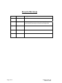
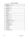
I.C.E. Integrated Cabin Entertainment System Installation Manual Avionics Innovations 2450 Montecito Road Ramona, CA 92065 Phone (760) 788-2602 Fax (760) 789-7098 P/N 8010-00, Revision B March 28, 2008 Intentionally Left Blank Page 2 of 16 ICE8010-00, Rev B March 28, 2008 Record of Revisions Revision Revision Date Description A 10 March 2006 Intial Release B 28 March 2008 Revised Drawings for DVD & Video Amp. Added I/R Remote Sensor Install Kit, Drawings for I/R Sensor and Light Guide. Page 3 of 16 ICE8010-00, Rev B March 28, 2008 Table of Contents 1. General Information..................................................................................................................................5 1.1. General Description..................................................................................................................................5 1.2. Unpacking and Inspecting the ICE System............................................................................................5 1.3. Specifications ............................................................................................................................................6 1.3.1. PCU, Passenger Control Unit ................................................................................................................6 1.3.2. DVD/CD Player .....................................................................................................................................6 1.3.3. Remote Satellite Radio Module .............................................................................................................7 1.3.4. Video Amplifier .....................................................................................................................................7 1.4. Installation Accessories ............................................................................................................................8 1.4.1. PCU, Passenger Control Unit ................................................................................................................8 1.4.2. DVD/CD Player .....................................................................................................................................8 1.4.3. Remote Satellite Radio Module .............................................................................................................8 1.4.4. Video Amplifier .....................................................................................................................................8 1.4.5. IR Remote Sensor Assy .........................................................................................................................8 1.4.6. Items Not Provided ................................................................................................................................8 1.4.7. Crimp Tools ...........................................................................................................................................9 1.4.8. Warranty ................................................................................................................................................9 1.5. Rear Connections ...................................................................................................................................10 1.5.1. PCU, Passenger Control Unit ..............................................................................................................10 1.5.2. DVD/CD Player ...................................................................................................................................11 1.5.3. Remote Satellite Radio Module ...........................................................................................................12 1.5.4. Video Amplifier ...................................................................................................................................13 1.6. Installation ..............................................................................................................................................14 1.6.1. PCU, Passenger Control Unit ..............................................................................................................14 1.6.2. DVD/CD Player ...................................................................................................................................14 1.6.3. Remote Satellite Radio Module ...........................................................................................................14 1.6.4. Antenna................................................................................................................................................14 1.6.5. Video Amplifier ...................................................................................................................................14 1.7. Post Installation Checkout .....................................................................................................................15 1.7.1. Post installation procedures all Units...................................................................................................15 1.7.2. PCU, DVD/CD & Remote Satellite Radio Module .............................................................................15 1.7.3. Video Amplifier ...................................................................................................................................15 1.8. Drawings, Mechanical & Interconnect .................................................................................................16 1.8.1. PCU Mechanical ..................................................................................................................................16 1.8.2. DVD/CD Mechanical ..........................................................................................................................16 1.8.3. Satellite Remote Receiver Mechanical ................................................................................................16 1.8.4. Video Amplifier Mechanical ...............................................................................................................16 1.8.5. Satellite Antenna Mechanical ..............................................................................................................16 1.8.6. I/R Sensor & Light Guide Mechanical ................................................................................................16 1.8.7. Light Guide Mechanical ......................................................................................................................16 1.8.8. ICE Block Diagram .............................................................................................................................16 1.8.9. PCU Control Head ...............................................................................................................................16 1.8.10. DVD/CD Player ...................................................................................................................................16 1.8.11. Satellite Remote Receiver ....................................................................................................................16 1.8.12. Video Amplifier ...................................................................................................................................16 1.8.13. Video Amplifier ...................................................................................................................................16 1.8.14. PCU & DVD Interconnect ...................................................................................................................16 1.8.15. PCU & Satellite Interconnect ..............................................................................................................16 1.8.16. PCU, DVD & Satellite Interconnect ....................................................................................................16 Page 4 of 16 ICE8010-00, Rev B March 28, 2008 1. General Information The purpose of this operation manual is to provide information to ensure proper installation of this product. It is the responsibility of those installing this item on or within a specific type or class of certified aircraft to document and obtain approval for an acceptable installation from the administrator. 1.1. General Description The ICE system consists of four main components: Passenger Control Unit (PCU) DVD/CD Player (DVD) Remote Satellite receiver (SAT) Video Amplifier The PCU will normally be mounted in an area accessible to the passengers. PCU with IR remote controls remote mounted “I.C.E.” components: Sirius© Satellite Radio, DVD/CD, and AUX audio input. Two distinct channels allow some passengers to receive one source while others receive a second source. All of the functions can be operated from the PCU. There is an infrared remote controller that can control the most frequently used functions such as volume, etc. The SAT is remote mounted Sirius© Satellite Radio module with antenna. Sirius provides 120 streams of coast–tocoast digital quality sound including NFL and NASCAR. There are no passenger controls on the SAT unit. The DVD/CD player is a remote mounted multi-regional DVD drive which allows you to view DVDs or listen to CD’s. The unit also is a CD/MP3 player. DVD/CD player should be mounted in an area that passengers have access to for changing discs. This can be in a cabinet or entertainment equipment bay. The only direct passenger operation on the DVD is “Eject” when the PCU is off. When the system is on, the eject feature is controlled at the PCU. AI - Video Amp is a remote mounted video amp with 2 video inputs and 6 video outputs. Each of the 6 video outputs is selected between Video 1 or 2 input. Six individual 12 VDC power supplies at 0.75 amps each. 1.2. Unpacking and Inspecting the ICE System Exercise extreme care when unpacking the ICE System. Make a visual inspection of the unit for evidence of damage incurred during shipment. If a claim for damage is to be made, the unit must be returned in the original packaging. Page 5 of 16 ICE8010-00, Rev B March 28, 2008 1.3. Specifications 1.3.1. PCU, Passenger Control Unit SPECIFICATION Part Number Operating Voltage Current Draw Remote Weight Physical Dimensions CHARACTERISTIC PCU20-00 11-33 VDC 0.2 Amps Infrared Red 3 Wire 0.75 LBS (.34KG) Unit Length: 1.25” (32mm) Note: With Knob Unit Width: 5.50” (140mm) Unit Height: 2.00” (59mm) 1.3.2. DVD/CD Player SPECIFICATION Part Number Operating Voltage Current Draw DVD Playable Discs Audio Output Audio Frequency Response Audio Input Weight Physical Dimensions Page 6 of 16 CHARACTERISTIC AV5008-00 11-33 VDC 0.4 Amps DVD, CD & MP3 Mutli Region & All Video Output: NTSC or Pal 5 Volts RMS into 30 Ohm Load 100Hz to 20Khz Nominal (2ea) Aux Audio Inputs Audio Input Impedance: Greater Than 10K Aux Audio Input Sensitivity: 200mV 1.70 LBS (.34KG) Unit Length: 8.75” (222mm) W/Connectors Unit Width: 5.80” (148mm) Unit Height: 1.80” (46mm) ICE8010-00, Rev B March 28, 2008 1.3.3. Remote Satellite Radio Module SPECIFICATION Part Number Operating Voltage Current Draw Satellite Radio Audio Output Audio Frequency Response Audio Input Weight Physical Dimensions CHARACTERISTIC SSR30-00 11-33 VDC 0.2 Amps Receiving Frequencies: 2322.293/2330.207 MHz Audio: Signal to Noise Ratio: 95db Distortion: 0.01 % (1 kHz) 5 Volts RMS into 30 Ohm Load 100Hz to 20Khz Nominal (2ea) Aux Audio Inputs Audio Input Impedance: Greater Than 10K Aux Audio Input Sensitivity: 200mV 1.20 LBS (.34KG) Unit Length: 6.25” (159mm) Unit Width: 5.00” (127m) Unit Height: 1.25” (32mm) 1.3.4. Video Amplifier SPECIFICATION Part Number Operating Voltage Current Draw Video Format Video Input Video Output Level Video Output Output Impedance Discrete Inputs Input Sources Weight Physical Dimensions Page 7 of 16 CHARACTERISTIC AV2016-00 18-33 VDC 2.5 Amps NTSC or Pal Video Input Level: 1.0Vpp Video Output Level: 1.0 Vpp Video Output: Six Channels Output Impedance 75 Ohms (6ea) Discrete Inputs, Logic Level Low or Momentary Switch Input. Selects between Video 1 & Video 2 for each of the Six Video Outputs. Two Channels 1.00 LBS (.34KG) Unit Length: 6.25” (159mm) Unit Width: 2.00” (51mm) Unit Height: 1.75” (44mm) ICE8010-00, Rev B March 28, 2008 1.4. Installation Accessories 1.4.1. PCU, Passenger Control Unit P/N PCU20-01, PCU Installation Kit (1ea) ICE8011-00 ICE User Manual (1ea) 15 Pin D-Sub Female Mating Connector (1ea) 15 Pin Backshell (15ea) D-Sub Female Pins (1ea) Remote Control Unit 1.4.2. DVD/CD Player P/N AV5008-01, DVD/CD Player Installation Kit (1ea) 25 Pin D-Sub Female Mating Connector (1ea) 25 Pin D-Sub Backshell (25ea) D-Sub Female Pins 1.4.3. Remote Satellite Radio Module P/N SSR30-01, Satellite Radio Installation Kit (1ea) 25 Pin D-Sub Female Mating Connector (1ea) 25 Pin D-Sub Backshell (25ea) D-Sub Female Pins (1ea) Sirius Radio Antenna Mechanical: Weight: 0.7 Oz Height: 73 Inch Diameter: 3.50 Inches Finish: Skydrol Resistant Polyurethane Enamel Material: ALUM 6061-T6, Thermoset Plastic Connector: Type “TNC” Female 1.4.4. Video Amplifier P/N AV2016-01, Video Amplifier Installation Kit (1ea) 26 Pin HD Male Mating Connector (1ea) 26 Pin Backshell (26ea) HD Male Pins 1.4.5. IR Remote Sensor Assy P/N IRR020-01 (1ea) 3 Pin Molex (3ea) Female Pins (1ea) Light Guide 1.4.6. Items Not Provided Video Connectors and Antenna Connector All Cables and Wiring Mounting Hardware Page 8 of 16 ICE8010-00, Rev B March 28, 2008 1.4.7. Crimp Tools AMP P/N Daniels P/N Recommended Crimp Tools High Density 22-28 AWG Ha n d Positioner Insertion/ Crimping Extraction Tool Tool M22520/2-01 M22520/2-09 M81969/1-04 9507 9 5 0 2 -3 M81969/1-04 9 9 5 -0 0 0 1 995-0001-739 N/A 584 6 0 1 9 6 6 -1 6 0 1 9 6 6 -6 9 1 0 6 7 -1 AFM8 K42 M24308/18-1 Astro P/N 615717 Military P/N Positronic P/N ITT Cannon P/N 615725 M81969/1-02 Standard Density 20-24 AWG Positioner Insertion/ Extraction Tool M22520/2-08 M81969/1-02 9 5 0 2 -5 M81969/1-02 9 8 0 -2 0 0 0 -4 2 6 9 9 5 -00 0 1 -6 0 4 6 0 1 9 6 6 -5 K1 3 -1 615724 91067-2 M24308/1-02 8 M81969/1-02 1.4.8. Warranty Avionics Innovations warrants the ICE System against material or manufacturing defects for a period of one year from the date of installation. Avionics Innovations will, upon receipt of the failed unit, repair or replace the unit at our discretion. Avionics Innovations will pay UPS Ground shipping charges for warranty returned items. Charges for express shipment will be the responsibility of the sender. This warranty will be void if the unit has been tampered with or opened by unauthorized personnel. To validate warranty you must return completed AEA Warranty Form This warranty is not transferable. Any implied warranties expire at the expiration date of this warranty. WE SHALL NOT BE LIABLE FOR INCIDENTAL OR CONSEQUENTIAL DAMAGES. This warranty does not cover a defect that has resulted from improper or unreasonable use or maintenance as determined by us. This warranty is void if there is any attempt to disassemble this product without factory authorization. During the warranty period, the unit must be returned to Avionics Innovations and, at own option, will be repaired or replaced at no charge. IMPORTANT: Any labor charges associated with the removal of product or related trouble shooting by any firm other than Avionics Innovations will not be covered. NOTE FOR TECHNICAL ASSISTANCE PLEASE CALL 760-788-2602 8:00 AM TO 5:00 PM PST. ALL REPAIRS AND RETURNS ARE PROCESSED THROUGH AVIONICS INNOVATIONS. Email: [email protected] Page 9 of 16 ICE8010-00, Rev B March 28, 2008 1.5. Rear Connections 1.5.1. PCU, Passenger Control Unit J1 (15 Pin Male) 1 Passenger Control Unit 2 Power Ground 3 Satellite RS 232 TX 4 Satellite RS 232 RX 5 RS 232 Com 6 DVD RS 232 TX 7 DVD RS 232 RX 8 RS 232 Com 9 SDA Audio Control Output 10 SCL Audio Control Output 11 Infrared Red RX Input 12 Infrared Ground 13 Infrared Red 3.3 VDC Power Output 14 Spare 15 Spare Page 10 of 16 1 1 -3 3 VDC In ICE8010-00, Rev B March 28, 2008 1.5.2. DVD/CD Player J -3 (25 Pin Male) 1 DVD/CD 2 RS232 TX 3 RS232 RX 4 Power Ground 5 Audio Ground 6 Audio Ground 7 Audio Ground 8 Left Audio Pre-Amp Output 9 Right Audio Pre-Amp Output 10 SDA Audio Control Input 11 SCL Audio Control Input 12 +28VDC Mute In 13 Ground Mute In 14 1 1 -3 3 VDC In 15 Left Secondary Headphone Output 16 Right Secondary Headphone Output 17 Left Main Headphone Output 18 Right Main Headphone Output 19 #2 Aux Audio In Left 20 #2 Aux Audio In Right 21 Audio Mute Input 22 Power Ground 23 Power Ground 24 #1 Aux Audio In Left 25 #1 Aux Audio In Right Page 11 of 16 Power Ground ICE8010-00, Rev B March 28, 2008 1.5.3. Remote Satellite Radio Module J2 (25 Pin Male) 1 Satellite Radio 2 Left Secondary Headphone Output 3 Audio Ground 4 Right Secondary Headphone Output 5 Power Ground 6 #1 Aux Audio In Left 7 Audio Ground 8 #1 Aux Audio In Right 9 RS 232 TX 10 Spare 11 SCL Audio Control Input 12 Spare 13 Satellite Left Audio Pre-Amp Output 14 Spare 15 Spare 16 Gro u n d 17 1 1 -3 3 VDC In 18 Ground Mute In 19 #2 Aux Audio In Left 20 RS232 RX 21 #2 1 Aux Audio In Right 22 Right Main Headphone Output 23 Left Main Headphone Output 24 Satellite Right Audio Pre-Amp Output 25 SDA Audio Control Input Page 12 of 16 +28VDC Mute In ICE8010-00, Rev B March 28, 2008 1.5.4. Video Amplifier J7 (26 Pin Female) 1 Video Amplifier 2 Video 2 Control In 3 Video 3 Control In 4 Video 4 Control In 5 Video 5 Control In 6 Video 6 Control In 7 Video Switch Select (Open for Momentary and GND for Direct Switch) 8 18-33 VDC In for 12VDC Outputs on Pins 19-24 9 18-33 VDC In for 12VDC Outputs on Pins 19-24 10 Video 1 Control Gnd 11 Video 2 Control Gnd 12 Video 3 Control Gnd 13 Video 4 Control Gnd 14 Video 5 Control Gnd 15 Video 6 Control Gnd 16 Gro u n d 17 Power Ground 18 Power Ground 19 #1 + 12 VDC Output 20 #2 + 12 VDC Output 21 #3 + 12 VDC Output 22 #4 + 12 VDC Output 23 #5 + 12 VDC Output 24 #6 + 12 VDC Output 25 18 to 33VDC Input for Video Output 26 18 to 33VDC Input for Video Output Page 13 of 16 Video 1 Control In ICE8010-00, Rev B March 28, 2008 1.6. Installation 1.6.1. PCU, Passenger Control Unit Select location in cabin for mounting, see mechanical drawings for dimensions of unit. Mount tray in location using AN 6/32 hardware. Wire the unit as per attached diagram. 1.6.2. DVD/CD Player Select location in cabin for mounting, see mechanical drawings for dimensions of unit. Mount tray in location using AN 6/32 hardware. Wire the unit as per attached diagram. NOTE: Unit can be mounted Horizontal or Vertical 1.6.3. Remote Satellite Radio Module Select an appropriate location in the aircraft, see mechanical drawings for dimensions of unit. Mount tray in location using AN 6/32 hardware. Wire the unit as per attached diagram. 1.6.4. Antenna Install antenna on top of aircraft using approved practices and data. Ensure the antenna is well bonded Resistance between antenna and mating surface to be less than 10mΩ. Use RG 142 for antenna lead, limit coax length to 25ft. The Antenna will need a clear view of the Northern Sky for proper reception. The AI-SSR will not operate inside the hangar, and in some instances next to tall hangars that obstruct the view of the Satellite to the Antenna. 1.6.5. Video Amplifier Select location in cabin for mounting. Mount tray in location using AN 6/32 hardware. Wire the unit as per attached diagram. Page 14 of 16 ICE8010-00, Rev B March 28, 2008 1.7. Post Installation Checkout 1.7.1. Post installation procedures all Units 1. Prior to power-up, review correct wiring by using VOM. 2. Check Power Input and Verify all Grounds. 1.7.2. PCU, DVD/CD & Remote Satellite Radio Module Press the PCU “PWR”, this switch turns the power on to the PCU. Press the “SRC” and verify the unit switches from SAT to DVD to AUX. PCU will only display units connected to the PCU. Using the Rotary/Pushbutton increase the audio out and verify that audio is heard on all SAT, DVD and AUX. The PCU will display channel 184 when the Sirius Satellite is selected. No other channels will be selectable until the satellite radio is subscribed. NOTE This unit requires a subscription service from Sirius Satellite Radio. The service can be obtained by contacting Sirius Satellite Radio @ 1-888-539-7474 or on the web www.sirius.com Information needed to start subscription will be aircraft make and model, owners address, credit card information for monthly billing and the Sirius ID # located on the back panel of the AI-SSR unit. 1.7.3. Video Amplifier Turn on power and verify power & video out on installed video monitors. If Video ½ switches are installed, verify proper operation Page 15 of 16 ICE8010-00, Rev B March 28, 2008 1.8. Drawings, Mechanical & Interconnect 1.8.1. PCU Mechanical 1.8.2. DVD/CD Mechanical 1.8.3. Satellite Remote Receiver Mechanical 1.8.4. Video Amplifier Mechanical 1.8.5. Satellite Antenna Mechanical 1.8.6. I/R Sensor & Light Guide Mechanical 1.8.7. Light Guide Mechanical 1.8.8. ICE Block Diagram 1.8.9. PCU Control Head 1.8.10. DVD/CD Player 1.8.11. Satellite Remote Receiver 1.8.12. Video Amplifier 1.8.13. Video Amplifier 1.8.14. PCU & DVD Interconnect 1.8.15. PCU & Satellite Interconnect 1.8.16. PCU, DVD & Satellite Interconnect Page 16 of 16 ICE8010-00, Rev B March 28, 2008 5 4 3 2 1 REV. A REVISIONS DESCRIPTION INITIAL RELEASE DATE 3-10-06 APPRVD Sirius Sat Antenna P/N S67-1575-65 IPOD D D (MP3 Player Jack) Sat Radio Module 28VDC Avionics Buss (1.0 Amp CB) GND P/N SSR30-00 Aux Entertainment Input (Sirius) Audio Out Left & Right RS232 Control (Optional) NOTE: Each Audio Channel can select between DVD/CD, Sirius Satellite and Aux Input, with independent volumne controls. Audio Input C Handheld Remote C AI-PCU P/N PCU20-00 Main Audio Channel Out (Passenger Control Unit) 28VDC Avionics Buss (0.5 Amp CB) GND Secondary Audio Channel #2 Out PA Mute (Mutes only the Main Audio Channel) #1 Display #2 Video Source Video Output #2 Display B RS232 Control Audio Out Left & Right AI-DVD/CD 28VDC Avionics Buss (3 Amp CB) P/N AV5008-00 #2 Video Source #1 AI-Video Video Source Amplifier Input Video Output #3 Display #4 Display P/N AV2016-00 (Multi Regional & Single Disk) GND B #5 Display 28VDC Avionics Buss (5 Amp CB) A #6 Display A GND "ICE" Integrated Cabin Entertainment DRAWN CHECKED DATE 01-30-06 TITLE DATE APPROVED DATE M Mahan I.C.E. Functional Block Diagram SIZE ISSUED DATE DRAWING NO. 4 3 2 A ICE 8010-6 FILE NAME: TL DWG ICE8001 5 REV SHEET 1 8 OF 16 5 4 3 2 1 REV. A REVISIONS DESCRIPTION INITIAL RELEASE DATE 3-10-06 APPRVD D D PCU Pigtail (Provided with Unit) P/N PCU20-00 +11-33VDC Input C J1 15 Pin (Female) 0.5 AMP 1 +11VDC-33VDC Power Gnd 2 SAT RS232 TX SAT RS232 RX RS232 COM 3 4 5 To Sat Remote DVD 232 TX DVD 232 RX 6 7 8 To DVD SAT/DVD SDA SAT/DVD SCL 9 10 } 11 12 13 IR TX IR Gnd IR 3.3VDC 3 2 1 C To PCU (See Note 1) White Black Remote I/R Sensor Red B B 3-Pin Connector Avionics Innovations A Category 5 4 3 2 ICE Interconnect Title PCU Control Head Size B Document Number Create: A Rev ICE 8010-7 A Mod: Sheet 9 1 of 16 5 4 DVD/CD P/N AV5008-00 +28V In C Left Main Phone Out Right Main Phone Out Audio Gnd 17 18 5 Left Secondary Phone Out Right Secondary Phone Out Audio Gnd 15 16 6 #1 Aux Audio In Left #1 Aux Audio In Right Audio Gnd #2 Aux Audio In Left #2 Aux Audio In Right 24 25 7 19 20 Left PreAmp Audio Out Right PreAmp Audio Out 8 9 232 RX 232 TX Ground 3 2 22 SDA Input SCL Input Ground + 28VDC Mute Relay In GND Mute Relay Input B PA Mute Input 1 REV. A B REVISIONS DESCRIPTION INITIAL RELEASE Added PA Mute Input on Pin 21 DATE 3-10-06 3-20-08 APPRVD 3 AMP 14 4 1 Audio Control { 2 J3 25 Pin Power Gnd Power Gnd D 3 +11VDC-33VDC D } } Passenger Main Cockpit Secondary NOTE: The secondary output does not mute with the External mute system. Sat Remote or AUX Audio Input C AUX Audio Input } Low Level Output (For Sat Remote #1Aux Audio Input Only) To PCU 10 11 23 12 13 } 21 } To PCU (See Note 1) B } Aircraft Audio Mute System Control Connected Audio High of Aircraft PA Speaker Note 1: Audio Control Wire SDA/SCL connected to either DVD or SAT Remote. Do Not Connect to Both or Parallel Avionics Innovations A Category 5 4 3 2 ICE Interconnect Title DVD/CD Player Size B Document Number Create: A Rev ICE 8010-8 B Mod: Sheet 10 of 16 1 5 4 3 2 1 REV. A REVISIONS DESCRIPTION INITIAL RELEASE DATE 3-10-06 APPRVD Satellite Remote Receiver D P/N SSR30-00 +28V In Power Gnd J2 1 AMP 17 +11VDC-33VDC 5 Left Main Phone Out 23 Right Main Phone Out 22 Audio Gnd 3 Left Secondary Phone Out Right Secondary Phone Out C } } 2 4 #1 Aux Audio In Left #1 Aux Audio In Right Audio Gnd #2 Aux Audio In Left #2 Aux Audio In Right 6 8 7 19 21 Left PreAmp Audio Out Right PreAmp Audio Out 13 24 RS232 TX RS232 RX Ground 9 20 16 SDA Input SCL Input 25 11 Audio Control { D Passenger Main Cockpit Secondary NOTE: The secondary output does not mute with the External mute system. DVD or AUX Audio Input C AUX Audio Input } Low Level Output (For DVD #1Aux Audio Input Only) To PCU } To PCU (See Note 1) } Aircraft Audio Mute System Control B B + 28VDC Mute Relay In 1 GND Mute Relay Input 18 Spare Spare Spare Spare 10 12 14 15 Note 1: Audio Control Wire SDA/SCL connected to either DVD or SAT Remote. Do Not Connect to Both or Parallel Avionics Innovations A Category 5 4 3 2 ICE Interconnect Title Satellite Remote Receiver Size B Document Number Create: A Rev ICE 8010-9 A Mod: Sheet 11 of 16 1 5 Video Amplifier D C 4 3 2 REV. A B Power Gnd Power Gnd Video 1 Control In Video 1 Control Gnd 17 18 1 10 Video 2 Control In Video 2 Control Gnd 2 11 Video 3 Control In Video 3 Control Gnd 3 12 Video 4 Control In Video 4 Control Gnd 4 13 Video 5 Control In Video 5 Control Gnd 5 14 Video 6 Control In Video 6 Control Gnd 6 15 Video Switch Select 7 +28V Power In +12VDC Out +28V Power In +12VDC Out 8 9 Video Amp 22AWG Momentary or SPST Switches D See Note 1: C (Open) for Momentary Switch Input (Ground) for direct Switch Input Video Amp 20AWG 19 #2 Video Monitor 20 21 #3 Video Monitor #4 +12VDC Out 22 #4 Video Monitor #5 +12VDC Out 23 #5 Video Monitor A Leave Pin 7 Open if you are using a momentary switch to select the Video 1 or 2. Avionics Innovations Category 3 2 A ICE Interconnect Title Video Amp Size B Document Number Create: 4 B Notes: 1. Ground pin 7 if you are using a toggle ON/OFF switch for selection of Video 1 or 2. #6 Video Monitor 24 +11VDC-33VDC 5 AMP #1 Video Monitor #3 +12VDC Out 5 +11VDC-33VDC 20AWG 1 AMP MAX 22AWG #6 +12VDC Out APPRVD 1 AMP B #2 +12VDC Out DATE 3-10-06 3-10-08 P7 P/N AV2016-00 26 HD (S/N 2000 & UP) +28V Power In Video 25 +28V Power In Video 26 #1 +12VDC Out 1 REVISIONS DESCRIPTION INITIAL RELEASE Changed Power Input and Added Switch Select Rev ICE 8010-10 Mod: B Sheet 12 of 16 1 5 4 3 2 1 REV. A REVISIONS DESCRIPTION INITIAL RELEASE DATE 3-10-06 APPRVD Video Amplifier P/N AV2016-00 IN 1 BNC M17/29-RG59 #1 Video Input D #1 Video Source D IN 2 BNC #2 Video Source #2 Video Input P1 BNC Video Monitor #1 Video Out C C P2 BNC Video Monitor #2 Video Out P3 BNC Video Monitor #3 Video Out P4 BNC Video Monitor #4 Video Out B B P5 BNC Video Monitor #5 Video Out P6 BNC Video Monitor #6 Video Out Avionics Innovations A Category 5 4 3 2 ICE Interconnect Title Video Amp Size B Document Number Create: A Rev ICE 8010-11 Mod: A Sheet 13 of 16 1 A B C D E REVISIONS DESCRIPTION INITIAL RELEASE REV. A DATE 3-10-06 APPRVD 4 4 Passenger Control Unit (PCU) P/N PCU20-00 +28V Input 1 Power Gnd 2 PCU J3 AV BUSS AV BUSS 0.5 AMP DVD/CD 3AMP P/N AV5008-00 14 +28V Input 4 Power Gnd 1 Power Gnd 23 Ground SAT/DVD SDA 9 10 DVD SDA SAT/DVD SCL 10 DVD SCL DVD 232 TX 6 11 3 DVD 232 RX 7 2 DVD 232 TX RS232 COM 8 22 Ground 17 Left Main Phone Out 18 Right Main Phone Out 6 Audio Gnd 15 Left Secondary Phone Out 16 Right Secondary Phone Out 19 #2 Aux Audio In Left 20 #2 Aux Audio In Right 7 Audio Gnd Passenger Main IR TX 11 IR Gnd 12 IR 3.3VDC 13 IR Sensor NOTE: The secondary output does not mute with the External mute system. Cockpit Secondary } } 3 DVD/CD Player J1 AUX Audio Input (MP3) DVD 232 RX 3 2 2 Avionics Innovations 1 Category Connectors 1) J1 15 Pin Female D-Sub 2) J3 25 Pin Female D-Sub A B C D ICE Interconnect Title PCU & DVD Interconnect Size B Document Number Create: 1 Rev ICE 8010-12 Mod: A Sheet 14 of 16 E A B C D E REV. A Passenger Control Unit (PCU) 4 P/N PCU20-00 1 Power Gnd 2 SAT RS232 TX 3 DATE 3-10-06 APPRVD Satellite Radio Remote J1 +28V Input REVISIONS DESCRIPTION INITIAL RELEASE J2 SAT RADIO PCU AV BUSS AV BUSS 1AMP 0.5 AMP SAT RS232 RX 4 P/N SSR30-00 17 +28V Input 5 Power Gnd 20 SAT 232 RX 9 SAT 232 TX RS232 Com 5 16 Ground SAT/DVD SDA 9 25 SAT SDA SAT/DVD SCL 10 11 SAT SCL 23 Left Main Phone Out 22 Right Main Phone Out 3 Audio Gnd 2 Left Secondary Phone Out 4 Right Secondary Phone Out 19 #2 Aux Audio In Left 21 #2 Aux Audio In Right 7 Audio Gnd NOTE: The secondary output does not mute with the External mute system. Cockpit Secondary } 3 } Passenger Main AUX Audio Input (MP3) 4 3 2 2 } Aircraft Audio Mute System Control 1 + 28VDC Mute Relay In 18 GND Mute Relay Input Avionics Innovations 1 Category Connectors 1) J1 15 Pin Female D-Sub 2) J2 25 Pin Female D-Sub Title Size B Create: A B C D 1 Ice Interconnect PCU & Satellite Interconnect Document Number Rev ICE 8010-13 Mod: A Sheet 15 of 16 E A B C D E REV. A Passenger Control Unit (PCU) P/N PCU20-00 1 Power Gnd 2 SAT RS232 TX 3 J2 SAT RADIO PCU AV BUSS AV BUSS 1AMP 0.5 AMP SAT RS232 RX 4 RS232 Com DATE 3-10-06 APPRVD Satellite Radio Remote J1 +28V Input 4 REVISIONS DESCRIPTION INITIAL RELEASE 5 P/N SSR30-00 17 +28V Input 5 Power Gnd 20 SAT 232 RX 9 SAT 232 TX 16 Ground 13 Left PreAmp Audio Out 24 Right PreAmp Audio Out 4 DVD/CD Player J3 24 #1 Aux Audio In Right 25 #1 Aux Audio In Left DVD/CD 5 14 Audio Gnd 3AMP 4 Power Gnd 1 Power Gnd 23 Ground 3 AV BUSS P/N AV5008-00 +28V Input SAT/DVD SDA 9 10 DVD SDA SAT/DVD SCL 10 DVD SCL DVD 232 TX 6 11 3 DVD 232 RX 7 2 DVD 232 TX RS232 COM 8 22 Ground 17 Left Main Phone Out 18 Right Main Phone Out 6 Audio Gnd 15 Left Secondary Phone Out 16 Right Secondary Phone Out 19 #2 Aux Audio In Left 20 #2 Aux Audio In Right 7 Audio Gnd IR TX 11 IR Gnd 12 IR 3.3VDC 13 IR Sensor NOTE: The secondary output does not mute with the External mute system. Cockpit Secondary } } Passenger Main 2 3 DVD 232 RX 2 AUX Audio Input (MP3) Avionics Innovations 1 Category Connectors 1) J1 15 Pin Female D-Sub 2) J2 25 Pin Female D-Sub 3) J3 25 Pin Female D-Sub Title Size B Create: A B C D 1 Ice Interconnect PCU, DVD & Sat Interconnect Document Number Rev ICE 8010-14 Mod: A Sheet 16 of 16 E