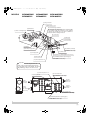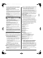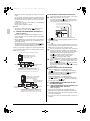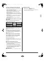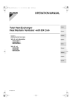
1
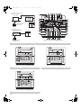
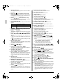
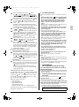
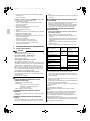
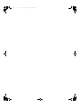
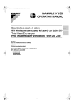
00_CV_3P130767-4K_01.fm 1 ページ 2013年3月8日 金曜日 午後3時52分 OPERATION MANUAL Total Heat Exchanger Heat Reclaim Ventilator -with DX CoilMODELS (Ceiling mounted duct type) With DX coil & Humidifier VKM50GBMV1 VKM80GBMV1 VKM100GBMV1 With DX coil VKM50GBV1 VKM80GBV1 VKM100GBV1 English Deutsch Français Español Italiano Ελληνικά Nederlands Portugues Р сс ий 3P130767-4K 00_CV_3P130767-4K_02.fm 0 ページ 2013年3月21日 木曜日 午前11時52分 Heat Reclaim Ventilator Heat Reclaim Ventilator • Thank you for purchasing this Daikin total heat exchanger. Carefully read this operation manual before using the Heat Reclaim Ventilator. It will tell you how to use the unit properly and help you if any trouble occurs. This manual explains about the indoor unit only. Use it along with the operation manual for the outdoor unit. After reading the manual, file it away for future reference. • This unit is an option type for the VRV system air conditioner. It should normally be used in combination with the VRV system indoor air conditioner. It is also possible to use this unit as a independent system. • This unit cannot control room temperature. If this is needed, do not install the Heat Reclaim Ventilator unit alone, but rather install another indoor unit. • Use the remote controller of the VRV system indoor air conditioner to control the unit. Wärmerückgewinnungslüftung • Danke, dass Sie sich für den Wärmetauscher von Daikin entschieden haben. Lesen Sie diese Bedienungsanleitung sorgfältig durch, bevor Sie die Wärmerückgewinnungslüftung verwenden. Hier erfahren Sie, wie Sie das Gerät korrekt betreiben. In diesem Handbuch wird nur die Installation der Inneneinheit beschrieben. Verwenden Sie es zusammen mit dem Bedienungshandbuch der Außeneinheit. Bewahren Sie die Anweisung gut auf, wenn Sie sie durchgelesen haben, damit Sie auch später noch darin nachschlagen können. • Das Gerät ist eine Option für das VRV-Klimagerät. Sie sollte normalerweise in Kombination mit der Innenklimaanlage des VRV-Systems verwendet werden. Zusätzlich kann das Gerät als eigenständiges System verwendet werden. • Dieses Gerät kann nicht zu Regulierung der Raumtemperatur verwendet werden. Wenn dies notwendig ist, installieren Sie das Wärmerückgewinnungslüftungsgerät nicht allein, installieren Sie sondern eher ein anderes Innengerät. • Das Gerät wird über die Fernbedienung der VRV-Inneneinheit gesteuert. Ventilateur Récupérateur de Chaleur • Nous vous remercions pour avoir choisi cet échangeur de chaleur à enthalpie totale Daikin. Lisez attentivement ce manuel d’utilisation avant d’utiliser la ventilation avec récupération de chaleur. Il vous enseignera à utiliser correctement l’unité et vous aidera en cas de panne. Ce manuel traite uniquement de l’unité intérieure. Utilisez-le avec le manuel d’utilisation de l’unité extérieure. Après avoir lu le manuel, rangezle en vue d’une utilisation ultérieure. • Cette unité est en option pour le climatiseur du système VRV. Il doit être normalement utilisé en combinaison avec le système VRV de climatiseur intérieur. Cette unité peut également être utilisée en tant que système indépendant. • Cette unité ne peut commander la température ambiante. Si cela est nécessaire, n’installez pas l’unité de ventilation avec récupération de chaleur HRV seule, installez aussi une autre unité intérieure. • Utilisez la télécommande du climatiseur intérieur du système VRV pour commander l’unité. Ventilación con recuperación de calor • Muchas gracias por haber adquirido este intercambiador de calor total Daikin. Lea detenidamente este manual de funcionamiento antes de utilizar la ventilación con recuperación de calor. El manual explica cómo usar la unidad correctamente y lo ayuda en caso de que surjan problemas. Este manual trata sobre la unidad interior solamente. Utilícelo conjuntamente con el manual de uso de la unidad exterior. Después de leerlo, guárdelo para referencia futura. • Esta unidad es un equipamiento opcional para el sistema de climatización VRV. Debe utilizarse, por norma general, en combinación con el sistema de climatización interior VRV. También es posible utilizar esta unidad a modo de sistema independiente. • Esta unidad no puede controlar la temperatura ambiente. Si fuese necesario, no instale solo la unidad de ventilación con recuperación de calor, en su lugar, instale otra unidad interior. • Utilice el mando a distancia del sistema de climatización interior VRV para controlar esta unidad. Ventilatore a recupero di calore • Grazie di aver acquistato questo scambiatore di calore totale Daikin. Leggere attentamente questo manuale d’uso prima di utilizzare il ventilatore a recupero di calore. Esso insegna il modo corretto di utilizzare l’unità e fornisce consigli, nel caso si verifichino dei problemi. Il manuale si riferisce solo all’unità interna. Usarlo insieme al manuale di istruzioni dell’unità esterna. Dopo aver letto il manuale, conservarlo per riferimenti futuri. • Questa unità è un tipo opzionale di condizionatore d’aria a sistema VRV. Normalmente dovrebbe essere usato in combinazione con il condizionatore d’aria interno del sistema VRV. È anche possibile utilizzare questa unità come sistema indipendente. • L’unità non può controllare la temperatura del locale. Se ciò è necessario, non installare l’unità ventilatore a recupero di calore da sola, invece installare un’altra unità interna. • Per controllare l’unità, utilizzare il telecomando del condizionatore d’aria interno a sistema VRV. Εξαεριστήρας με Ανάκτηση Θερμότητας • Ευχαριστούμε για την αγορά σας αυτού του εναλλάκτη συνολικής θερμότητας Daikin. Διαβάστε προσεκτικά το παρόν εγχειρίδιο λειτουργίας πριν από τη χρήση του Εξαεριστήρα με Ανάκτηση Θερμότητας. Θα σας πουν πως θα χρησιμοποιήσετε σωστά τη μονάδα και θα σας βοηθήσουν αν εμφανιστούν προβλήματα. Το παρόν εγχειρίδιο δίνει εξηγήσεις μόνο για την εσωτερική μονάδα. Χρησιμοποιήστε το μαζί με το εγχειρίδιο λειτουργίας της εξωτερικής μονάδας. Aφού διαβάσετε τις οδηγίες, βάλτε τις στο αρχείο σας για μελλοντική αναφορά. • Αυτή η μονάδα είναι εναλλακτικός τύπος για το σύστημα κλιματισμού VRV. Κανονικά, θα πρέπει να χρησιμοποιείται σε συνδυασμό με το σύστημα VRV εσωτερικού κλιματιστικού. Υπάρχει επίσης η δυνατότητα να χρησιμοποιήσετε αυτή τη μονάδα ως ανεξάρτητο σύστημα. • Η μονάδα αυτή δεν ελέγχει τη θερμοκρασία του χώρου. Εάν αυτό είναι απαραίτητο, μην εγκαταστήσετε τη μονάδα του Εξαεριστήρα με Ανάκτηση Θερμότητας μόνο, αλλά καλύτερα εγκαταστήστε άλλη εσωτερική μονάδα. • Χρησιμοποιήστε το τηλεχειριστήριο του συστήματος κλιματισμού εσωτερικής μονάδας VRV για έλεγχο της μονάδας. Hergebruik van Warmte • Hartelijk dank voor uw keuze voor een warmtewisselaar van Daikin. Lees deze bedieningshandleiding aandachtig door voordat u de HRV gebruikt. In de gebruiksaanwijzing kunt u lezen hoe u het apparaat op de juiste manier gebruikt en wat u kunt doen bij storingen. Deze handleiding bevat alleen informatie over de binnenunit. Gebruik deze handleiding samen met die van de buitenunit. Bewaar deze gebruiksaanwijzing nadat u deze heeft gelezen. • Dit apparaat is een optioneel model voor de airconditioners in een VRV-systeem. Het dient normaal gesproken gebruikt te worden in combinatie met de VRVsysteem binnenairconditioner. Het is ook mogelijk om dit apparaat als onafhankelijk systeem te gebruiken. • Dit apparaat kan niet worden gebruikt om de temperatuur in een ruimte te regelen. Als dit nodig is, installeer dan niet alleen de Hergebruik van Warmte-unit, maar installeer liever een andere binnenunit. • Gebruik de afstandsbediening de binnenunit van het VRV-systeem om het apparaat te bedienen. Ventilação de Recuperação Térmica • Agradecemos a aquisição deste permutado térmico total da Daikin. Leia atentamente este manual de funcionamento antes de usar a Ventilação de Recuperação Térmica. Nele obterá informações sobre o modo de utilizar correctamente o aparelho e ajuda na eventualidade de ocorrência de problemas. Este manual fornece explicações exclusivamente sobre a unidade interior. Utilize-o em conjunto com o manual de funcionamento da unidade exterior. Depois de ler o manual, guarde-o para consultas futuras. • Esta unidade é uma opção para o aparelho de ar condicionado do sistema VRV. Deve ser utilizado normalmente em combinação com o ar condicionado interior com sistema VRV. É também possível utilizar esta unidade como sistema independente. • Esta unidade não controla a temperatura do compartimento. Se isso for necessário, não instale a unidade de Ventilação de Recuperação Térmica sozinha, mas instale também outra unidade interior. • Utilize o controlador remoto do aparelho de ar condicionado interior do sistema VRV para controlar a unidade. Вентилятор с рекуперацией тепла • Благодарим вас за покупку данного энтальпийного теплообменника Daikin. Внимательно прочтите данное руководство по эксплуатации, прежде чем приступить к работе с вентилятором с рекуперацией тепла. В нем излагаются правила надлежащего пользования устройством и приводятся рекомендации пользователю по поиску и устранению неисправностей. В данном руководстве рассматривается только комнатный блок. Используйте его вместе с руководством для наружного блока. После изучения руководства сохраните его для обращений в будущем. • Данный блок является дополнительным для кондиционера системы VRV. Он должен использоваться вместе с комнатным кондиционером воздуха системы VRV. Данный блок также можно использовать в качестве независимой системы. • Данный блок не может контролировать температуру в помещении. Если это необходимо, Вам следует установить не вентилятор с рекуперацией тепла, а другой внутренний блок. • Используйте пульт дистанционного управления комнатным кондиционером системы VRV для управления данным блоком. 00_CV_3P130767-4K_02.fm MODELS 1 ページ 2013年3月21日 木曜日 午前11時52分 VKM50GBMV1 VKM50GBV1 VKM80GBMV1 VKM80GBV1 VKM100GBMV1 VKM100GBV1 (1) Hanger bracket (7) Maintenance cover (8) Heat exchanger elements (3) Exhaust fan It exchanges the heat (temperature and humidity) from indoors with the air taken in from outdoors, changes the outside air to the same condition as indoors and then brings it indoors. (2) Duct connecting flange (6) Control box (12) Gas pipe (13) Liquid pipe (5) Damper (16) Strainer (included) (4) Air filter (Long life filter) <VKM-GBMV1 series only> (10) Air supply fan (14) Drain outlet (19) Remote controller (Optional accessory) (9) Name plate (15) Humidifier (Natural evaporating type) <VKM-GBMV1 series only> (11) Direct expansion coil Important Sometimes when first using the unit, the smell of the heat exchanging element may be noticeable, but it is not harmful. The smell will gradually go away as the unit is used. (11) Direct expansion coil (17) Feed water tank (20) Damper motor <VKM-GBMV1 series only> (23) RA Return air from room (21) EA Exhaust air to outdoors (24) SA Supply air to room (22) OA Fresh air from outdoors (outdoor air) (18) Solenoid valve <VKM-GBMV1 series only> (15) Humidifier (Natural evaporating type) <VKM-GBMV1 series only> 1 [1] 00_CV_3P130767-4K_02.fm 2 ページ 2013年3月21日 木曜日 午前11時52分 • Combined operation system with VRV systems Heat Reclaim Ventilator -With DX Coil- Indoor unit Remote controller for indoor unit Outdoor unit • Independent system Heat Reclaim Ventilator -With DX Coil- Outdoor unit Remote controller for VKM BRC1D527 Remote controller for indoor unit 3 2 4 UNIT No. UNIT No. GROUP GROUP 1 1,2,3 2 3 Remote controller for VKM BRC1D527 4 5 UNIT No. GROUP 1,2,4 7,8 3,5 6 Remote controller for VKM BRC1D527 6 [2] Remote controller for VKM BRC1D527 01_EN_3P130767-4K.fm 1 ページ 2013年3月21日 木曜日 午前11時50分 With DX coil & Humidifier VKM50GBMV1 VKM80GBMV1 VKM100GBMV1 With DX coil VKM50GBV1 VKM80GBV1 VKM100GBV1 Total Heat Exchanger Heat Reclaim Ventilator -with DX Coil- CONTENTS 1 2 3 4 5 6 ILLUSTRATIONS (figure) ...........................................[1][2] SAFETY PRECAUTIONS ................................................1 WHAT TO DO BEFORE OPERATION .............................3 OPERATION PROCEDURE ............................................6 MAINTENANCE (for a qualified service person only) ......9 TROUBLE SHOOTING ..................................................10 AFTER-SALES SERVICE AND WARRANTY................12 The original instructions are written in English. All other languages are translations of the original instructions. Important information regarding the refrigerant used • • • • This product contains fluorinated greenhouse gases covered by the Kyoto Protocol. Refrigerant type: R410A (1) GWP value: 1975 (1) GWP = global warming potential • Periodical inspections for refrigerant leaks may be required depending on European or local legislation. Please contact your local dealer for more information. • 1 • SAFETY PRECAUTIONS To gain full advantage of the Heat Reclaim Ventilator unit’s functions and to avoid malfunction due to mishandling, please read this operation manual carefully before use. This product comes under the term “appliances not accessible to the general public”. • This manual classifies the precautions into WARNINGS and CAUTIONS. Be sure to follow all the precautions below: They are all important for ensuring safety. WARNING ...............Indicates a potentially hazardous situ- • • ation which, if not avoided, could result in death or serious injury. CAUTION ................Indicates a potentially hazardous situa- tion which, if not avoided, may result in minor or moderate injury. It may also be used to alert against unsafe practices. • After reading, keep this manual in a convenient place so that you can refer to it whenever necessary. If the equipment is transferred to a new user, be sure also to hand over the manual. • • • • WARNING (During Operation) Be aware that prolonged, direct exposure to cool or warm air from the Heat Reclaim Ventilator unit, or to air that is too cool or too warm can be harmful to your physical condition and health. Do not place objects, including rods, your fingers, etc., in the air inlet or outlet. Injury may result due to contact with the Heat Reclaim Ventilator unit’s highspeed fan blades. Do not use the Heat Reclaim Ventilator unit in the atmosphere contaminated with oil vapor, such as cooking oil or machine oil vapor. Oil vapor may cause crack damage to the Heat Reclaim Ventilator unit, electric shocks, or a fire. Do not use the Heat Reclaim Ventilator unit in places with excessive oily smoke, such as cooking rooms, or in places with flammable gas, corrosive gas, or metal dust. 3P130767-4K English • Operation manual Using the Heat Reclaim Ventilator unit in such places may cause a fire or Heat Reclaim Ventilator unit failures. Do not use flammable materials (e.g., hairspray or insecticide) near the Heat Reclaim Ventilator unit. Do not clean the Heat Reclaim Ventilator unit with organic solvents such as paint thinner. The use of organic solvents may cause crack damage to the Heat Reclaim Ventilator unit, electric shocks, or a fire. To avoid electric shocks, do not operate with wet hands. Open the windows and ventilate the room if flammable gas is leaked. Insufficient ventilation when the unit is turned on or off may cause an explosion from sparks at the electrical connection. Do not wash the Heat Reclaim Ventilator unit with water, as this may result in electric shocks or a fire. (Not including air filters, etc.) Be sure to stop the unit and turn off the power when cleaning or inspecting it. As the fan is rotating at high speed, it will cause injury. Never inspect or service the unit by yourself. Ask a qualified service person to perform this work. (The qualified service person) Beware of a fire in case of refrigerant leakage. If the Heat Reclaim Ventilator unit is not operating correctly, i.e. not generating cool or warm air, refrigerant leakage could be the cause. Consult your local dealer for assistance. The refrigerant used for the Heat Reclaim Ventilator unit is safe and normally does not leak. However, if the refrigerant leaks and gets in contact with a naked burner, heater or cooker, it may generate hazardous compounds. Turn off the Heat Reclaim Ventilator unit and call your local dealer. Turn on the Heat Reclaim Ventilator unit after the qualified service person makes sure to confirm that the leakage is repaired. Consult your local dealer if the Heat Reclaim Ventilator unit submerges owing to a natural disaster, such as a flood or typhoon. Do not operate the Heat Reclaim Ventilator unit in that case, or otherwise a malfunction, electric shocks, or a fire may result. Start or stop the Heat Reclaim Ventilator unit with the remote controller. Never use the power circuit breaker for this purpose. Otherwise, it may cause a fire or water leakage. Furthermore, if an automatic restart control is provided against power failure and the power is recovered, the fan will rotate suddenly and may cause injury. Consult your local dealer regarding cleaning the inside of the Heat Reclaim Ventilator unit. Improper cleaning may cause breakage of plastic parts, water leakage and other damage as well as electric shocks. CAUTION (During Operation) • Do not use the Heat Reclaim Ventilator unit for purposes other than those for which it is intended. Do not use the Heat Reclaim Ventilator unit for cooling precision instruments, food, plants, animals or works of art as this may adversely affect the performance, quality and/or longevity of the object concerned. • Do not place appliances that produce naked flames in places exposed to the airflow from the Heat Reclaim Ventilator unit as this may impair combustion of the burner. • Do not place heaters directly below the Heat Reclaim Ventilator unit, as resulting heat can cause deformation. • Be sure that children, plants or animals are not exposed directly to airflow from the Heat Reclaim Ventilator unit, as adverse effects may ensue. • Do not place flammable sprays or operate spray containers near the Heat Reclaim Ventilator unit or indoor intake and outlet grills as this may result in a fire. 1 01_EN_3P130767-4K.fm 2 ページ 2013年3月21日 木曜日 午前11時50分 • Turn off the power when the Heat Reclaim Ventilator unit is not used for long periods of time. Otherwise, the Heat Reclaim Ventilator unit may get hot or catch on a fire due to dust accumulation. • Do not block air inlets nor outlets. If the fan does not blow air throughout the entire room, it may cause oxygen deficiency leading to bad health condition or long-term health problems. • Do not operate the Heat Reclaim Ventilator unit without air filter. This may cause a malfunction as the heat exchange element may be clogged with dirt or dust. • Use gloves when cleaning. Cleaning without gloves may cause injury. • Never disassemble the remote controller. Touching the interior parts may result in electric shocks or a fire. Consult your local dealer for internal inspections and adjustments. • Do not place objects in direct proximity of the outdoor unit and do not let leaves and other debris accumulate around the unit. Leaves are a hotbed for small animals which can enter the unit. Once in the unit, such animals can cause malfunctions, smoke or a fire when making contact with electrical parts. • Watch your steps at the time of air filter cleaning or inspection. High-place work is required, to which utmost attention must be paid. If the scaffold is unstable, you may fall or topple down, thus causing injury. • Do not place water containers (flower vases, etc.) on the Heat Reclaim Ventilator unit, as this may result in electric shocks or a fire. • The appliance is not intended for use by unattended young children or persons who are incompetent to operate air conditioners. It may result in injury or electric shocks. • Children should be watched so that they do not play with the indoor unit or its remote controller. Accidental operation by a child may result in injury or electric shocks. WARNING (For installation) • Consult your local dealer about installation work. Doing the work yourself may result in water leakage, electric shocks or a fire. • Installation should be done following the installation manual. Incorrect installation may cause leaking, electric shock, or a fire. Injuries may result if the unit falls. • Do not install the unit in locations where the temperature in the areas around the unit or indoor intake and outlet grills may fall below freezing. <VKM-GBMV1 series only> The water of the water pipes, humidifier element, solenoid valves, and other components may freeze, causing breakage and leaks. • Do not allow exhaust air to enter the outside air intake vent. This may cause the interior of the room to become contaminated and harming the health. • Locate the outside air intake vent so that it does not take in exhaust air which contains combustion air, etc. Incorrect installation may cause a loss of oxygen in the room, leading to serious accidents. • All wiring must be performed by an authorized electrician. To do wiring, ask your local dealer. Never do it yourself. • Make sure that a separate power supply circuit is provided for this unit and that all electrical work is carried out by qualified personnel according to local lows and regulations. Insufficient power circuit capacity or incorrect work may cause electric shock or a fire. • Be sure to earth the Heat Reclaim Ventilator unit. Do not earth the Heat Reclaim Ventilator unit to a utility piping, lightning conductor or telephone earth lead. Imperfect earthing may result in electric shocks or a fire. A high surge current from lightning or other sources may cause damage to the Heat Reclaim Ventilator unit. 2 • Be sure to install an earth leakage breaker. Failure to install an earth leakage breaker may result in electric shocks, or a fire. • Install the unit on a foundation strong enough to withstand the weight of the unit. A foundation of in sufficient strength may result in the unit falling and causing injuries. • Connect the remote controller to the correct model. This may cause electric shock or a fire. • Do not connect additional electric wirings. This may cause a fire. • Consult your local dealer regarding what to do in case of refrigerant leakage. When the Heat Reclaim Ventilator unit is installed in a small room, it is necessary to take proper measures so that the amount of any leaked refrigerant does not exceed the concentration limit in the event of a leakage. Otherwise, this may lead to an accident due to oxygen depletion. • Do not install the Heat Reclaim Ventilator unit at any place where there is a danger of flammable gas leakage. In the event of a gas leakage, build-up of gas near the Heat Reclaim Ventilator unit may result in a fire. CAUTION (For installation) • Do not use the Heat Reclaim Ventilator unit or an air suction/discharge grille in the following places. 1. Place subjected to high temperature or direct flame. Avoid a place where the temperature near the Heat Reclaim Ventilator unit and the air suction/discharge air grille exceeds 40°C. If the unit is used at high temperature, deformed air filter and heat exchange element or burned motor result. 2. Place such as kitchens or other places where oil fumes are present. This may cause a fire. 3. Place such as machinery plant and chemical plant where gas, which contains noxious gas or corrosive components of materials such as acid, alkali, organic solvent and paint, is generated. Place where combustible gas leakage is likely. This may cause gas poisoning or a fire. 4. Place such as bathroom subjected to moisture. Electric leak or electric shock and other failure can be caused. 5. Locations below freezing point. <VKM-GBMV1 series only> Using the unit at temperatures below 0°C may cause the drain pan the supply and discharge piping, the humidifying element, the solenoid valves, and other parts to freeze, which can cause accidents. 6. Near machinery emitting electromagnetic waves. Electromagnetic waves may disturb the operation of the control system and result in a malfunction of the equipment. 7. Place subjected to much carbon black. Carbon black attaches to air filter and heat exchange element, marking them unable to use. • Is a snow protection measure taken? For detail, consult your local dealer. • Make sure the temperature and the humidity of the installation location is within the usage range, not exceed the limit. Do not install in cold storage or other locations with low temperatures or near heated pools. This may cause electrical shock and a fire. • Install the two outdoor ducts with down slope to prevent rainwater from entering the unit. If this is not done completely, water may enter the building, damaging furniture, and cause electric shock and a fire. • Insulate the two outdoor ducts to prevent dew condensation (and the indoor duct as well if needed). If this is not done completely, water may enter the building, damaging furniture, etc. 3P130767-4K English 01_EN_3P130767-4K.fm 3 ページ 2013年3月21日 木曜日 午前11時50分 • Use electric insulation between the duct and the wall when using metal ducts to pass metal or wire laths or metal plating into wooden buildings. This may cause electric shock and a fire. • Carry out drain piping properly to ensure complete drainage. If drain piping is not carried out properly, drain will not flow out. Then, dirt and debris may be accumulated in the drain piping and may cause water leakage. If it occurs, stop the Heat Reclaim Ventilator unit and call your local dealer for assistance. • Do not locate the remote controller wherever there is a risk of wetting. If water gets into the remote controller there is a risk of electrical leakage and damage to electronic components. It may result electric shocks or a fire. • • • • • • (For moving and reinstalling/ WARNING repairing) Do not modify the Heat Reclaim Ventilator unit. This may cause electric shock or a fire. Consult your local dealer regarding relocation and reinstallation of the Heat Reclaim Ventilator unit. Improper installation work may result in leakage, electric shocks or a fire. Do not disassemble or repair the unit yourself. This may cause electric shock or a fire. Contact your local dealer to have such work done. When removing the Heat Reclaim Ventilator unit, be sure not to tip it. The water inside the unit may drip or leak out, and get on furniture, etc. Do not relocate or reinstall the remote controller by yourself. Improper installation may result in electric shocks or a fire. Consult your local dealer. When the Heat Reclaim Ventilator unit is malfunctioning (giving off a burning odor, etc.), turn off the power to the Heat Reclaim Ventilator unit and contact your local dealer. Continued operation under such circumstances may result in a failure, electric shocks or a fire. <CHECK LIST EXCEPT SAFETY CAUTION> The items described below should be checked and ask your local dealer when you feel uncertain or you can’t check by yourself. CHECK LIST ABOUT SELECTING INSTALLATION SITE • Is the outdoor unit installed in a well-ventilated location with no obstructions in its vicinity? • Do not use in the locations described below. a. Locations with mineral oil such as cutting oil in the atmosphere. b. Locations with salt in the air, such as coastal areas. c. Locations with sulfide gas in the air, such as hot springs. d. Locations where voltage fluctuates, such as factory. e. In automobiles or marine vessels. f. Locations containing steam in the atmosphere or splattered oil, such as kitchen. g. Locations with mechanical equipment generating electromagnetic wave. h. Locations enveloped in acidic or alkaline steam. • Has any action for snow protection been taken? Contact your local dealer for details. CHECK LIST CORRESPONDING TO OPERATING NOISE • Is the unit installed at the following locations? a. Location strong enough to support the weight of the unit, and which will not amplify noise or vibration. b. Location where the warm air and the noise from the outlet vent of the outdoor unit will not bother neighbors. • Are any obstructions near the outlet vent of the outdoor unit? They may reduce the function and increase the operating noise. • If any abnormal noise is heard during the operation, contact your local dealer. CHECK LIST ABOUT DRAIN PIPING AND WATER SUPPLY WORK • Make sure the drain works properly. During cooling operation, no drainage from the outdoor drain piping may clog the drain piping with dirt or dust, causing water leakage from the indoor unit. Stop the unit operation, and contact your local dealer. 2 WHAT TO DO BEFORE OPERATION This operation manual is for the following systems with standard control. Before initiating operation, contact your local dealer for the operation that corresponds to your system type and mark. If your installation has a customized control system, ask your local dealer for the operation that corresponds to your system. 2.1 NAMES OF PARTS (Refer to figure 1) (1) (2) (3) (4) (5) (6) (7) (8) (9) (10) (11) (12) (13) (14) (15) (16) (17) (18) (19) (20) (21) (22) (23) (24) Hanger bracket Duct connecting flange Exhaust fan Air filter (Long life filter) Damper Control box Maintenance cover Heat exchanger elements Name plate Air supply fan Direct expansion coil Gas pipe Liquid pipe Drain outlet Humidifier (Natural evaporating type) <VKM-GBMV1 series only> Strainer (included) <VKM-GBMV1 series only> Feed water tank <VKM-GBMV1 series only> Solenoid valve <VKM-GBMV1 series only> Remote controller (Optional accessory) Damper motor EA Exhaust air to outdoors OA Fresh air from outdoors (outdoor air) RA Return air from room SA Supply air to room 2.2 REMOTE CONTROLLER AND CHANGEOVER SWITCH: NAME AND FUNCTION OF EACH SWITCH AND DISPLAY (Refer to figure 3) • All wiring must be performed by an authorized electrician. Do not conduct the work yourself. Contact your local dealer. • Only the items marked with an asterisk ( mark) are explanation relating to the functions and display of the unit. Unmarked items are functions of the combined air conditioners. When using buttons for functions which are not available (buttons which are not described in the text) will cause “NOT AVAILABLE” to be displayed. Contact your local dealer for more detailed descriptions of those functions (buttons). • Electrical wiring must be done according to the local standards. • Is the circuit specific to air conditioner? 1 ON/OFF button Press the button and the system will start. Press the button again and the system will stop. CHECK LIST ABOUT ELECTRIC WIRING WORK 3P130767-4K English 3 01_EN_3P130767-4K.fm 4 ページ 2013年3月21日 木曜日 午前11時50分 2 Operation lamp (red) The lamp lights up during operation or blinks if a malfunction occurs. 3 Display “ ” (changeover under control) May be displayed when combined with a VRV-system air conditioner. It is impossible to changeover heat/cool with the remote controller when this icon is displayed. 4 Display “ ” (under centralized control) When this display shows, the system is under centralized control. (This is not a standard specification.) 5 LEAVE HOME ICON “ ” The leave home icon shows the status of the leave home function. ON Leave home is enabled. FLASHING Leave home is active. OFF Leave home is disabled. ” (defrost/hot start) 6 Display “ It may be displayed when freezing of outdoor unit’s coil increases in heating mode. 7 Display “ ” (air purifier) This display shows that the air cleaning unit is in operation. 8 Display “ ”“ ”“ ”“ ”“ ” (operation mode: “FAN, DRY, AUTOMATIC, COOLING, HEATING”) This displays the operating status of the combined air conditioner. • There is no “heating” for the VRVIII system (Cooling only type). • “ ” is only available for systems operating in cooling and heating at the same time. 9 Remote controller thermo This detects the temperature around the remote controller. This is not the same as the temperature of return air from room (RA) by heat exchanger unit. 10 Display “ ”“ ”“ ” This displays the ventilation mode. 11 MAXIMUM SET TEMPERATURE “ ” The maximum set temperature indicates the maximum set temperature when in limit operation. 12 SCHEDULE TIMER ICON “ ” This icon indicates that the schedule timer is enabled. ” (inspection/test operation) 13 Display “ When the inspection/test operation button is pressed, the display shows the mode in which the system actually is. • Do not use under usual use (service person/installer only). 14 OFF ICON “ ” This icon indicates that the OFF action is selected when programming the schedule timer. 15 MINIMUM SET TEMPERATURE “ ” The minimum set temperature indicates the minimum set temperature when in limit operation. 16 ACTION ICONS “ ” These icons indicate the actions for each day of the schedule timer. 17 Display “ C ” (set temperature) This displays the set temperature of the combined air conditioner. It is not displayed when the unit is used as an independent system. 4 18 Ventilation mode selector button This is pressed to switch the ventilation mode. 19 Fan speed control button This is pressed to control the fan speed. (Refer to item 30) 20 Inspection/test operation button Not used, for service purpose only. 21 PROGRAMMING BUTTON “ ” This button is a multi-purpose button. Depending on the previous manipulations of the user, the programming button can have various functions. 22 SCHEDULE TIMER BUTTON “ ” This button enables or disables the schedule timer. 23 Programming time button Use this button for programming start and/or stop time. 24 Display “ ” (air flow flap) This displays the direction and mode of the air flow flap of the combined air conditioner. 25 Temperature setting button Use this button for setting the desired temperature of air conditioner combined with this unit. This button can’t use for this unit. This unit can’t change temperature setting. 26 SETPOINT/LIMIT BUTTON “ ” This button toggles between setpoint, limit operation or (programming mode only). 27 OPERATION CHANGE/ BUTTON “ ” This button is a multi-purpose button. Depending on the previous manipulations of the user, it can have following functions: 1 Select The operation mode of the installation (FAN, DRY, AUTOMATIC, COOLING, HEATING). 2 Toggle between minimum temperature and maximum temperature when in limit operation. 28 DAY OF THE WEEK INDICATOR “ ” The day of the week indicator shows the current week day (or the set day when reading or programming the schedule timer). 29 CLOCK DISPLAY “ ” The clock display indicates the current time (or the action time when reading or programming the schedule timer). ” (fan speed) 30 Display “ This display shows the fan speed you have selected. This is only displayed when the fan speed selection button is pressed. It normally displays the set fan strength of the combined air conditioner. 31 ELEMENT CLEANING TIME ICON “ ” This icon indicates the element must be cleaned. 32 Display “ ” (time to clean air filter) Refer to “4.1 WHEN TO PERFORM MAINTENANCE OF THE AIR FILTER”. 33 Display “ ” (ventilation) This display shows that the total heat exchange is in operation. 34 Display “NOT AVAILABLE” • “NOT AVAILABLE” may be displayed for a few seconds if the function for the button pressed is not available for the unit or the air conditioner. • “NOT AVAILABLE” is only displayed when none of the indoor units is equipped with the function in question when running several units simultaneously. It is not displayed if the function is available on even one of the units. 3P130767-4K English 01_EN_3P130767-4K.fm 5 ページ 2013年3月21日 木曜日 午前11時50分 35 Air conditioner fan speed control button Press this button to select the fan speed of air conditioner combined with this unit. 2.4 ABOUT DIRECT DUCT CONNECTION SYSTEM Installation Examples Direct duct connection system 36 Air flow direction adjust button Press this button to select the air flow direction of air conditioner combined with this unit. 37 Filter sign reset button Refer to “4.1 WHEN TO PERFORM MAINTENANCE OF THE AIR FILTER”. (Refer to page 9) NOTE • In contradistinction to actual operating situations, the display on figure 3 shows all possible indications. • If the filter sign lamp lights up, clean the air filter as explained in the chapter “4 MAINTENANCE”. After cleaning and reinstalling the air filter: press the filter sign reset button on the remote controller. The filter sign lamp on the display will go out. • Only the items marked with an asterisk ( mark) are explanation relating to the functions and display of the unit. Unmarked items are functions of the combined air conditioners. 2.3 EXPLANATION FOR SYSTEMS This unit can be made a part of two different systems: as part of the combined operation system used together with VRVII SYSTEM Air Conditioners and as the independent system using only the Heat Reclaim Ventilator. An operating remote controller is required when using the unit as an independent system. Ask your local dealer for what kind of your system is set up before operation. For the operation of the remote controller for indoor unit and centralized controller, refer to the operation manual provided with each unit. See the included operating manuals for details on how to operate each remote control. (HC0007) NOTE) • The system must be operated interlocking with the air conditioner. • Do not connect to the outlet side of the indoor unit. Independent duct system (HC0008) The Heat Reclaim Ventilator unit cannot be operated independently when the air conditioner is connected to the Heat Reclaim Ventilator unit via a duct. When using the Heat Reclaim Ventilator unit, set the air conditioner to “fan” mode on weak fan strength. Operation mode display “Ventilation” is displayed. Operation mode selector button OPERATION FOR EACH SYSTEM Sample system (Refer to figure 2) Combined operation system with VRVIII systems [Operation] The air conditioner remote controller starts and stops the air conditioner and the Heat Reclaim Ventilator unit. You can also select the ventilation amount and the ventilation mode. Refer to “3 OPERATION PROCEDURE”. During intermediate periods when only the Heat Reclaim Ventilator unit is used without the air conditioner, select “ventilation” with the operation selection button. (Refer to 2.4) Remote controller for indoor unit • Each time you press the operation selection button, the operation mode display will change as shown in the figure below. Sample system (Refer to figure 2) Independent system [Operation] The Heat Reclaim Ventilator unit can be started and stopped using the remote controller. You can also select the ventilation amount and the ventilation mode. Refer to “3 OPERATION PROCEDURE”. NOTE • This unit cannot control room temperature. If this is needed, do not install the Heat Reclaim Ventilator unit alone, but rather install another indoor unit. 3P130767-4K English 5 2013年3月21日 木曜日 午前11時50分 When air conditioner and Heat Reclaim Ventilator unit are not connected via duct <Operation mode> VRV: Cooling mode Heat Reclaim Ventilator: Heat exchange mode 2.5 NIGHTTIME FREE COOLING OPERATION <AUTOMATIC HEAT PURGE FUNCTION AT NIGHT> The nighttime free cooling is an energy-conserving function which works at night when the air conditioners is OFF, reducing the cooling load in the morning when the air conditioner is turned on by ventilating rooms which contain office equipment which raises the room temperature. • Nighttime free cooling only works during cooling and when connected to or VRV systems. • Nighttime free cooling is set to “OFF” in the factory settings; so request your local dealer to turn it on if you intend to use it. Operation image VRV: Fan mode Heat Reclaim Ventilator: Heat exchange mode VRV: Stopping Heat Reclaim Ventilator: Heat exchange mode 40 (a) 30 20 (c) (b) OFF ON OFF Nighttime free cooling operation (e) Example 1: In case of the remote controller “BRC1D527” and as equivalent. Display changes as below. (d) 6 ページ Operating state temperature (°C) 01_EN_3P130767-4K.fm OFF 22:00 24:00 Next morning (time) (a) Outside temperature (b) Indoor temperature When air conditioner and Heat Reclaim Ventilator unit are connected via duct (c) Set temperature (d) Operating state of Air conditioner (e) Operating state of Total heat exchanger <Operation mode> VRV: Cooling mode Heat Reclaim Ventilator: Heat exchange mode VRV: Fan mode Heat Reclaim Ventilator: Heat exchange mode NOTE) Current Ventilation mode can be visible and selected on the remote controller. • When the display shows “ ” (time to clean air filter), ask a qualified service person to clean the filters (Refer to the chapter “4 MAINTENANCE”). EXPLANATION OF NIGHTTIME FREE COOLING OPERATION IMAGE The unit compares the indoor and outdoor temperatures after the air conditioning operation stops for the night. If the following conditions are satisfied, the operation starts, and when the indoor temperature reaches the air conditioning setting, the operation stops. <Conditions> [1] the indoor temperature is higher than the air conditioning setting and [2] the outdoor temperature is lower than the indoor temperature, If the above conditions are not satisfied, reevaluation is made every 60 minutes. 3 OPERATION PROCEDURE 3.1 COOLING, HEATING, AND FAN ONLY OPERATION (Refer to figure 4) [PREPARATIONS] • To protect the unit, turn on the main power switch 6 hours before operation. Do not turn off the power during the heating or cooling season. This is to ensure smooth start-up. Press the operation mode selector button several times and select the operation mode of your choice; 1 6 “ ” Cooling operation “ ” Heating operation “ ” Fan only operation 3P130767-4K English 01_EN_3P130767-4K.fm 7 ページ 2013年3月21日 木曜日 午前11時50分 EXPLANATION OF OPERATION MODE NOTE • “ ” can only be set for systems operating in cooling and heating at the same time. “ Heating mode ” is displayed on all remote controllers when using the VRV system cooling only type, but only “ “ ” is not displayed. “ ”“ ” and “ ” (only for simultaneous cooling/heating systems) cannot be selected on remote controllers on which it is displayed. See 3.2 if “ While operating in ventilation mode, the unit adjusts the outside air to the indoor temperature and then brings it into the room. ” is displayed. Press ventilation mode selector button if you wish to change the mode. The display rotates through the following selections every time the button is pressed. Automatic mode Heat exchange mode Bypass mode Automatic mode It automatically selects “ ” or “ ” and “ ” can be set. • Select the operating mode on a remote controller on which 2 Cooling mode .” Fan mode It only operates in ventilation mode. The unit processes outside air using the heat exchanger element, but not the DX expansion coil. NOTE • This unit cannot control room temperature. If this is needed, do not install the Heat Reclaim Ventilator unit alone, but rather install another indoor unit. EXPLANATION OF VENTILATION MODE NOTE Automatic mode NOTE • It is unnecessary to change ventilation mode because the mode is already set to “automatic mode”. 3 Press ventilation fan speed button if you wish to change the fan speed. The display rotates through the following selections every time the button is pressed. High Low L H After the selection, the ventilation fan speed display disappears. And the fan speed of the combined air conditioner regularly displays. NOTE • It is unnecessary to change four speed mode because the mode is already set to “Low” or “High” mode by the installer. 4 Press the ON/OFF button. The operation lamp lights up and the system starts operation. Stopping the system Press the ON/OFF button one more time. The operation lamp will go off. The unit will stop. • After stopping operation, the fan may continue operating for up to a minute. • The fan may stop, but this is not a malfunction. NOTE • Do not turn off the power immediately after operation stops. Wait at least 5 minutes. Not waiting may cause leaking or malfunction. • Do not change operations frequently in a short period of time. It can result not only in malfunction but also failure of switches or relays in the remote controller. • Never press the button of the remote controller with a hard, pointed object. The remote controller may be damaged. 3P130767-4K English : Combined with a VRVIII-system air conditioner The unit automatically switches between “ ” and “ ” based on information from the VRV systems air conditioner (heating, cooling, fan, and set temperature) and information from the Heat Reclaim Ventilator unit (indoor and outdoor temperatures). Independent system The unit automatically switches between “ ” and “ ” when it is combined with an air conditioner (Not produced by Daikin) and based on only the information from the Heat Reclaim Ventilator unit (indoor and outdoor temperatures) when the Heat Reclaim Ventilator unit is operating alone. Total heat exchange mode : Outdoor air passes through the heat exchange element and heat exchanged air is sent into the room. Bypass mode : In this mode outdoor air does not through the heat exchange element, but rather sent into the room as is. EXPLANATION OF HEATING OPERATION Defrost operation • In heating operation, freezing of the outdoor unit’s coil increases. Heating capability decreases and the system goes into defrost operation. • The remote controller will read “ ” until the hot air starts blowing. • It returns to the heating operation again after 6 to 8 minutes (10 at the longest). • During defrost operation, the fans of the unit continues operation (factory setting). The purpose of this is to maintain the amount of ventilation and humidifying. • The change of the layout in the room should be examined when the cold draft from air supplying opening is feared. 7 01_EN_3P130767-4K.fm 8 ページ 2013年3月21日 木曜日 午前11時50分 • Though the fan can be stopped by the setting of remote controller. Do not stop the fan in the place where no ventilation by stopping the fan may cause the influence of diffusion of air which it is dirty and moisture into another room, or the inflow from outside the room. (outflow such as viruses from the sickroom, or smell leakage from the rest room, etc.) Contact your local dealer for details. HOW TO DESIGNATE THE MAIN REMOTE CONTROLLER 1 Press the operation mode selector button of the current MAIN remote controller for 4 seconds. The display showing“ ” (changeover under control) of all SUB remote controllers connected to the same outdoor unit or BS unit flashes on. Hot start • The remote controller will read “ ” until the hot air starts blowing, e.g. at the start of heating operation. 3.2 SETTING THE MAIN REMOTE CONTROLLER (Refer to figure 5) • When the system is installed as shown bellow it is necessary to designate one of the remote controllers as the MAIN remote controller. • “ ” flashes when the power is first turned on. • Only the MAIN remote controller can select cooling, heating, or automatic operation (the last only on simultaneous cooling/heating systems). • The ventilation mode can be changed regardless of the setting (MAIN or SUB). • The displays of SUB remote controllers show “ ” (changeover under control) and they automatically follow the operation mode directed by the MAIN remote controller. NOTE However, it is possible to changeover to program dry with SUB remote controllers if the system is in cooling operation set by the MAIN remote controller. • This unit cannot control room temperature. If the unit is connected to the same system with other indoor units, set the MAIN remote controller on the other indoor units. 2 (Cooling/heating selection operation systems) When multiple indoor units or this unit are connected to a single outdoor unit. 3 Indoor unit Heat Reclaim Ventilator -with DX coil- One of these remote controllers can be designated as the MAIN remote controller. (Simultaneous cooling/heating systems) If multiple indoor units or many of this unit are connected to outdoor unit via BS unit. BS unit: This is the unit which selects cooling and BS unit heating. Indoor unit Heat Reclaim Ventilator -with DX coilOne of these remote controllers can be designated as the MAIN remote controller. Press the operation mode selector button of the controller that you wish to designate as the MAIN remote controller. Then designation is completed. This remote controller is designated as the MAIN remote controller and the display showing “ ” (changeover under control) vanishes. The displays of other remote controller show “ ” (changeover under control). Press the operation mode selector button on the MAIN remote controller (i.e. a remote controller which does not display “ ”) to scroll through the modes. The display will scroll through “ ” – “ ” (only for simultaneous cooling/heating systems) – “ ” – “ ”. The display on SUB remote controllers will also change automatically. DETAILS AND ACTIVITY OF OPERATION • Setting the MAIN remote controller (without the “ ” display) to cooling/heating mode will make SUB remote controllers (with the “ ” display) to follow to the mode of the MAIN remote controller. Selection of fan mode is possible, however. • Setting the MAIN remote controller (without the “ ” display) to fan mode will make SUB remote controllers (with the “ ” display) any setting other than fan mode impossible. 3.3 PROGRAMMING START AND STOP OF THE SYSTEM WITH TIMER 3.3.1 HOW TO PROGRAM AND SET THE TIMER WITH THE REMOTE CONTROLLER “BRC1D527” (Refer to figure 6) • The controller is equipped with a schedule timer that enables the user to operate the installation automatically; setting the clock and day of the week is required to be able to use the schedule timer. • To set up clock, refer to the operation manual of the remote controller. 8 3P130767-4K English 01_EN_3P130767-4K.fm 1 2 3 4 5 6 9 ページ 2013年3月21日 木曜日 午前11時50分 Browse to Monday by pressing the “ ” button. The “ ” icon appears, “ ” will blink and one of the “ ” icons, one of the “ ” icons might be displayed but all other fields remain blank, indicating that no actions are programmed for Monday. Enter the program mode by holding down the “ ” button for 5 seconds, the “ ” icon will now blink too. Press the “ ” button to activate the first programmed action. A blinking “ ” is displayed indicating that the first programmed action for Monday is being programmed; The set temperature and clock display are blinking. Enter the time when the action must start using the “ ”&“ ” buttons (min. step = 10 minutes). Press the “ ” button to display the next programmed action. If a second action is programmed for Monday, “ ” will still be blinking and “ ” will appear. Assuming that 5 actions were programmed for Monday, a total of 5 presses will be required to display all programmed actions. Enter the time when the action must stop using the “ ”&“ ” buttons (min. step = 10 minutes). Press the “ ” button. “ ” icon displays. This icon means the unit will stop at the set time. When all data for the schedule timer actions for Monday are entered, you must confirm the programmed actions. Make sure the last schedule timer action you want to keep is selected (schedule timer actions with a higher number will be deleted). Now you must choose between 2 options: 7 1. CONFIRM AND COPY TO NEXT DAY The schedule timer action programmed for the current 8 day are also valid for the next day: use the “confirm last action and copy actions to next day” function by pressing the “ ” and “ ” buttons simultaneously for 5 seconds. “DAY OF THE WEEK INDICATOR” will change blinking from “ ” to “ ”. 2. CONFIRM ONLY The schedule timer action programmed for the current 9 day are only valid for the selected day: use the “confirm last action and go to next day” function by pressing the “ ” button for 5 seconds. Program mode is quit and depending on the choice made, the programmed actions are saved for Monday (and possibly Tuesday). PROGRAMMING THE OTHER DAYS OF THE WEEK Programming the other days of the week is identical to programming the first day of the week. “ selected day, “ ” is blinking to indicate the ” and “ ” are steady if actions were copied from Monday to Tuesday, only “ ” is displayed if no actions were copied from Monday to Tuesday. NOTE) The schedule timer will not: • control fan speed, • control air flow direction, • control ventilation mode, • control ventilation amount, • change the operation mode for a scheduled setpoint. The parameters listed above can be set manually, without interfering with the schedule timer. 3P130767-4K English 3.4 OPTIMUM OPERATION Observe the following precautions to ensure the system operates. • When the display shows “ ”, ask a qualified service person to clean the filters (Refer to “4 MAINTENANCE”). • Do not operate the Heat Reclaim Ventilator unit in Bypass mode when the room air is under heating in winter or when the outside temperature is 30°C or higher. This may cause condensation to form on the main unit or on discharge grill, or around air supply opening. • Keep the indoor unit and the remote controller at least 1 m away from televisions, radios, stereos, and other similar equipments. This may cause distorted picture or noise. • Turn off the main power supply switch when it is not used for long periods of time. When the main power switch is turned on, some watts of electricity is being used even if the system is not operating. Turn off the main power supply switch for saving energy. When reoperating, turn on the main power supply switch 6 hours before operation for smooth running. • Use city water or clean water and take steps to prevent condensation from forming. (VKM-GBMV1 series only) • The life of humidifier become shorter when the supply water is hard water. (VKM-GBMV1 series only) Use a water softener. • Do not install the remote controller where the indoor temperature and humidity, respectively, are out of the range of 0-35°C and RH 40-80%. This may cause malfunction. • Do not install the remote controller where direct sunlight may fall on it. This may cause discoloration or deformation. NOTE • When the solenoid valve fails, the remote controller does not display any error code. Usage under that status will lead to insufficient humidification and increased tap water consumption. The solenoid valve should be checked at the beginning of the heating season. (VKM-GBMV1 series only) 4 MAINTENANCE (for a qualified service person only) ONLY A QUALIFIED SERVICE PERSON IS ALLOWED TO PERFORM MAINTENANCE DO NOT CHECK OPENING INSIDE THE UNIT BY YOURSELF. • Working at high places can cause accidents. Ask your local dealer for maintenance. 4.1 WHEN TO PERFORM MAINTENANCE OF THE AIR FILTER Clean the air filter when the display shows “ CLEAN AIR FILTER). ” (TIME TO It will display that it will operate for a set amount of time. AT LEAST ONCE EVERY YEARS (FOR GENERAL OFFICE USE) (CLEAN THE AIR FILTER MORE FREQUENTLY IF NECESSARY.) • Ask your local dealer to clean the air filter. • Increase the frequency of cleaning if the unit is installed in a room where the air is extremely contaminated. For remote controllers which display the filter sign, turn on the power after maintenance, and press the filter sign reset button. 9 01_EN_3P130767-4K.fm 10 ページ 2013年3月21日 木曜日 午前11時50分 Consult your local dealer if you want to change the time setting for when the filter sign goes on. CAUTION • Always use the air filter. If the air filter is not used, heat exchange elements will be clogged, possibly causing poor performance and subsequent failure. WHEN TO CLEAN THE HEAT EXCHANGE ELEMENT AT LEAST ONCE EVERY TWO YEARS (FOR GENERAL OFFICE USE) (CLEAN THE ELEMENT MORE FREQUENTLY IF NECESSARY.) 4.2 SEASONAL MAINTENANCE <VKM-GBMV1 SERIES ONLY> For dealers Strainer (80-mesh) Content of maintenance Items to be inspected Problems if maintenance is not carried out Check for clogging Clean if clogged. Insufficient humidifying. Check o-ring for cracks Replace if cracked. Leaking. Check for operation of float switch Clean if it does not work properly due to buildup. Insufficient humidifying. Overflowed feed water tank. Clean if very dirty. Weak fan strength. Reduced humidifying capacity. Replace if it doesn’t work. Insufficient humidifying. Overflowed feed water tank. (Increased tap water consumption) Feed water tank Check for dirt Solenoid valve Solution Check for shutting and opening. Check in a similar fashion when checking the float switch operation. 4.3 INSPECTION OF THE FAN MOTER NOTE • When the fan fails, the remote controller displays error code. Usage under that status will lead to insufficient ventilation. The air supply and exhaust fans should be checked once every one or two months. You can make a simple check such as below way. To check the wind flow, hold a bar of which the end has a string or other similar lightweight item over the supply grille and exhaust grille. 10 • The humidifier element needs to be replaced regularly. The humidifier element should in general be replaced once every three years when supply water is soft water, but outside factors (If the water quality is hard water, etc.) as well as operating conditions (24-hour-a-day air conditioning, etc.) may shorten its productive life. • Contact your local dealer if you have any questions. 5 TROUBLE SHOOTING 5.1 THE FOLLOWING SITUATIONS ARE NOT MALFUNCTIONS • Operation does not start. 4.2.1 AT THE BEGINNING OF THE SEASON • Ask your local dealer for inspection at the beginning and the end of the humidify season. Inspected part 4.4 REPLACING THE HUMIDIFIER ELEMENT <VKM-GBMV1 SERIES ONLY> <Symptom> The icon “ ” (under centralized control) is displayed on the remote controller and pressing the ON/OFF button causes the display to blink for a few seconds. <Cause> This indicates that the central device is controlling the unit. The blinking display indicates that the remote controller cannot be used. <Symptom> The fans rotates after 1 minutes when pressing ON/OFF button. <Cause> This indicates that the operation is in preparation. Wait for about 1 minute. • Operation stops sometimes. <Symptom> “U5” is displayed on the remote controller and the operation stops but then restarts after a few minutes. <Cause> This indicates that the remote controller is intercepting noise from electrical appliances other than the Heat Reclaim Ventilator unit, and this prevents communication between the units, causing them to stop. Operation automatically restarts when the noise goes away. • “88” is displayed on the remote controller. <Symptom> It displays immediately after the power is turned on, and disappears after several seconds. <Cause> This indicates that the unit is checking whether or not the remote controller is normal. It is only displayed temporarily. 5.2 IF ONE OF THE FOLLOWING MALFUNCTIONS OCCURS, TAKE THE MEASURES SHOWN BELOW AND CONTACT YOUR LOCAL DEALER The system must be repaired by a qualified service person. DO NOT CHECK AND REPAIR OPENING INSIDE THE UNIT BY YOURSELF. WARNING When the Heat Reclaim Ventilator is in abnormal conditions (smell of something burning, etc), cut off the power, and contact your local dealer. Continued operation under such circumstances may result in a failure, electric shock, and a fire. 3P130767-4K English 01_EN_3P130767-4K.fm 11 ページ 2013年3月21日 木曜日 午前11時50分 • The unit does not operate at all. a. Check if there is a power failure. Measure: After power has been restored, start operation again. b. Check if the fuse has blown. Measure: Turn the power off. c. Check if breaker has worked. Measure: Turn the power on with the breaker switch in the OFF position. Do not turn the power on with the breaker switch in the trip position. (Contact your local dealer.) Tab ON Blinking Blinking Blinking C5 Gas piping thermistor error (faulty connection, cut wire, short circuit, fault) Blinking Blinking Blinking C9 Intake air into coil thermistor error (faulty connection, disconnection, short circuit, fault) Blinking Blinking Blinking U3 Test run not performed Blinking Blinking Blinking CA Outdoor air thermistor malfunction (coil outdoor air) Blinking Blinking Blinking U5 Transmission error between the unit and remote controller OFF Blinking OFF U5 Setting error of remote controller OFF Blinking OFF U8 Transmission error between MAIN remote controller and SUB remote controller OFF Blinking Blinking UA Incorrect combination with indoor unit and remote controller ON Blinking ON UC Central control address over lapping Blinking Blinking Blinking UE Transmission error between the unit and centralized controller Trip position OFF Power circuit breaker (Earth leakage breaker) • If a safety device such as a fuse, a breaker, or an earth leakage breaker frequency actuates, or ON/OFF switch does not properly work. Measure: Do not turn the power on. • The remote control buttons do not work well. Measure: Turn off the main power switch. • If the display “ ” (INSPECTION), “UNIT No.” and the OPERATION lamp flash and the “MALFUNCTION CODE” appears. OPERATION lamp INSPECTION display INDOOR UNIT No. in which a malfunction occurs MALFUNCTION CODE Measure: Notify and inform the model name and what the malfunction code indicates to your local dealer. • There are other malfunctions. Measure: Stop the unit. List of malfunction codes of Remote controller of the Heat Reclaim Ventilator system Operation lamp Inspection indicator Unit No. Malfunction code Description ON OFF Blinking 64 Indoor air thermistor malfunction ON OFF Blinking 65 Outdoor air thermistor malfunction ON OFF Blinking 6A Damper-related malfunction Blinking Blinking Blinking 6A Damper-related malfunction + thermistor malfunction Blinking Blinking Blinking A1 Printed circuit board fault ON OFF Blinking A1 Printed circuit board fault Blinking Blinking Blinking A6 Locked rotor Blinking Blinking Blinking A8 Power supply voltage malfunction Blinking Blinking Blinking A9 Electric expansion valve drive error Blinking Blinking Blinking C1 Fan communication error Blinking Blinking Blinking C4 Liquid piping thermistor error (faulty connection, disconnection short circuit, fault) 3P130767-4K English :In case of the malfunction with the code in white letters on the black background in the unit still operates. However, be sure to have it inspected and repaired and as soon as possible. If other than the above error codes are displayed, there is a possibility that the problem in question has occurred with a combined air conditioner or outdoor unit. See the operation manuals included with the air conditioners or outdoor units for details. 5.3 IF THE SYSTEM DOES NOT PROPERLY OPERATE EXCEPT FOR THE ABOVE MENTIONED CASE, AND NONE OF THE ABOVE MENTIONED MALFUNCTIONS IS EVIDENT, CONTACT YOUR LOCAL DEALER, AND REQUEST FOR INVESTIGATION THE SYSTEM ACCORDING TO THE FOLLOWING PROCEDURES BY A QUALIFIED SERVICE PERSON The following malfunctions must be checked by a qualified service person. Do not check by yourself. • The unit does not operate at all. a. Check if there is a power failure. After power has been restored, start operation again. b. Check if the fuse has blown. Change the fuse. c. Check if breaker has worked. Contact your local dealer. d. Are there any problems with the power or wiring? Inspect the power and wiring. e. Are there any problems with the fan unit? Inspect the fan motor and fan. • Amount of discharged air is small and the discharging sound is high. a. Check if the air filter and heat exchange element are clogged. (Check both SA and RA air filter. Check both sides of elements.) Clean the air filter and heat exchange element. • Amount of discharged air is large and so is the sound. a. Check if the air filter and heat exchange element are not installed. Install the air filter and heat exchange element. • It dries usually in winter. <VKM-GBMV1 series only> a. Is the water supply service valve open? Open the water supply service valve. 11 01_EN_3P130767-4K.fm 12 ページ 2013年3月21日 木曜日 午前11時50分 b. Have you lowered setting on the humidistat (locally procured) too far? Correct the setting. • Humidifies very little or not at all. <VKM-GBMV1 series only> a. Is there water in the water supply tank? b. Is water being supplied? Inspect the water supply pipes and supply the water. c. Is the strainer clogged? Clean the strainer. d. Is the solenoid valve broken (i.e. won’t open)? Replace the solenoid valve. e. Is the humidifier element torn? Replace. f. Has the water resistance of the humidifier element dropped? Replace the humidifier element. g. Are the control circuits broken? Replace the printed circuit board and other electric parts. h. Is the float switch broken? Replace the float switch. i. Is the water supply pressure sufficient? Re-set it so that there is sufficient pressure. j. Is there foreign matter in the feed water tank? Clean the feed water tank. least. The important parts indicate parts essential to operate the air conditioner. RECOMMENDATIONS FOR MAINTENANCE AND INSPECTION Since dust collects after using the unit for several years, the performance will be deteriorated to some extent. Taking apart and cleaning inside require technical expertise, so we recommend entering a maintenance and inspection contract (at a cost) separate from normal maintenance. RECOMMENDED INSPECTION AND MAINTENANCE CYCLES [Note: The maintenance cycle is not the same as the warranty period.] Table 1 assumes the following usage conditions. • Normal use without frequent starting and stopping of the machine. (Although it varies with the model, we recommend not starting and stopping the machine more than 6 times/hour for normal use.) • Operation of the product is assumed to be 10 hours/day, 2500 hours/year. • Table 1 “Inspection Cycle” and “Maintenance Cycle” Lists 6 AFTER-SALES SERVICE AND WARRANTY 6.1 AFTER-SALES SERVICE WARNING • Do not modify the unit. This may cause electric shock or a fire. • Do not disassemble or repair the unit. This may cause electric shock or a fire. Contact your local dealer. • If the refrigerant leaks, keep out of a fire. The refrigerant used in this unit is safe. Although the refrigerant does not usually leak, if the refrigerant leaks out into a room and comes in contact with the combustible air in the equipment such as fan heater, stove, oil (gas) cooker, etc., it will cause toxic gas to be generated. When a refrigerant leakage failure has been repaired, confirm a service person that the leakage point has been corrected surely before restarting operation. • Do not remove or reinstall the unit by yourself. Incomplete installation may cause a water leakage electric shock and a fire. Contact your local dealer. WHEN ASKING YOUR LOCAL DEALER TO REPAIR, INFORM RELATED STAFF OF THE DETAILS AS FOLLOWS: • Shipping date and installation date: • Malfunction: Inform the staff of the defective details. (Malfunction code being displayed on the remote controller.) • Name, address, telephone number REPAIR WHERE THE WARRANTY TERM IS EXPIRED Contact your local dealer. If necessary to repair, pay service is available. MINIMUM STORAGE PERIOD OF IMPORTANT PARTS Even after a certain type of air conditioner is discontinued, we have the related important parts in stock for 6 years at 12 Name of Main Part Inspection Cycle Maintenance Cycle [replacements and/ or repairs] Electric motor (fan, damper, etc.) 1-2 months recommended *1 20,000 hours Printed circuit boards 25,000 hours Heat exchanger element 10 years Heat exchanger Sensor (thermistor) 1 year Remote controller and switches 5 years 5 years 25,000 hours Drain pan 8 years Expansion valve 1 year *2 20,000 hours Electromagnetic valve 1 year 20,000 hours *1: • You can make a simple check such as below way. To check the wind flow, hold a bar of which the end has a string or other similar lightweight item over the supply grille and exhaust grille. *2: • When the solenoid valve fails, the remote controller does not display any error code. Usage under that status will lead to insufficient humidification and increased tap water consumption. The solenoid valve should be checked at the beginning of the heating season. Note 1 This table indicates main parts. See the maintenance and inspection contract for details. Note 2 This maintenance cycle indicates recommended lengths of time until the need arises for maintenance work, in order to ensure the product is operational as long as possible. Use for appropriate maintenance design (budgeting maintenance and inspection fees, etc.). Depending on the content of the maintenance and inspection contract, the inspection and maintenance cycles may in reality be shorter than those listed here. 3P130767-4K English 01_EN_3P130767-4K.fm 13 ページ 2013年3月21日 木曜日 午前11時50分 Shortening of “maintenance cycle” and “replacement cycle” needs to be considered in the following cases. • When used in hot, humid locations or locations where temperature and humidity fluctuate greatly. • When used in locations where power fluctuation (voltage, frequency, wave distortion, etc.) is high. (Cannot be used if it is outside the allowable range.) • When installed and used in locations where bumps and vibrations are frequent. • When used in bad locations where dust, salt, harmful gas or oil mist such as sulfurous acid and hydrogen sulfide may be present in the air. • When used in locations where the machine is started and stopped frequently or operation time is long. (Example: 24 hour air-conditioning) • When the supply water is hard water the humidifier’s life become shorter. WARRANTY PERIOD Warranty period: Within one year after installation. • If it is necessary to repair the air conditioner within the warranty period, contact your local dealer. RECOMMENDED REPLACEMENT CYCLE OF WEAROUT PARTS [The cycle is not the same as the warranty period.] • Table 2 “Replacement Cycle” Lists Name of Main Part Inspection Cycle Air filter High efficiency filter (Optional accessory) Replacement Cycle 3 years 1 year 1 year Heat exchanger element 2 years 10 years Humidifier element 1 year 3 years (Note 3) Note 1 This table indicates main parts. See the maintenance and inspection contract for details. Note 2 This maintenance cycle indicates recommended lengths of time until the need arises for maintenance work, in order to ensure the product is operational as long as possible. Use for appropriate maintenance design (budgeting maintenance and inspection fees, etc.). Note 3 Life of humidifying element is about 3 years (4,000 hours), under the supply water conditions of hardness: 150mg/l. (Life of humidifying element is about 1 year (1,500 hours), under the supply water conditions of hardness: 400mg/l.) Annual operating hours: 10 hours/day × 26 days/ month × 5 month = 1,300 hours. Contact your local dealer for details. Note: Breakage due to taking apart or cleaning inside by anyone other than our authorized dealers may not be included in the warranty. MOVING AND DISCARDING THE UNIT • Contact your local dealer for removing and reinstalling the total enthalpy heat exchanger when moving house since they require technical expertise. • This unit contains chlorofluorocarbon in the refrigerant. When discarding, removing installing and maintaining the unit, collect the refrigerant in accordance with the local law for the global environmental destruction prevention. In detail contact your local dealer. WHERE TO CALL For after-sales service, etc., consult with your local dealer. 3P130767-4K English 13 white page.fm 1 ページ 2013年3月18日 月曜日 午後4時14分 white page.fm 2 ページ 2013年3月18日 月曜日 午後4時14分 00_CV_3P130767-4K_01.fm 2 ページ 2013年3月8日 金曜日 午後3時52分 3P130767-4K EM12A037 (1303) DE