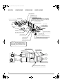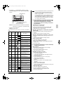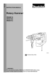
1
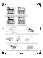
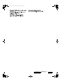
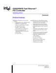
3P130767-1_Cover.fm Page 1 Friday, December 12, 2003 11:30 AM
MANUALE D’USO
OPERATION MANUAL
Scambiatore totale di calore
HRV (Ventilazione per recupero del calore) -con bobina DXTotal Heat Exchanger
HRV (Heat Reclaim Ventilation) -with DX CoilMODELLI
(Tipo a condotto montato sul soffitto)
MODELS
(Ceiling mounted duct type)
Con bobina DX & apparecchio umidificatore
With DX coil & Humidifer
VKMP50GMR
VKMP80GMR
VKMP100GMR
Italiano
English
3P130767-1_illust.fm Page 0 Friday, December 12, 2003 9:26 AM
HRV
HRV; Ventilazione per recupero del calore
• Grazie di aver acquistato questo scambiatore di calore
totale Daikin.
Prima di usare lo scambiatore di calore totale, leggere con
attenzione questo manuale d’istruzioni. Esso insegna il
modo corretto di utilizzare l’unità e fornisce consigli, nel
caso si verifichino dei problemi. Il manuale si riferisce solo
all’unità interna. Usarlo insieme al manuale di istruzioni
dell’unità esterna. Dopo aver letto il manuale, conservarlo
per riferimenti futuri.
• Questa unità è un tipo opzionale di condizionatore d’aria a
sistema VRVII.
Normalmente deve essere usato insieme al condizionatore
d’aria per interni, sistema VRVII di tipo M.
(RXYQ, REYQ, RXQ)
È anche possibile utilizzare questa unità come sistema
indipendente.
• Per controllare l’unità, utilizzare il telecomando del condizionatore d’aria interno a sistema VRVII.
HRV; Heat Reclaim Ventilation
• Thank you for purchasing this Daikin total heat exchanger.
Carefully read this operation manual before using the total
heat exchanger. It will tell you how to use the unit properly
and help you if any trouble occurs. This manual explains
about the indoor unit only. Use it along with the operation
manual for the outdoor unit. After reading the manual, file it
away for future reference.
• This unit is an option type for the VRVII system air conditioner.
It should normally be used in combination with the M-type
VRVII system indoor air conditioner. (RXYQ, REYQ, RXQ)
It is also possible to use this unit as a independent system.
• Use the remote controller of the VRVII-system indoor air
conditioner to control the unit.
3P130767-1_illust.fm Page 1 Friday, December 12, 2003 9:26 AM
MODELS
VKMP50GMR
VKMP80GMR
VKMP100GMR
(1) Hanger bracket
(7) Maintenance cover
(8) Heat exchanger elements
(3) Exhaust fan
It exchanges the heat (temperature and humidity)
from indoors with the air taken in from outdoors,
changes the outside air to the same condition as
indoors and then brings it indoors.
(2) Duct connecting flange
(6) Electric parts box
(12) Gas pipe
(13) Liquid pipe
(5) Damper
(16) Strainer (included)
(4) Air filter (Long life filter)
(14) Drain outlet
(10) Air supply fan
(19) Remote controller (Optional accessory)
(9) Name plate
(15) Humidifier (Natural evaporating type)
(11) Direct expansion coil
Important
Sometimes when first using the unit, the
smell of the heat exchanging element may
be noticeable, but it is not harmful. The smell
will gradually go away as the unit is used.
(11) Direct expansion coil
(17) Feed water tank
(20) Damper motor
(21) EA
Exhaust air
to outdoors
(22) OA
Fresh air
from outdoors
(outdoor air)
(23) RA
Return air
from room
(24) SA
Supply air
to room
(18) Solenoid valve
(15) Humidifier (Natural evaporating type)
1
[1]
3P130767-1_illust.fm Page 2 Friday, December 12, 2003 9:26 AM
• Combined operation system
with VRV systems
Indoor unit
HRV-With DX Coil-
Remote controller
for indoor unit
Outdoor unit
• Independent system
HRV-With DX Coil-
Outdoor unit
Remote controller
for indoor unit
Remote controller for VRV BRC1A61, 62
3
2
NOT
AVAILABLE
Remote controller for VRV BRC1C61
4
3
4
4
1
1
2
3
Remote controller for VRV BRC1C61
Remote controller for VRV BRC1A61, 62
5
[2]
5
3P130767-1_illust.fm Page 3 Friday, December 12, 2003 9:26 AM
1,2,3
1,2,3
Remote controller for VRV BRC1A61, 62
6
Remote controller for VRV BRC1C61
6
1
1
3
2
3
Remote controller for VRV BRC1A61,62
7
2
Remote controller for VRV BRC1C61
7
(1) Air filter
8-2
8-1
9
10
(1) Heat exchanger
element (×2)
(2) Handle
(3) Rail
11
12
[3]
3P130767-1_En.fm Page 1 Wednesday, December 17, 2003 7:39 PM
With DX coil & Humidifer
VKMP50GMR
VKMP80GMR
VKMP100GMR
Total Heat Exchanger
HRV (Heat Reclaim Ventilation) -with DX Coil-
CONTENTS
1.
2.
3.
4.
5.
1.
ILLUSTRATIONS................................................... [1][2][3]
SAFETY CAUTIONS ....................................................... 1
WHAT TO DO BEFORE OPERATION............................. 3
OPERATION PROCEDURE............................................ 6
MAINTENANCE (for a qualified service person only) ..... 8
TROUBLE SHOOTING.................................................... 9
Operation manual
• Keep all flames away if the refrigerant leaks.
The refrigerant in the air conditioner is safe and normally
does not leak. If the refrigerant leaks inside the room, the
contact with a fire of a burner, a heater or a cooker may
result in a harmful gas. Extinguish all flames from burning
appliances (such as stoves, heaters, etc.) ventilate the
room, and contact your dealer. Do not use the air conditioner until when a service person confirms to finish repairing the portion where the refrigerant leaks.
SAFETY CAUTIONS
Read the following cautions carefully and use your equipment
properly.
This unit comes under the term “appliances not accessible to
the genetic public.”
There are two kinds of safety cautions and tips listed here as follows:
WARNING............... Improper handling can lead to such
serious consequences as death or
severe injury.
CAUTION................ Improper handling can lead to injury or
damage. It could also have serious
consequences under certain conditions.
NOTE
• These instructions will ensure proper use of the equipment.
Be sure to follow these important safety cautions.
Keep these warning sheets handy so that you can refer to
them if needed.
Also, if this equipment is transferred to a new user, make sure
to hand over this user’s manual to the new user.
WARNING (During Operation)
• Never inspect or service the unit by yourself.
Ask a qualified service person to perform this work. (The
qualified service person)
• In order to avoid electric shock, fire or injury, or if you
detect any abnormality such as smell of fire, turn off
power and call your dealer for instructions.
• It is not good for your health to expose your body to the
air flow for a long time.
• Do not operate the unit with a wet hand.
An electric shock may result.
• Open the windows and ventilate the room if flammable
gas is leaked.
Insufficient ventilation when the unit is turned on or off may
cause an explosion from sparks at the electrical connection.
• Do not wash the HRV unit with water.
Electric shock or fire may result. (Not including air filters,
etc.)
• Be sure to stop the unit and turn off the power when
cleaning or inspecting it.
As the fan is rotating at high speed, it will cause injury.
CAUTION (During Operation)
• Do not use the HRV unit for other purposes.
In order to avoid any quality deterioration, do not use the
unit for cooling precision instruments, food, plants, animals
or works of art.
• Do not use burning appliances directly in the path of the
air from the unit.
Incomplete combustion of the burning appliances may
occur.
• Never expose little children, plants or animals directly
to the air flow.
Adverse influence to little children, animals and plants may
result.
• Neither place a flammable spray bottle near the HRV
unit or indoor intake and outlet grills nor perform spraying.
Doing so may result in a fire.
• Turn off the power when the unit is not to be used for
long periods of time.
Otherwise, the unit may get hot or catch on fire due to dust
accumulation.
• Do not block the intake or outlet grills.
If the fan does not blow air throughout the entire room it may
cause machine trouble.
• Always use the air filter.
If the air filter is not used, heat exchange elements will be
clogged, possibly causing poor performance and subsequent failure.
• Use gloves when cleaning.
Cleaning without gloves may cause injury.
• Do not use benzene or thinner to clean the outside surfaces of the air conditioner.
This may cause cracks, discoloration, or machine trouble.
• Do not operate the HRV unit in Bypass mode when the
room air is under heating in winter or when the outside
temperature is 30°C or higher.
This may cause condensation to form on the main unit or on
discharge grill, or around air supply opening.
• Do not operate the remote controller with wet hands.
This may cause electric shock.
• Never touch the internal parts of the controller.
Do not remove the front panel. Some parts inside are dangerous to touch, and a machine trouble may happen. For
checking and adjusting the internal parts, contact your
dealer.
• Do not change operations suddenly.
It can result not only in malfunction but also failure of
switches or relays in the remote controller.
1
English
3P130767-1_En.fm Page 2 Wednesday, December 17, 2003 7:39 PM
• Never press the button of the remote controller with a
hard, pointed object.
The remote controller may be damaged.
• Do not let any kind of sprays get on the remote controller (insecticides, cleaning materials, etc.)
This may cause breakage, deformation, or malfunction.
• Do not wipe the controller operation panel with benzine,
thinner, chemical dustcloth, etc.
The panel may get discolored or the coating peeled off. If it
is heavily dirty, soak a cloth in water-diluted neutral detergent, squeeze it well and wipe the panel clean. And wipe it
with another dry cloth.
• For refrigerant leakage, consult your dealer.
When the HRV unit is to be installed in a small room, it is
necessary to take proper measures so that the amount of
any leaked refrigerant does not exceed the limiting concentration even when it leaks. If the refrigerant leaks exceeding
the level of limiting concentration, an oxygen deficiency accident may happen.
• Do not install the HRV unit at any place where flammable gas may leak out.
If the gas leaks out and stays around the unit, a fire may
break out.
CAUTION (For installation)
WARNING (For installation)
• Do not attempt to install the unit yourself.
Ask your dealer for installation of the unit.
Incomplete installation performed by yourself may result in a
water leakage, electric shock, and fire.
• Installation should be done following the installation
manual.
Incorrect installation may cause leaking, electric shock, or
fire. Injuries may result if the unit falls.
• Do not install the unit in locations where the temperature in the areas around the unit or indoor intake and
outlet grills may fall below freezing.
The water pipes, humidifier element, solenoid valves, and
other components may freeze, causing breakage and leaks.
• Do not allow exhaust air to enter the outside air intake
vent.
This may cause the interior of the room to become contaminated and harming the health.
• Locate the outside air intake vent so that it does not
take in exhaust air which contains combustion air, etc.
Incorrect installation may cause a loss of oxygen in the
room, leading to serious accidents.
• All wiring must be performed by an authorized electrician.
To do wiring, ask your dealer. Never do it yourself.
• Make sure that a separate power supply circuit is provided for this unit and that all electrical work is carried
out by qualified personnel according to local lows and
regulations.
Insufficient power circuit capacity or incorrect work may
cause electric shock or fires.
• Be sure the unit is electrically earthed.
In order to avoid electric shock, make sure that the unit is
grounded and that the earth wire is not connected to gas or
water pipe, lightning conductor or telephone earth wire.
Install a wiring interrupter or ground-fault circuit interrupter
for the power wiring.
• Install the unit on a foundation strong enough to withstand the weight of the unit.
A foundation of in sufficient strongth may result in the unit
falling and causing injuries.
• Connect the remote controller to the correct model.
This may cause electric shock or fire.
• Do not move or attempt to re-install the remote controller yourself.
Incorrect installation, may cause electric shock or fire. Contact your dealer to have such work done.
English
• Do not use the HRV unit or an air suction/discharge
grille in the following places.
1. Place subjected to high temperature or direct flame.
Avoid a place where the temperature near the HRV unit
and the air suction/discharge air grille exceeds 40°C. If
the unit is used at high temperature, deformed air filter
and heat exchange element or burned motor result.
2. Place such as bathroom subjected to moisture.
Electric leak or electric shock and other failure can be caused.
3. Place such as kitchens or other places where oil
fumes are present.
This may cause fire.
4. Place subjected to much carbon black.
Carbon black attaches to air filter and heat exchange element, marking them unable to use.
5. Place such as machinery plant and chemical plant
where gas, which contains noxius gas or corrosive
components of materials such as acid, alkali, organic
solvent and paint, is generated.
Place where combustible gas leakage is likely.
This may cause gas poisoning or fires.
• Is a show protection measure taken?
For detail, consult your dealer.
• In order to avoid electric shock or fire, make sure that
an earth leakage breaker is installed.
No installation may cause electrical shock and fire.
• Make sure the temperature and the humidity of the installation location is within the usage range, not exceed the limit.
Do not install in cold storage or other locations with low temperatures or near heated pools. This may cause fires or
short circuits.
• Install the two outdoor ducts with down slope to prevent rainwater from entering the unit.
If this is not done completely, water may enter the building,
damaging furniture, and cause electric shock and fire.
• Insulate the two outdoor ducts to prevent dew condensation (and the indoor duct as well if needed).
If this is not done completely, water may enter the building,
damaging furniture, etc.
• Use electric insulation between the duct and the wall
when using metal ducts to pass metal or wire laths or
metal plating into wooden buildings.
This may cause electric shock, short circuits, or fire.
• Arrange the drain hose to ensure smooth drainage.
Incomplete drainage may cause wetting of the building, furniture etc.
• Do not install the remote controller in locations where
the temperature exceeds the range between 0°C and
35°C and the humidity exceeds the range between RH
40% and 80%.
Electrocution or breakdown may occur.
2
3P130767-1_En.fm Page 3 Wednesday, December 17, 2003 7:39 PM
• Do not place the controller exposed to direct sunlight.
The LCD display may get discolored, failing to display the
data.
• Avoid placing the controller in a spot splashed with
water.
Water coming inside the controller may cause an electric
leak or may damage the internal electronic parts.
• Never pull or twist the electric wire of a remote controller.
It may cause the unit to malfunction.
(For moving and reinstalling/
WARNING repairing)
• Do not modify the unit.
This may cause electric shock or fire.
• Ask your dealer to move and reinstall the unit.
Incomplete installation may result in a water leakage, electric shock, and fire.
• Do not disassemble or repair the unit yourself.
This may cause electric shock or fire.
Contact your dealer to have such work done.
• When removing the unit, be sure not to tip it.
The water inside the unit may drip or leak out, and get on
furniture, etc.
2.
WHAT TO DO BEFORE OPERATION
This operation manual is for the following systems with standard control. Before initiating operation, contact your Daikin
dealer for the operation that corresponds to your system type
and mark.
If your installation has a customized control system, ask your
dealer for the operation that corresponds to your system.
2-1 NAMES OF PARTS (Refer to figure 1)
(1)
(2)
(3)
(4)
(5)
(6)
(7)
(8)
(9)
(10)
(11)
(12)
(13)
(14)
(15)
(16)
(17)
(18)
(19)
(20)
(21)
(22)
(23)
(24)
Hanger bracket
Duct connecting flange
Exhaust fan
Air filter (Long life filter)
Damper
Electric parts box
Maintenance cover
Heat exchanger elements
Name plate
Air supply fan
Direct expansion coil
Gas pipe
Liquid pipe
Drain outlet
Humidifier (Natural evaporating type)
Strainer (included)
Feed water tank
Solenoid valve
Remote controller (Optional accessory)
Damper motor
EA Exhaust air to outdoors
OA Fresh air from outdoors
RA Return air from room
SA Supply air to room
2-2 REMOTE CONTROLLER AND CHANGEOVER
SWITCH: NAME AND FUNCTION OF EACH
SWITCH AND DISPLAY
(Refer to figure 3 and 4)
• Only the items marked with an asterisk (∗ mark) are explanation relating to the functions and display of the unit.
Unmarked items are functions of the combined air conditioners. When using buttons for functions which are not available (buttons which are not described in the text) will cause
“NOT AVAILABLE” to be displayed.
Contact your dealer for more detailed descriptions of those
functions (buttons).
∗1 On/off button
Press the button and the system will start. Press the button
again and the system will stop.
∗2 Operation lamp (red)
The lamp lights up during operation.
∗3 Display “
” (changeover under control)
May be displayed when combined with a VRV-system air
conditioner.
It is impossible to changeover heat/cool with the remote
controller when this icon is displayed.
” (air flow flap)
4 Display “
This displays the direction and mode of the air flow flap of
the combined air conditioner.
5 Display “
” (ventilation/air cleaning)
This display shows that the total heat exchange and the air
cleaning unit are in operation. (these are optional accessories)
6 Display “
C ” (set temperature)
This displays the set temperature of the combined air conditioner.
It is not displayed when the unit is used as an independent
system.
”“
”“
”“
”“
” (operation
7 Display “
mode)
This displays the operating status of the combined air conditioner.
• There is no “heating” for the VRVII system (Cooling only
type).
• “
” is only available for systems operating in cooling
and heating at the same time.
” (programmed time)
∗8 Display “
This display shows the programmed time of the system
start or stop.
9 Display “
TEST ” (inspection/test operation)
When the inspection/test operation button is pressed, the
display shows the mode in which the system actually is.
• Do not use under usual use (service person/installer only).
10 Display “
” (under centralized control)
When this display shows, the system is under centralized
control. (This is not a standard specification.)
” (fan speed)
∗11 Display “
This display shows the fan speed you have selected.
∗ This is only displayed when the fan speed selection button is pressed. It normally displays the set fan strength of
the combined air conditioner.
” (time to clean air filter)
∗12 Display “
Refer to “4-1 HOW TO CLEAN THE AIR FILTER”.
13 Display “
” (defrost/hot start)
It may be displayed when the combined air conditioner is in
heating mode.
3
English
3P130767-1_En.fm Page 4 Wednesday, December 17, 2003 7:39 PM
∗14 Timer mode start/stop button
Refer to the chapter “Operation procedure Programming start and stop of the system with timer.”
(Refer to page 7 (3-3))
2-3 Explanation for SYSTEMS
∗15 Timer on/off button
Refer to the chapter “Operation procedure Programming start and stop of the system with timer.”
(Refer to page 7 (3-3))
∗16 Inspection/test operation button
Pressed during inspection or “test run.”
• Do not use under usual use. (service person/installer only)
∗17 Programming time button
Use this button for programming start and/or stop time.
! OPERATION for EACH SYSTEM
18 Temperature setting button
Use this button for setting the desired temperature of air
conditioner combined with this unit.
∗19 Filter sign reset button
Refer to “4-1 HOW TO CLEAN THE AIR FILTER”.
20 Fan speed control button
Press this button to select the fan speed of air conditioner
combined with this unit.
∗21 Operation mode selector button
Press this button to select the operation mode of air conditioner combined with this unit.
22 Air flow direction adjust button
Press this button to select the air flow direction of air conditioner combined with this unit.
23 Fan only/air conditioning selector switch
Set the switch to “
” for fan only operation or to “
for heating or cooling operation.
24 Cool/heat changeover switch
Set the switch to “
” for cooling or to “
operation.
This unit can be made a part of two different systems: as
part of the combined operation system used together with
VRVII SYSTEM Air Conditioners and as the independent
system using only the HRV. An operating remote controller
is required when using the unit as an independent system.
Ask your dealer what kind of system your system is set up
for before operation.
For the operation of the remote controller for indoor unit
and centralized controller, refer to the instruction manual
provided with each unit.
See the included operating manuals for details on how to
operate each remote control.
Sample system (Refer to figure 2)
Combined operation system with VRVII systems
[Operation]
The air conditioner remote controller stars and stops the air
conditioner and the HRV unit.
You can also select the ventilation amount and the ventilation mode.
During intermediate periods when only the HRV unit is used
without the air conditioner, select “ventilation” with the operation selection button.(Refer to 2-4.)
Sample system (Refer to figure 2)
Independent system
[Operation]
The HRV unit can be started and stopped using the remote controller.
You can also select the ventilation amount and the ventilation mode.
2-4 ABOUT DIRECT DUCT CONNECTION SYSTEM
Installation Examples
Direct duct connection system
”
” for heating
25 Remote controller thermo
This detects the temperature around the remote controller.
This is not the same as the temperature of return air from
room (RA) by heat exchanger unit.
(HC0007)
Independent duct system
∗26 Display “
”“
”“
”
This displays the ventilation mode. (BRC1C61 and so on.)
(This is not displayed on the controller BRC1A61, 1A62)
∗27 Display “NOT AVAILABLE”
• “NOT AVAILABLE” may be displayed for a few seconds if
the function for the button pressed is not available for the
unit or the air conditioner.
• “NOT AVAILABLE” is only displayed when none of the
indoor units is equipped with the function in question when
running several units simultaneously. It is not displayed if
the function is available on even one of the units.
∗28 Ventilation fan mode selector button (available only
connecting the HRV unit)
This is pressed to switch the fan mode of the HRV unit.
∗29 Ventilation fan speed control button (available only
connecting the HRV unit)
This is pressed to control the fan speed of the HRV unit.
(Refer to item 11)
NOTE
• In contradistinction to actual operating situations, the display
on figure 3 shows all possible indications.
• If the filter sign lamp lights up, clean the air filter as explained in
the chapter “MAINTENANCE”. After cleaning and reinstalling
the air filter: press the filter sign reset button on the remote controller. The filter sign lamp on the display will go out.
English
(HC0008)
The HRV unit cannot be operated independently when the
air conditioner is connected to the HRV unit via a duct.
When using the HRV unit, set the air conditioner to “fan”
mode on weak fan strength.
Operation mode display
“Ventilation” is displayed.
Operation mode
selector button
hr
hr
TEST
NOT
AVAILABLE
TEST
Remote controller
for indoor unit
4
3P130767-1_En.fm Page 5 Wednesday, December 17, 2003 7:39 PM
• Each time you press the operation selection button, the
operation mode display will change as shown in the figure
below.
Example 1:
In case of the remote controller “BRC1C61” and as equivalent.
Display changes as below.
When air conditioner and HRV
unit are not connected via duct
<Operation mode>
VRV:
Cooling mode
HRV:
Heat exchange mode
VRV:
Fan mode
HRV:
Heat exchange mode
VRV:
Stopping
HRV:
Heat exchange mode
Example 2:
In case of the remote controller “BRC1A61,62”
Display changes as below.
When air conditioner and HRV
unit are not connected via duct
<Operation mode>
VRV:
Cooling mode
HRV:
Heat exchange mode
VRV:
Fan mode
HRV:
Heat exchange mode
VRV:
Stopping
HRV:
Heat exchange mode
When air conditioner and HRV
unit are connected via duct
When air conditioner and HRV
unit are connected via duct
<Operation mode>
VRV:
Cooling mode
HRV:
Heat exchange mode
VRV:
Fan mode
HRV:
Heat exchange mode
<Operation mode>
VRV:
Cooling mode
HRV:
Heat exchange mode
VRV:
Fan mode
HRV:
Heat exchange mode
NOTE) Current Ventilation mode doesn’t be displayed.
NOTE) Current Ventilation mode can be visible and
selected on the remote controller.
5
• When the display shows “
” (time to clean air filter), ask a
qualified service person to clean the filters (Refer to the
chapter “MAINTENANCE”).
English
3P130767-1_En.fm Page 6 Wednesday, December 17, 2003 7:39 PM
3.
! EXPLANATION OF OPERATION MODE
OPERATION PROCEDURE
3-1 COOLING, HEATING, AND FAN ONLY OPERATION (Refer to figure 5)
Cooling mode
Heating mode
[PREPARATIONS]
• To protect the unit, turn on the main power switch 6 hours
before operation.
Do not turn off the power during the heating or cooling season. This is to ensure smooth start-up.
Press the operation mode selector button several times
and select the operation mode of your choice;
1
“
” Cooling operation
“
” Heating operation
“
” Fan only operation
Automatic mode
It automatically
selects “
” or
“
While operating in ventilation mode, the
unit adjusts the outside air to the indoor
temperature and then brings it into the
room.
.”
Fan mode
It only operates in
ventilation mode.
The unit processes outside air
using the heat
exchanger element, but not the
DX expantion coil.
NOTE
NOTE
• “
” can only be set for systems operating in cooling and
heating at the same time.
• This unit cannot control room temperature. If this is needed,
do not install the HRV unit alone, but rather install another
indoor unit.
“
” is displayed on all remote controllers when
using the VRVΙΙ system cooling only type, but only “
” and
“
” can be set.
• Select the operating mode on a remote controller on which
“
” is not displayed.
“
”“
” and “
” (only for simultaneous cooling/heating systems) cannot be selected on remote controllers on
which it is displayed.
See 3-2 if “
2
Press ventilation fan mode button if you wish to change
the fan mode.
The display rotates through the following selections
every time the button is pressed.
Automatic mode
3
” is displayed.
Heat exchange mode
Bypass mode
Press ventilation fan speed button if you wish to change
the fan speed.
The display rotates through the following selections
every time the button is pressed.
L
H
After the selection, the ventilation fan speed display disappears.
And the fan speed of the combined air conditioner requlary displays.
4
Automatic mode
: When combined with a VRVΙΙ-system
air conditioner
The unit automatically switches
between “
” and “
” based on
information from the VRVΙΙ system air
conditioner (heating, cooling, fan, and
set temperature) and information from
the HRV unit (indoor and outdoor temperatures).
The unit automatically switches between
“
” and “
” when it is combined
with an air conditioner (Not producted
by Daikin) and based on only the information from the HRV unit (indoor and
outdoor temperatures) when the HRV
unit is operating alone.
Total heat exchange mode
: Outdoor air passes through
the heat exchange element
and heat exchanged air is
sent into the room.
Bypass mode
: In this mode outdoor air does not through
the heat exchange element, but rather
sent into the room as is.
! EXPLANATION OF HEATING OPERATION
High
Low
! EXPLANATION OF VENTILATION MODE
Press the on/off button.
The operation lamp lights up and the system starts operation.
Stopping the system
Press start/stop one more time. The operation lamp will go off.
The unit will stop.
Defrost operation
• In heating operation, freezing of the outdoor unit coil increases.
Heating capabitity decreases and the system goes into defrost
operation.
• The remote controller will read “
” until the hot air
starts blowing.
• It returns to the heating operation again after 6 to 8 minutes
(10 at the longest).
Hot start
• The remote controller will read “
” until the hot air
starts blowing, e.g. at the start of heating operation.
• After stopping operation, the fan may continue operating for
up to a minute.
• The fan may stop, but this is not a malfunction.
NOTE
• Do not turn off the power immediately after operation stops.
Wait at least 5 minutes.
Not waiting may cause leaking or malfunction.
English
6
3P130767-1_En.fm Page 7 Wednesday, December 17, 2003 7:39 PM
3-2 SETTING THE MASTER REMOTE CONTROLLER (Refer to Fig. 6)
• When the system is installed as shown bellow it is necessary to designate one of the remote controllers as the master remote controller.
• Only the master remote controller can select cooling, heating, or automatic operation (the last only on simultaneous
cooling/heating systems).
• The displays of slave remote controllers show “
”
(changeover under control) and they automatically follow the
operation mode directed by the master remote controller.
• “
• The ventilation mode can be changed regardless of the setting (main or slave).
NOTE
• This unit cannot control room temperature. If the unit is connected to the same system with other indoor units, set the
master remote controller on the other indoor units.
2
However, it is possible to changeover to program dry with slave
remote controllers if the system is in cooling operation set by the
master remote controller.
(Cooling/heating selection operation systems)
” flashes when the power is first turned on.
3
When multiple indoor units
or this unit are connected to
a single outdoor unit.
Press the operation mode selector button of the controller that you wish to designate as the master remote controller. Then designation is completed. This remote
controller is designated as the master remote controller
and the display showing “
” (changeover
under control) vanishes.
The displays of other remote controller show
“
” (changeover under control)
Press the operation mode selector button on the master
remote controller (i.e. a remote controller which does not
display “
”) to scroll through the modes.The
display will scroll through “ ” – “
” (only for simultaneous cooling/heating systems) – “ ” – “ ”.
The display on slave remote controllers will also change
automatically.
! Details and activity of operation
HRV-with DX coil-
Indoor unit
One of these remote controllers can be
designated as the master remote
controller.
1. Setting the master remote controller (without the
“
” display) to cooling/heating mode will make
slave remote controllers (with the “
” display) to
follow to the mode of the master remote controller.
• Selection of fan mode is possible, however.
2. Setting the master remote controller (without the
“
” display) to fan mode will make slave remote
controllers (with the “
than fan mode impossible
(Simultaneous cooling/heating systems)
If multiple indoor units or many
of this unit are connected to
outdoor unit via BS unit.
BS unit:
This is the unit which
selects cooling and
BS unit
heating.
HRV
-with DX coil-
HOW TO DESIGNATE THE MASTER REMOTE CONTROLLER
1
3-3 PROGRAMMING START AND STOP OF THE
SYSTEM WITH TIMER (Refer to figure 7)
• The timer is operated in the following two ways.
Programming the stop time “
”. The system stops
operating after the set time has elapsed.
Programming the start time “
”. The system starts
operating after the set time has elapsed.
• The start and the stop time can be simultaneously programmed.
Indoor unit
One of these remote controllers can be
designated as the master remote
controller.
Press the operation mode selector button of the current
master remote controller for 4 seconds.
The display showing“
” (changeover under
controll) of all slave remote controllers connected to the
same outdoor unit or BS unit flashes on.
” display) any setting other
1
Press the timer mode start/stop button “
times and select the mode on the display.
• For setting the timer stop “
” several
”
• For setting the timer start “
”
Each time the button is pushed, the indication changes
as shown below.
“No indication”
“
”
“
”
OPTION
C
NOT
7
H
English
3P130767-1_En.fm Page 8 Wednesday, December 17, 2003 7:39 PM
Press the programming time button and set the time for
stopping or starting the system.
2
Each time this button is pressed, the time
advances or goes backward by 1 hour.
• The timer can be programmed for a maximum of 72 hours.
• Each time when “
” is pushed, the time advances one hour.
Each time when “
” is pushed, the time goes back one hour.
Press the timer on/off button.
3
The timer setting procedure ends. The display
“
” or “
” changes from flashing light to
constant light.
• After the timer is programmed, the display shows the
remaining time.
For cancelling the timer operation, push the timer on/off
button “
” once again.
The indication disappears.
NOTE
• When setting the timer off and on at the same time,
repeat the above procedure (from “ 1 ” to “ 3 ”)
once again.
4.
MAINTENANCE
(for a qualified service person only)
ONLY A QUALIFIED SERVICE PERSON IS ALLOWED TO
PERFORM MAINTENANCE
WARNING
• BEFORE OBTAINING ACCESS TO TERMINAL DEVICES,
ALL POWER SUPPLY CIRCUITS MUST BE INTERRUPTED.
• To clean the HRV, or maintenance be sure to stop operation,
and turn the power switch off. It may cause electrical shock
and it is very dangerous to touch the rotating part.
• Do not wash the HRV with water.
Doing so may result in an electric shock.
CAUTION
• Use gloves when cleaning.
Cleaning without gloves may cause injury.
• Watch your step.
Use caution, as this requires working in high places.
! DETAIL EXPLANATION
4-1 HOW TO CLEAN THE AIR FILTER
When you want to stop operation after a desired time,
Example:
Set the time to “8”.
↓
Clean the air filter when the display shows “
CLEAN AIR FILTER).
“
8hr
” will display.
Stops operation 8 hours after the reservation is complete.
The program will be cleared after the operation stops.
• Set the stop time during operation.
When you want to start operation after a desired time has
elapsed
Example:
Set the time to “8”.
↓
“
8hr
” will display.
Starts operation 8 hours after the reservation is complete.
The reservation is cancelled after operation starts.
• Set the start time while the unit is stopped.
• The remaining time will count at the same time after reservation is complete.
See the example below if you want to reserve “off after time”
and “on after time” at the same time.
For example: (Refer to figure below)
When the timer is programmed to stop the system after 3 hours
and start the system after 4 hours, the system will stop after 3
hours and start 1 hour later.
Example:
hr
hr
• Setting “off after 3 hours” and “on after 4 hours” will
↓
” (TIME TO
It will display that it will operate for a set amount of time.
AT LEAST ONCE EVERY YEARS (FOR GENERAL OFFICE
USE)
(CLEAN THE MORE FREQUENTLY IF NECESSARY.)
• Increase the frequency of cleaning if the unit is installed in a
room where the air is etermely contaminated.
• If the dirt becomes impossible to clean, change the air filter
(Air filter for exchange is optional).
1. Detach the maintenance cover.
Go into ceiling through the inspection hatch, remove binding
metal of maintenance cover and take it off.
(Refer to figure 8-1)
2. Detach the air filter.
Take out from the heat exchange elements.
(Refer to figure 8-2)
3. Clean the air filter. (Refer to figure 9)
Use vacuum cleaner A) or wash the air filter with water B).
A) Using a vacuum cleaner
B) Washing with water
When the air filter is very dirty, use soft brush and neautral detergent.
After cleaning, remove water and dry in the shade.
NOTE
• Do not wash the air filter with hot water of more than 50°C,
as doing so may result in discoloration and/or deformation.
• Do not expose the air filter to fire, as doing so may result in
burning.
• Do not use gasoline, thinner, or other organic solvents.
This may cause discoloration or deformation.
4. Fix the air filter.
If the air filter is washed, remove water completely and allow
to dry for 20 to 30 minutes in the shade. When dried completely, install the air filter back in place.
(Refer to figure 10)
• Operation will stop after 3 hours.
Operation will then start in 1 hour from the time it stopped.
English
8
3P130767-1_En.fm Page 9 Wednesday, December 17, 2003 7:39 PM
NOTE
• Be sure to install the air filter after servicing.
(Missing air filter causes clogged heat exchange element.)
The air filter is an optional item and the replacement is
available.
5. Install the maintenance cover.
Refer to page 8 (4-1, 1).
For remote controllers which display the filter sign,
turn on the power after maintenance, and press the
filter sign reset button.
∗ Consult your dealer if you want to change the time setting
for when the filter sign goes on.
4-3 INSPECTION AND MAINTENANCE OF THE
HUMIDIFIER
Have your dealer do the following inspections in order to
get the longest use. Once a year is recommended.
For dealers
Content of maintenance
Problems if
Inspected
maintenance
Items to be
part
is not carried
Solution
inspected
out
Strainer
(80-mesh)
NOTE
• Do not remove the air filter except when cleaning.
Breakdown may occur.
4-2 HOW TO CLEAN THE HEAT EXCHANGE ELEMENT
CAUTION
• Do not clean touching strongly with a vacuum cleaner. This
may crush the mesh of the heat exchange elements.
• Never wash the heat exchange element with water.
• Have your dealer professionally clean the filter if it is very
dirty.
5. Put the heat exchange element on the rail and insert it
securely in place.
6. Install the air filter securely in place. (Refer to page 8 (4-1, 4))
7. Install the maintenance cover securely in place.
(Refer to page 9 (4-1, 5))
Insufficient
humidifying.
Check o-ring
for cracks
Replace if
cracked.
Leaking.
Check for
operation of
float switch
Clean if it
does not
work properly
due to buildup.
Insufficient
humidifying.
Overflowed
feed water
tank.
Clean if very
dirty.
Weak fan
strength.
Reduced
humidifying
capacity.
Replace if it
doesn’t work.
Insufficient
humidifying.
Overflowed
feed water
tank.
Check for dirt
WARNING
1. Detach the maintenance cover.
Refer to page 8 (4-1, 1).
2. Detach the air filter.
Refer to page 8 (4-1, 2).
3. Take out the heat exchange elements.
Pull out the air filter and then pull out the two heat
exchanger elements. (Refer to figure 11)
4. Use a vacuum cleaner to remove dust and foreign objects
on the surface of the heat exchange element.
(Refer to figure 12)
• Use the vacuum cleaner equipped with a brush on the
tip of the suction nozzle.
• Lightly contact the brush on the surface of the heat
exchange element when cleaning.
(Do not crush the heat exchange element while cleaning.)
Clean if
clogged.
Feed water
tank
AT LEAST ONCE EVERY TWO YEARS
(FOR GENERAL OFFICE USE)
(CLEAN THE ELEMENT MORE FREQUENTLY IF NECESSARY.)
• Please exchange the heat exchange element if you find
that the knob of the heat exchange element is damaged
or is deteriorated when cleaning it.
There is falling danger.
Check for
clogging
Solenoid
valve
Check for
shutting and
opening.
Check in a
similar fashion when
checking the
float switch
operation.
4-4 REPLACING THE HUMIDIFIER ELEMENT
• The humidifier element needs to be replaced regularly.
The humidifier element should in general be replaced once
every three years when supply water is soft water, but outside factors (water quality, hard water, etc.) as well as operating conditions (24-hour-a-day air conditioning, etc.) may
shorten its productive life.
• Contact your dealer if you have any questions.
5.
TROUBLE SHOOTING
5-1 If one of the following malfunctions occurs,
take the measures shown below and contact
your Daikin dealer.
The system must be repaired by a qualified service person.
WARNING
When the HRV is in abnormal conditions (smell of something burning, etc), cut off the power, and contact your
dealer.
Continued operation under such circumstances may result in a
failure, electric shock, and fire.
• If a safety device such as a fuse, a breaker, or an earth leakage breaker frequency actuates, or ON/OFF switch does not
properly work.
Measure: Do not turn the power on.
• The remote control buttons do not work well.
Measure: Turn off the main power switch.
9
English
3P130767-1_En.fm Page 10 Wednesday, December 17, 2003 7:39 PM
• If the display “
” (INSPECTION), ”UNIT No.” and the
OPERATION lamp flash and the “MALFUNCTION CODE”
appears.
OPERATION lamp
UNIT No.
In case of the malfunction with the code in white letters
on the black background in the unit still operates.
However, be sure to have it inspected and repaired
and as soon as possible.
If any of the above error codes are displayed, there is
a possibility that the problem in question has occurred
with a combined air conditioner or outdoor unit. See
the operation manuals included with the air conditioners or outdoor units for details.
H
INSPECTION
display
INDOOR UNIT No. in which
a malfunction occurs
MALFUNCTION CODE
Measure: Notify and inform the model name and what the
malfunction code indicates to your Daikin dealer.
• There are other malfunctions.
Measure: Stop the unit.
List of malfunction codes of Remote controller of the HRV-system
Operation
lamp
Inspec
tion
indicator
Unit
No.
Malfunction
code
On
Off
Blinking
64
Indoor air thermistor malfunction
On
Off
Blinking
65
Outdoor air thermistor malfunction
On
Off
Blinking
6A
Blinking
Blinking
Blinking
6A
Blinking
Blinking
Blinking
A1
On
Off
Blinking
A1
Blinking
Blinking
Blinking
A9
Electric expansion valve
drive error
Blinking
Blinking
Blinking
C4
Liquid piping thermistor error
(faulty connection, disconnection short circuit, fault)
Blinking
Blinking
Blinking
C5
Gas piping thermistor error
(faulty connection, cut wire,
short circuit, fault)
Blinking
Blinking
Blinking
C9
Intake air into coil thermistor error
(faulty connection, disconnection,
short circuit, fault)
Blinking
Blinking
Blinking
U3
Blinking
Blinking
Blinking
U5
Off
Blinking
Off
U5
Off
Blinking
Off
U8
Transmission error between
main remote controller and
sub remote controller
Off
Blinking
Blinking
UA
Incorrect combination with
indoor unit and remote controller.
On
Blinking
On
UC
Central control address over
lapping
Blinking
Blinking
Blinking
UE
Transmission error between
the unit and centralized controller
English
Description
Dumper-related malfunction
Dumper-related malfunction
+ thermistor malfunction
Printed circuit board fault
Printed circuit board fault
Test run not performed
Transmission error between
the unit and remote controller
Setting error of remote controller
5-2 If the system does not properly operate except
for the above mentioned case, and none of the
above mentioned malfunctions is evident,
investigate the system according to the following procedures.
1. The unit does not operate at all.
• Check if there is a power failure.
After power has been restored, start operation again.
• Check if the fuse has blown or breaker has worked.
Change the fuse or set the breaker.
2. Amount of discharged air is small and the discharging
sound is high.
• Check if the air filter and heat exchange element are
clogged.
Clean tha air filter and heat exchange element.
3. Amount of discharged air is large and so is the sound.
• Check if the air filter and heat exchange element are not
installed.
Install the air filter and heat exchange element.
4. It dries usually in winter.
• Is the water supply service valve open?
Open the water supply service valve.
• Have you lowered setting on the humidistat (locally procured) too far?
Correct the setting.
5-3 The following malfunctions must be cheched by
a qualified service person
1. Do not operate
• Are there any problems with the power or wiring?
Inspect the power and wiring.
• Are there any problems with the fan unit?
Inspect the fan motor and fan.
2. Humidifies very little or not at all.
• Is there water in the water supply tank?
1 Is water being supplied?
Inspect the water supply pipes and supply the water.
2 Is the strainer clogged?
Clean the strainer.
3 Is the solenoid valve broken (i.e. won’t open)?
Replace the solenoid valve.
4 Is the humidifier element torn?
Replace.
5 Has the water resistance of the humidifier element
dropped?
Replace the humidifier element.
6 Are the control circuits broken?
Replace the printed circuit board and other electric parts.
• Is the float switch broken?
Replace the float switch.
• Is the water supply pressure sufficient?
Re-set it so that there is sufficient pressure.
• Is there foreign matter in the feed water tank?
Clean the feed water tank.
10
3P130767-1_Cover.fm Page 2 Friday, December 12, 2003 11:30 AM
3P130767-1 EM03A089 (0311)
FS
HT