1
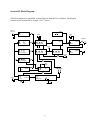
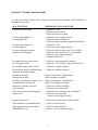
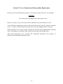
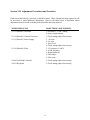
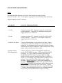
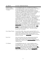
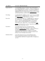
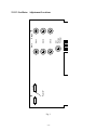
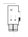
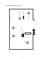
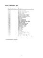
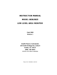
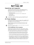
The
minimoog
MODEL D
TECHNICAL SERVICE MANUAL
by R. J. Folkman
CONTROLLERS
MIXER
MODIFIERS
OSCILLATOR BANK
moog
MUSIC INC.
the first sound in synthesizers
-1-
OUTPUT
MINI-MOOG
Field Service Manual
CONTENTS
Section
I
Title
Page
Precautionary Measures
2
II
Sub-assembly Descriptions
3
III
Block Diagram
5
IV
Trouble Analysis Guide
6
V
Sub-assembly Locations
8
Cover Removal and Sub-assembly Replacement
9
VI
VII
VIII
IX
X
XI
XII
XIII
Adjustment Procedures and Locations
10
Keyboard Maintenance
14
Schematic Diagrams
15
Component Location Charts
16
Replacement Parts
17
Modifications
18
Ordering and Shipping Instructions
19
Service Department Policy
20
7/73 RJF
-2-
Section I: Precautionary Measures
In the Mini-Moog, as in any electrical device, shock hazards exist. All lethal voltages are
confined to the area around the power switch and the A.C. fuseholder. Always unplug the
instrument while servicing the electronics. Keyboard cleaning and adjusting may be done with
the unit turned on.
When a fuse blows, replace it only with the proper size as indicated on the label directly below
the fuseholder. If the fuse continues to blow, it is an indication that a definite electrical problem
has developed. Never try a larger fuse; this will only result in further internal damage.
Avoid making adjustments at random. Each adjustment is critical and should be made in
accordance with the procedures outlined herein. If a sub-assembly is found to be defective, we
recommend exchanging it rather than attempting to repair it. Unless a qualified technician is
available, with special test fixtures, more harm than good may result and possibly void any
remaining warranty.
-3-
Section II: Sub-assembly Description
93-113 Oscillator (Board 1)
This assembly contains three tone oscillators, summing amplifiers, exponential current
generators, waveshaping circuits and a -5 volt reference source. The three oscillators are
independent and non-synchronous. Each oscillator is voltage controlled from external sources
such as the keyboard. Linear input voltages are converted to exponential currents which are used
to control the frequency or pitch of the tone produced. The basic sawtooth signal is processed to
derive triangle and variable width rectangular waveforms. Oscillator #3 has a wide range
capability which enables it to be used for modulation purposes. The -5 volt reference source is
used to establish the precise voltage steps on the octave range switches.
93-114 Contour Generator (Board 2)
This assembly contains two identical contour or envelope generators, and the keyboard circuitry.
Upon triggering, the contour generators produce a voltage envelope with variable attack, decay,
and sustain. The output is used to control the gain of the first voltage controlled amplifier or the
cutoff frequency of the voltage controlled filter.
The keyboard circuit contains a constant current source which feeds the keyboard resistor string.
This insures the proper voltage drop across each of the 43 keyboard resistors. Also contained on
this assembly is the sample-hold circuit which measures the voltage from the keyboard and
maintains it until a different key is depressed. The output of this circuit is the control voltage for
the oscillators and the filter. The glide feature is a function of the sample-hold circuit.
93-115 Power Supply (Board 3)
This assembly contains the plus and minus 10 volt regulators, the headphone amplifier, the noise
generator and the modulation mix amplifier. The plus supply uses a temperature compensated
zener diode for a voltage reference. The minus supply is referenced to the regulated plus voltage
causing the two supplies to "track". Both supplies employ remote voltage sensing for optimum
stability.
The headphone amplifier is an A.C. coupled emitter follower with a push-pull output. The noise
generator uses a reverse biased transistor junction for a noise source. The output of this
transistor is processed through three filter circuits to derive the white, pink, and red noise
outputs. The modulation mix amplifier takes signals from Oscillator #3 and the noise generator,
sums them and supplies an output which is used for modulation.
93-116 Filter (Board 4)
This assembly contains the voltage controlled filter, the external input pre-amplifier, the overload
lamp driver, the first and second voltage controlled amplifiers and the A-440 reference oscillator.
The filter is a voltage controlled low pass type which employs the Moog patented ladder
network. It is capable of regenerating (oscillating) over a wide frequency range. The scale is
adjustable so the filter can be set to track the keyboard.
-4-
The external pre-amp is a three transistor high-gain amplifier. The output of the pre-amp is
monitored by an overload indicator. The overload driver circuit is a Schmitt trigger which turns
the overload light on when external signal levels become excessive.
The first and second voltage controlled amplifiers are two nearly identical circuits. Their gain is
controlled by varying the voltage which supplies the current source transistors. A buffer or
output amplifier follows the second VCA stage.
The A-440 reference source is a highly stable Wein Bridge oscillator circuit. It produces a
somewhat imperfect sinewave which increases its harmonic content. These harmonics or
overtones assist in tuning to the reference, especially when the source being tuned is one or two
octaves away from the reference frequency. The output of this circuit is coupled to the VCA
buffer amplifier.
93-118 Rectifier Board
This assembly contains the input bridge rectifier diodes and the unregulated D.C. filter
capacitors.
93-060 Left Hand Controller
This assembly contains the PITCH wheel, MODULATION wheel, GLIDE and DECAY
switches, and two jacks for remote switching of glide and decay. The PITCH wheel has a
mechanical detent which allows it to be easily returned to a pre-set tune point.
To service this assembly, remove the two mounting screws and lift the unit out. All connections
to this assembly are through a 12 prong plug to simplify servicing and replacement.
93-061 Keyboard
The Mini-Moog keyboard is a standard three and one-half octave removable sub-assembly. All
electrical contacts are gold plated for high reliability. The keyboard is held in place by four (4)
mounting screws which are accessible when the bottom cover is removed. All connections to
this assembly are through a 6 prong plug to simplify servicing and replacement.
-5-
Section III: Block Diagram
(This block diagram is a simplified version of the one from the User’s Manual. The diagram
from the service manual fits on a single 11"x17" sheet.)
High-Z
Mic Input
A440
Mic Preamp
Vol
Pedal
Pedal
Main Out
OSC 1
8ve
Wave
VCF
VCA 1
VCA 2
Volume
Freq Emp Amt
S-Trig
Filter Contour
OSC 2
8ve Tune Wave
Rise
Loudness Contour
Sus Fall
Rise
Volume
Sus Fall
Decay Jack
Decay Switch
OSC 3
8ve Tune Wave
Mod
Roller
White
Noise
Source
Modulation
Mix
OSC
Control
Pedal
1/3
Mix
Pink
Tune
Keyboard
Portamento
Pitch Roller
Glide Switch
Glide Jack
-6-
Headphone
Amplifier
2/3
Section IV: Trouble Analysis Guide
Use this chart along with the block diagram (Section III) to determine which assembly or
component is defective.
MALFUNCTION
PROBABLE CAUSE AND CURE
Unit dead (no pilot light)
1. Blown A.C. fuse
2. Defective power switch
3. Defective line cord or plug
Unit dead (pilot light on,
overload light off)
1. Defective power supply (board 3)
2. Defective power transformer
3. Defective output amplifier (change filter board 4)
Unit dead (pilot light and
overload light on)
1. Blown D.C. fuse
2. Defective power supply (board 3)
Excessive hum and constant
modulation of all signals
1. Defective rectifier diode on 93-118 assembly
2. Defective filter cpacitor on 93-118 assembly
3. Defective power supply (board 3)
4. Broken ground wire
No output from any mixer source
(A-440 output works)
1. Defective contour generator (board 2)
2. Defective VCA or filter (replace filter board 4)
No oscillator output (noise works)
1. Defective oscillator (board 1)
One oscillator dead or malfunctioning,
other two operating normally
1. Defective oscillator (board 1)
Oscillators drift and
exhibit poor tracking
Refer to Section XII - Modifications
under Oscillator Assembly
Oscillator 3 modulates oscillator 1 or 2
with modulation switches off
Refer to Section XII - Modifications
under Power Supply Assembly
Improper or missing waveform
(any oscillator)
1. Defective oscillator (board 1)
2. Defective waveform switch
Noise source dead or producing poor
quality noise
1. Defective noise transistor (Q15 on board 3)
2. Defective noise generator
(replace power supply board 3)
External input dead
1. Defective pre-amp (replace filter board 4)
Filter inoperative or malfunctioning
1. Defective filter board 4
Filter regeneration weak or absent
(EMPHASIS at 10)
1. Defective filter (board 4)
2. Regen. Cal. not adjusted properly
-7-
MALFUNCTION
PROBABLE CAUSE AND CURE
Excessive drift or pitch change
after key is released (greater than 1
semitone per minute)
1. Defective keyboard circuit (replace board 2)
Loudness and/or filter contour
generator operate improperly
1. Defective contour generator (board 2)
No output at phones headphone jack
(main output normal)
1. Monaural plug in stereo jack
2. Defective headphone amp
(replace power supply board 3)
Overload light fails to operate
when excessive signal is applied
1. Defective bulb
2. Defective lamp driver circuit
(replace filter board 4)
Thumping sound heard
when depressing a key
(AMOUNT OF CONTOUR at 0)
1. First VCA out of balance
Refer to Section VII - Adjustments
2. Defective VCA (replace filter board 4)
3. Refer to Section XII - Modifications,
under contour generator assembly
Keyboard glides when glide is off
1. Defective keyboard circuit
(replace contour generator board 2)
Unit cannot be tuned
(A-440 on frequency, within 1 Hz)
1. Defective oscillator (board 1)
2. Defective keyboard circuit (replace board 2)
Unit cannot be tuned
(A-440 off frequency more than 5 Hz)
1. Power supply voltages improperly adjusted
2. Defective power supply (board 3)
A-440 reference oscillator dead
(other outputs normal)
1. Defective reference oscillator
(replace filter board 4)
No modulation (filter or oscillator)
1. Defective mod. mix amp.
(replace power supply bd. 3)
2. Defective MODULATION wheel control
Range switches have little or no effect
1. Octave Range misadjusted
2. -5 volt source defective
(replace oscillator board 1)
Noise or static when turning a control
1. Control dirty − spray clean
2. Control worn-out; replace
Noisy or intermittent switch
1. Switch dirty − spray clean
2. Switch worn-out; replace
Intermittent operation
or loss of some functions
1. Clean circuit board contacts with a pencil eraser
2. Tighten tension on circuit board sockets
-8-
93-118
Rectifier
-9-
93-116 (Bd. 4)
Filter
93-115 (Bd. 3)
Power Supply
93-061
Keyboard
93-113 (Bd. 1)
Oscillator
93-114 (Bd. 2)
Contour Gen.
93-060
Left Hand
Controller
Section V: Sub-Assembly Locations
Section VI: Cover Removal and Sub-assembly Replacement
In order to service the Mini-Moog circuitry, it is necessary to remove the rear cover assembly.
CAUTION:
Be sure the unit is unplugged before removing the cover.
Remove 18 screws (5 top, 5 lower back, and 4 each end of cover); then lift the cover off.
Circuit boards are plugged into sockets at the bottom and secured at the top with two mounting
screws. To remove a circuit board, first remove the screws then unplug from the connector.
When replacing, be sure board is firmly seated in the connector before tightening the mounting
screws. Remember to re-install the fiber washers between the boards and the frame.
After board replacement, refer to Section VII: Adjustment Procedures and Locations, to
determine which adjustments should be made.
- 10 -
Section VII: Adjustment Procedures and Locations
Each time a Mini-Moog is serviced, it should be tuned. When a board has been replaced it will
be necessary to make additional adjustments. Refer to the table below to determine which
adjustments must be made according to the board that has been replaced.
WHEN REPLACING
MAKE THESE ADJUSTMENTS
93-113 (Board 1) Oscillator
1. Oscillator 1, 2, and 3 tuning
2. Octave range trimmer
93-114 (Board 2) Contour Generator
1. Check tuning (adjust if necessary)
93-115 (Board 3) Power Supply
1. +10 volts
2. -10 volts
3. Noise level
4. Check tuning (adjust if necessary)
93-116 (Board 4) Filter
1. VCA balance (1 and 2)
2. A-440 frequency
3. Regeneration cal.
4. Filter range
5. Filter scale
93-060 Left Hand Controller
1. Check tuning (adjust if necessary)
93-061 Keyboard
1. Check tuning (adjust if necessary)
- 11 -
ADJUSTMENT PROCEDURES
NOTE:
The tuning and other functions rely heavily on accurate power supply voltages.
Always be sure the + and - 10 volt supplies are properly set before making other adjustments.
* Digital voltmeter with 0.1% accuracy
TO ADJUST . . .
FOLLOW THIS PROCEDURE . . .
+10 volts
Connect an accurate D.C. voltmeter* to pins 1A and 2A on the
oscillator (board 1). Adjust the +10 volt trimpot on the power
supply (board 3) for +10.00 volts.
-10 volts
Connect an accurate D.C. voltmeter* to pins 2A and 3A on the
oscillator (board 1). Adjust the -10 volt trimpot on the power
supply (board 3) for -10.00 volts.
A-440 Ref. Oscillator
Turn on A-440 and allow to warm up for two minutes. Adjust
A-440 trim-pot on the filter (board 4) for zero beat with an "A"
tuning fork. By bringing the struck tuning fork in physical contact
with the shell of a pair of headphones, while listening to the A-440
output, the beat note becomes more audible.
Oscillator Tuning
(With Equipment)
Connect a frequency counter to the High Main Output jack.
Set the PITCH WHEEL to center, TUNE control to 0, RANGE
switches to 2 ft., WAVE-FORM switches to SAWTOOTH.
Set MIXER VOLUME controls to 4, turn OSCILLATOR
MODULATION switch off, and OSCILLATOR 3 CONTROL
switch on. Set Oscillator 2 and 3 FREQUENCY controls to midposition. Turn on OSCILLATOR 1 mixer switch. Adjust
Oscillator 1 Range Trimpot for 3520 Hz while holding high "A"
key down. Depress low "A" and hold while adjusting Oscillator 1
Scale Trimpot for 440 Hz. Repeat until no further improvement is
attainable. Turn off OSCILLATOR 1 Mixer switch. Turn on
OSCILLATOR 2 and repeat the procedure -- then OSCILLATOR
3. Finally, check tracking between any two oscillators and make
any necessary touch-up adjustments to improve tracking.
- 12 -
TO ADJUST . . .
FOLLOW THIS PROCEDURE . . .
Oscillator Tuning
(Without Equipment)
"Visualign"
Turn all MIXER switches off. Set MIXER VOLUMES at 1.
Turn on MAIN OUTPUT switch and set OUTPUT VOLUME to 8.
Set ATTACK and DECAY times to 0, SUSTAIN to 10.
Turn FILTER MODULATION and KEYBOARD CONTROL
switches off. Set EMPHASIS and AMOUNT OF CONTOUR to 0.
Set PITCH WHEEL to center, TUNE control to 0, RANGE
switches to 2 ft., WAVEFORM switches to TRIANGLE.
Turn OSCILLATOR MODULATION switch off, and
OSCILLATOR 3 CONTROL switch on. Set OSCILLATOR 2 and
3 FREQUENCY controls to mid-position. Connect a short patch
cord from the HIGH MAIN OUTPUT jack to EXTERNAL
SIGNAL INPUT jack. Turn on A-440 and rotate EXTERNAL
INPUT VOLUME control slowly clockwise until the OVERLOAD
light is just visible. Turn OSCILLATOR 1 Mixer switch on.
Depress low "A" key and hold, OVERLOAD light should be
blinking. Depress and hold high "A" key. Adjust OSCILLATOR 1
Range Trimpot (on oscillator board) for slowest possible blink rate.
Depress and hold low "A" key. Adjust OSCILLATOR 1 Scale
Trimpot (on oscillator board) for slowest possible blink rate.
Monitor the output with headphones while tuning. Repeat this
procedure for OSCILLATOR 2 and 3. Then check tracking
between any two oscillators.
Octave Range Trimmer
Turn OSCILLATOR 1 Mixer switch on and set RANGE to 2 ft.
Turn on A-440. Depress and hold second "A" key from the bottom.
Adjust TUNE control for zero beats. Switch RANGE to 8 ft.
Depress same key and adjust Octave Range trimpot (on oscillator
board) for zero beats.
Noise Level
Noise level is factory-set to yield -5dB maximum in the white
position. If the level becomes low it may be increased by
counterclockwise rotation of the Noise Level Trimpot (on Power
Supply board). It may be necessary to use an offset screwdriver to
reach this trimpot.
VCA Balance
Turn all MIXER switches off. Connect headphones and set
VOLUME fully CW. Connect a jumper from point "A" on the
Filter Board (see Fig. 3) to point "A" on the oscillator board
(see Fig. 1). While listening to the headphones, adjust the 2nd
VCA Balance trimpot (on the filter board) for the minimum audio
signal. Depress and hold a key. Adjust the lst VCA Balance
trimpot for minimum audio signal. Remove the jumper.
- 13 -
TO ADJUST . . .
FOLLOW THIS PROCEDURE . . .
Regeneration Cal.
Turn all MIXER switches off. Monitor output with headphones.
Set CUTOFF FREQUENCY control to -1. Insert an S-Trigger plug.
Rotate EMPHASIS control clockwise. Regeneration should start
when the EMPHASIS control is between 7 and 8. If it does not, set
EMPHASIS control to 7.5 and rotate the Regeneration Cal. trimpot
(on filter board) slowly clockwise until regeneration starts.
Filter Range
Turn KEYBOARD CONTROL switches 1 and 2 off. Set CUTOFF
FREQUENCY at -1, EMPHASIS at 10. Turn on A-440 and adjust
filter Range Trimpot (on filter board) for zero beats.
Filter Scale
Set CUTOFF FREQUENCY to -1, EMPHASIS at 10, AMOUNT
OF CONTOUR at 0. Turn KEYBOARD CONTROL switches 1
and 2 on. Turn on A-440 and depress third "A" key from the
bottom. Adjust CUTOFF FREQUENCY for zero beats (two
octaves above 440). Depress low "A" key and adjust filter Scale
Trimpot (on filter board) for zero beats. Repeat these adjustments
until the filter will track three octaves.
Pitch Wheel
Loosen the Allen head set screw in the PITCH wheel.
Rotate PITCH wheel until it drops into the center detent.
Unplug the Left Hand Control connector. Connect an ohmeter to
the orange and green wires on the pitch potentiometer.
Adjust the pitch potentiometer for a reading of 15.3 kilohms.
Tighten the set screw and check to see that the resistance is still
between 15 and 15.6 kilohms when in detent.
Modulation Wheel
Loosen the Allen head set screw in the modulation wheel.
Rotate the modulation potentiometer fully counterclockwise.
Turn modulation wheel down to its physical limit. Re-tighten the
set screw.
- 14 -
Point "A"
910 K
Fig. 1
- 15 -
Range
Oct
Range
Trimmer
Osc. 3
Osc. 2
Osc. 1
Scale
93-113 Oscillator: Adjustment Locations
-10 V. Adjust
+10 V. Adjust
Noise Level
93-115 Power Supply: Adjustment Locations
Fig. 2
- 16 -
A-440
33 K
2nd VCA
Point "A"
1st VCA
Regen. Cal.
Filter Scale
Filter Range
93-116 Filter: Adjustment Locations
Fig. 3
- 17 -
Section VIII: Keyboard Maintenance
Occasionally it will become necessary to clean and adjust the keyboard. The contacts, although
gold plated, may become dirty, contaminated, or corroded. When contacts become poor, noises
and erratic sounds may be generated while playing the instrument.
To service the keyboard, the bottom cover must be removed. This cover is held on with 8 wood
screws. If the keyboard compartment is found to be excessively dirty, it should be blown out
with air first.
Avoid touching the buss bars or the spring contacts with the fingers since hand oils and
perspiration will cause corrosion. Under normal conditions, any dirt can be removed by spraying
the assembly with a light coating of a high grade contact cleaner. At the factory, we use and
recommend Cramolin®. If this is not available, TV tuner spray may be used. Do not under any
circumstances use abrasives or abrasive tools, since this will destroy the gold plating. If spraying
does not cure the problem, try wiping the buss bar with a cotton swab in the area of the problem
key or keys.
Sometimes it is necessary to adjust the spring contacts for more tension. This is done by bending
the spring so that it is closer to the buss bar. It is easiest to bend at the end nearest the mounting
board. In all cases, the "pitch" contact must occur before the "trigger" contact. The pitch buss
bar is nearest the front of the instrument. The trigger buss bar is in the center, and the third buss
bar nearest the rear of the instrument is not used and therefore need not be cleaned or adjusted.
To clean the keys, use a soft cloth moistened with a mild soap solution. Never allow solutions or
spray cleaners to run down between the keys. Avoid harsh solvents, since the keys are made of
plastic and may be dissolved. Scratches may be removed with a plastic or automotive polishing
compound. Waxing the keys is not recommended.
- 18 -
Section IX: Schematics
(The circuit schematics are not available at this time.)
- 19 -
Section X: Component Locations
(The component location diagrams are not available at this time.)
- 20 -
Section XI: Replacement Parts
Moog Part Number
Description
93-113
93-114
93-115
93-116
93-060
93-061
99-104
95-570
74-004
57-051
57-026
53-110
43-160
37-010
61-112
57-004
57-001
53-002
53-003
53-021
53-107
65-005
51-20X
93-067
94-001
94-002
94-004
Board No. 1 Oscillator
Board No. 2 Contour Generator
Board No. 3 Power Supply
Board No. 4 Filter
Left Hand Controller (Complete)
Keyboard (Complete Assembly)
Wooden Case With Bottom Cover
Back Cover Assembly
Power Cord
Fuse, 1/2 Amp slo-blo
Fuse, 1/4 Amp slo-blo
Lamp, Overload Indicator (16ESB)
Transformer, Power
Capacitor, 500 MFD 50 volts
Diode (Rectifier) IN4004
Fuseholder, A.C. Power
Fuseholder, D.C. Power
Knob, Standard
Knob, Large
Knob, Pointer
Pilot Lamp
Noise Transistor
Switch, Rocker (Specify color)
Prop, Support
Modification Kit, Oscillator Board
Modification Kit, Filter Board
Modification Kit, Transformer Mounting
* Order unlisted parts by description
- 21 -
Section XII: Modifications
93-113 Oscillator Assembly (Board 1)
To improve tracking and pitch stability on Mini-Moog oscillator boards with serial numbers
above 1300, make the following changes:
1.
2.
3.
4.
5.
6.
Change R-69, R-105, and R-141 from 6.8K to 15K 1/2 W 5% carbon
Replace R-78, R-106, and R-128 with RC Network, part number 65-032
Change R-181 from 56K to 51K 1/2 W 5% carbon
Change R-170 from 15K 5% to 15K 1% Metal Film
Change R-162 from 3K 5% to 3.01K 1% Metal Film
Change C-3, C-5, and C-7 from 47 pf to 100 pf
All parts listed above are available in kit form, part number 94-001.
93-114 Contour Generator Assembly (Board 2)
To reduce thumping which may occur when a key is depressed, add a 10 pF capacitor from pin
4B to pin 5B on the Contour Generator board.
93-115 Power Supply Assembly (Board 3)
To reduce oscillator bleed through and cross modulation, replace 10 ohm resistor next to the +10
V ADJ trimpot with a straight wire. Be sure wire does not touch the body of +10 V ADJ trimpot.
93-116 Filter Assembly (Board 4)
To reduce intermodulation distortion which occurs when mixing two or more signals:
1. Change R2 from 47K ohms to 160K ohms
2. Change R8 and R28 from 27 ohms to 4.7 ohms
3. Change R40 from 1K ohms to 10K ohms
- 22 -
Section XIII: Ordering and Shipping Instructions
Ordering Parts
Most commonly used parts are listed in Section XI. When ordering, please include the Moog
part number. If the part is not listed, order by description. Be as accurate as possible when
describing what you want.
Example:
or:
Transistor, Q8 on board 2
Control, amount of contour
Returning Parts
All parts being returned should be accompanied with a "Return Material Tag". Eight of these
tags are supplied with this manual; additional tags are free upon request. Fill the tag out as
neatly and accurately as possible. Package the part being returned so that it will not be damaged
in shipment. Circuit boards should be double wrapped and enclosed in a rigid cardboard box.
Attach the "Return Material Tag" to the part, not to the shipping carton. If the entire unit is being
returned, it must be shipped in the original carton.
Address
Use the following address for all orders and returns:
Moog Music, Inc.
Academy Street P.O. Box 131
Williamsville, New York 14221
- 23 -
MOOG MUSIC, INC.
SERVICE DEPARTMENT POLICY
MINIMUM CHARGE (for non-warranty service) − is 1 hour ($15.00). Additional charge per
1/2 hour ($7.50). Update parts are free; all other parts are charged to the customer.
WARRANTY ON REPAIR − is issued as of date stamped on pink copy; only for parts or
malfunction repaired. Warranty period is 90 days−we pay shipping both ways.
DEALER WARRANTY SERVICE − is to be reimbursed when we receive copy of his Service
Report and defective components in the amount of $10.00 for each unit so serviced. Units
requiring the same service within 90 days are the responsibility of the authorized service center.
SPEED OF SERVICE − All units are to be repaired before the end of the second normal
business day following the date of the receiving record. (Exceptions include case damage and
large modular systems.)
CUSTOMER HAND CARRY − Units may be repaired at the factory while the customer waits
only if appointment is made with Customer Service Manager at least one day in advance.
MODIFICATION − All units returned for whatever reason are to be updated to the latest or
final design of their respective configurations.
WARRANTY PERIOD − All labor and parts are free for warranty service only if warranty card
was received within one year preceding date of service.
SHIPPING − All shipping costs on warranty service are to be paid by Moog Music, Inc.
Customer is responsible for freight to factory.
RETURN TO STOCK − All return to stock units are to be repaired and reconditioned to new
specifications. Unreasonable damage is to be charged to dealer.
ASP
7/73
- 24 -