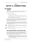
1
Setting Up - Chapter 1
CHAPTER 1
SETTING UP
Unpacking and Inspection
Your Q20 was packed carefully at the factory, and the shipping carton was
designed to protect the unit during shipping. Please retain this container in the
highly unlikely event that you need to return the Q20 for servicing.
The shipping carton should contain the following items:
¥
¥
¥
¥
¥
✪
This instruction manual
Alesis Q20 with the same serial number as shown on shipping carton
AC Power Cable
Alesis warranty card
Quick Reference Guide
It is important to register your purchase; if you have not already filled out your
warranty card and mailed it back to Alesis, please take the time to do so now.
AC Power Hookup
The Q20 includes an internal universal power supply which is compatible with any
line voltage from 90-265 VAC, 50-60 Hz. It also includes a removable IEC power
cable suitable for use in the country shipped to.
Note that the Q20 uses a soft power switch which will turn the unit on when
plugged in. It is good practice to turn your mixer inputs or returns down while
connecting the Q20.
✪
Alesis cannot be responsible for problems caused by using the Q20 or any associated
equipment with improper AC wiring.
Line Conditioners and Protectors
Although the Q20 is designed to tolerate typical voltage variations, in todayÕs
world the voltage coming from the AC line may contain spikes or transients that
can possibly stress your gear and, over time, cause a failure. There are three main
ways to protect against this, listed in ascending order of cost and complexity:
¥
Line spike/surge protectors. Relatively inexpensive, these are designed to
protect against strong surges and spikes, acting somewhat like fuses in that
they need to be replaced if theyÕve been hit by an extremely strong spike.
¥
Line filters. These generally combine spike/surge protection with filters that
remove some line noise (dimmer hash, transients from other appliances, etc.).
¥
Uninterruptible power supply (UPS). This is the most sophisticated option. A
UPS provides power even if the AC power line fails completely. Intended for
computer applications, a UPS allows you to complete an orderly shutdown of a
computer system in the event of a power outage, and the isolation it provides
from the power line minimizes all forms of interferenceÑspikes, noise, etc.
Q20 Reference Manual
7
Chapter 1 - Setting Up
Audio Connections
The connections between the Q20 and your studio are your musicÕs lifeline, so use
only high quality cables. These should be low-capacitance shielded cables with a
stranded (not solid) internal conductor and a low-resistance shield. Although
quality cables cost more, they do make a difference. Route cables to the Q20
correctly by observing the following precautions:
¥
Do not bundle audio cables with AC power cords.
¥
Avoid running audio cables near sources of electromagnetic interference such as
transformers, monitors, computers, etc.
¥
Use balanced cables whenever possible.
¥
Do not place cables where they can be stepped on. Stepping on a cable may not
cause immediate damage, but it can compress the insulation between the center
conductor and shield (degrading performance) or reduce the cableÕs reliability.
¥
Avoid twisting the cable or having it make sharp, right angle turns.
¥
Never unplug a cable by pulling on the wire itself. Always unplug by firmly
grasping the body of the plug and pulling directly outward.
¥
Although Alesis does not endorse any specific product, chemicals such as Tweek
and Cramolin, when applied to electrical connectors, are claimed to improve
the electrical contact between connectors.
Typical Applications
The analog audio inputs and outputs are typically used in one of three ways:
¥
from one or two effect/aux send outputs of a mixer, and out to the effect return
inputs of the mixer; or,
¥
from a line-level instrument (like a guitar or keyboard with either a mono or
stereo output), and out to an amplifier or mixer input; or,
¥
from the stereo buss outputs of a mixer to a mix-down tape machine or
amplifier.
When used with a mono source, the Q20 is placed between the source and the
mixer/amplifier. Although the source may be mono, both the [LEFT] and [RIGHT]
outputs can be connected to the inputs of a mixer/amplifier if stereo processing
effects are desired. Alternatively, you could use the INSERTS on your mixer to
Òpatch inÓ only the left or right channel of the Q20. If using the effect sends of a
mixer, you have the advantage of sending any of the mixerÕs input channels to the
Q20Õs input(s), and have control over the level of each channel being sent.
There are other combinations of input and outputs possible when you begin using the
Alesis optical digital input and output. See the ÒDigital ConnectionsÓ section later
in this Chapter. For more information on interfacing with other digital audio
equipment, see Chapter 7.
8
Q20 Reference Manual
Setting Up - Chapter 1
Interfacing Directly with Instruments
✪
When connecting audio cables and/or turning power on and off, make sure that all
devices in your system are turned off and the volume controls are turned down.
The Q20 has two balanced inputs and two balanced outputs. These provide three
different (analog) audio hookup options:
¥
Mono. Connect a cable to the [L] INPUT of the Q20 from a mono source, and
another cable from the [L] OUTPUT of the Q20 to an amplification system or
mixer input.
¥
Mono In, Stereo Out. While still using a mono input, you could connect two cables
to the [L] and [R] OUTPUTS of the Q20 to a stereo amplification system or two
mixer inputs.
From Instrument or Effects Send
¥
To Amplifier or Mixing Console
Dual Mono or Stereo Source. The Q20 may be used with two different instruments
simultaneously, or with a stereo instrument. The hookup is the same; the
difference is in the routing used within a program. A program may process the
two inputs discretely, using blocks dedicated to a single channel (for example, a
delay for a guitar and a gated reverb for a bass), or process them in stereo (for
example, with the left and right outputs of a keyboard routed through two reverb
blocks). Connect two cables to the [L] and [R] INPUTS of the Q20 from two mono
sources or from the stereo output of the instrument, then connect two other cables
from the [L] and [R] OUTPUTS of the Q20 to a stereo amplification system or two
mixer inputs.
From Instrument or Effects Send
To Amplifier or Mixing Console
Note: In most cases when plugging an instrument directly into the Q20 , youÕll use
Programs which route the "dry" signal at the input(s) directly to the output(s),
where it will be mixed together with the effected signal to achieve the proper
wet/dry mix at the Q20's outputs. If the program doesn't include this routing, you
will only hear the effected signal by itself. Therefore, it may be necessary to edit
such programs to add these "dry" routes when using the Q20 directly with an
instrument. (The Factory Preset programs usually include these routes.)
Q20 Reference Manual
9
Chapter 1 - Setting Up
Interfacing to a Mixing Console
The Q20 handles mono or stereo sends at all system levels. The input circuitry of the
Q20 can easily handle +4 dBu levels (+17.5 dBu peaks), while having enough input
and output gain to interface with the lower -10 dBV signal levels of many recording
systems.
The Q20 may be connected to a mixing console in several ways. Usually, it is
connected to the auxiliary send and return controls of the mixer. Another method of
interfacing is to connect the unit directly to the insert send and return patch points
of the channel that is to be effected. Still another way of interfacing the Q20 to a
mixer or recording console would be in-line across the output of your mixing console.
This last setup would be used only if you needed to effect the entire mix.
Using the Aux Sends
Generally, mixing consoles provide two types of auxiliary sends: pre-fader sends for
creating a cue (headphone) mix, and individual, post-fader effect sends. Typically,
if a mixer has more than two sends per channel (4, 6 or 8, perhaps), the first two
sends are reserved for the cue sends, while the remaining sends are used to feed
effects. If you are using a mixer with more than two sends, connect the Q20 using
post-fader sends.
Using a mixerÕs aux sends poses a distinct advantage: each channel has its own
level control feeding the aux output (and eventually the Q20 input). This allows
you to make a mix of any channels you want to go to the effects by using the
individual channelsÕ aux send levels on the mixer. Most consoles also have aux
master controls, which set the overall level of each aux output.
Coming back from the Q20Õs outputs into the mixer, you have two options:
¥
connecting to dedicated return inputs, or
¥
connecting to channel inputs.
The former is good if your mixer provides dedicated inputs (called returns) for effect
devices like the Q20. If your mixer does not have these, or you have already used
them all, consider connecting the Q20 to channel inputs or unused tape returns. You
may also want to take advantage of better EQ, panning or automation options on
your consoleÕs channel inputs.
10
Q20 Reference Manual
Setting Up - Chapter 1
Setting the Effect/Dry Balance
No matter where you connect the output of the Q20 into the mixer, you are in control
of the balance between the mixerÕs channel inputs (the uneffected signal being
routed to the aux sends and the Mix) and the effect returns coming from the Q20. The
effect returns generally should only contain effected signal, and not have any
uneffected signal mixed with it (since these two signals are blended together at the
mixer).
If the Program you are using has the L/R IN connected to the L/R OUT, you may be
getting some dry, uneffected signal at the return. Generally, this is not desirable
when using the Q20 with a mixer, since the "dry" signal is already being heard
through the original channelÕs fader. Therefore, in a mixer application you will
want to cut the Q20Õs ProgramÕs path which connects the inputs to the outputs. This
can be done in three ways:
✪
¥
Go to the Mix parameters to bring down the direct level
¥
Go to the Routing function of each program and remove the patch cords
connecting the inputs to the outputs
¥
Turn on the Global Direct Signal Mute function. This is the easiest method.
Most Preset Programs route the L/R IN signal to the L/R OUT.When connecting to a
mixerÕs aux sends and returns. the Global Direct Signal Mute should be set to MUTE.
To remove all direct routings of inputs to outputs on all Programs simultaneously:
➀ Press [GLOBAL].
The [GLOBAL] LED will be lit.
➁ Press [< PAGE] once.
This selects Global Page 9. The display will read:
GLOBAL DIRECT SIGNAL: ON
➂ Turn the [VALUE/ENTER] knob to the right until the display reads ÒON.Ó
The next Program recalled which has the inputs routed to the outputs will not
display the patch cords for these connections nor will you hear any direct
uneffected signal at the outputs.
Q20 Reference Manual
11
Chapter 1 - Setting Up
Mono In - Stereo Out. If you only want to feed the Q20 a mono input, but wish to
connect both of its outputs back to the mixer, you will need three audio cables.
Connect a cable from an effect send to the [L] INPUT of the Q20, another cable from
the [L] OUTPUT of the Q20 to an effect return or other mixer input, and another
cable from the [R] OUTPUT of the Q20 to an adjacent mixer input.
Left Input
Left and
Right
Outputs
Aux Send 3
Stereo Aux Returns
Stereo In - Stereo Out. This connection is similar to the one described above.
However, by utilizing two sends from the mixer, we add one more cord and can now
send a stereo signal to the Q20Õs inputs. Example, if you connected effect sends 3 and 4
to the [L] and [R] INPUTS, and had a stereo instrument (such as a keyboard)
connected to two channel inputs of the mixer (either one panned hard left and hard
right), you would send the left channel to send 3 and the right channel to send 4.
Alternatively, you could have two discrete effect sends between the Left and Right
channel, and process each separately within the Q20. For example, the Left
channel (from send 3) could be a chorus, and the Right (from send 4) could be a reverb.
This is similar to Dual Mono, described earlier.
Left Input
Right Input
Left and
Right
Outputs
Aux Send 3
12
Aux Send 4
Stereo Aux Returns
Q20 Reference Manual
Setting Up - Chapter 1
Using Inserts
By using individual channel inserts, you can dedicate the Q20 to a specific channel
(or pair of channels) on the mixer. The Insert connections on the back of the mixer
provide a way of ÒinsertingÓ external processing equipment into the signal path.
The insert occurs after the input amplifier, and before the main fader; essentially it
is the same as connecting the source (instrument or microphone) into the Q20 before
the mixerÕs channel input. However, some mixing consoleÕs inserts come after the EQ
section, and may therefore be different from the original signal.
Usually, insert connections require a special, stereo-splitting Y-cord to be connected
(one stereo plug provides both send and return while two mono plugs connect
separately to an input and output). These are known as TRS connectors (tip-ringsleeve). The tip of the stereo plug typically carries the send or output of the insert
jack, while the ring carries back the return. The sleeve represents a common ground
for both signals. Check the manual of your mixer because some are wired differently
(for example, having two separate jacks for send and receive).
Mono. This involves connecting a 1/4" TRS (tip-ring-sleeve) to the Insert jack of a
single channel on a mixing console. The other end of the cable (which splits into
two, 1/4" mono connectors) are connected to the [L] INPUT and [L] OUTPUT,
respectively. If you do not hear any audio after making these connections, swap the
input and output cables at the Q20, as these may be wired backwards. If the cable is
color-coded, usually the red jack represents the send (which connects to the Q20Õs
INPUT) and black is the return (which connects to the OUTPUT).
Left Output
Left Input
Channel
Insert
Q20 Reference Manual
13
Chapter 1 - Setting Up
Stereo. In the case where a stereo instrument, such as a keyboard or sampler, is
connected to two separate channels of a mixing console, you will need two 1/4" TRS
cables, one for each channel. The connection is made in a similar fashion as
described above.
Right
Input
Right
Output
Left
Output
Left
Input
Right
Insert
Left
Insert
Using Main Outputs
When you want to effect everything on the mixer, you can connect the Q20 between
the mixerÕs outputs and the amplifierÕs or tape machineÕs inputs. This is done by
using two cables to connect the Left and Right Main Outputs of the mixing console to
the [L] and [R] INPUTs of the Q20. The [L] and [R] OUTPUTs of the Q20 are then
connected to a stereo amplifier, or two input channels of another mixing console (for
sub-mixing applications).
Left
Output
Left
Input
Right
Input
Left
Master
Out
Right
Master
Out
Right
Output
Power
Amp
Left
Input
Power
Amp
Right
Input
Out to Speakers
14
Q20 Reference Manual
Setting Up - Chapter 1
When to use Balanced Connectors
There are three options for connecting analog audio to the Q20: 1/4Ó unbalanced,
1/4Ó balanced (TRS) and XLR balanced. If your source and destination use balanced
connectors, you should try to stay balanced throughout the chain. Balanced cables
have a higher signal level and have the ability to cancel out hum and noise, which
can make your mixes quieter. XLR connectors have the added bonus of locking into
place, a good idea if you need to move your effects rack from place to place.
Keeping this in mind, your order of preference when connecting the Q20 to a mixer
should be to use the XLR connectors first, then to use balanced 1/4Ó cables, then
unbalanced 1/4Ó cables if your mixer doesnÕt have balanced sends and receives.
Avoiding Ground Loops
In todayÕs complex studio there are many opportunities for ground loop problems to
occur. These show up as hums, buzzes or sometimes radio reception, and can occur if a
piece of equipment ÒseesÓ two or more different paths to ground. While there are
methods to virtually eliminate ground loops and stray radio frequency interference,
most of the professional methods are expensive and involve installing a separate
power source just for the sound system. Here are some easy helpful hints that a
professional studio installer might use to zap those stray hums and buzzes.
➀ KEEP ALL ELECTRONICS OF THE SOUND SYSTEM ON THE SAME AC
ELECTRICAL CIRCUIT. Most stray hums and buzzes happen as a result of
different parts of the sound system being plugged into outlets of different AC
circuits. If any noise generating devices such as air conditioners, refrigerators,
neon lights, etc., are already plugged into one of these circuits, you then have a
perfect condition for stray buzzes. Since most electronic devices of a sound
system donÕt require a lot of current (except power amplifiers), itÕs usually safe
to run a multi-outlet box (or two) from a SINGLE wall outlet, and plug in all of
the components of your system there.
➁ KEEP AUDIO WIRING AS FAR AWAY FROM AC WIRING AS POSSIBLE.
Many hums come from audio cabling being too near AC wiring. If a hum occurs,
try moving the audio wiring around to see if the hum ceases or diminishes. If
itÕs not possible to separate the audio and AC wiring in some instances, make
sure that the audio wires donÕt run parallel to any AC wire (they should only
cross at right angles, if possible).
➂ TO ELIMINATE HUM IF THE ABOVE HAS FAILED:
A) Disconnect the power from all outboard devices and tape machines except
for the mixer and control room monitor power amp.
B ) Plug in each tape machine and outboard effects device one at a time. If
possible, flip the polarity of the plug of each device (turn it around in the
socket) until the quietest position is found.
C) Make sure that all of the audio cables are in good working order. Cables
with a detached ground wire will cause a very loud hum!!
D) Keep all cables as short as possible, especially in unbalanced circuits.
If the basic experiments donÕt uncover the source of the problem, consult your dealer
or technician trained in proper studio grounding techniques. In some cases, a Òstar
groundingÓ scheme must be used, with the mixer at the center of the star providing
the shield ground on telescoping shields, which do NOT connect to the chassis
ground of other equipment in the system.
Q20 Reference Manual
15
Chapter 1 - Setting Up
MIDI
MIDI is an internationally-accepted protocol that allows music-related data to be
conveyed from one device to another. The MIDI connections on the Q20 provide five
different functions:
¥
To recall programs using MIDI program change messages
¥
To control various parameters inside the Q20 in realtime via MIDI controllers
(example: A keyboardÕs mod wheel, or pedals, etc.)
¥
To convert MIDI Clock messages into delay settings on Tap Tempo Delay Blocks
¥
To send and receive SysEx (System Exclusive) dumps of individual programs or
the entire bank of programs for storage and retrieval purposes
¥
To pass-on MIDI information thru the Q20 to another MIDI device.
To connect the Q20Õs MIDI ports to another MIDI device:
➀ Connect a MIDI cable from the Q20Õs MIDI [THRU/OUT] connector to the MIDI
IN connector of the other MIDI device.
➁ Connect another MIDI cable from the Q20Õs MIDI [IN] connector to the other
MIDI deviceÕs MIDI OUT connector.
For more information about MIDI, refer to Chapter 6.
Digital Connections
Digital connections provide better fidelity than the analog inputs and outputs
because you avoid converting the audio from digital to analog (say from a digital
mixer), then to digital (Q20 input), then analog (Q20 output), then digital again
(back into the mixer).
The Q20 provides two formats for direct digital connections: ADAT Optical and
S/PDIF. The Alesis Optical interface provides two EIAJ fiber optic connectors for
[DIG IN] and [DIG OUT]. These connectors use a proprietary Alesis multichannel
format first introduced with the ADAT Multitrack Recorder. The Q20 can send
and/or receive digital audio directly to/from an ADAT (or other devices which use
the same optical interface). The S/PDIF inputs and outputs are provided on coaxial
(phono) jacks and conform to the consumer digital interface format (Sony/Philips
Digital Interface Format).
The proprietary Alesis Optical format carries up to 8 audio channels on a single
fiber optic cable. Since the Q20 has two channels (left and right), you may choose
two of the incoming 8 channels for the Q20 to process or output.
ADAT Optical fiber optic cables of various lengths are available from your Alesis
dealer. The shorter the cable, the better. The OC cable is 5 meters long (16'4") and
is the maximum length recommended. For S/PDIF connection, you should use good
quality video-type phono cables.
16
Q20 Reference Manual
Setting Up - Chapter 1
Footswitches
On the rear panel you will find two footswitch jacks labeled [ADVANCE] and
[BYPASS]. Any momentary single-pole/single-throw footswitch, normally open or
normally closed, will work for the two footswitch functions. These should be
plugged in prior to power-up so that the Q20 can configure itself for the type of
footswitch being used.
Advance
The [ADVANCE] jack lets you scroll through the Programs in memory by advancing
to the next higher numbered Program each time the connected footswitch is pressed.
The Q20 will Òwrap-aroundÓ whenever it reaches the end of available Programs
and the Advance footswitch is pressed again. You can set a range of Programs to be
used, thereby cutting off other Programs from being recalled in this manner. For
example, if you set the range to be User 0-10 through User 0-24, only Programs
within this range will be recalled using the Advance footswitch. If Program 0-24 is
selected and the footswitch is pressed again, Program 0-10 is recalled.
To adjust the Advance FootswitchÕs set of Programs:
➀ Press [GLOBAL].
The [GLOBAL] LED will light.
➁ Press [PAGE >] once.
This selects page 2, and the display will read:
FOOTSWITCH: Preset00 TO User1-99
➂ Turn the [VALUE/ENTER] knob to adjust the Program number to begin the range
(Preset 00 ÑÊ99, User 0-00 Ñ 1-99).
➃ Press [PAGE >] once and use the [VALUE/ENTER] knob to adjust the Program
number to end the range (Preset 00 ÑÊ99, User 0-00 Ñ 1-99).
Bypass
The Bypass footswitch jack lets you turn the Bypass function on and off from a
connected footswitch. When pressed, the [BYPASS] LED will light, indicating that
Bypass mode is enabled. When pressed again, the [BYPASS] LED will turn off.
For more information about Bypass mode, see Chapters 2 and 5.
Q20 Reference Manual
17
Chapter 1 - Setting Up
Tap Tempo
Either footswitch jack can be used to provide a tap tempo source for setting delay
time, provided the selected Program uses one of the two available tap tempo delay
types. This requires that you have defined an Effect Block as one of the two Tap
Tempo delay types, and that the desired footswitch jack has been selected for
controlling tap tempo. To select a footswitch jack for use with a Tap Tempo Delay:
➀ Press [GLOBAL].
The [GLOBAL] LED will light.
➁ Press [< PAGE] twice to select Global Page 8.
The display will read:
TAP TEMPO FOOTSWITCH: NONE
➂ Turn the [VALUE/ENTER] knob to select either the ADVANCE or BYPASS
footswitch jack, depending on which one you wish to use to control tap tempo.
Note that some programs can override these footswitch settings by re-assigning
pedals as Local Generator Sources in the Modulation pages. See Chapter 6 for more
information.
18
Q20 Reference Manual