1
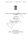
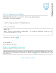
DC265 / DC365
INSTALLATION & OWNERS' MANUAL
In-Ceiling / In-Wall Loudspeakers
DC265 / DC365 INSTALLATION
Mounting Considerations
Dual architectural speakers are designed to work within nearly all interior decorating
schemes where in-wall or flush mounting is feasible. Wall mounted and ceiling
mounted speakers should be installed away from corners or intersecting walls, and
directly adjacent to the listening area. This placement gives the best audio imaging.
Position your speakers symmetrically for best results.
Sound Coverage and Speaker Placement
Your design approach should take in to consideration the intended use of your
speakers. Sound coverage and audio imaging should be viewed as seperate goals.
Speaker Coverage: This installation may be desired if the speakers are intended to
be used as an intercom based music system. Typical ceiling speakers should not be
spaced greater then two times (x2) the ceiling height. Measure floor to ceiling and
multiply by two. An example using this rule and the table below: If you had an 8 foot
ceiling, a pair of speakers would be spaced 16 feet apart, which would result in a
coverage area of 500 square feet.
Ceiling Speaker Coverage in Square Feet
# Speakers
1
2
3
4
5
6
8’
250
500
750
1,000
1,250
1,500
9’
325
650
975
1,300
1,625
1,950
Ceiling Height
10’
400
800
1,200
1,600
2,000
2,400
11’
485
970
1,450
1,930
2,410
2,890
12’
575
1,150
2,300
2,875
3,450
4,025
Please check your intercom owners' manual to determine the correct impedance loading
for multiple speakers.
2
DC265 / DC365 COVERAGE & SPEAKER PLACEMENT
Sound Coverage and Speaker Placement
Audio Imaging: Ceiling or wall speakers can be used as pairs for stereo or used in
multiples for 5.1 to 7.1 multi-channel applications. Ideally you should place the stereo
or front left and right speakers as directionally balanced as possible to the primary
listening area.
A common rule is to position the front speakers so that the distance between the
listening position and the wall is 1.5 times the distance between the two speakers, but
the speakers can be further apart if you desire a wider sound stage. In a typical audio/
video multi-channel setup, the listening position is directly facing the video source (TV
or Monitor) and the center channel is on a direct plane with the listener. If the listener
is positioned 15 feet away from that video source, then the optimal distance between
the left and right speakers would be 22.5 feet apart (15'x1.5).
Listener
Equidistant Example
The speaker imaging decreases rapidly the further the listener is from the speakers,
so an equidistant speaker arangment for multi-channel installation is desired for the
best results. Try to equalize the speakers distance so the listener is basically in the
middle of the sound stage.
3
DC265 / DC365 COVERAGE & SPEAKER PLACEMENT
Sound Coverage and Speaker Placement
When possible, try to reduce the distance of your speaker from the audio source to achieve
the best audio results. The optimum wire run should be no longer than 30 feet for the most
favorable results. If you must run wire longer than 30 feet, we recommend using larger
wire of 12 or 14 gauge.
Among the factors to consider in the planning of your speaker placement is that the front
of the speakers should be free from such obstructions as furniture or built in architecural
features. High and midrange frequencies will be absorbed by fabric, carpet, curtains and
soft furnisings. Walls and hard floors will reflect sound waves.
Regardless of the speaker model (ceiling or wall), the speakers should not be installed
closer then 3' from adjacent or intersecting walls.
IMPORTANT:
The DC265 is not magnetically shielded. Avoid mounting speakers closer than 20” from
a video monitor or TV screen. After installation, if any video or TV screen distortion is
detected, the video monitor or TV must be moved beyond the effect of the magnet motor.
The magnets will distort and discolor the screen and could cause permanent damage to the
picture tube.
Multiple pairs of speakers placed in strategic locations within your coverage area can be a
fundamental solution when designing a system that requires large coverage.
Keep in mind that wire must be run to the location of the speakers. Walls, studs, ducts
and joists in your home may be difficult to get around when wiring your speakers, so
understanding your home's construction and properly planning your design is important.
An example is a home constructed of block with limited wall depth. This would present a
problem for inwall installation and wire management.
4
DC265 / DC365 INSTALLATION
Installation Tips
Caution: Do not attempt to connect the speakers to any source, amplifier or receiver that is
turned on. Be sure the receiver is off prior to connecting the speakers.
Adhere to all electrical and building code requirements for your area.
The minimum mounting depth of 4" measured from the face of the wall or ceiling is needed
for proper clearance. The speakers can be placed beside studs or other wall interior items
but avoid near proximity to pipes, machinery and high amperage wiring.
The DC265 is designed to use the wall cavity as the enclosure. It is not necessary to install
an enclosure unless required to do so by local electrical or fire regulations.
The mounting tab brackets incorporated into the speakers can accommodate sheet rock or
wall board thicknesses of 1/2” to 1-3/8”. Spacers or longer screws can be used on thinner
or thicker surfaces.
Push Lock Speaker Terminals
Built-in “easy turn” wall mounting tabs
Adding insulation such as 3" to 4” insulation or damping material behind the speaker
generally improves the sound quality.
5
DC265 / DC365 INSTALLATION
Installation Tips
Parallel or series wiring is not recommended for these speakers. The speakers should
only be connected to receivers with 4-8 ohm amplifier loading. Avoid parallel or series
wiring your Dual speakers with any other speaker type or brand.
Always connect speaker wires using the correct polarity. Speaker wires are marked for
polarity consistency so that you can determine the positive and negative identity of the
individual wires within the molded pair insulation. Polarity is shown by either a color stripe
on the insulation, by ridges molded into one side of the insulation, the color of the insulation
case around the wire, or by the color type or colors of the wires/wire itself (copper or
silver).
Important: In order to maintain correct polarity, always connect speaker wire using the
positive (+) terminal on the receiver to the positive (+) wire, and the negative (-) terminal on
the receiver to the negative (-) wire.
6
DC265 / DC365 INSTALLATION
Installation Guide
When ceiling mounting your speakers, attempt to make the locations as symmetrical as
possible.
When wall mounting, carefully measure the distance from the floor to the speaker center
so both speakers are the same distance from the floor. You may use the template that is
included with your Dual speakers to determine the correct cut-out dimensions.
Cut the hole or opening using a sheet rock saw, keyhole saw or other suitable tool. Place
the speaker in the opening to verify a correct flush fit.
Remove the speaker grille at this point of the installation to gain access to the screws
which turn the mounting tabs that will secure the speaker to the mounting surface. The
screw heads that lock the tabs can be identified by turning the speaker over and pushing
on the tab. The corresponding screw head will protrude identifying which screws you will
need to turn once the speaker is connected, and in the proper position within the wall or
ceiling.
Run speaker wires from the amplifier to the speakers. Allow an extra 2' of wire at the
speaker cutout location to make installation easier. Strip and twist about 1/2” of insulation
off the speaker wires. The speaker wire runs should be hidden as well as possible
within the wall or ceiling and should not come in contact the speaker basket, be wrapped
around the crossover network or hang loosely near a stud as vibration may cause poor
sound quality.
Insert the speaker into the opening cut in the wall or ceiling, slide the whole speaker
into the wall cavity and center the speaker in the opening. Once the speaker wires are
attached and all wire management is complete and the speaker is in the flush position,
turn the screw heads associated with the tabs clock-wise to tighten the tabs against the
wall or ceilings interior surface.
7
DC265 / DC365 INSTALLATION
Installation Guide
Test your system to insure all connections are correct and the speakers are active.
These speakers are designed with adjustable tweeters. The tweeters can be rotated
or pivoted if desired. The angle of the tweeters can be adjusted diametrically and to a
maximum of approximately 20 degrees off axis.
Do not force the pivots beyond the limits of the built in stop positions. The maximum
position or stop can be felt during the adjustment. If the tweeter stops moving in that
direction, then it is safe to conclude that you are at the maximum adjustment. Please do
not force further movement in that direction!
Replace the white (paintable) grill into the speaker baffle. If a color other than white is
desired, the baffle and grille can be painted to match any interior. Most indoor paint
types are suitable. Primer can be used when darker colors are required. Please avoid
painting the inner black baffle or drivers as this will affect the sound quality and reduce the
performance of the tweeter dramatically. When using spray method of painting, mask the
interior baffle to protect the drivers from overspray.
8
DC265 / DC365 TROUBLESHOOTING
Problems?
Troubleshooting
If you hear obvious distortion from the speakers,
immediately lower the volume level of your receiver.
Those sounds often indicate that either the receiver or
the speaker is being overdriven, and damage can result
in playing your source material (music-CDs-DVD-MP3)
at high volume levels for prolonged periods of time. You
should also avoid turning the bass or treble controls fully
up and using your "Loudness button" when the volume
level is at or above normal listening levels.
Loudness Button
The Loudness button on most receivers is designed
to add depth when your system is being used for
background music or being played at very low volume.
Unnatural Sounds
Distorted or unnatural sound can indicate poor
connections, defective electronics, damaged source
material or speaker failure. If only one of your speakers
has poor sound quality, check the speaker wire and
audio connections.
For Your Records
You must have proof of purchase to receive warranty
service.
Please keep your original sales receipt and be prepared
to provide this receipt in the event you require service,
as your original receipt is considered the best proof of
purchase and indicates the date you purchased your
Dual product.
Dual Model _____________________________________
Dealer Name____________________________________
Dealer Phone____________________________________
Purchase Date____________________
Note: You may want to keep your original sales receipt or a
photo copy with this installation/owner’s manual.
9
DC265 / DC365 WARRANTY
Limited Two-Year Warranty
This warranty gives you specific legal rights. You may
also have other rights which vary from state to state.
Dual Electronics Corp. warrants this product to the
original purchaser to be free from defects in material
and workmanship for a period of two years from the
date of the original purchase.
Dual Electronics Corp. agrees, at our option, during
the warranty period, to repair any defect in material
or workmanship or to furnish an equal new, renewed
or comparable product (whichever is deemed
necessary) in exchange without charges, subject to
verification of the defect or malfunction and proof
of the date of purchase. Subsequent replacement
products are warranted for the balance of the original
warranty period.
What to do?
1. Before you call for service, check the
troubleshooting guide in your owner’s manual.
A slight adjustment of any custom controls or
connections discussed in your instruction booklet may
save you a service call.
2. If you require service during the warranty period,
you must carefully pack the product (preferably in the
original package) and ship it by prepaid transportation
with a copy of the original receipt from the retailer to
an authorized service center.
3. Please describe your problem in writing and
include your name, a return UPS shipping address
(P.O. Box not acceptable), and a daytime phone
number with your shipment.
Who is covered? This warranty is extended to the
original retail purchaser for products purchased and
used in the U.S.A.
4. For more information and for the location of the
nearest authorized service center please contact us
by one of the following methods:
What is covered? This warranty covers all defects
in material and workmanship in this product. The
following are not covered: installation/removal costs,
damage resulting from accident, misuse, abuse,
neglect, product modification, improper installation,
incorrect line voltage, unauthorized repair or failure
to follow instructions supplied with the product, or
damage occurring during return shipment of the
product.
Call us toll-free at 1-866-382-5476
E-mail us at [email protected]
10
Exclusion of Certain Damages: This warranty is
exclusive and in lieu of any and all other warranties,
expressed or implied, including without limitation
the implied warranties of merchantability and fitness
for a particular purpose and any obligation, liability,
right, claim or remedy in contract or tort, whether or
not arising from the company’s negligence, actual or
imputed. No person or representative is authorized
to assume for the company any other liability in
connection with the sale of this product. In no event
shall the company be liable for indirect, incidental or
consequential damages.
DC265 / DC365 SPECIFICATIONS
DC265
DC365
•
•
•
•
•
•
•
•
•
•
•
•
•
•
•
•
•
•
•
•
•
•
•
•
•
•
•
Black polypropylene woofer cone
Silk dome tweeter
Rotating directional tweeter
Tweeter protection circuitry
Built-in crossover
Silver plated speaker binding posts
Paintable speaker grille and frame
150 Watts Maximum Power Handling
100 Watts RMS Power Handling
89 dB SPL +/-3dB
50 Hz to 20,000 Hz
8 ohm Nominal Impedance
Black carbon fiber cone
Santoprene surround
Rear speaker enclosure
Titanium dome tweeter
Rotating directional tweeter
Tweeter protection circuitry
Adjustable tweeter Level control
Built-in crossover
Gold plated speaker binding posts
Paintable speaker grille and frame
180 Watts Maximum Power Handling
120 Watts RMS Power Handling
92 dB SPL +/-3dB
45 Hz to 20,000 Hz
8 ohm Nominal Impedance
Dual Electronics Corp.
21318 64th Ave. South
Kent, WA 98032
Toll Free: 1-866-382-5476
www.dualav.com
©2006 Dual Electronics Corp.
NSA0306-V01