1
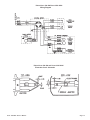
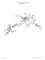
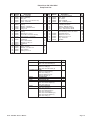
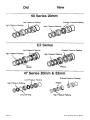
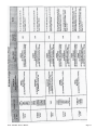
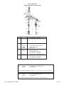
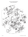
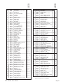
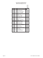
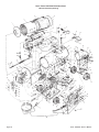
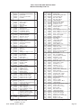
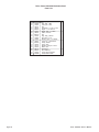
Pressu re Wash ers
VERSA 100
VERSA 100C
PN 09043X
PN 09043D
VERSA 200C
PN 09041E
PN 09041C (S.S.)
Operators Manual and
Replacement Parts Book
Rev1 11-07
Delco Pressure Washers - LIT-VER1-DEL
LIMITED WARRANTY
At DELCO® CLEANING SYSTEMS, we distribute top quality industrial / commercial / personal pressure
washers that are designed for heavy-duty use, maximum reliability, durability, and long life. Our pressure
washers are built for all duty applications and steady use due to higher quality levels.
The manufacturer of this product agrees to repair or replace designated parts that prove defective within the
warranty period of one (1) year listed in the chart. Specific limitations/extensions and exclusions apply,
and are listed in the chart on page 3. This warranty covers defects in material and workmanship and not parts
failure due to normal wear; abuse; accidental damage; negligence; improper use, maintenance,
and storage. To make a claim under the terms of the warranty, all parts said to be defective must be available
or returned (if requested) to DELCO® CLEANING SYSTEMS designated Warranty Service Center for
warranty inspection. The judgments and decisions of the Warranty Service Center concerning the validity of
warranty claims are final.
These warranties pass through to the end user. As a factory authorized and trained Warranty Service Center
the factory will honor the terms of all component warranties and satisfy claims of the appropriate warranty
provisions.
Normal wear items include, but are not limited to, Valves and Seals, which are not covered by this warranty.
This Warranty replaces all other warranties, express or implied, including without limitation any warranties of
merchantability or fitness for a particular purpose and all such warranties are hereby disclaimed and excluded
by the manufacturer. The Manufacturer’s warranty obligation is limited to repair and replacement of defective
products as provided herein and the Manufacturer shall not be liable for any further loss, damages, or
expenses – including damages from shipping, accident, abuse, acts of God, misuse, or neglect. Neither is
damage from repairs using parts not purchased from the manufacturer or alterations performed by non-factory
authorized personnel. Failure to install and operate equipment according to the guidelines put forth in the
instruction manual shall void warranty.
This warranty does not cover the following: damage resulting from shipping (claims must be filed with freighter),
accident, abuse, act of God, misuse, or neglect. Neither is damage from repairs or alterations performed by
non-factory authorized personnel or failure to install and operate equipment according to the guidelines put
forth in the instruction manual.
The manufacturer will not be liable to any persons for consequential damage, for personal injury, or for
commercial loss.
LIMITED WARRANTY (cont)
Parts / Components
High Pressure Pumps
Warranty Period and Details
Five (5) year limited manufactuer warranty on pump
workmanship and defects in material.
Lifetime on forged brass manifold.
Warranty does not apply to failures on other pump parts due
to:
• Freight damage
• Freeze damage
• Damage caused by parts or accessories not obtained
from / or approved by Delco
• Normal wear of moving parts or components affected
by moving parts.
Engines
Covered by engine manufacturer warranty. See engine manual.
Electric Motors (if applicable)
One (1) year from date of first start up.
Burners (hot water machines)
One (1) year from date of first start up.
Hot Water Burner Coil
(hot water machines)
Five (5) years from date of first start up.
Warranty only covers workmanship or defects of material.
Warranty does not apply to:
• Freeze Damage
• Over Pressure burst damage caused by improper
maintenance of safety devices.
Frame
One (1) year from date of first start up.
Accessories
Ninety (90) days. Includes tips, guns, wands,
injectors, unloaders, hose reel, brushes, foamers,
Table of Contents
Operator Safety Instructions . . . . . . . . . . . . . . . . . . . . . . . . . . . . . . . . . . . . . . . . . . . . . . . . . . . . 5 - 6
Introduction and Machine Specifications . . . . . . . . . . . . . . . . . . . . . . . . . . . . . . . . . . . . . . . . . . . . . 7
Machine Operation Instructions. . . . . . . . . . . . . . . . . . . . . . . . . . . . . . . . . . . . . . . . . . . . . . . . . . . . 8
Maintenance . . . . . . . . . . . . . . . . . . . . . . . . . . . . . . . . . . . . . . . . . . . . . . . . . . . . . . . . . . . . . . . . . 9
Freeze-Up Prevention . . . . . . . . . . . . . . . . . . . . . . . . . . . . . . . . . . . . . . . . . . . . . . . . . . . . . . . . . 10
How to Correct Problems in the Machine . . . . . . . . . . . . . . . . . . . . . . . . . . . . . . . . . . . . . . . . 11 - 12
Wiring Diagram -115V . . . . . . . . . . . . . . . . . . . . . . . . . . . . . . . . . . . . . . . . . . . . . . . . . . . . . . . . . 13
Electrode Check Schematic . . . . . . . . . . . . . . . . . . . . . . . . . . . . . . . . . . . . . . . . . . . . . . . . . . . . . 13
Pump Drawing . . . . . . . . . . . . . . . . . . . . . . . . . . . . . . . . . . . . . . . . . . . . . . . . . . . . . . . . . . . . . . . 14
Parts List . . . . . . . . . . . . . . . . . . . . . . . . . . . . . . . . . . . . . . . . . . . . . . . . . . . . . . . . . . . . . . . . . . . 15
Packings . . . . . . . . . . . . . . . . . . . . . . . . . . . . . . . . . . . . . . . . . . . . . . . . . . . . . . . . . . . . . . . . . . . 16
Kit Interchange/ Cross Reference . . . . . . . . . . . . . . . . . . . . . . . . . . . . . . . . . . . . . . . . . . . . . . . . . 17
Unloader Valve Drawing and Parts List . . . . . . . . . . . . . . . . . . . . . . . . . . . . . . . . . . . . . . . . . . . . 18
59420A Unloader Valve Drawing and Parts List . . . . . . . . . . . . . . . . . . . . . . . . . . . . . . . . . . . . . . 19
Assembly Drawing - Painted Versa 100 and 100C. . . . . . . . . . . . . . . . . . . . . . . . . . . . . . . . . . . . 20
Parts List . . . . . . . . . . . . . . . . . . . . . . . . . . . . . . . . . . . . . . . . . . . . . . . . . . . . . . . . . . . . . . . . 21 - 22
Burner Drawing and Parts List . . . . . . . . . . . . . . . . . . . . . . . . . . . . . . . . . . . . . . . . . . . . . . . . . . . 23
Assembly Drawing - Stainless Steel Versa 100C . . . . . . . . . . . . . . . . . . . . . . . . . . . . . . . . . . . . . 24
Parts List . . . . . . . . . . . . . . . . . . . . . . . . . . . . . . . . . . . . . . . . . . . . . . . . . . . . . . . . . . . . . . . . 25 - 26
Fuel Filter Components . . . . . . . . . . . . . . . . . . . . . . . . . . . . . . . . . . . . . . . . . . . . . . . . . . . . . . . . 27
Page 4
Versa 100/100C Owner's Manual
OPERATOR SAFETY INSTRUCTIONS
WARNING
AVERTISSEMENT
ADVERTENCIA
DANGER means:
Severe bodily injury or death can occur to you or other personnel if the
DANGER statements found on your machine or in your Owner's Manual are
ignored or are not adhered to. Read and observe all DANGER statements
found in your Owner's Manual and on your machine.
WARNING means:
Injury can occur to you and to other personnel if the WARNING statements
found on your machine or in your Owner's Manual are ignored or are not
adhered to. Read and observe all WARNING statements found in your
Owner's Manual and on your machine.
CAUTION means:
Damage can occur to the machine or to other5 property if the CAUTION
statements found on your machine or in your Owner's Manual are ignored or
are not adhered to. Read and observe all CAUTION statements found in
your Owner's Manual and on your machine.
WARNING:
ADVERTISSEMENT:
WARNING:
ADVERTISSEMENT:
WARNING:
Do not use gasoline, crankcase drainings, or oil containing gasoline or solvents.
Ne pas utiliser d'essence, de produits de vidange ni d'huile cintenant de l'essence ou des
solvants.
This machine is not to be connected to a type B gas vent.
Ne pas raccorder cet appariel à un tuyau d'évacuation de gas du type B.
Risk of injection or severe injury. Keep clear of nozzle. Do not direct discharge stream at
persons. This equipment is to be used only by trained persons.
ADVERTISSEMENT:
Risque d'injection et de blessures graves. Se tenir à lécart du jet. Ne pas diriger le jet de sortie
vers d'autres personnes. Confier l'utilisation de ce matérial à un opérateur qualifié.
WARNING:
If you smell gas, shut off the gas supply to the appliance, extinguish any open flame, and test all
joints with a soap solution. If the odor persists, call your gas supplier immediately.
ADVERTISSEMENT:
Si une odeur de gas est dècelèe, couper l'alimentation en gas de l'appareil, èteindre toutes les
flammes et vérifier tous les raccords à làide d'une solution savonneuse. Si l'odeur persiste,
avertir immédiatement le fournisseur de gas.
DANGER:
Failure to read the Owner's Manual prior to using this machine could result in injury to you or to
other personnel; damage to the machine or to other property could occur as well. You must have
training in the operation of this machine before using it. If you or your operator(s) cannot read
English, have this manual explained fully before attempting to operate this pressure washer.
DANGER:
Machines can cause an explosion when operated near flammable materials and vapors. Do not
use this machine with or near fuels, grain dust, solvents, thinners, or other flammable materials.
DANGER:
This machine emits carbon monoxide. Asphyxiation could occur if the unit is used in an area with
poor or inadequate ventilation. Operate unit in a well-ventilated area. Do not connect the exhaust
stack directly to a flue pipe. This may cause sooting of the combustion chamber. If you must vent
to the outside use a hood type vent or an exhaust fan. Install flue pipes in accordance with all local
codes.
DANGER:
Operating a machine that is not completely or fully assembled could result in injury or property
damage. Do not operate this machine until it is completely assembled. Inspect hoses, fittings, and
heat exchanger for leaks or fatigue before each use.
Versa 100/100C Owner's Manual
Page 5
DANGER:
Filling a machine with fuel in an explosive or poorly-ventilated area can cause an explosion. Only
fill the fuel tank in an open area. Do not fill the tank near open flames or while the unit is running.
Do not smoke while filling the tank. Do not over-fill the tank. Wipe up any spills. Tighten the cap
on the tank when finished. Use kerosene, or #1 or #2 diesel as a fuel only. Do not use K-1
kerosene.
DANGER:
Tampering with the machine's factory preset unloader valve setting and/or the pressure relief valve
setting could result in a machine explosion. Do not attempt to change the settings. Discontinue
use if a malfunction occurs and contact your local authorized Delco distributor.
DANGER:
Operating a pressure washer with a malfunctioning burner or burner controls could result in a
machine explosion. Inspect burner and burner control operation before each use. If you suspect a
problem with the burner, discontinue use immediately and contact your local authorized Delco
distributor for assistance.
DANGER:
Failure to properly maintain the heat exchange coil can result in a steam explosion. Scale or lime
build-up will act as an insulation and decrease the efficiency of the heat exchanger coil and will also
cause hot spots. This can result in a weakening of the tubing which in turn may cause a rupture.
Reference the Operator Safety Manual, part no. 78336A for more information on maintenance of the heat exchange coil.
DANGER:
Operating a machine with a ground fault circuit interrupter (GFCI) that has been tampered with, or
one that repeatedly trips, could result in an electrocution. Do not remove, disable, or tamper with
the GFCI. If the ground fault circuit interrupter repeatedly trips, discontinue use of the machine.
Contact your local authorized Delco distributor for assistance with the GFCI.
DANGER:
Electrocution could occur if the machine is used on a power circuit that repeatedly trips or is
undersized. Have a licensed electrician check the fuse, circuit breaker or power supply, and/or
contact your local authorized Delco distributor for assistance.
DANGER:
Electrocution could occur if maintenance and repairs are performed on a unit that is not properly
disconnected from the power source. Disconnect the power supply before attempting any maintenance or service.
DANGER:
Use of this machine with a damaged power cord could result in an electrical shock. Do not use the
machine if the power cord is damaged. Do not use the electrical cord to move the machine.
WARNING:
Water under high pressure can cause severe injury. Keep all persons away from the machine and
the spray area. Always point the wand toward the object being cleaned.
WARNING:
Injury to the operator or bystanders could occur if the machine is operated without all of the guards
being in place on the unit. When operating the machine, all guards must be in place.
WARNING:
Operating a pressure washer under high pressure without a securely fastened hose, gun and spray
nozzle(s) could result in bodily injury or property damage. Make sure the spray nozzle, gun and hose
are securely fastened before operating the machine. Do not remove the nozzle or disconnect the high
pressure hose while the system is pressurized and/or running.
WARNING:
Machines have moving parts and hot areas that can cause injury. Keep hands, feet, and loose
clothing away from the pressure washer while it is running. After use, allow an adequate amount of
cool-down time before attempting to perform any maintenance or service to this unit.
WARNING:
Failure to wear safety goggles and protective clothing when operating a pressure washer reduces
operator safety. Always wear safety goggles and protective clothing when the machine is running
or when operating machine.
WARNING:
Operating this pressure washer without the appropriate decals could result in operator injury or
damage. Make sure all labels and instructional information are fastened to the machine. Get new
labels and decals from your Delco distributor.
CAUTION:
Maintenance and repairs performed by unauthorized personnel could result in damage or injury.
Servicing of this unit must always be referred to an authorized Delco distributor.
Page 6
Versa 100/100C Owner's Manual
CAUTION:
Maintenance and repairs performed by unauthorized personnel will void your warranty. Servicing of
this unit must always be referred to an authorized Delco distributor.
CAUTION:
Electrical damage can occur if the machine is exposed to direct and/or over spray. Always point the
wand toward the object being cleaned.
CAUTION:
Using an extension cord with your pressure washer will result in a voltage drop and loss of power. Use
of an extension cord is not recommended.
CAUTION:
Use of this machine to move other objects or to climb on could result in injury or damage.
CAUTION:
Operating a pressure washer when the pump is low on oil could cause pump damage. Always check
your oil before using the machine. Use SAE 30 weight oil.
CAUTION:
Operating a pressure washer with insufficient water flow can damage the pump. Water should be
turned on full-force to avoid insufficient water flow.
CAUTION:
Pump damage could occur if the pressure washer is ran for more than five (5) minutes with the trigger
released (closed).
CAUTION:
Your machine warranty will be voided if anything other than genuine Delco parts are used on your
pressure washer. Always use Delco parts for replacement.
INTRODUCTION & MACHINE SPECIFICATIONS
The Versa 100 and 200 series’ are equipped with a ceramic plunger pump producing 2.5 - 3.6 gpm at 1,000 - 1,200 psi.
Standard equipment features include a low water shut-off switch, a high limit temperature switch for
prevention of machine overheating and a heavy duty 35 ft. power cord with a ground fault circuit interrupter
(GFCI) for operator safety. Features of the Versa 100 and 200 series are hose wraps, hardened stainless steel
nozzles with quick disconnects and a heavy duty Schedule 80 heating coil. The Versa 100's and 200’s are also
available in stainless steel models. Optional shutdown is available on trigger-gun control models.
Flow Rate (GPM)
Pressure (psi)
Motor/Voltage
Amps
Min. Circuit Amp.
Fuel
Versa 100
Versa 100C
2.51
1000
2 hp/115 V
19
20
Kerosene,
#1 or #2 Diesel
231,000
140° F1
Triplex Plunger
1/4" adjustable
7/8" O.D. tubing
12 guage wall
35' GFCI
Open gun
3/8" x 50' R1
wire braided
2.51
1000
2hp/115V
19
20
Kerosene,
#1 or #2 Diesel
231,000
140° F1
Triplex Plunger
1/4" adjustable
7/8" O.D. tubing
12 guage wall
35' GFCI
Trigger gun
3/8" x 50' R1
wire braided
Stud tread-tubed
Aluminum mag
3.61
1200
3hp/230V
26
30
Kerosene,
#1 or #2 Diesel
231,000
140° F1
Triplex Plunger
1/4" adjustable
7/8" O.D. tubing
12 guage wall
35' GFCI
Trigger gun
3.61
1200
3hp/230V
26
30
Kerosene,
#1 or #2 Diesel
231,000
140° F1
Triplex Plunger
1/4" adjustable
7/8" O.D. tubing
12 guage wall
35' GFCI
Trigger gun
" x 50' R1
wire braided
Stud tread-tubed
Aluminum mag
" x 50' R1
wire braided
Stud tread-tubed
Aluminum mag
L57xW28xH36
490 lbs.
L57xW28xH36
490 lbs.
L57xW28xH36
490 lbs.
Wheels
Stud tread-tubed
Aluminum mag
2.51
1000
2hp/115V
19
20
Kerosene,
#1 or #2 Diesel
231,000
140° F1
Triplex Plunger
1/4" adjustable
7/8" O.D. tubing
12 guage wall
35' GFCI
Trigger gun
3/8" x 50' R1
wire braided
Stud tread-tubed
Aluminum mag
Dimensions (in.)
Weight (lbs)
L57xW28xH36
490 lbs.
L57xW28xH36
490 lbs.
BTUH Input
Temperature Rise (°F)
Pump
Soap Metering Valve
Heat Exchanger
Coil
Power Cord
Spray Control
Hose
1
Versa 100C SS
Versa 200C
3/8
Versa 200C SS
3/8
Actual values may vary 5%
Versa 100/100C Owner's Manual
Page 7
OPERATING INSTRUCTIONS
.
NOTE: Following delivery of your Delco pressure washer, inspect the unit for shipping damage and follow these
directions:
1. Read all DANGER, WARNING, and CAUTION labels. Read the Owner's Manual that came with your
machine before attempting to operate the pressure washer.
2. Fill the fuel tank with kerosene, or #1 or #2 diesel. Do not use K-1 kerosene.
3. Locate the unit in a convenient location.
4. Securely fasten the pressure hose connections.
5. Apply pipe sealant or tape at all connections.
6. Connect the water supply and turn it on full force.
7. Check all hose connections for leaks.
8. Check the oil level in the pump before starting the pressure washer.
9. Connect the high pressure hose to the gun.
10. Connect the extension wand to the gun.
11. Connect the power cord to an appropriately sized three-wire grounded circuit. The circuit chosen
should have no other loads present and should be of the shortest possible length to the main circuit
panel. Test.
12. Turn the machine to the "OFF" (O) position, before resetting the GFCI.
13. Point the wand towards the floor.
14. Turn the control switch to position one (I) "cold water wash". While pointing the wand toward the floor,
squeeze the trigger on the gun and allow air to purge from the system. Check the system for leaks.
15. Turn the machine to the "OFF" position (O).
16. Install the nozzle(s) onto the gun.
17. Turn the control switch back to the "cold water wash" (I) position and squeeze the trigger to establish
water flow.
18. Turn the control switch to position two (II) "hot water wash". The burner should automatically come on.
DANGER: Operating a pressure washer that doesn't have proper water flow could result in an
explosion. If water should stop flowing from the gun, turn unit off immediately and
contact an authorized Delco service person.
NOTE: On initial start-up, or if the unit runs out of fuel during use, there will be a slight hesitation as the fuel
system purges air. Only under these circumstances should there be any hesitation present.
After the burner lights there should be no visibly apparent smoke. If your unit is a trigger control, release the
trigger. The unloader should activate and the flame should cease on the burner automatically.
Page 8
Versa 100/100C Owner's Manual
OPERATING INSTRUCTIONS - Cont'd
19. Point the wand towards the object to be cleaned and proceed with cleaning.
20. For chemically enhanced cleaning follow this procedure:
1. Open the metering valve.
2.
Turn the control switch to position one (I) "cold water wash". While pointing the wand toward the
floor, squeeze the trigger on the gun and allow air to purge from the system. Check the system for
leaks.
3.
Dial the metering valve to the desired chemical concentration.
4.
Point the wand towards the object to be cleaned, squeeze the trigger, and proceed with cleaning.
5.
To rinse with clean water, close the metering valve and continue spraying.
6.
Flush the chemical feed line with fresh water after each use by placing the end of the chemical feed
line into a container of clean, fresh water. Run the unit in the cold water wash position (I) until all
traces of the chemical are gone.
DANGER: Allowing the detergent level to fall below the chemical feed line opening feeds air
into the system which could cause a steam explosion. Air introduced into the
system will cause pump damage and create steam space if the burner is on. The
detergent level should never fall below the chemical feed line opening. If you
should discover this condition, immediately turn the metering valve off.
21. Following hot water washing, turn the control switch to position one (I) and run cold water through the
unit until the water exiting the wand is cool, or until the wand is cool to the touch. This period of time can
be spent on a cold water rinse.
22. Turn the machine to the "OFF" position (O) and disconnect the power cord.
23. Turn the water supply off and disconnect all hose connections from the machine.
24. Drain hoses and wipe down the unit.
25. Store the machine, hoses, and any accessories in a dry place.
MAINTENANCE
How To Check The Oil
It is critical that the oil in your machine be checked regularly. To check the oil follow this procedure:
1. Locate the oil dipstick in the plug on the top of the machine.
2. Turn the oil plug counterclockwise.
3. Wipe the dipstick with a clean cloth.
4. Screw the dipstick in. Pull it back out and check for the oil level mark. The oil level should be at the top
mark.
Versa 100/100C Owner's Manual
Page 9
MAINTENANCE - Cont'd.
5. If the oil is below the notch, add SAE 30 weight, non-detergent oil.
6. Put the dipstick back into the hole.
7. Turn the plug clockwise until it stops.
NOTE: Change the oil after the first 50 hours of use and then after every 500 hours of use. SAE 30
weight oil must be used.
Freeze-Up Prevention
To prevent freeze-up follow these instructions:
1. Drain the float tank.
2. Remove the spray nozzle from the wand.
3. Mix antifreeze concentrate and water in a large container. Read the recommended mixing
instructions given with the antifreeze.
4
Fill the float tank with the antifreeze mixture.
5. Put the end of the chemical line in the float tank. Fully open the metering valve.
6. Turn the control switch to position one.
7. Let the pump run until the antifreeze moves through the pump, coils, and pressure hose.
NOTE:
8
The trigger on the gun must be pulled to allow antifreeze to pass through the coils, and then the
trigger must be released to allow the antifreeze to pass through the bypass line.
Turn the control switch to the “O” position and close the metering valve.
9. Unplug the cord and put the machine in a dry building.
How to Check/Clean the Heat Exchange Coil
The heat exchange coil should be inspected for deposit build-up after 40 hours of use, or once a month,
whichever comes first. In hard water areas a water softening system should be employed.
Scaling or liming of the coils is caused by mineral deposits from the water and occurs much faster in hardwater areas and with heavier machine usage. Lime build-up can also be caused by inferior cleaning compounds.
DANGER:
Failure to properly maintain the heat exchange coil can result in a steam explosion!
Scale or lime build-up will act as an insulation and decrease the efficiency of the
heat exchanger coil and will also cause "hot spots". This can result in a weakening
of the tubing which can lead to a steam explosion.
Explicit instructions for inspecting and cleaning the heat exchange coil can be found in your Delco Operator
Safety Manual that came with your pressure washer. The part number for that manual is 78351A. If you
didn't receive one when you bought your pressure washer contact your local Delco distributor and request
one or call Delco's customer service department at 1-800-BUY-DELCO.
Page 10
Versa 100/100C Owner's Manual
HOW TO CORRECT PROBLEMS IN THE MACHINE
Problem
Cause
Action
The motor will not start
Power cord may not be connected.
Switch may not be turned "ON".
Ground fault circuit interrupter did not reset.
The power cord may be connected to a
dead outlet.
May have a defective motor, GFCI, or switch.
The thermal overload switch tripped.
Connect the power cord.
Turn switch to "ON".
Reset the ground fault circuit interrupter.
Contact a licensed electrician.
Circuit may be too long, overloaded,
or conducters may be undersized.
Locate the outlet nearest to the circuit
panel which can be reached with the cord
supplied with the machine.
Check the voltage and frequency.
Contact an authorized Delco service person.
Delime the coils.
Remove and clean the nozzle.
The motor has difficulty starting
or is overheating.
Incorrect voltage or frequency.
The motor is wet.
The coils are limed.
The spray nozzle is obstructed.
The pump overheats.
The oil level is low.
The machine has been running for an
extended period of time with the trigger gun
off.
Contact your authorized Delco dealer.
Allow motor to cool, reset thermal switch.
Fill to the proper oil level with high quality
SAE 30-weight non-detergent oil.
Immediately press the gun release lever to
allow cool water to flow into the pump.
The pump vibrates.
The pump is sucking air.
The pump check valves are dirty.
Contact an authorized Delco service person.
Contact an authorized Delco service person.
The pump surges when the trigger
gun is off.
There is a leak.
Check all fittings. Keep fasteners tight.
Contact an authorized service person.
Contact an authorized Delco service person.
The unloader valve is not adjusted correctly.
The pump is running but the pressure
is low on installation.
The pump is sucking air.
The pump valves are sticking.
The unloader valve is worn.
The nozzle is not the correct size.
The pump plunger packing is worn.
The pressure is changing.
The pump valves are worn.
The pump valves are dirty.
The pump is sucking air.
The pump plunger packing is worn.
The pressure is low after normal use.
The spray nozzle is worn.
The pump check valves are worn or
dirty.
The unloader valve is worn.
The pump plunger packing is worn.
Make sure the water supply is correct,
metering valve closed, or solution above
above feed line.
Contact an authorized Delco service person.
Contact an authorized Delco service person.
Replace the nozzle.
Contact an authorized Delco service person.
Contact an authorized Delco service person.
Contact an authorized service person.
Check the water supply. Make sure all
connections are tight.
Contact an authorized Delco service person.
Replace the nozzle.
Contact an authorized Delco service person.
Contact an authorized Delco service person.
Contact an authorized Delco service person.
The pump is noisy.
There is air in the suction line.
Check the water supply. Make sure all
fittings are tight.
There is/has been water in the oil.
The valves are dirty.
The bearings are worn.
The incoming liquid is too hot.
The suction or delivery valve springs are worn.
The oil seal is worn.
The humidity is high.
The plunger packing is worn.
Contact an authorized Delco service person.
Contact an authorized Delco service person.
Reduce the temperature to below 90°.
Contact an authorized Delco service person.
Contact an authorized Delco service person.
Contact an authorized Delco service person.
Contact an authorized Delco service person.
There is water dripping from under
the pump.
The plunger packing is worn.
The plunger retainer O-ring is worn.
Contact an authorized Delco service person.
Contact an authorized Delco service person.
Versa 100/100C Owner's Manual
Page 11
Problem
Cause
Action
Oil is dripping.
The oil seal is worn.
The spray nozzle is not the correct size.
Contact an authorized Delco service person.
Install a new nozzle.
The pressure is too high and is
released at the unloader or pressure
relief valve.
The coils are limed.
The spray nozzle is obstructed.
Delime the coils.
Clean the nozzle.
The machine does not pick up the
cleaning solution.
The metering valve is leaking air.
The screen on the chemical line is dirty.
Tighten all fittings on the valve.
Clean the filter. Replace if damaged.
The pressure is surging.
The spray nozzle is obstructed.
The spray nozzle is not the correct size.
Clean the nozzle.
Install a new nozzle. Use only a nozzle
recommended for the machine.
The gun and the hose are vibrating.
There is an air leak.
There is not enough water.
The check valve in the pump is damaged.
Tighten all fittings on the suction side of the pump.
Check the water level in the tank.
Contact an authorized Delco service person.
The unloader or pressure relief valve
is leaking.
The valve is not correctly adjusted.
The unloader, pressure relief valve, or seat
Contact an authorized Delco service person.
is worn or damaged. Contact an authorized Delco
service person.
Clean the nozzle.
Remove the nozzle and flush the line.
Clean the coil.
The nozzle is dirty.
There is a restriction in the discharge hose.
There is a restriction in the coil.
The burner will not start.
The fuel tank is empty.
The fuel filter is dirty.
The burner motor does not run.
The burner is not turned on.
The pressure is low.
There is an air leak.
The belts are loose.
The spray nozzle is worn.
The water supply is too low.
The check valves in the pump are worn or
dirty.
The plunger packing is worn.
The spray nozzle is the wrong size.
Fill the fuel tank with either #1 or #2 diesel,
or kerosene.
Change the fuel filter.
Push the reset button on the burner motor. If
the burner still does not start, contact an
authorized service person.
Turn the switch to the "ON" position (II).
Contact an authorized Delco service person.
Tighten the belts.
Install a new nozzle.
Increase the water supply. Make sure the
garden hose is 5/8" I.D.
Contact an authorized Delco service person.
Contact an authorized Delco service person.
Use only the nozzle recommended for the machine.
The water temperature is too low.
The fuel nozzle is dirty.
The fuel filter is dirty.
The coils are limed or sooted.
There is water in the fuel.
The fuel pressure is low.
The fuel pump pressure is weak.
Contact an authorized Delco service person.
Replace the fuel filter.
Delime or desoot the coils.
Drain and replace the fuel.
Contact an authorized Delco service person.
Contact an authorized Delco service person.
There is smoke coming from the stack.
The wrong type of fuel is being used.
There is not enough air to the burner.
The fuel nozzle components are loose.
The coils are sooted.
The fuel nozzle is dirty.
Use only #1 or #2 diesel or kerosene.
Contact an authorized Delco service person.
Contact an authorized Delco service person.
Clean the soot from the outside of the coils.
Contact an authorized Delco service person.
Page 12
Versa 100/100C Owner's Manual
Delco Versa 100-200/Versa 100C-200C
Wiring Diagram
Delco Versa 100-200 and Versa 100C-200C
Electrode Check Schematic
Versa 100/100C Owner's Manual
Page 13
Delco Versa 100/ Versa 100C-200C
Pump Drawing
Page 14
Versa 100/100C Owner's Manual
Delco Versa 100 /100C-200C
Pump Parts List
Ref.
1
2
3
4
5
6
7
8
9
10
11
12
13
14
15
16
17
18
19
20
21
22
23
24
25
26
Part No.
192323
198296
197070
198092
192322
198091
196647
191615
193895
193900
197066
196644
199586
198209
191328
199580
192387
199581
192374
195101
197076
197627
199589
196646
Description
Cover - Crankcase
Seal - Oil Bearing
Plug, Oil
Screw - M6 x 14 Uni Soc Hd. Cap
Cover - Crankcase
Screw M6 x 10 Uni Hex Hd.
O-Ring
Bearing - Crankshaft
Gasket - Crankcase Cover
Gauge - Oil
Plug
O-Ring
Washer 6.4 x 10 x 0.7
Screw M6 x 35 Unit Soc Hd Cap
Rod assembly - Connecting
Washer 8.4 x 13 x 0.8
Crankshaft
Seal - Oil Kit 195423
Washer 14 x 28 x 0.5
Crankshaft
Key
Piston - Plunger
Washer - 14 x 18.5 x 0.5
Ring - Backup
O-Ring 3.47 x 1.78
Kit No.
Qty
2
1
1
5
1
8
2
2
1
1
1
4
6
6
3
6
1
ref.
3
1
1
3
3
3
3
Ref.
27
28
29
30
31
32
33
34
35
36
37
38
39
40
41
42
43
Part No.
197701
196967
198293
198294
196642
191688
199580
199583
197067
195744
Description
195401Check Valve Kit
Ref. # 38, Valve Assembly (6)
195404Hex Valve Cover, O-Ring Kit
Ref # 37, O-Ring (6)
Ref. #36, Hex Valve Cover (6)
195406Plunger Bolt Kit
Ref # 27, Plunger Bolt (3)
Ref. #12, O-Ring (3)
Ref #24, Backup ring (3)
Ref #23, Washer (3)
195419
V-Packing Kit
195420
Intermediate Ring Kit
195421
Male Adapter Kit
195422
Female Adapter Kit
Ref. #32, Female Adapter (3)
Ref. #25, O-Ring (3)
195423
Oil Deal Crankcase
Ref. #18, Oil Seal (3)
195427
Piston Repair Kit
Ref. #34, Male Adapter (1)
Ref. #33, V-Packing (1)
Ref. #35, Intermediate Ring (1)
Ref. #32, Female Adapter (1)
Ref. #25, O-Ring (1)
Versa 100/100C Owner's Manual
Description
Bolt - Plunger Kit 195406
Rod - Piston
Pin - Piston
Seal Crankshaft
Seal - Oil Bearing Cover
Adapter - Female Kit 195422
V-Packing Kit 195419
Adapter - Male Kit 195421
Ring Intermediate Kit 195420
Cover - Valve Hex Kit 195404
O-Ring
Valve Assembly Check - Kit 195401
Screw M8 x 60 Uni
Washer 8.4 x 13 x 0.8
Washer 21.5 x 27 x 1.5
Plug - Drain Inlet
Manifold
Qty
ref.
3
3
1
1
ref.
ref.
ref
ref
ref.
6
ref.
8
8
1
1
1
Qty
1
1
1
1
1
1
1
1
3
Page 15
Page 16
Versa 100/100C Owner's Manual
Versa 100/100C Owner's Manual
Page 17
Delco Versa 100C
Unloader Valve
Item No.
1
2
3
4
5
6
7
8
9
10
11
12
13
14
15
16
17
18
REF.
Part No.
196762
198067
199600
196763
56857A
56610A
Kit #59
195459
Description
Only a kit item - see below*
"
"
"
"
"
"
"
"
"
"
"
"
O ring 5.28 x 1.78 (see below*)
Screw - adjustment
Star washer
O ring 13.95 x 2.62 (see below*)
O ring ( in kit #59)
Only a kit item - see below*
Only a kit item - see below*
O ring 20.35 x 1.78 (w/kits 59 & 61)
Only a kit item - see below*
Only a kit item - see below*
Only a kit item* see below*
Kit, Maintenance Unloader Valve
K-3 Unloader
Kit 59 contains the following numbers: 1, 2, 4, 5, 6, 8, 11, 12, 13, 14, 15, 16 & 17
REF.
Kit #61
195461
Kit, Complete Maintenance Kit
K-3 Unloader
Kit 61contains the following numbers: 1,2,3,4,5,6,7,13,14,15,16,17,18
Page 18
Versa 100/100C Owner's Manual
Delco Versa 100C
59420A Adjustable Unloader Valve
1
2
3
4
5
6
7
8
9
10
11
12
13
14
15
16
17
18
REF.
196762
198067
199600
196763
56857A
56610A
Kit #59
195459
Only a kit item - see below*
"
"
"
"
"
"
"
"
"
"
"
"
O ring 5.28 x 1.78 (see below*)
Screw - adjustment
Star washer
O ring 13.95 x 2.62 (see below*)
O ring ( in kit #59)
Only a kit item - see below*
Only a kit item - see below*
O ring 20.35 x 1.78 (w/kits 59 & 61)
Only a kit item - see below*
Only a kit item - see below*
Only a kit item* see below*
Kit, Maintenance Unloader Valve
K-3 Unloader
Kit 59 contains the following numbers: 1, 2, 4, 5, 6, 8, 11, 12, 13, 14, 15, 16 & 17
REF.
Kit #61
195461
Kit, Complete Maintenance Kit
K-3 Unloader
Kit 61contains the following numbers: 1,2,3,4,5,6,7,13,14,15,16,17,18
Versa 100/100C Owner's Manual
Page 19
Delco Versa 100/100C (Painted Models)
Machine Assembly Drawing
Page 20
Versa 100/100C Owner's Manual
45
46
47
48
49
50
51
52
53
54
55
56
57
58
59
60
# P/N
29645A
29644A
x
61645A
194803
699202
170219
198072
170106
199067
191519
198560
195593
170906
930093
195589
77030A
52052A
77028A
68331A
85811A
980652
194208
194204
29576A
194219
85813A
199004
50429A
60140A
59958A
170875
170818
170940
170854
192501
170927
193944
68369A
195693
720271
722021
170066
170086
170034
170034
192116
192116
199081
193947
197051
196180
56255A
196180
196179
196155
52041A
77031A
74102A
72123A
74105A
198450
170910
66370A
170974
170974
170974
Description
Pyrolite Drum Head Insulator
Pyrolite Disc
x
Coil, 18" w/2 pancakes
Insulation
Wire Ties
Nipple 1/2" x 21/2"
Screen, Tank 1/2"
Nipple, Pipe
Valve, Float*
Ball, Float*
Tank, Float SS
Stop, Lid, Asm.
Screw #10 X 1/2
Pop, Rivet 1/8 x 1/4-5/16
Lid, Weldment., Float
Decal, Instruction Lid
Cap w/Fuel Guage
Label, Fuel Caution
Tank Asm. 18" Painted
Screw 5/16-18 x 3/4
Washer, 5/16" Lock
Grip, Handle 7/8 I.D.
Handle, Tow
Strainer
Rack, Hose
Screw 5/16-18 x 1
Support V-Front
Palnut 5/8"
Axle, Front
Wheel
Washer, 2¼" O.D. x 1¼" I.D.
Screw 5/16-18 x 1-3/4
Pin, #10 Hitch
Nut, 5/16-18 Hx
Plate, Serial
Rivet, Pop 1/8" S.S.
Grommet, Rubber 3/4" x 13/8"
T-Bar Weldment
Manifold, Intake
Adapter ¼"
Clamp, ¼" Hose
Tee 1/4 Brass NPT
Nipple 1/4 Close
Hosebarb 5/8 x 3/8
Hosebarb 5/8 x 3/8
Clamp - Hose #10
Clamp - Hose #10
Metering Valve
Grommet, Rubber 7/16" x 15/16"
Nipple, Coupler, Quick ¼"
Nozzle, 5.0 x 40o x ¼" SS
Nozzle, 5.0 x 15° x 1/4"SS
Nozzle, 5.0 x 40° x 1/4" SS
Nozzle, 5.0 x 0° x 1/4"SS
Nozzle, 5.0 x 25° x 1/4"SS
Plug ½"
Decal, Instruction
Label Versa 100 I.D.
Label, Versa 100C I.D.
Label, Sweep Left
Switch, Cam 3 hp
Screw, Tapping
Panel, Weldment
Tubing, PVC 1/4 (metering valve to strainer)
Tubing, PVC 1/4 (metering valve to manifold)
Tubing, PVC 1/4 (tank to drain)
Qty
1 x x
1
1
7
1
1
1
1
1
1
1
10
1
1
1
1
1
1
2
13
1
1
1
2
10
1
4
1
4
1
1
1
9
1
4
2
1
1
9
9
1
1
2
1
2
4
1
4
4
1
1
1
1
1
1
1
1
1
1
1
6
1
8'
19"
15"
x
x
x
x
x
x
x
x
x
x
x
x
x
x
x
x
x
x
x
x
x
x
x
x
x
x
x
x
x
x
x
x
x
x
x
x
x
x
x
x
x
x
x
x
x
x
x
x
x
x
x
x
x
x
x
x
x
x
x
x
x
x
x
x
x
x
x
x
x
x
x
x
x
x
x
x
x
x
x
x
x
x
x
x
x
x
x
x
x
x
x
x
x
x
x
x
x
x
x
x
x
x
x
x
x
x
x
x
x
x
x
x
x
x
x
x
x
x
x
x
Versa 100C
Versa 100
Versa 100C
Versa 100
Ref.
1
2
1
3
4
5
6
7
8
9
10
11
12
13
14
15
16
17
18
19
20
21
22
23
24
25
26
27
28
29
30
31
32
33
34
35
36
37
38
39
40
41
42
43
44
Ref
61
62
63
64
65
66
67
68
69
70
71
72
73
74
75
76
77
78
79
80
81
82
83
84
85
86
87
88
89
90
91
93
94
95
96
97
98
99
100
101
102
103
104
105
106
107
108
109
110
111
112
113
114
115
116
117
118
# P /N
85814A
170886
170001
980603
199720
199732
198950
170667
911177
45400A
77027A
191775
43102A
193943
170636
170860
193951
170966
170966
170964
170964
170964
44803A
57240A
60139A
196951
74106A
193871
170963
170641
170040
53972A
53525A
170207
29620A
29621A
196379
60750A
171101
192277
53508A
194186
54223A
194350
194387
170242
170242
170027
170228
59403A
170419
170248
59733A
170637
170956
170418
198491
170258
170215
170237
192276
77033A
197056
170858
Description
Screw 5/16-18 x 1¼
Washer, Flat ¼
Bushing - ½" x 3/8 " Brass
Washer
Harness, Wiring O/F 115V
Harness, Wiring O/F 115V
Under Carriage 18"
Nut, Wire, Yellow
Nut, Wire, Orange
Nut, Wire, Red
Label, Warning
Bushing, Strain, Relief
GFCI 10-3 x 35' 115V 20A
Grommet 1/2 x 31/32
Connector Conduit 3/8 1-Screw
Washer, Flat 5/16
Trim (2 @ 3")
Hose, 2 Braid 5/8 (manifold to tank)
Hose, 2 Braid 5/8 (manifold to unloader)
Hose, Fuel 1/4 (manifold to relief valve)
Hose, Fuel ¼" (MF to RV)
Hose, Fuel 3/4 2 @ 52" (burner to tank)
Motor 2 hp 115/230V
Pulley, AK 34 x 5/8"
Axle, Rear 18"
Panel, Rear
Label, Sweep, Right
Gaskets, Burner
Sleeving, PVC 1/2
Strain, Relief 3/8 x 90°
Elbow 1/4 x 90
Filter, Asm., Fuel
Filter, Replacement Element
Nipple 1/4 x 2-1/2
Burner, Oil 115V w/Solenoid
Burner, Oil 115V wo/Solenoid
Nozzle, Fuel 1.50x80°
Burner Head
Nut 3/8-16, Whizlock
Coupler, Quick ¼" Female
Extension 1/4 x 34"
Spray, Gun w/o Trigger
Trigger, Gun, Asm.
Hose Asm., 3/8" R1 x 50'
Hose, 3/8" x 26"
Elbow, Street 3/8 Galv.
Elbow, Street 3/8 Galv.
Hosebarb 5/8 x 1/2
Coupling, 3/4 x 1/2
Valve, Unloader K3.1
Nipple, Pipe 1/2 x 5½
Elbow 1/2 Galv. Side Outlet
Relief, Valve 2K
Connector, Conduit 3/8 2-Screw
Coupling, Pipe, 1/2"PVC
Nipple, Pipe 1/2 x 5 Blk.
Switch, Hi-Temp 230°
Tee, Reducing ½" x 3/8" x ½"
Nipple 3/8 x 6
Elbow, 3/8", Galv.
Coupler, Quick 3/8 MPT
Label, Warning
Nipple, Coupler, Quick 3/8 Male
Washer, Flat 1/4"SS
Qty
6 x
4 x
1 x
3 x
1 x
1
1 x
1 x
4 x
1 x
1 x
1 x
1 x
4 x
1 x
12 x
6" x
11" x
18"
24" x
21"
104" x
1 x
1 x
1 x
1 x
1 x
2 x
19" x
2 x
3 x
1 x
1 x
1 x
1
1 x
1 x
1 x
3 x
1 x
1 x
1 x
1
1 x
1 x
1 x
2
1
1
1
1 x
1 x
1 x
1 x
1 x
1 x
1 x
1 x
1 x
1 x
1 x
1 x
1 x
4 x
x
x
x
x
x
x
x
x
x
x
x
x
x
x
x
x
x
x
x
x
x
x
x
x
x
x
x
x
x
x
x
x
x
x
x
x
x
x
x
x
x
x
x
x
x
x
x
x
x
x
x
x
x
x
x
x
x
x
(Part list continued on next page.)
*Note: 191337 Valve Asm. Float includes 9, 10, 148
Versa 100/100C Owner's Manual
Page 21
Delco Versa 100/100C Painted
Machine Assembly Parts List
Versa 100C
Versa 100
Ref.
119
121
122
123
124
125
126
127
128
129
130
131
132
133
134
135
136
137
138
139
140
141
142
143
144
145
146
147
148
149
150
Page 22
# P/N
171112
170793
77032A
198326
198078
170071
170216
170222
170402
170486
170252
195101
194402
170265
56329A
170221
198433
80501A
170014
231131
170850
170004
199027
57239A
197283
191773
191679
194117
29575A
77024A
77039B
Description
Screw 1/4-20 x 1/2
Nut, Clinch ¼-20
Label, Danger Steam
Shield, Heat 18" Painted
Screen, Hose, Washer
Fitting 3/4 x 1/2 Female
Nipple, Pipe 1/2 x Close Galv.
Nipple 1/2" x 6"
Nipple, 1/4 Close Blk.
Plug, Pipe 1/4 Blk.
Tee, Pipe 1/4 Galv.
Key - 8 x 7 x 25
Hosebarb 5/8 x 3/8 w/ 7/32" OR
Tee 1/2 x 1/2 x 3/8
Nipple 1/4 x 21/2 Sch. 40
Nipple, Pipe 1/2 x 4 Galv.
Switch, Vacuum
Key 3/16" x 3/16" x 1¼"
Plug, Pipe 1/2' Brass
Bushing, Reducing
Nut, Panel 5/16-18
Bushing, Pipe 3/8 x 1/8 Brass
Valve, Air 1/8" NPT Brass
Pulley AK59H
Pump, Water W99
Bushing, Pulley H x 24mm
Belt-V A30
Hook, Gun
Nut, Retaining*
Label, Warning, Electric
Label, Made in USA
Qty
6
6
1
1
1
1
1
1
1
1
1
1
1
1
1
1
1
1
1
1
6
1
1
1
1
1
1
2
1
1
1
x
x
x
x
x
x
x
x
x
x
x
x
x
x
x
x
x
x
x
x
x
x
x
x
x
x
x
x
x
x
x
x
x
x
x
x
x
x
x
x
x
x
x
x
x
x
x
x
x
x
x
x
x
x
x
x
x
x
x
x
Versa 100/100C Owner's Manual
Delco Versa 100/Versa 100C
Burner Drawing & Parts List
Ref.
1
2
3
4
5
6
7
8
9
10
11
12
13
A
B
C
D
E
F
14
15
16
17
18
19
20
Part No.
44629A
52746A
50664A
54861A
48410A
52747A
50502A
50503A
52643A
55634A
197216
193107
54235A
50330A
53529A
53530A
51816A
54008A
56427A
193615
59308A
51817A
193871
59747A
195609
51818A
Description
Motor
Motor Cord Cover
Blower Wheel
Housing-Fan Assembly
Transformer Base
Slot cover
Inner Air Band-Burner
Outer Air Band-Burner
Coupling
Oil Line Assembly
Pump Fuel Unit
Oil Line Assembly
Gun Assembly
Nozzle Adapter
Electrode Assembly (LH)
Electrode Assembly (RH)
Electrode Clamp
Oil-Pipe Fitting
Support Assembly
Flange, Burner
Air Tube
Air Cone - Burner
Gasket - Burner
Valve, Sol., Burner, 115V (100C only)
Locknut, Oil Line
Flex Conduit, Burner (not shown)
Qty.
1
1
1
1
1
1
1
1
1
1
1
1
1
1
1
1
1
1
1
1
1
1
2
1
1
*Note: Ref #18 - 50715A, Bolt Fuel Valve, & 58142A, Seal Washer Fuel Valve Qty. (2) not shown
Versa 100/100C Owner's Manual
Page 23
Delco Versa 100C-200C Stainless Steel
Machine Assembly Drawing
Page 24
Versa 100/100C Owner's Manual
Delco Versa 100C-200C Stainless Steel
Machine Assembly Parts List
Ref.
1
2
3
4
5
6
7
9
10
11
12
13
14
15
16
17
18
19
20
21
22
23
24
25
26
27
28
29
30
31
32
33
34
35
36
37
38
39
40
41
42
43
44
45
46
47
48
49
50
51
52
53
54
55
56
57
58
59
60
# P/N
29645A
29644A
61645A
194803
Description
Pyrolite drum head insulator
Pyrolite Disc
Coil, 18" w/2 pancakes
Insulation
170219
198072
199067
191519
45400A
699202
170906
930093
16800A
77030A
52052A
77028A
68353A
85811A
980652
194208
64435A
29576A
194219
85813A
68502A
50429A
60140A
59958A
170875
170818
170940
170854
192501
170927
193944
68368A
195693
720271
722021
170066
170086
170034
192116
199081
193947
197051
196180
56255A
196179
196155
52041A
77031A
72123A
74105A
198450
170910
66358A
170974
61
62
85814A
170886
Nipple 1/2" x 21/2"
1
Screen, Tank 1/2"
1
Valve, Float*
1
Ball, Float*
1
Wire Nut - Red
1
Wire Tie
7
Screw #10 X 1/2
7
3
Pop, Rivet 1/8 x 1/4-5/16
Lid, Weldmt., Float
1
Decal, Instruction Lid
1
Cap, Fuel Gauge
1
Label, Fuel Caution
1
Tank Asm. 18" S.S.
1
Screw 5/16-18 x 3/4
2
13
Washer, 5/16" Lock
Grip, Handle 7/8 I.D.
1
Handle, Tow
1
Strainer w/check valve
1
Rack, Hose
2
10
Screw 5/16-18 x 1
Support V-Front
1
Palnut 5/8"
4
Axle, Front
1
Wheel
4
Washer, 2¼" O.D. x 1¼" I.D.
1
Screw 5/16-18 x 13/4
1
Pin, #10 Hitch
1
9
Nut, 5/16-18 Hx
Plate, Serial
1
Rivet, Pop 1/8" S.S.
4
Grommet, Rubber 3/4" x 13/8"
2
T-Bar Weldment
1
Manifold, Intake
1
Adapter ¼"
9
Clamp - ¼" Hose
9
Tee 1/4 Brass NPT
1
1
Nipple 1/4 Close
Hosebarb 5/8 x 3/8
2
Clamp - Hose #10
4
Metering Valve
1
Grommet, Rubber 7/16" x 15/16"
4
Nipple, Coupler, Quick ¼"
4
1
Nozzle, 5.0 x 40° 1/4"SS
Nozzle, 5.0 x 15° x 1/4"SS
1
1
Nozzle, 5.0 x 0° x 1/4"SS
Nozzle, 5.0 x 25° x 1/4"SS
1
Plug - ½"
1
Decal, Instruction Control Panel 1
Label, Versa 100C I.D.
1
Label, Sweep Left
1
Switch, Cam 5 hp
1
6
Screw, Tapping 5/16" x 3/4"
Panel - Weldment, Control
1
Tubing, PVC 1/4"
(strainer to metering valve)
8'
(metering valve to manifold)
19"
(bottom of tank to drain)
15"
Screw 5/16-18 x 1¼"
6
4
Washer, Flat 1/4
*Note: 191337 Valve Asm. Float
includes 9, 10, 148
Versa 100/100C Owner's Manual
Qty
1
1
1
1
Ref
64
65
66
67
68
70
71
72
73
74
75
76
77
78
79
80
81
82
83
84
85
86
87
88
89
90
91
93
94
95
96
97
98
99
100
101
102
103
104
105
106
107
108
109
110
111
112
113
114
115
116
117
118
119
120
121
122
123
124
125
126
127
128
# P /N
980603
199732
68403A
170667
911177
77027A
191775
43102A
193943
170636
170860
193951
170966
170966
170964
170964
44803A
57240A
60139A
66359A
74106A
193871
170963
170641
170040
53972A
53525A
170207
29620A
196379
60773A
171101
192277
53508A
54223A
194350
194387
170242
170027
170228
59403A
170419
170248
59733A
170637
170956
170418
198491
170258
170215
170237
192276
77033A
197056
170858
171112
191785
170793
77032A
67526A
198078
170071
170216
170222
170402
Description
Qty
Washer, Star
3
Harness, Wiring O/F 115V
1
Under Carriage 18"
1
Nut, Wire, Yellow
1
Nut, Wire, Orange
4
Label, Warning
1
Bushing, Strain, Relief
1
GFCI 35' 115V 20A
1
4
Grommet 1/2 x 31/32
Connector Conduit 3/8, I-Screw
1
Washer, Flat 5/16
12
6"
Trim (2 @ 3")
Hose, 2 Braid 5/8, (manifold to tank)
13"
Hose, 2 Braid 5/8, (manifold to unloader) 18"
Hose, 1/4 Fuel (burner to tank-2 @ 52") 104"
Hose, 1/4 Fuel (manifold to relief valve)
21"
Motor 2 hp-115/230V
1
Pulley - AK34 x 5/8"
1
Axle, Rear 18"
1
Panel, Rear
1
Label, Sweep, Right
1
Gaskets, Burner
2
19"
Sleeving, PVC 1/2
Strain, Relief 3/8 x 90°
2
Elbow 1/4 x 90
3
Filter, Asm., Fuel
1
Filter, Replacement Element
1
1
Nipple 1/4 x 21/2
Burner, Oil 115V w/Solenoid
1
Nozzle, Fuel 1.50 x 80°
1
Burner Head
1
Nut 3/8-16, Whizlock
3
Coupler, Quick ¼" Female
1
Extension 1/4 x 34"
1
Trigger, Gun, Asm.
1
Hose Asm. 3/8" R1 x 50'
1
1
Hose, 3/8" x 26"
Elbow, Street 3/8 Galv.
2
Hosebarb 5/8 x 1/2
1
Coupling, 3/4 x 1/2
1
Valve, Unloader K3.1
1
Nipple, Pipe 1/2 x 51/2
1
1
Elbow 1/2 Galv., Side Outlet
Relief, Valve 2K
1
Connector, Conduit 3/8 2-Screw 1
1
Coupling, Pipe, 1/2"PVC
Nipple, Pipe 1/2 x 5 Blk.
1
Switch, Hi-Temp 230°
1
Tee, Reducing ½" x 3/8" x ½"
1
Nipple 3/8 x 6
1
1
Elbow, 3/8" Galv.
Coupler, Quick 3/8 MPT
1
Label, Warning
1
Nipple, Coupler, Quick 3/8 Male 1
Washer, Flat 1/4"SS
4
6
Screw 1/4-20 x 1/2 Truss
Button, Darts
4
Nut, Clinch ¼-20
6
Label, Danger Steam
1
Shield, Heat 18" S.S.
1
Screen, Hose, Washer
1
Fitting 3/4 x 1/2 Female
1
Nipple, Pipe 1/2 x Close Galv.
1
Nipple, ½" x 6"
1
Nipple, ¼ Close Blk.
1
(Part list continued on next page.)
Page 25
Delco Versa 100C-200C Stainless Steel
Parts List
Ref.
129
130
131
132
134
135
136
137
138
140
141
142
143
144
145
146
147
148
149
150
Page 26
# P/N
170486
170252
195101
194402
56329A
170221
198433
80501A
170014
170850
170004
199027
57239A
197283
191773
191679
194117
29575A
77024A
77039B
Description
Plug, Pipe 1/4 Blk.
Tee, Pipe 1/4 Galv.
Key
Hosebarb 5/8 x 3/8 (w/ 7/32" OR)
Nipple 1/4 x 21/2 Sch. 40
Nipple, Pipe 1/2 x 4 Galv.
Switch, Vacuum
Key
Plug, Pipe 1/2' Brass
Nut, Panel 5/16-18
Bushing, Pipe 3/8 x 1/8 Brass
Valve, Air 1/8" NPT Brass
Pulley, AK59H
Pump, W99
Bushing, Pulley H x 24mm
Belt-V, A30
Hook, Gun
Nut, Retaining*
Label, Warning-Electric
Label, Made in USA
Qty
1
1
1
1
1
1
1
1
1
6
1
1
1
1
1
1
2
1
1
1
Versa 100/100C Owner's Manual
Delco Versa 100/100C-200C
Fuel Filter Components (Optional filter shown)
Versa 100/100C Owner's Manual
Page 27
1111 E. Lake Francis Dr. • Siloam Springs, AR 72761 • 1-800-BUY-DELCO