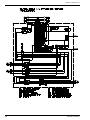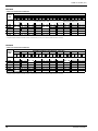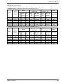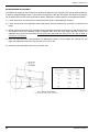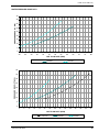
1
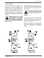
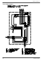
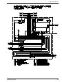
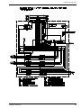
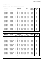
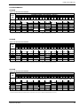
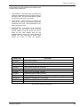
Supersedes: 145.15-IOM7 (312)
Model CSV
Vertical R-410A
Air Conditioning Units
Form 145.15-IOM7 (412)
MODEL CSV060B-240B
VERTICAL R-410A
WATER COOLED AIR CONDITIONING UNITS
INSTALLATION INSTRUCTIONS
B Style
FORM 145.15-IOM7 (412)
IMPORTANT!
READ BEFORE PROCEEDING!
GENERAL SAFETY GUIDLINES
This equipment is a relatively complicated apparatus.
During installation, operation, maintenance or service,
individuals may be exposed to certain components or
conditions including, but not limited to: refrigerants, oils,
materials under pressure, rotating components, and
both high and low voltage. Each of these items has the
potential, if misused or handled improperly, to cause
bodily injury or death. It is the obligation and responsibilty of operating/service personnel to identify and
recognize these inherent hazards, protect themselves,
and proceed safely in completing their tasks. Failure to
comply with any of these requirements could result in
serious damage to the equipment and the property in
which it is situated, as well as sever personal injury or
death to themselves and people at the site.
This document is intended for use by owner-authorized
operating/service personnel. It is expected that this
individual possesses independent training that will enable them to perform their assigned tasks properly and
safely. It is essential that, prior to performing any task
on this equipment, this individual shall have read and
understood this document and any referenced materials.
This individual shall also be familiar with and comply with
all applicable governmental standards and regulations
pertaining to the task in question.
SAFETY SYMBOLS
The following symbols are used in this document to alert the reader to areas of potential hazard.
DANGER indicates an imminently hazardous situation which, if not avoided,
will result in death or serious injury.
CAUTION identifies a hazard which
could lead to damage to the machine,
damage to other equipment and/or
environmental pollution. Usually and
instruction will be given, together with a
brief explanation.
WARNING indicates a potentially hazardous situation which, if not avoided,
could result in death or serious injury.
NOTE is used to highlight additional information which may be helpful to you.
All wiring must be in accordance with published specifications and must be performed ONLY
by qualified service personnel. Johnson Controls will not be responsible for damages/problems
resulting from improper connections to the controls or application of improper control signals.
Failure to follow this will void the manufacturers warranty and cause serious damage to property or injury to persons.
2
JOHNSON CONTROLS
FORM 145.15-IOM7 (412)
CHANGEABILITY OF THIS DOCUMENT
In complying with Johnson Controls policy for continuous product improvement, the information contained in
this document is subject to change without notice.
While Johnson Controls makes no commitment to update or provide current information automatically to the
manual owner, that information, if applicable, can be
obtained by contacting the nearest Johnson Controls
service office.
It is the responsibility of operating/service personnel as
to the applicability of these documents to the
equipment in question. If there is any question in the
mind of operating/service personnel as to the
applicability of these documents, then, prior to working
on the equipment, they should verify with the owner
whether the equipment has been modified and if
current literature is available.
TABLE OF CONTENTS
Safety Symbols………………………………………………………… 2
Changeability of This Document…………………………………….. 3
General Information……………………………………………………. 4
Installation –
Pre-Installation Inspection of Equipment………………….………4
Rigging……………………………………………………………..... 4
Installation Site……………………………………………………… 4
Unit Mounting……………………………………………………….. 5
Separation of Unit (Evaporator / Condenser)…………………… 5
Water Piping………………………………………………………… 5
Dimensional Data…..…………………………………………………. 6
Ductwork…………..…………………………………………………. 10
Blower Discharge Conversion………………………………………..10
Electrical Wiring……………………...……………………………….. 11
Typical Electrical Schematic……………………………………... 12
Nameplate Electrical Data………………………………………... 16
Fan Performance Data……………………………………………….. 17
Motor and Drive Data………………………………………………19
Blower RPM Adjustment………………………………………….. 20
Water Pressure Drop Data………………….……………………..… 21
Start-Up and Operation………………………………………………. 22
Refrigerant Charges………………………………………………. 22
Pressure Switch Settings…………………………………………. 22
Microprocessor Controller……………………………………....…… 23
Operation……………………………….………………………….. 23
Safety Switches……….…………………………………………… 23
Safety Controls…………………...........………………………….. 24
Microprocessor Flash Codes…………………………………….. 24
Maintenance/Service………………………………………………… 26
Filters………………..……………………………………………… 26
Evaporator Coil…………………………………………….............26
Refrigerant Circuits………………………………………………... 26
Blower.……………………………………………………………… 26
Drive Belts………………………………………………………….. 26
Warranty……………….………………………………………………. 27
R-410A Service Procedures - Quick Reference Guide…………...28
JOHNSON CONTROLS
3
FORM 145.15-IOM7 (412)
GENERAL INFORMATION
All models are shipped as factory-charged unitized
packages. All models are designed for freestanding
mounting on the floor, or on a field fabricated
structural steel stand. All models are shipped with
vertical evaporator fan discharge as standard. The
evaporator fan discharge configuration is field
convertible on all units.
To ensure safe installation of the unit when ceiling
mount application is specified, estimate the
approximate center of gravity of the unit. The
configuration of internal components for each unit is
different and weight is unevenly distributed.
DETERMINE THE ACTUAL CENTER OF
GRAVITY OF THE UNIT BY PERFORMING A TEST LIFT. LIFTING AN UNBALANCED UNIT CAN CAUSE PERSONAL
INJURY OR EVEN DEATH.
The 5 ton unit utilizes a single compressor. All 8 ~ 20
ton models are dual compressor units with two
independent refrigerant circuits. All units come
standard with a microprocessor control board (refer to
‘Microprocessor’ section).
ONLY QUALIFIED PERSONNEL SHOULD
PERFORM INSTALLATION AND SERVICE
OF THIS EQUIPMENT.
INSTALLATION SITE
LOCK ALL ELECTRICAL POWER SUPPLY SWITCHES IN THE OFF POSITION
BEFORE INSTALLING THE UNIT. FAILURE TO DISCONNECT POWER SUPPLY
MAY RESULT IN ELECTRICAL SHOCK
OR EVEN DEATH.
PRE-INSTALLATION INSPECTION OF EQUIPMENT
All units are factory tested to ensure safe operation
and quality assembly. Units are packaged and sealed
on shipping skids and shipped in first class condition.
Torn and broken packaging, scratched or dented
panels should be reported to carrier immediately.
Internal inspection of all units should be performed
prior to installation. Remove all access doors and
check for visual defects that can occur during
transport. Any problems found internally should be
reported to carrier and manufacturer immediately.
Refrigerant circuit should be checked to ensure no
leaks have occurred during shipment. Install gauge
set to high and low pressure ports to confirm pressure
has been maintained and no leaks have occurred
during shipment. Repair any damage prior to
installation to ensure safe operation.
Record any unit damage on the Bill of
Lading and report to carrier and factory
immediately. Shipping and handling
damages are not warranty items.
Failure to allow adequate space between
units may result in poor unit performance and possible unit failure.
Install thermostats, air supplies and returns so that
each unit will operate only on individual unit control.
To assure fast drainage of condensate run-off, unit
can be slightly pitched in the same direction as drain
pan outlet.
Unit
RIGGING
PRIOR TO MOUNTING UNIT, CHECK
INDIVIDUAL UNIT WEIGHTS (PAGE 10)
AND VERIFY LIFTING CAPACITY OF
LIFTING EQUIPMENT EXCEEDS WEIGHT
OF UNITS BY SAFE MARGINS. FAILURE
TO DO SO MAY RESULT IN UNIT
DAMAGE, PERSONAL INJURY OR EVEN
DEATH.
4
Location - To ensure unit operates at maximum
efficiencies, choose a dry indoor area where the
temperature is controlled between 50°F and 115°F.
Consideration of surrounding areas should be taken
when choosing a location to install the unit. Common
vibration and sound levels associated with commercial
equipment may be objectionable to people or
equipment.
CSV Operating Weight
Operating
Shipping
Weight (Lbs) Weight (Lbs)
CSV060B
590
635
CSV096B
795
835
CSV120B
955
995
CSV180B
1310
1365
CSV240B
1465
1525
JOHNSON CONTROLS
FORM 145.15-IOM7 (412)
UNIT MOUNTING
The 5 ~ 20 ton models are shipped as a fully
assembled integral package. If required units may be
field split to allow for passage through doors,
elevators, hallways, etc.
Duct flanges for evaporator return are incorporated
into the filter rack.
Units should be secured on a solid, level pad or sturdy
stand. The use of an isolating rubber sheet is
recommended to reduce vibration and noise
transmission. Ensure that the entire base is
continuously supported - do not support unit at corner
points only! Unit may be pitched slightly to ensure
efficient drainage of condensate.
EVAPORATOR / CONDENSER SEPARATION - (All
models)
- Reclaim the entire refrigerant charge from each
compressor circuit.
- Disconnect the evaporator motor high voltage
wires. Pull all wiring into the evaporator
compartment. Remove bushing/clamp from
routing hole for evaporator motor wiring.
- Cut and remove sections of all liquid and suction
refrigerant lines. Make two cuts in each line,
approximately 6 inches above and below the
evaporator floor/condenser roof.
Use a TUBING CUTTER ONLY - do
not use a hacksaw to cut refrigerant
tubing otherwise serious damage
can occur to refrigeration system!
- Remove corner securing brackets from the
outside corners of the cabinet, at the joint line
between the evaporator and condenser sections.
- Remove the evaporator section.
ASSEMBLY OF SPLIT UNITS - (All models)
- Place the condenser section in the required
location.
- Carefully position the evaporator section atop the
condensing section. Align all sides, the evaporator
motor wire routing hole, and the refrigerant line
routing holes.
- Use appropriate tubing couplings and splice
previously cut refrigerant lines. Pressure test
refrigerant circuits with dry nitrogen (500 psig).
- Evacuate each circuit to at least 350 microns. If
gauge pressure rises above 500 microns in one
minute, evacuation is incomplete or the system
has a leak.
- Charge circuit(s) to the value indicated on the unit
nameplate.
- Install bushing/clamp into evaporator wiring
routing hole, and pull wires through into electrical
control panel. Connect motor leads to load
terminals on contactor/overload relay.
Ensure evaporator motor rotation is
correct upon unit start-up. Switch any
two wires at contactor if blower
rotation is not correct.
WATER PIPING
All factory installed water piping terminates inside the
unit. Multi-condenser units feature manifolded single
water in and out connections.
Water connection fittings are threaded
copper. Use caution when tightening
steel pipe into copper fittings. Always
use a backing wrench on the hex
fittings inside the unit.
It is recommended that flexible connectors be
provided on the water supply and return lines if noise
and vibration transmission could be a problem.
Water piping should include shutoff / balancing valves
so that the unit can be serviced without shutting down
and draining the entire water supply circuit. Since
units are piped in parallel piping circuits, the shutoff
valves may be used to equalize the pressure drop to
each branch for even condenser water distribution. A
bibcock or a plugged tee fitting should be installed
between the shut-off valves and the unit in both the
inlet and outlet pipes. These connections are to
provide for acid cleaning of the condenser, if this
should become necessary.
- Install the securing brackets at all four corners, on
the evaporator/condenser separation joint. Note
that one bracket, intended for use at the corner
with the +drain fitting, has a short "leg".
JOHNSON CONTROLS
5
FORM 145.15-IOM7 (412)
CSV060 DIMENSIONAL DATA
6
JOHNSON CONTROLS
FORM 145.15-IOM7 (412)
CSV096-120 DIMENSIONAL DATA
JOHNSON CONTROLS
7
FORM 145.15-IOM7 (412)
CSV180 DIMENSIONAL DATA
8
JOHNSON CONTROLS
FORM 145.15-IOM7 (412)
CSV240 DIMENSIONAL DATA
JOHNSON CONTROLS
9
FORM 145.15-IOM7 (412)
DUCTWORK
When installing ductwork, adhere to local Codes and
sensible practice. Minimize duct runs and avoid abrupt
changes in direction where possible. Allow ample
access space for servicing of the coils and changing
of filters. Perform regular maintenance on ducts to
increase unit life, maintain efficient operation, and
reduce accumulation of explosive dust. Refer to
blower performance charts, and engineer duct runs
and accessory pressure drop so as not to exceed
maximum external static values.
Canvas or other types of flexible collars are
recommended for connecting the air ducts to the unit.
The supply air duct collar can be connected directly to
the blower outlet flanges. Return air may be ducted to
the unit, or drawn directly from the conditioned space
(with optional return air grille). If a ducted return is
desired, duct connection flanges may be secured
directly to the air intake opening – filters are
accessible from the right hand side.
The Manufacturer will not accept any
liability resulting from incorrect installation of this equipment. Follow installation instructions carefully.
-
Remove the panel attachments screws on the
blower outlet mounting panel. Do not remove
fasteners securing blowers to panel! The blowers
are to remain attached to the mounting panel at all
times.
-
Carefully remove the blower panel assembly from
the evaporator cabinet. Do not allow blower
housings to contact the evaporator coil during the
removal. On some models, the housing(s) will
have to be "rotated" to exit through the panel
opening.
-
Interchange the blower panel assembly with the
position of the alternate access panel. Exercise
care in locating the panel. Do not allow blower
housings to contact the evaporator coil. Install the
attachment screws and tighten securely.
-
Install the blank access panel into the remaining
evaporator opening. Fasten securely.
-
Relocate the evaporator fan drive motor to the
alternate location.
-
Install and adjust drive belts to appropriate
tension. Test run blower and observe operation
for unusual sounds or vibration.
EVAPORATOR BLOWER DISCHARGE
CONVERSION
In order to utilize the ‘rear vertical’ or ‘rear horizontal’
discharge, the upper fan module must be rotated.
All models can be field converted to the alternate
evaporator discharge orientation, as indicated on the
unit dimensional drawings. All models are shipped
with vertical fan discharge as standard.
-
The removable upper fan module that can be rotated
180° for top rear discharge applications (see below). In
addition, the blower outlet panel may be interchanged
with the front panel of the fan module. Interchanging
these two panels allows horizontal fan discharge to
either front or rear of the unit.
Procedure for converting the fan discharge from
vertical to horizontal is similar on all models, single fan
or dual fan.
-
-
10
Remove blower drive belt on all models with base
mounted motors. Remove the complete fan motor
and drive on models with blower mounted motor
assemblies.
Remove the panel attachment screws on the
alternate location access panel (front blower
module panel). The front roof support angle must
be removed to allow access to the front panel.
Remove the panel and set aside.
Disconnect power wiring at motor terminal box.
DISCONNECT
AND
LOCK
OUT
POWER WHEN SERVICING UNIT.
FAILURE TO DO SO MAY RESULT IN
PERSONAL INJURY OR DEATH DUE
TO ELECTRICAL SHOCK.
-
Remove corner connecting brackets which secure
the blower module to the lower evaporator unit.
-
Carefully lift the blower module, and rotate 1800.
Reposition the blower module on top of the
evaporator/compressor unit. Reinstall the corner
connecting brackets.
Connect new power wire leads, from the evaporator
motor contactor in the electrical box to the motor
terminal box. Ensure wires are routed clear of any
moving components. Secure the wiring so that it does
not contact the evaporator coil.
JOHNSON CONTROLS
FORM 145.15-IOM7 (412)
ELECTRICAL WIRING
Follow local electrical codes when making electrical
connections. Units are completely factory wired for
normal
supply
voltages
(ie.208-230,
460,
575V/3Ph/60Hz) Confirm unit specifications by
checking unit data plate. All electrical components are
accessible through an independent electrical panel
located on the right hand end of the
evaporator/compressor section. The electrical control
boxes are located behind outer access panels. The
compressor section electrical cover is provided with
wiring diagrams on the inside, which must be opened
to be read.
DISCONNECT AND LOCK OUT POWER
WHEN SERVICING UNIT. UNIT MAY
START AUTOMATICALLY IF POWER IS
NOT DISCONNECTED. FAILURE TO DO
SO MAY RESULT IN PERSONAL INJURY OR DEATH DUE TO ELECTRICAL
SHOCK.
Provide individual power disconnects for each unit.
Install a secure ground to the bonding lug located in
the electrical control panel. If canvas flexible joints are
used on ductwork, install a ground wire to the
ductwork as well.
All wiring must comply with applicable
local and national codes (NEC). Type
and location of disconnect switches
must comply with all applicable codes.
Unit requires installer to provide a 24volt thermostat
with appropriate heating and cooling stages as
needed. For low voltage wiring, 18 gauge wire may be
used for up to 50 feet lengths. Low voltage runs up to
125 feet require 16 gauge wire.
All models are designed for single zone cooling
applications, utilizing space or return air thermostatic
controls. A low voltage terminal block is provided for
hook-up
of
conventional
or
programmable
thermostats.
JOHNSON CONTROLS
11
FORM 145.15-IOM7 (412)
TYPICAL WIRING SCHEMATIC
12
JOHNSON CONTROLS
FORM 145.15-IOM7 (412)
JOHNSON CONTROLS
13
FORM 145.15-IOM7 (412)
14
JOHNSON CONTROLS
FORM 145.15-IOM7 (412)
JOHNSON CONTROLS
15
FORM 145.15-IOM7 (412)
ELECTRICAL DATA
ELECTRICAL DATA - STANDARD EVAPORATOR MOTOR
MODEL #
EVAPORATOR
FAN
COMPRESSOR
VOLTAGE
QTY
RLA
LRA
HP
FLA
MIN. CCT.
AMPACITY
MAX FUSE /
CCT. BKR.
AMP
CSV060B2
208-230/3/60
1
@
16.0
110.0
1.00
3.1
23.10
35
CSV060B4
460/3/60
1
@
7.8
52.0
1.00
1.5
11.25
15
CSV060B5
575/3/60
1
@
5.7
38.9
1.00
1.2
8.33
15
CSV096B2
208-230/3/60
2
@
13.1
83.1
1.50
4.5
33.98
45
CSV096B4
460/3/60
2
@
6.1
41.0
1.50
2.2
15.93
20
CSV096B5
575/3/60
2
@
4.4
33.0
1.50
1.8
11.70
15
CSV120B2
208-230/3/60
2
@
16.0
110.0
2.00
5.8
41.80
50
CSV120B4
460/3/60
2
@
7.8
52.0
2.00
2.9
20.45
25
CSV120B5
575/3/60
2
@
5.7
38.9
2.00
2.3
15.13
20
CSV180B2
208-230/3/60
2
@
23.2
164.0
3.00
8.5
60.70
80
CSV180B4
460/3/60
2
@
11.2
75.0
3.00
4.2
29.40
40
CSV180B5
575/3/60
2
@
7.9
54.0
3.00
3.4
21.18
25
CSV240B2
208-230/3/60
2
@
30.1
225.0
5.00
14.0
81.73
110
CSV240B4
460/3/60
2
@
16.7
114.0
5.00
6.6
44.18
60
CSV240B5
575/3/60
2
@
12.2
80.0
5.00
5.3
32.75
40
MIN. CCT.
AMPACITY
MAX FUSE /
CCT. BKR.
AMP
ELECTRICAL DATA - OVERSIZED EVAPORATOR MOTOR
MODEL #
QTY
16
EVAPORATOR
FAN
COMPRESSOR
VOLTAGE
RLA
LRA
HP
FLA
CSV060B2
208-230/3/60
1
@
16.0
110.0
1.50
4.5
24.50
40
CSV060B4
460/3/60
1
@
7.8
52.0
1.50
2.2
11.95
15
CSV060B5
575/3/60
1
@
5.7
38.9
1.50
1.8
8.93
15
CSV096B2
208-230/3/60
2
@
13.1
83.0
2.00
5.8
35.28
45
CSV096B4
460/3/60
2
@
6.1
41.0
2.00
2.9
16.63
20
CSV096B5
575/3/60
2
@
4.4
33.0
2.00
2.3
12.20
15
CSV120B2
208-230/3/60
2
@
16.0
110.0
3.00
8.5
44.50
60
CSV120B4
460/3/60
2
@
7.8
52.0
3.00
4.2
21.75
25
CSV120B5
575/3/60
2
@
5.7
38.9
3.00
3.4
16.23
20
CSV180B2
208-230/3/60
2
@
23.2
164.0
5.00
14.0
66.20
80
CSV180B4
460/3/60
2
@
11.2
75.0
5.00
6.6
31.80
40
CSV180B5
575/3/60
2
@
7.9
54.0
5.00
5.2
22.98
30
CSV240B2
208-230/3/60
2
@
30.1
225.0
7.50
20.4
88.13
110
CSV240B4
460/3/60
2
@
16.7
114.0
7.50
9.7
47.28
60
CSV240B5
575/3/60
2
@
12.2
80.0
7.50
7.8
35.25
45
JOHNSON CONTROLS
FORM 145.15-IOM7 (412)
FAN PERFORMANCE
CSV060B
SUPPLY AIR BLOWER PERFORMANCE
SUPPLY
CFM
AVAILABLE EXTERNAL STATIC PRESSURE - Inches W.C. ¹
0.2
0.4
0.6
0.8
1.0
1.2
1.4
1.6
1.8
2.0
RPM BHP RPM BHP RPM BHP RPM BHP RPM BHP RPM BHP RPM BHP RPM BHP RPM BHP RPM
Field Supplied Low Static
Drive
Standard Drive + 1 HP
BHP
Optional Hi-Static Drive + 1.5 HP
1600
645 0.29
733 0.36
814 0.43
888 0.50
958 0.57 1024 0.64 1087 0.72 1154 0.83 1211 0.91 1245 0.99
1800
708 0.40
788 0.48
863 0.55
933 0.63
999 0.71 1061 0.79 1121 0.87 1178 0.95 1233 1.04 1295 1.17
973 0.77 1035 0.86 1095 0.95 1152 1.04 1207 1.13 1260 1.22 1311 1.31
2000
763 0.52
837 0.61
907 0.69
2200
836 0.69
904 0.78
969 0.87 1030 0.97 1089 1.06 1145 1.15 1199 1.25 1252 1.35 1303 1.45
2400
898 0.88
961 0.98 1021 1.08 1079 1.18 1135 1.28 1188 1.38 1240 1.48
~
~
~
~
~
~
~
~
1. Blower performance includes evaporator coil and 2" filters
2. At higher evaporator airflows and wet bulb conditions, condensate carry-over may occur. Decrease airflow downward as necessary.
CSV096B
SUPPLY AIR BLOWER PERFORMANCE
SUPPLY
CFM
AVAILABLE EXTERNAL STATIC PRESSURE - Inches W.C. ¹
0.2
0.4
0.6
0.8
1.0
1.2
1.4
1.6
1.8
2.0
RPM BHP RPM BHP RPM BHP RPM BHP RPM BHP RPM BHP RPM BHP RPM BHP RPM BHP RPM
Field Supplied Low Static
Drive
Standard Drive + 1.5 HP
BHP
Optional Hi-Static Drive + 2 HP
2400
510 0.31
600 0.45
672 0.60
741 0.78
810 0.96
878 1.14
936 1.33
2800
538 0.44
628 0.57
700 0.71
778 0.89
830 1.10
890 1.29
950 1.50 1010 1.72 1048 1.92
985 1.78 1037 1.99
3200
599 0.62
675 0.79
745 0.98
815 1.18
875 1.38
927 1.58
3600
661 0.86
730 1.03
795 1.23
853 1.43
915 1.64
973 1.85
4000
712 1.10
773 1.28
830 1.50
888 1.72
946 1.95
~
~
982 1.54 1033 1.76 1074 2.00
~
~
~
~
~
~
~
~
~
~
~
~
~
~
~
~
~
~
~
~
~
~
1. Blower performance includes evaporator coil and 2" filters
2. At higher evaporator airflows and wet bulb conditions, condensate carry-over may occur. Decrease airflow downward as necessary.
CSV120B
SUPPLY AIR BLOWER PERFORMANCE
SUPPLY
CFM
AVAILABLE EXTERNAL STATIC PRESSURE - Inches W.C. ¹
0.2
0.4
0.6
0.8
1.0
1.2
1.4
1.6
1.8
2.0
RPM BHP RPM BHP RPM BHP RPM BHP RPM BHP RPM BHP RPM BHP RPM BHP RPM BHP RPM
Field Supplied Low Static
Drive
Standard Drive + 2 HP
BHP
Optional Hi-Static Drive + 3 HP
3200
599 0.62
675 0.79
745 0.98
815 1.18
875 1.38
927 1.58
984 1.78 1037 1.99 1082 2.22 1128 2.42
3600
661 0.86
730 1.03
795 1.23
853 1.43
915 1.64
973 1.85 1020 2.10 1070 2.37 1114 2.67 1160 2.89
4000
712 1.10
773 1.28
830 1.50
888 1.72
946 1.95 1004 2.19 1062 2.44 1098 2.70 1146 2.97
4400
768 1.42
824 1.62
877 1.82
930 2.04
985 2.30 1035 2.60 1085 2.90
4800
822 1.78
875 1.98
925 2.20
975 2.43 1026 2.68 1078 2.96
~
~
~
~
~
~
~
~
~
~
~
~
~
~
~
~
1. Blower performance includes evaporator coil and 2" filters
2. At higher evaporator airflows and wet bulb conditions, condensate carry-over may occur. Decrease airflow downward as necessary.
JOHNSON CONTROLS
17
FORM 145.15-IOM7 (412)
CSV180B
SUPPLY AIR BLOWER PERFORMANCE
SUPPLY
CFM
AVAILABLE EXTERNAL STATIC PRESSURE - Inches W.C. ¹
0.2
0.6
0.4
0.8
1.0
1.2
1.4
1.8
1.6
2.0
RPM BHP RPM BHP RPM BHP RPM BHP RPM BHP RPM BHP RPM BHP RPM BHP RPM BHP RPM
Field Supplied Low Static
Drive
Standard Factory Drive + 3 HP
BHP
Optional Hi-Static Drive + 5 HP
4800
634 1.20
697 1.42
757 1.62
813 1.84
867 2.06
918 2.30
5400
701 1.66
758 1.90
812 2.14
864 2.38
914 2.62
962 2.88 1009 3.12 1053 3.38 1097 3.66 1139 3.92
6000
765 2.22
817 2.48
867 2.74
916 3.00
962 3.28 1007 3.54 1051 3.82 1093 4.10 1134 4.38 1174 4.68
972 3.76 1015 4.06 1057 4.34 1099 4.64 1139 4.96
6600
832 2.90
880 3.20
927 3.48
7200
900 3.72
945 4.02
988 4.34 1030 4.64 1070 4.96
~
~
968 2.52 1015 2.76 1065 3.02 1109 3.32
~
~
~
~
~
~
~
~
~
~
~
~
1. Blower performance includes evaporator coil and 2" filters
2. At higher evaporator airflows and wet bulb conditions, condensate carry-over may occur. Decrease airflow downward as necessary.
CSV240B
SUPPLY AIR BLOWER PERFORMANCE
SUPPLY
CFM
AVAILABLE EXTERNAL STATIC PRESSURE - Inches W.C. ¹
0.2
0.4
0.6
0.8
1.0
1.4
1.2
1.6
1.8
2.0
RPM BHP RPM BHP RPM BHP RPM BHP RPM BHP RPM BHP RPM BHP RPM BHP RPM BHP RPM
Field Supplied Low Static Drive
Standard Factory Drive + 5 HP
BHP
Optional Hi-Static Drive +7.5HP
6400
705 1.96
760 2.22
812 2.48
862 2.72
910 3.02
956 3.28 1001 3.56 1043 3.84 1085 4.12 1125 4.42
7200
788 2.76
837 3.06
884 3.34
930 3.64
952 3.78
995 4.08 1037 4.38 1078 4.70 1118 5.00 1156 5.32
8000
861 3.70
906 4.02
950 4.34
992 4.66 1033 4.98 1073 5.32 1111 5.66 1149 5.98 1186 6.32 1222 6.68
8800
949 4.94
970 5.12 1010 5.46 1049 5.82 1087 6.18 1125 6.52 1161 6.90 1197 7.26
9600
1028 6.34 1066 6.72 1103 7.10 1139 7.48
~
~
~
~
~
~
~
~
~
~
~
~
~
~
~
~
1. Blower performance includes evaporator coil and 2" filters
2. At higher evaporator airflows and wet bulb conditions, condensate carry-over may occur. Decrease airflow downward as necessary.
18
JOHNSON CONTROLS
FORM 145.15-IOM7 (412)
MOTOR AND PULLEY DATA
EVAPORATOR-STANDARD BLOWER MOTOR AND DRIVE DATA
Adjustable
Motor
Motor Pulley
Drive
Model
Range
Pitch
Browning
Frame
Eff.
(RPM)
Dia.
HP
Size
(%)
(in)
Part No.
CSV060B
745-1117
1
CSV096B
614-921
CSV120B
711-984
CSV180B
CSV240B
1.9-2.9
1VP34X7/8
Blower Pulley
Pitch
Browning
Dia.
(in)
Part No.
1.5
145
88.5
1.9-2.9
1VP34X7/8
5.7
AK59H
AX35
2
145
88.5
2.4-3.4
1VP40X7/8
6.4
AK66H
AX37
724-925
3
184
90.2
3.4-4.4
1VP50X1 1/8
8.7
AK89H
AX39
848-1064
5
184
90.2
4.7-5.9
1VP60X1 1/8
9.7
BK100H
BX60
1.5
145
88.5
1.9-2.9
1VP34X7/8
AK49H
Rating/Size
88.5
897-1346
4.7
Belts
145
EVAPORATOR-OVERSIZED BLOWER MOTOR AND DRIVE DATA
Adjustable
Motor
Motor Pulley
Drive
Model
Range
Pitch
Browning
Frame
Eff.
(RPM)
Dia.
HP
Size
(%)
(in)
Part No.
CSV060B
Fixed
Fixed
Blower Pulley
Pitch
Browning
Dia.
(in)
Part No.
3.9
AK41H
A29
Belts
Rating/Size
A28
CSV096B
798-1105
2
145
88.5
2.4-3.4
1VP40X7/8
5.7
AK59H
AX36
CSV120B
875-1118
3
184
90.2
3.4-4.4
1VP50X1 1/8
7.2
AK74H
AX36
CSV180B
894-1122
5
184
90.2
4.7-5.9
1VP60X1 1/8
9.2
BK95H
BX40
CSV240B
1046-1287
7.5
213
90.2
5.2-6.4
1VP65X1 3/8
10.2
BK90H
BX57
JOHNSON CONTROLS
19
FORM 145.15-IOM7 (412)
BLOWER SPEED ADJUSTMENT
The RPM of the supply air and condenser air blowers will depend on the required CFM, and the static resistances
of both the supply/discharge and the return/intake duct systems. With this information, the RPM for the blowers
can be determined from the blower performance tables. Adjustment of blower speed is accomplished as follows:
1) Loosen belt tension by moving motor towards the blower shaft via the adjustable mounting.
2) Loosen the setscrew in the adjustable motor pulley flange. Remove external key on pulleys 4 in. diameter and
larger.
3) Blower speed will increase when moveable flange is adjusted towards the fixed flange (closed). Blower speed
will decrease when the moveable flange is adjusted away from the fixed flange (opened). Pulleys are
adjustable only in half-turn increments. Do not open pulley more than five full turns for "4L" and "A" belts, or
six full turns for "B" belts.
4) Once the pulley has been opened/closed the appropriate number of turns, replace the external key and
tighten the adjustment setscrew. Proper torque is 110-130 in.-lbs.
5) Install drive belt and adjust motor mount to tension belt.
BELT TENSION ADJUSTMENT
LD13547
DEFLECTION FORCE VERSUS DRIVE BELT CROSS-SECTION
20
JOHNSON CONTROLS
FORM 145.15-IOM7 (412)
WATER PRESSURE DROP DATA
45
PRESSURE DROP (FT H20)
40
35
30
25
20
15
10
5
0
20
25
30
35
40
45
50
55
60
65
70
75
80
UNIT FLOW RATE (GPM)
CSV240
CSV180
40
PRESSURE DROP (FT H20)
35
30
25
20
15
10
5
0
6
8
10
12
14
16
18
20
22
24
UNIT FLOW RATE (GPM)
CSV120
JOHNSON CONTROLS
CSV096
26
28
30
32
34
CSV060
21
FORM 145.15-IOM7 (412)
START-UP AND OPERATION
Start unit and check rotation of fans and compressors.
Scroll compressors will only compress in one
rotational direction. Three phase compressors will
rotate in either direction depending upon phasing of
the power. Since there is a 50-50 chance of
connecting power in such a way as to cause rotation
in the reverse direction, it is important to ensure
proper rotation direction is achieved when the
system is installed and operated.
Monitor the microprocessor board for any fault codes.
This will ensure proper unit operation. Verification of
proper compressor direction is made by observing
that suction pressure drops and discharge pressure
rises when the compressor is energized. Reverse
compressor rotation also results in an elevated sound
level as well as substantially reduced current draw.
There is no negative impact on durability caused by
operating three phase Scroll compressors in the
reversed direction for a short period of time (under
one hour). However, after several minutes of
operation the compressors internal protector will trip.
If opposite rotation is needed, disconnect and reverse
any two leads of the three phase supply. Reconnect
power.
Observe unit operation and check for
unusual noise or vibration.
The Air Conditioning section of this
equipment is charged with R-410A; a
hi-pressure refrigerant. Only qualified
technicians, using appropriately
pressure-rated test instruments,
should perform troubleshooting or
service on this equipment.
Pressure Switch Settings - All Models
High
Low
Cut Out (PSIG)
600
50
Cut In (PSIG)
450
75
Refrigerant Charge (LBS)
UNIT
Circuit 1
Circuit 2
CSV060B
5.25 (5 lbs 4 oz)
-
CSV096B
5.18 (5 lbs 3 oz)
5.30 (5 lbs 5 oz)
CSV120B
6.12 (6 lbs 2 oz)
6.25 (6 lbs 4 oz)
CSV180B
8.69 (8 lbs 11oz)
9.12 (9 lbs 2 oz)
CSV240B
12.45 (12 lbs 7 oz)
12.45 (12 lbs 7 oz)
22
JOHNSON CONTROLS
FORM 145.15-IOM7 (412)
MICROPROCESSOR CONTROLLER
The microprocessor control system is specifically
designed for single and dual stage systems. The
control system interfaces with a conventional type
thermostat.
•
Unit shall be complete with self-contained lowvoltage control circuit
•
Unit shall incorporate a lockout circuit which
provides reset capability at the space thermostat
or base unit, should any of the following standard
safety devices trip and shut off compressor.
-
Loss-of-charge/Low-pressure switch
-
High-pressure switch
-
Condensate Overflow protection switch
•
Unit shall operate with conventional thermostat
designs and have a low voltage terminal strip for
easy hook-up.
•
Unit control board shall have on-board diagnostics
and fault code display.
When the room t-stat calls for cooling, the low-voltage
control circuit from “R” to “Y1”and “G” is completed.
The compressor and fan motor are energized. After
completing the specified fan on delay for cooling, the
microprocessor control will energize the blower motor.
Once the room t-stat has been satisfied, it will deenergize “Y1”. If the compressor has satisfied its
minimum run time, the compressor and fan deenergize. Otherwise, the unit operates the cooling
system until the minimum run time for the compressor
has been completed. After the compressor deenergizes, the blower is stopped following the elapse
of the fan-off delay for cooling.
To be available, a compressor must not be locked-out
due to a high-pressure switch; low- pressure switch;
condensate overflow switch; and the anti-short cycle
delay (ASCD) must have elapsed.
SAFETY SWITCHES
Each refrigerant system is monitored to ensure it does
not operate outside of its intended operating
parameters. Safety switches are handled as described
below. All system errors override minimum run times
for compressors.
•
Standard controls shall include anti-short cycle
and low voltage protection
•
Control board shall monitor each compressor and
refrigerant safety switch independently.
•
Control board shall have random start feature
High-Pressure Limit Switch
•
Control board shall retain last 5 fault codes in non
volatile memory which will not be lost in the event
of a power loss.
If a high-pressure limit switch opens, the
microprocessor control de-energizes the compressor,
initiates the ASCD, and stops the fan. If a call for
cooling or heating is still present at the conclusion of
the ASCD, the microprocessor control will re-energize
the compressor and unit fan.
OPERATION
For cooling the room t-stat energizes the low-voltage
circuit between “R” & “Y1”.
The call is passed to the unit microprocessor control,
which then determines whether the requested
operation is available and, if so, which components to
energize.
CONTINUOUS BLOWER
By setting the room t-stat fan switch set to “ON”, the
supply air blower will operate continuously. With the
room t-stat fan switch set to “AUTO”, the blower is
energized whenever a cooling operation is requested.
The blower is energized after any specified delay
associated with the operation.
When energized, the indoor blower has a minimum
run time of 30 seconds. Additionally, the indoor blower
has a delay of 10 seconds between operations.
Should a high-pressure switch open three times within
two hours of operation, the microprocessor control will
permanently lock-out the compressor. The system
must be manually reset by de-energizing the 24 volt
power to unit, or turning the room t-stat to the “OFF”
position then back to cooling position. The
microprocessor control will flash a fault code
indicating a high-pressure lock-out.
Low-Pressure Limit Switch
The low-pressure limit switch is not monitored during
the initial 30 seconds of compressor operation. After
the initial 30 seconds have passed, the
microprocessor control will monitor the low-pressure
switch for another 30 seconds. If the low-pressure
switch fails to close after the 30 second monitoring
phase, the microprocessor control will de-energize the
compressor, initiate the ASCD, and stop the fan.
Once the low-pressure switch has been proven
(closed during the 30-second monitoring period as
JOHNSON CONTROLS
23
FORM 145.15-IOM7 (412)
described above), the microprocessor control board
will continue to monitor the low-pressure limit switch
for any openings. If the low-pressure switch opens for
greater than 5 seconds, the microprocessor control
board will de-energize the compressor, initiate the
ASCD, and stop the fan.
If the call for cooling is still present at the conclusion
of the ASCD, the microprocessor control will reenergize the compressor.
Should a low-pressure switch fault three (3) times
within one (1) hour of operation, the microprocessor
control board will lock-out the compressor and flash a
fault code indicating a low-pressure lock-out.
is utilized to prevent short cycling of the compressor.
Additionally, a minimum run time is imposed any time
a compressor is energized. The ASCD is initiated on
unit start-up and on any compressor reset or lockout.
Microprocessor Control Unit Flash Codes
Various flash codes are utilized by the microprocessor
control to aid in troubleshooting. Flash codes are
distinguished by the short on and off cycle used
(approximately 200ms on and 200ms off). To show
normal operation, the control boards flash a 1 second
on, 1 second off “heart beat” during normal operation.
This is to verify that the microprocessor is functioning
correctly. Do not confuse this with an error flash code.
To avoid confusion the 1-flash, fault code is not used.
Condensate Overflow Switch
A Condensate Overflow fault occurs when the
Condensate Overflow switch opens for more than two
line cycles. The compressor is shutdown regardless
of Minimum Run Time, ASCD is initiated, and alarm is
tripped. The fan continues operating in its current
state.
Compressor will re-energize once the
Condensate Overflow switch closes, and ASCD has
been satisfied and a call for cooling is still present.
The microprocessor control board logs the first
incident per compressor request. If the compressor
request is removed, the fault occurrence counter is
reset to zero. Should the Condensate Overflow
switch open three within two hours of run time, the
microprocessor control board will lock-out the
compressor, turn off the fan and flash a fault code
indicating a Condensate Overflow lock-out.
SAFETY CONTROLS
The microprocessor control monitors the following
inputs:
1. A High-Pressure Switch on each compressor
circuit to protect against excessive discharge
pressures.
2. A Low-Pressure Switch on each compressor
circuit to protect against loss of refrigerant charge.
3. A Condensate Overflow Switch to protect against
condensate overflow.
Compressor Protection
In addition to the external pressure switches, the
compressor also has inherent (internal) protection. If
there is an abnormal temperature rise in a
compressor, the internal protection will immediately
shut down the compressor. The microprocessor
control incorporates features to minimize compressor
wear and damage. An anti-short cycle delay (ASCD)
24
JOHNSON CONTROLS
FORM 145.15-IOM7 (412)
Current alarms or active restrictions are flashed on the
microprocessor control LED.
1. LAST ERROR – When this button is pressed and
released, it flashes the last five (5) flash codes on
the board’s LED. The most recent alarm is shown
first and the oldest alarm is shown last.
2. TEST RESET – When this button is pressed and
released, any anti-short cycle delays (ASCD) are
bypassed for one cycle. When pressed twice, any
active lockouts are reset.
3. COMM SETUP – If the board is to be networked
with other units, this button is used to set the
network address. Press the button once and it
scans the bus, then assigns itself the first
available address, (starts at 2). It then flashes that
address one time. Pressing the button twice
causes the control to flash the address.
FLASH CODES
On Steady
2 Flashes
3 Flashes
4 Flashes
5 Flashes
6 Flashes
7 Flashes
11 Flashes
13 Flashes
14 Flashes
OFF
Description
This is Control Failure
Control waiting ASCD (Anti-Short Cycle Delay) *
High Pressure Compressor 1 Lockout
High Pressure Compressor 2 Lockout
Low Pressure Compressor 1 Lockout
Low Pressure Compressor 2 Lockout
Condensate Overflow Switch Lockout
Compressor(s) locked out due to Economizer running (Free Cooling) *
Compressor Held Off due to Low Voltage
EEPROM Storage Failure
No Power or Control Failure
Note: Flash rates marked with * are NOT alarms.
JOHNSON CONTROLS
25
FORM 145.15-IOM7 (412)
MAINTENANCE / SERVICE
DRIVE BELT DISCONNECT AND LOCK OUT
POWER WHEN SERVICING UNIT.
FAILURE TO DO SO MAY RESULT IN
PERSONAL IN-JURY OR DEATH
DUE TO ELECTRICAL SHOCK.
Exercise care when working around
the sharp metal edges of door panels
or door frames, etc. These edges can
cause injury.
EVAPORATOR COIL
Inspect the evaporator coil at filter change intervals.
Dirty or clogged evaporator coils causes low suction
pressure and lost capacity. If the coils appear dirty,
they should be cleaned using a mild detergent or a
commercial coil cleaning agent.
REFRIGERANT CIRCUIT(S)The Air Conditioning section of this
equipment is charged with R-410A; a high
pressure refrigerant. Only qualified
technicians, using appropriately pressure rated test instruments, should
perform troubleshooting or service on
this equipment.
With the unit operating, check and record the
compressor discharge and suction pressures. The
compressor running current should also be recorded.
A maintenance log of these readings can indicate if
the unit is operating within its normal limits. Abnormal
readings should be investigated, and the Cause
corrected.
Examine belt periodically for wear. Glazed areas on
the drive surfaces indicate overheating due to belt
slippage. Ideal tension is the lowest tension at which
the belt will not slip under peak load conditions. Overtensioning shortens belt and bearing life (see section
‘Blower Speed Adjustment’).
The tension on the belt should be adjusted for a
deflection of 1/64 of an inch per inch of belt span, with
the appropriate force applied at the midpoint of the
span (see section ‘Blower Speed Adjustment’).
Tension “New” belts at the maximum value indicated.
Used belts should be maintained at the minimum
value.
FILTERS Inspect filters monthly and replace as necessary. Use
UL Class 2 rated filters. Factory supplied filters are
medium efficiency, extended surface pleated type.
Replacements should be of the same type, to
maintain optimum airflow performance. Filter sizes are
as follows:
Filters
Qty/Size
CSV060B
2/20x16x2
CSV096B
6/14x20x2
CSV120B
6/14x20x2
CSV180B
2/16x20x2
4/16x25x2
CSV240B
6/20x25x2
BLOWER Inspect the evaporator blower at each regular service
interval. Clean blower wheel as needed. Bearings are
permanently sealed ball type, and do not require
lubrication. Check bearings for any signs of wear
(movement between inner and outer races). Ensure
bearing locking collars are secure to the shaft, and
that collar locking screw is properly set. Check that
the blower wheel is tight on the shaft, and that the hub
set
screws
are
properly
torqued.
26
JOHNSON CONTROLS
FORM 145.15-IOM7 (412)
R-410A QUICK REFERENCE GUIDE
Refer to Installation Instructions for specific installation requirements.
•
R-410A Refrigerant operates at 50 - 70 percent higher pressures than R-22. Be sure that servicing
equipment and replacement components are designed to operate with R-410A.
•
R-410A Refrigerant cylinders are rose colored.
•
Recovery cylinder service pressure rating must be 400 psig. DOT 4BA400 or DOT BW400.
•
Recovery equipment must be rated for R-410A.
•
Do not use R-410A service equipment on R-22 systems. All hoses, gages, recovery cylinders,
charging cylinders and recovery equipment must be dedicated for use on R-410A systems only.
•
Manifold sets must be at least 700 psig high side, and 180 psig low side, with 550 psig retard.
•
All hoses must have a service pressure rating of 800 psig.
•
Leak detectors, must be designed to detect HFC refrigerants.
•
Systems must be charged with refrigerant. Use a commercial type metering device in the manifold
hose.
•
R-410A can only be used with POE type oils.
•
POE type oils rapidly absorb moisture from the atmosphere.
•
Vacuum pumps will not remove moisture from POE type oils.
•
Do not use liquid line driers with a rated working pressure rating less than 600 psig.
•
Do not install suction line driers in the liquid line.
•
A liquid line drier is required on every unit.
•
Do not use an R-22 TXV. If a TXV is to be used, it must be an R-410A TXV.
•
Never open system to atmosphere when under vacuum.
•
If system must be opened for service, evacuate system then break the vacuum with dry nitrogen and
replace filter driers.
JOHNSON CONTROLS
27
FORM 145.15-IOM7 (412)
Subject to change without notice. Printed in U.S.A.
Copyright© 2012 by Unitary Products Group. All rights reserved.
Engineered Systems
Products
Group
Form 145.15-IOM7 (412)
P.O. Box 1592
York, PA
17405
York
PA
17405