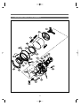
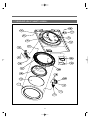
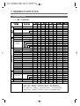
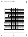
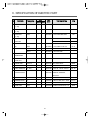
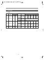
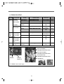
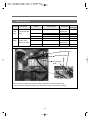
1
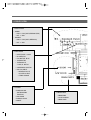
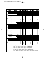
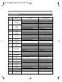
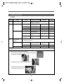
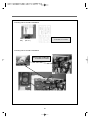
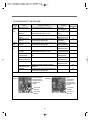
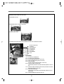
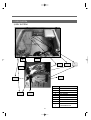
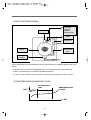
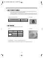
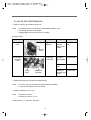
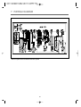
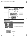
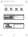
Service Manual
KUD-WC1113
KUD-WD1117
DRUM WASHING MACHINE
SERVICE GUIDE
1. WHAT IS DRUM? ...............................................................2
2. SPECIFICATION OF DRUM WASHING MACHINE ......................6
3. VERIFICATION OF DRUM ASSY............................................7
4. PARTS LIST FOR EACH ASSY...............................................9
5. SEQUENCE CHART OF PCB...............................................21
6. SPECIFICATION OF ELECTRONIC PARTS ..............................31
7. WIRING DIAGRAM........................................................... 50
8. TROUBLESHOOTING REGARDING DRAIN .............................51
9. INSTALLATION GUIDE ......................................................52
10. ATTENTION POINT WITH SERVICE .....................................54
1. WHAT IS DRUM ?
1. WHAT IS DRUM WASHER?
One of the famous washers in the globe which uses laundry falling energy.
2. Sales point of our washer
◈ The biggest capacity with compact size
◈ No damage and entanglement but excellent washability
◈ 4way savings-noise, vibration, washing times, energy
◈ Self-cleaning course of Drum
◈ Good washing performance with heating system
◈ Condensing dry system with saving energy
◈ Big door glass with easy laundry take-in/out
◈ The higest spin speed
2
3. THE DRIVE SYSTEM OF DRUM WASHING MACHINE
TUB
WASH
DRUM
DRAIN
PUMP
LIFTER
BLDC
• DD CONTROL : DIRECT DRIVE TYPE
• BLDC MOTOR
3
4. DRIVE SYSTEM
3. INLET PARTS
•COMBO
- COLD : 3-WAY (COLD, PREWASH, DRY)
- HOT : 1-WAY
•WASHER
- COLD : 2-WAY (COLD, PREWASH)
- HOT : 1-WAY
6. DRY PARTS
• HEATER DRY : 1300W
• BLOWER FAN
• FAN MOTOR : BLDC
• THERMISTOR
• THERMOSTAT
: FUSE, BI-METAL
• CONDENSING SYSTEM
• DRY FAN DRIVE
-` GENERATION OF
HEATER’
S HEAT
-` TEMP. SENSOR
DRAIN PARTS
5. DOOR부
•DOOR LOCK S/W
: WATER ADDING
FUNCTION
•LOCK HINGE
•DOOR AS : GLASS
•GASKET
7. DRAIN PARTS
•DRAIN PUMP
•VALVE HOUSING
•DRAIN HOSE I
4
1. CONTROLLER
•MAIN PCB
•FRONT PCB
•HARNESS
•NOISE FILTER
•POWER CORD : 13A
2. DRIVE PARTS
•BLDC MOTOR
•DRUM
•BEARING
•SPIDER/SHAFT
•TUB
•WEIGHT BALANCER
4. WASH HEATING
•WASH HEATER : 1000W
•THERMISTOR
8. SUPPORTER
•BASE
•DAMPER AS : 4(70N)
5
2. SPECIFICATION OF DRUM WASHING MACHINE
1. PANEL TYPE 1
DIMENSION(WxDxH)
686mm(W) x 807mm(D) x 1020mm(H)
MACHINE WEIGHT
96 ㎏
POWER SOURCE
120V / 60Hz
POWER
WASHING
CONSUMPTION
DRY
10 A
11.5 A
WASHING TYPE
DRUM TYPE
DRY TYPE
OPERATION WATER PRESSURE
Digital condensing dry system
29kPa ~ 784kPa(0.3㎏f/cm2~8㎏f/cm2)
6
3. VERIFICATION OF DRUM ASSY
7
8
4. PARTS LIST FOR EACH ASSY
1. THE EXPLODED VIEW OF CABINET ASSEMBLY
9
No.
PARTS NAME
PARTS CODE
DESCRIPTION
UNITS REMARK
C01
CABINET
3610811730
SGCC 0.8T, PUMP COMBO
1
C02
FRAME LOWER
3612206700
SBHG 1.2T
1
C03
FRAME TOP L
3612206500
SGCC 1.6T
1
C04
FRAME TOP R
3612206600
SGCC 1.6T
1
C05
FRAME UPPER
3612206400
SBHG 1.2T
1
C06
STOPPER SPRING
3615202200
POM
2
FIXTURE PLATE
3612008000
POM
8
SCREW TAPPING
7121401211
T2S PAN 4X12 MFZN
8
C08
NOZZLE AIR
3618103110
PP
1
C09
HANDLE CABINET
3612608100
PP
2
C10
COVER BACK AS
3611425510
COVER B + PAD CABINET
1
C12
SENSOR PRESSURE
3614825220
DWD-130RP
1
C13
REACTOR
52G043A110
UL L=150MM
1
C14
UNIT DRAIN PUMP AS
36189L5600
PUMP+FILTER
1
C15
HOSE DRAIN I AS
3613271200
PUMP HOSE
1
C16
HOSE WATER REMAIN
3613271400
EPDM
1
C17
CAP WATER REMAIN
3610916800
PP
1
C18
GUIDE DRAIN HOSE
3612510400
PP
1
C19
PCB AS
3610PCB490 MEX COMBI
1
COMBO
3610PCB495 MEX WASHER
1
WASHER
C07
C11
C20
COVER PCB M
3611427700
UL,ABS VE-0856, MAIN PCB
10
1
BASE U
2. THE EXPLODED VIEW OF BASE U ASSEMBLY
No.
B01
B02
B03
B04
B05
B06
B07
PARTS NAME
EMI FILTER
BASE U
ABSORBER BASE
SUPPORTER LEG
FIXTURE LEG
FOOT
SPECIAL BOLT
PROTECTOR HEATER
PARTS CODE
3611908700
3610392700
3610115400
3615303600
3612006400
3612100600
3616029000
3618304600
11
DESCRIPTION
DWLF-K23
PP
PEM, 12X1500, 25T
3.0T
ABS, DWD-100DR
BUTYL, DWD-100DR
10 X 1.25, 51MM
SECC 0.35T
UNITS
1
1
1
4
4
4
4
1
REMARK
3. THE EXPLODED VIEW OF TUB ASSEMBLY
12
No.
PARTS NAME
PARTS CODE
DESCRIPTION
UNITS REMARK
H01
BALANCER WEIGHT AS(L) 3616106900
13KG DRUM
1
H02
BALANCER WEIGHT AS(R) 3616106800
13KG DRUM
1
H03
GASKET
3612321900
EPDM
1
COMBO
3612322000
EPDM
1
WASHER
H04
CLAMP GASKET AS
3611205300
WIRE
1
H05
SPRING SUSPENSION
3615114800
13KG DRUM
2
H06
TUB FRONT
3618828Y00
FRPP
1
H07
FIXTURE HEATER
3612006700
SUS
1
H08
DAMPER PIN
361A700200
AKS D=14.5
4
H09
DAMPER FRICTION
361A700110
70N AKS ST=170-260 DL=197.5
4
H10
DRUM AS
3617008X00
SUS
1
H11
LIFT AS
361A400510
NON-NANO, SUS FILTER
3
H12
SPIDER AS
361A300600
ALDC+S45C
1
H13
-
-
-
H14
HOSE DRAIN
3613269000
EPDM,PUMP
1
H15
AIR TRAP AS
3610AAR600
HOSE+TRAP
1
H16
GASKET TUB
3612321100
EPDR FORM
1
H17
WATER SEAL
361A600200
NBR
1
H18
BEARING INNER
3616303800
6306DD
1
H19
BEARING HOUSING
3616303700
ALDC
1
H20
BEARING OUTER
3616303900
6305DD
1
H21
HOSE AIR
3613266300
EPDM
1
H22
BASE
3610392600
SESEN
1
H22
UNIT STATOR BL C
-
36189L4810 ¥Õ265X30H,36SLOT,2SNESOR,WS2A30G001
H24
UNIT ROTOR BLDC
36189L4900
H26
HEATER WASH
3612801740
H27
UNIT BUBBLE PUMP
36189L4130
MAGNET24,SERRATION,WR1238F001
1
120V 1KW.1R0A721005.RW8TF1PE.IRCA
100-130 DBK-115DC RP-CUSH COM.
13
1
1
1
4. THE EXPLODED VIEW OF DUCT B AS AND DUCT PIPE ASSEMBLY
14
No.
PARTS NAME
PARTS CODE
DESCRIPTION
E01
UNIT FAN MOTOR
36189L3Z10
ISM-77806DWWA 24V CW 8P 14W
1
E02
DUCT COVER
361A200400
AL, 2.5T
1
E03
DUCT B UPPER AS
361A200670
ALCOSTA UPPER, NON-COATING
1
E04
CLAMP CORD
3611203330
DABE-2 A=9 B=5.3 L=105
4
E05
FAN AS
3611885900
D133 FAN, GFPP30% _- NYLON66
1
E06
SCREW TAPPING
7122400811
T2S TRS 4x8 MFZN
1
E07
WASHER PLAIN
7400432011
PW 4.3*20*1T
1
E08
FUSE TEMPERATURE
361A800130
128℃,DF-128S,15A,250V,VDE
1
E09
FRAME HEATER FRANGE
3612206200
SBHG
1
E10
DUCT B LOWER
361A200101
AL, 3T
1
E11
PACKING THERMOSTAT 3614009900
SILICON
1
E12
SWITCH THERMOSTAT
3619046 500
UL,150ON-120OFF,125V/15A,250V/10A
1
E13
HEATER DRY
3612802100
120V/1.3KW_12OHM3.5W/SQ.INCOLOY800.RA8.1R3A034008
1
E14
THERMISTOR DRY
361AAAAC00
UL APPROVED.R40=26.065K.R90=4.4278K
1
E15
PACKING RUBBER
3614009800
SILICON
1
E16
CUSHION DRY
3611562800
NBR
2
E17
GASKET SEAL B
3612320810
EPDM FOAM, L=412, 4.9*4.4*4.8
1
E18
GASKET SEAL A
3612320820
Φ5,L=1385
1
E19
GASKET INLET
3612320900
DWD-100DR
1
E20
DUCT GUIDE
361A201700
ALDC
1
E21
DUCT PIPE AS
361A201400
13KG
1
E22
CLAMP AS(DUCT)
3611203700
DUCT
1
E23
BELLOWS DUCT
3616403000
EPDM
1
15
UNITS REMARK
5. THE EXPLODED VIEW OF INLET BOX ASSEMBLY
No.
I01
I02
I03
I04
I05
I06
I07
I08
I09
I10
I11
I12
I13
I14
I15
I16
I17
I18
PARTS NAME
INLET BOX
HOSE INLET
CLAMP AS
NOZZLE AS
HOSE HOT
HOSE MAIN
HOSE C
PIPE JOINT(HOSE INLET)
HOSE SHOWER
CLAMP SPRING
CLAMP
CASE DETERGENT
PARTS CODE
3617505800
3613270300
3611203200
3618103500
3613270400
3613270500
3613267020
3614413300
3613270110
3611203800
4507D08152
3611141800
DESCRIPTION
ABS
EPDM
ID=60, WIRE+GUIDE+BOLT+NUT
PP
EPDM, ID=10, OD=16, L=460mm
EPDM, ID=10, OD=16, L=410mm
EPDM, ID=10, OD=16, L=230mm
PP
EPDM, L=590mm
ID=15.5, T=0.6, B=10
HOSE ID=7
ABS
VALVE INLET
I19
VALVE INLET
UNITS REMARK
1
1
2
1
1
1
2
1
1
8
2
1
CAP SOFTENER
CASE HANDLE
HANDLE CAP
3610917200
3611141700
3612609100
PP
ABS
ABS
1
1
1
3615415700
UL.120V60HZ.BITRON.1WAY
1
3615415070 100~130V,3WAY,RINSE GUIDEÀ,PP/BRACKET 1
16
1
6. THE EXPLODED VIEW OF CABINET F ASSEMBLY
17
No.
PARTS NAME
PARTS CODE
DESCRIPTION
UNITS REMARK
F01
CABINET F
3610811820
SECD 1.0T PUMP
1
F02
SUPPORT HINGE
3615304000
SGCC 1.6T
1
F03
LABEL SAFETY R
3613555800
PVC
1
F04
LABEL DRY R
3613555900
PVC
1
DOOR AS
361A110800
130RP'S DOOR AS
1
F05
FRAME DOOR IN
3612206800
TB53
1
F06
STOPPER DOOR
3615202300
PP
1
F07
DOOR GLASS
361A110600
GLASS
1
F08
PROTECTOR GLASS
3618304300
PC
1
F09
HINGE DOOR
3612902900
ALDC
1
F10
CAP HINGE DOOR
3610916500
POM
4
F11
FRAME DOOR OUT
3612206900
CR BASE, 732G
1
F12
SCREW TAPPING
7115402008
T1S FLT 4x20 SUS430
16
F13
COVER HANDLE
3611426700
ABS
1
F14
HANDLE DOOR
3612609000
ABS
1
F15
HOOK DOOR
3613100800
ZNDC
1
F16
SPRING HOOK
3615113700
SUS ID=4.3, NI=7, D=Ø0.9
2
F17
PIN HANDLE
3618200100
SUS D=3.0
1
F18
SCREW TAPPING
3616030000
F/L BOLT(SE) 5*12 SUS
4
F19
SWITCH DOOR LOCK
3619046410
DF F11 110 125V 16A PTC-SOLENOID
1
F20
SCREW TAPPING
7122401608
T2S TRS 4X16 SUS 430
2
F21
SCREW TAPPING
3616029950
TTS"S" HEX F/L 4*8
4
F22
CASE PUMP
3611141400
PP
1
F23
COVER PUMP
3611426800
ABS
1
-
18
7. THE EXPLODED VIEW OF CABINET F ASSEMBLY
No.
P01
P02
P03
P04
P05
P06
P07
P08
P09
P10
PARTS NAME
PANEL F
BUTTON FUNCTION
BUTTON RESERVE
BUTTON LOCK
BUTTON P-S
DECO. COURSE
WINDOW COURSE
BUTTON DIAL AS
WINDOW INMOLD AS
PCB FRONT AS
P11
P12
P13
CUSTOM LED DISPLAY
HOLDER COURSE
COVER PCB F
PARTS CODE
3614284800
3616604500
3616604700
3616604300
3616604600
3611683000
3615503600
3616634700
3615504000
PRPSSWAD27
DESCRIPTION
ABS
ABS
ABS
ABS
ABS
ABS
ABS
130RP'S BUTTON DIAL AS
130RP'S WINDOW INMOLD
FRONT,WASHER,PAIR0DRY
PRPSSWAD28
FRONT,WASHER, KUD-WD1117
4500D72092
3613050910
3611427800
UL ENGLISH C-130 CPMBO
UL,ABS(VE-0856)
UL,ABS(VE-0856),FRONT PCB
19
UNITS REMARK
1
1
1
1
1
1
1
1
1
1
COMBO
1
WASH
1
1
6
8. THE EXPLODED VIEW OF PLATE T ASSEMBLY
No.
PARTS NAME
PARTS CODE
DESCRIPTION
UNITS REMARK
T01
PLATE TOP
3614533010
SECD 1.2T
1
T02
PLATE SUPPORTER AS
3615304110
ABS + EPDM
2
-
SCREW TAPPING
7122401411
T2S TRS 4x14 MFZN
4
T03
LABEL CAUTION
3613553831
ART
1
20
5. SEQUENCE CHART OF PCB
1. SEQUENCE CHART
1"1. TYPE 1 (WASHING)
DIVISION
Proces Time
Normal
Cotton
White
EcoWhite
Memory
Small Middle Small Middle Small Middle
Pre.
Wash
W
a
s
h
i
n
g
R
i
n
s
e
S
p
i
n
Sensing
Water Supply
Pre. Wash
Drain
Balancing Spin
Mid.Spin
Sensing
Water Supply
Washing1
(Heating)
Drain
Balancing Spin
Mid.Spin
Water Supply
Rinse 1
Drain
Balancing Spin
Mid.Spin
Water Supply
Rinse 2
Drain
Balancing Spin
Mid.Spin
Water Supply
Rinse 3
Drain
Balancing Spin
Main Spin
10sec
2min
10min
8min
1min
2min
3min
20sec
2min
50min
53min 57min
45min
30min 28min 32min
25min
16min 17min
15min
1min
2min
3min
2min
4min
1min
2min
3min
2min
4min
1min
2min
3min
2min
4min
1min
2min
9min
7min
5min
60sec
10sec
1:05 1:09
53
54
1:30 1:34
49min
Cloths Release
END
Remain Time Display
1:26
NOTE
1. Normal : W/C + Washing + Soil Normal + Rinse 2 + Spin (Middle Speed)
End
2. Cotton : W/C + Washing + Soil Normal + Rinse 2 + Spin (Max Speed)
3. White : E.H/C + Washing + Soil Normal + Rinse 2 + Spin (Middle Speed)
4. Eco-White : H/C + Washing + Soil Normal + Rinse 2 + Spin (Middle Speed)
5. Memory : W/C + Washing + Soil Normal + Rinse 2 + Spin (Middle Speed)
21
32min
1:09
DIVISION
Pre.
Wash
W
a
s
h
i
n
g
R
i
n
s
e
S
p
i
n
Sensing
Water Supply
Pre. Wash
Drain
Balancing Spin
Mid.Spin
Sensing
Water Supply
Washing1
(Heating)
Drain
Balancing Spin
Mid.Spin
Water Supply
Rinse 1
Drain
Balancing Spin
Mid.Spin
Water Supply
Rinse 2
Drain
Balancing Spin
Main Spin
Crease Care
Dry
Cooling
Crease Care
Cloths Release
End
END
Remain Time Display
NOTE
D
r
y
Proces Time
10sec
2min
10min
8min
1min
2min
3min
20sec
2min
50min
45min
30min
25min
15min
1min
2min
3min
2min
4min
1min
2min
3min
2min
4min
1min
2min
3min
2min
4min
1min
Heavy
Delicate
Wool
Wash
Wash-D
Drum-C
36min
Soak 30min
10min
8min
16min
13min
8min
50min
30min
1:46
1:51
5min
30min
60sec
10sec
1:13
46
22
32
53
1"2. TYPE 2 (WASHING + DRY)
DIVISION
Proces Time
Normal
Cotton
White
EcoWhite
Memory
Small Middle Small Middle Small Middle
W
a
s
h
i
n
g
R
i
n
s
e
S
p
i
n
D
r
y
Sensing
Water Supply
Washing1
(Heating)
Drain
Balancing Spin
Mid.Spin
Water Supply
Rinse 1
Drain
Balancing Spin
Mid.Spin
Water Supply
Rinse 2
Drain
Balancing Spin
Mid.Spin
Water Supply
Rinse 3
Drain
Balancing Spin
Main Spin
Drain
Dry
20sec
2min
50min
53min 57min
45min
30min 28min 32min
25min
16min 17min
15min
1min
2min
3min
2min
4min
1min
2min
3min
2min
4min
1min
2min
3min
2min
4min
1min
2min
9min
7min
5min
1min
160min
100min
5min
60sec
10sec
30min
2:51 3:55 2:39 3:40 3:16 4:20
49min
Cooling
Cloths Release
End
END
Cloths Release
Remain Time Display
4:12
NOTE
1. Normal : W/C + Washing + Soil Normal + Rinse 2 + Spin (Middle Speed)
2. Cotton : W/C + Washing + Soil Normal + Rinse 2 + Spin (Max Speed)
3. White : E.H/C + Washing + Soil Normal + Rinse 2 + Spin (Middle Speed)
4. Eco-White : H/C + Washing + Soil Normal + Rinse 2 + Spin (Middle Speed)
5. Memory : W/C + Washing + Soil Normal + Rinse 2 + Spin (Middle Speed)
23
32min
3:55
DIVISION
Pre.
Wash
W
a
s
h
i
n
g
R
i
n
s
e
S
p
i
n
Sensing
Water Supply
Pre. Wash
Drain
Balancing Spin
Mid.Spin
Sensing
Water Supply
Washing1
(Heating)
Drain
Balancing Spin
Mid.Spin
Water Supply
Rinse 1
Drain
Balancing Spin
Mid.Spin
Water Supply
Rinse 2
Drain
Balancing Spin
Main Spin
Proces Time
10sec
2min
10min
8min
1min
2min
3min
20sec
2min
50min
45min
30min
25min
15min
1min
2min
3min
2min
4min
1min
2min
3min
2min
4min
1min
2min
3min
2min
4min
1min
Heavy
Delicate
Wool
Wash
Wash-D
Drum-C
36min
Soak 30min
10min
8min
16min
13min
8min
Crease Care
Dry
160min
50min
30min
Cooling
5min
Crease Care
30min
Cloths Release
60sec
End
END
10sec
Remain Time Display
3:59
46
32
53
1:46
1:51
NOTE
1. Heavy : W/W + Washing + Soil Heavy + Rinse 2 + Spin (Middle Speed)
2. Delicate : C/C + Washing + Soil Normal + Rinse 2 + Spin (Low Speed)
3. Wool : C/C + Washing + Soil Light + Rinse 1 + Spin (Middle Speed)
4. Wash : C/C + Washing + Soil Light + Rinse 2 + Spin (Middle Speed)
W/C + Washing + Soil Light + Rinse 2 + Spin (Middle Speed)
5. Wash-Dry : C/C + Washing + Soil Light + Rinse 2 + Spin (Middle Speed)
Cold-Wash : C/C + Washing + Soil Light + Rinse 2 + Spin (Middle Speed)
6. Drum-Cleaning : C/C + Washing + Soil Light + Rinse 2 + Spin (Low Speed) + Dry (Low)
D
r
y
24
2. Main function of PCB program
2-1. LOAD SENSING
1) Deciding the water level
① Normal, Cotton, Whites course will be followed by this process.
② Check the water level with dry laundry at the starting wash.
③ Check the water level by using motor output data during 10 sec, 75 rpm.
2) Balancer Spin
① Check after finishing washing step with wet laundry.
② Checking by using motor output data during 10 sec, 75 rpm.
③ The decided data is different depending on loading condition.
2-2. BALANCE SPIN
1) Motor running during balance spin.
① Spreading the laundry : Rotating the same 45 rpm with left and right direction alternatively.
② Attaching stop : Attaching the laundry to drum inside with constant speed.
③ Unbalance checking point : First step, check the U.B at 95 rpm, 160 rpm.
Second step, check the U.B at 95 rpm, 350 rpm.
Third step, at 300 rpm. if the unbalance data is over the criterion,
This process will be repeated.
④ Drain step : Drain at water around 160 rpm.
⑤ After drain, check the unbalance data again. This is so-called balance spin step.
2) Property of balance spin.
① Conducting 10 times maximum.
② If the washer can not pass balance spin step during 10 times, then water will be supplied.
③ If the washer can not pass 20 times of balance spin, UE error mode will be displayed on PCB.
25
2-3. DOOR S/W
1) The working principle of Door S/W
① Door Locking
Bimetal on ( 3 sec) --` solenoid (supply 20msec pulse 2 times)
② Door Unlocking
Bimetal off --` solenoid (supply 20msec pulse, until unlock)
③ After door locking, all parts can work normally.
④ After pressing power button, if the temperature of wash thermistor is over 55℃ or the water level
is over the safety level, the door will be locked.
⑥ The door the will be unlocked immediately after all processes are finished.
⑦ The door can be opened during processing if there is no problem to unlock.
26
2) DOOR OPEN SYSTEM
① If add the laundry during washing, press the door unlock button.
② Door open sequence at abnormal condition.
start / hold
door unlock button, 2sec.ON
water level is
less than safety level?
NO
drain
YES
NO
Temperature is
less than 55℃?
YES
Display _LOCK` off
Door open
27
fan motor on/
cold water supply
2-4. Child Lock
① Press the“TEMP”
. and“DRY”button simultaneously during processing.
② Under the Child Lock function, only power button is working.
③ During Child Lock function, CHL will be displayed on PCB.
④ In orden to unlock Child Lock mode, press "TEMP" and "DRY" simultaneously.
2-5. The sequence of drain
① If the checking time to reset point is below 1 min, the remaining drain time is 30 sec.
② If the checking time to reset point is over 1 min, the remaining drain time is 2 min.
③ If the checking time to reset point is over 10 min, OE singal will be appeared on PCB.
④ If the temperature is over 55 ℃, the water will be supplied to high water level, then the drain will start.
28
3. Convenience service functions(test mode)
1. Testing Mode
PCB and other electronic parts will be tested without water supply whether they are normal or not.
1) Process : press power button --` press "SPIN" button 3 times with pressing "WASH" button --` 'L
d' will be shown on LED --` Whenever pressing "TEMP" button 1 time, below process will
be occurred.
L C (Lock Closed) --` F ( Fan Motor) ---` H (Hot V/V) --` C (Cold V/V) -`
P (prewashing V/V) -` d ( dry V/V) -` bb (bubble) -` dr (drain motor) -`
L O(Lock S/W Open)
2) More details
① When turn on 'LOCK' singal, all process is conducting normaly.
② When working starts, the PCB displys all the sensor conditions.
③ In this case, BLDC Motor is not tested. In order to test it, select spin or rinse.
2. Continous testing mode
1) Process : after pressing "WASH", "RINSE", "SPIN" button simultaniously, press "POWER" button.
ALL LED On/Off 1 time --` L C (Lock Closed) ---` R (Motor right) --` L (Motor
Left) --` F ( Fan Motor) ---` H (Hot V/V) --` C (Cold V/V) --` b (pre-wash V/V)
--` d ( dry V/V) --` bb (bubble) --` h1 (HEATER WASH)--` h2(HEATER DRY)
--` dr (DRAIN MOTOR On) --`L O(Lock S/W Open)
2) More tails
① LED test can be done with all LED On.
② All sensor conditions will be shown on PCB during processing.
29
4. ERROR DISPLAY
ERROR
SINGAL
ERROR
IE
WATER
INLET ERROR
OE
DRAIN
ERROR
UE
UNBALANCE ERROR
LE
DOOR
OPEN ERROR
E2
Overflow
E3
E4
FAN MOTOR
disorder
LEAKAGE
ERROR
E5
HIGH VOLTAGE
ERROR
E6
EMG ERROR
E7
Direction Error
E8
motor disorder
E9
H1
H2
H3
H4
H6
H7
H8
SENSOR PRESSURE
ERROR
sensor temp.
dry disorder
CAUSE
COUNTERPLAN
① inlet valve broken
Change the Inlet-Valve
② drain motor working during water supply
Change the Drain Motor
③ pressure switch disorder
Change the Sensor Pressure
④ PCB can not check water level
Change the PCB
① drain motor out of order
Change the Drain Motor
② inlet valve working during drain
Change the Inlet-Valve
③ pressure switch disorder
Change the Sensor Pressure
④ PCB can not check water level
Change the PCB
① laundry unbalance
rearrange the laundry
① door opened during processing
Clode the Door
② LOCK S/W broken
Change the LOCK SW
③ PCB can not check door lock
Change the PCB
① continuous water supplyChange the Inlet-Valve
② drain motor can not work
Change the Drain Motor
③ pressure switch disorder
Change the Sensor Pressure
① fan motor cannot work
Change the Fan-Motor
The contact of the Connector or Change the PCB
② PCB cannot control fan motor
① Water leaks from the tub or the drain hose. Check the leak of the tub or the drain hose
Then change the tub or drain hose.
① huge noise
re-installation
② spining with jamming clothes between gasket rearrange the laundry
③ PCB broken
Change the PCB
① huge noise
re-installation
② spining with jamming clothes between gasket rearrange the laundry
③ motor broken
Change the Motor
④ PCB broken
Change the PCB
① move opposite direction
② motor Hall IC broken
check the connector and change
① connector problem
The contact of the Connector
② abnormal loading condition
check the loading condition and change
① abnormal water level
① sensor temp broken
② connector problem
① sensor temp. of washing broken
sensor temp.
wash disorder
② connector problem
① fan motor cannot spin
overheating
dry heater
② sensor temp. of dry broken
① heater working with no water supply
overheating
wash heater
② sensor temp. of wash broken
abnormal of washing heater ① washing heater cannot work
abnormal of drying heater ① dry heater cannot work
abnormal of sensor temp.
① heater working with no water supply
of washing
30
Change the Sensor Pressure
Change the Sensor Temp.
The contact of the Connector
Change the Sensor Temp.
The contact of the Connector
Change the Fan Motor
Change the Sensor Temp.
check water level
Change the Sensor Temp.
Change the Heater Wash
Change the Heater Dry
check the water level and washing heater
6. SPECIFICATION OF ELECTRIC PART
NO
PART NAME
1 VALVE INLET
Rating (V/Hz)
Model
PART
CODE
WASH+DRY WASH
BOM DESCRIPTION
TYPE
120/60
◎
◎
3615416700 UL 120V 60Hz BITRON 1WAY
329
120/60
-
◎
3615416800 UL 120V 60Hz BITRON 2WAY
349
120/60
◎
-
3615416900 UL 120V 60Hz BITRON 3WAY
369
5V
◎
◎
3614825200 5V DRUM, DL-DW01
DL-DW01
5V DRUM, DN-DD01
DN-DD01
(1-Way)
2 VALVE INLET
(2-Way)
3 VALVE INLET
(3-Way)
4 SENSOR
PRESSURE
5 CORD POWER
AS
USA:
120/60
◎
◎
3611340430 UL SJT 16AWG 3C 125V 13A
WD1112
◎
-
3612796R00 UL 13KG DRY PUMP
-
WD1112
-
◎
3612796S00 UL 13KG WASH PUMP
-
15A 250V
◎
-
361A800140 128℃ DF 128s 15A 250V
100-130/50-60
◎
◎
3619046410 DF’s 125V 16A PTC-SOLEN0ID
9 HEATER WASH
120/50-60
◎
◎
3612801740 120V 1.0kW 6.7W/SQ
RW8TF
10 HEATER DRY
120/50-60
◎
-
3612802200 120V 1.3kW 3.5W/SQ
RA8
11 SWITCH THERMOSTAT 100-250V
◎
12 UNIT STATOR BLDC A11
◎
6 HARNESS AS
7 FUSE
LP-31
DF128s
TEMPERATURE
8 SWITCH
DF
DOOR LOCK
3619047400 UL 150/ ON-120/OFF 125V/15A
◎
UNIT ROTOR BLDC
PW-3N
36189L4840 AL Φ265X30H 36SLOT 2 SENSOR
36189L4890 MAGNET24, SERRATION,
WR1238F001
13 THERMISTOR WASH A11
◎
◎
361AAAAB20 UL R25=11, 981㏀, R80=1, 704㏀
14 THERMISTOR DRY
Dry
◎
-
361AAAA20 UL R40=26, 065㏀, R90=4, 4278㏀
15 UNIT FAN MOTOR
Dry
◎
-
36189L3Z10 ISM-77806DWWA 24V CW 8P 14W ISM-77806DWWA
16 DRAIN PUMP
120/60
◎
◎
36196TAP00 UL EMERSON PLASET 80W 20L 1.4A
31
K276/12K/A24
PT-51F
65468
1. VALVE INLET
1) CLASS
DIVI
SION
PARTS
NAME
BODY
COLOR SPEC
USE
PRE-WASH
COIL
FLUX
resistance
0.2kgf㎠ 1.0kgf㎠ 3.0kgf㎠ 5.0kgf㎠ 8.0kgf㎠
880~1080Ω
2~5ℓ
7~12ℓ
8~13ℓ
8~13ℓ
8~13ℓ
880~1080Ω
2~5ℓ
7~12ℓ
8~13ℓ
8~13ℓ
8~13ℓ
VALVE
3-WAY
3615416900
IVORY
PP
VALVE
MAIN WASH
VALVE
DRY VALVE
PRE-WASH
2-WAY
3615416800
BLUE
PP
VALVE
880~1080Ω
0.2~1.2ℓ
880~1080Ω
2~5ℓ
7~12ℓ
8~13ℓ
8~13ℓ
8~13ℓ
880~1080Ω
2~5ℓ
7~12ℓ
8~13ℓ
8~13ℓ
8~13ℓ
888~1080
2~5ℓ
7~12ℓ
8~13ℓ
8~13ℓ
8~13ℓ
VALVE
MAIN WASH
VALVE
1-WAY 3515416700 ORANGE PP
MAIN WASH
VALVE
31
2) TROUBLE SHOOTING
TROUBLE
SITUATION
WATER IS NO WATER
SUPPLIED SUPPLY WITH
"WING" SOUND
NO WATER
SUPPLY
WITH SILENCE
CAUSE
CHECK POINT
closed water tap
coil short
alien materal jammed
alien material inside
inlet valve
unfixing connector
check the water tap opened
check the resistance 880~1080Ω
check the filter
-
coil short
check the resistance 880~1080Ω
check the connector
harness short
check the connector
pressure s/w broken check the pressure switch
THE WATER
SUPPLY START
pressure hose broken check the hose torn or twisted
WHEN POWER
"ON"
inlet valve broken
THE WATER
SUPPLY START
WHEN POWER
"OFF"
inlet valve poorly
water leakage to
Etc
check the leakage of inlet valve
the side
assembled
Checking method of coil resistance, harness, connector.
WATER
SUPPLY
IS NOT
STOPPED
PCB
ERROR MODE
Open the water tap
"IE"
"IE"
Clean the filter
"IE"
Change the InletValve
"IE"
The contact of the
"IE"
Connector
Change the Inlet"IE"
Valve
"IE"
Change the
Sensor Pressure
"E2"
Change the bad
"E2"
parts
Change the InletValve
SOLUTION
Change the InletValve
WASH VALVE(GREEN) :
COMMON(BLUE)/RESISTANCE TEST
PRE-WASH VALVE(RED) :
COMMON(BLUE)/RESISTANCE TEST
MAIN PCB
DRY VALVE(YELLOW) :
COMMON(BLUE)/RESISTANCE TEST
"8P" WHITE
CONNECTOR
COMMON(BLUE)
* "IE" ERROR : lack of water supply
33
-
2. PRESSURE SWITCH
TROUBLE
SITUATION
CAUSE
CHECK POINT
SOLUTION
frequency Check : refer to below change the
pressure switch
frequency Check : refer to below change the hose
check the fine hole
change the hose
check the hose condition
remove the alien
clogged hose
connector slipped out check the connector condition reconnecting
water level
pressure switch broken frequency Check : refer to below change the
frequence below
pressure switch
15kHz or over 30kHz
connector broken
connector short
continuous inlet valve is normal, bellows problem
ly water
but continuous water
supply
supply
hose problem
"E9"
ERROR
PCB
ERROR MODE
"E2"
Checking method of coil registance, harness, connector.
GROUND(GRAY)
INPUT SIGNAL(WHITE)
OUPUT SIGNAL
(PINK)
"12P" WHITE CONNECTOR
* E2 : overflow error ;Water level is higher than overflow level because of continuous water supply.
E9 : Pressure switch trouble, the frequency is less than 15kHz or more than 30kHz in the processing.
34
"E2"
"E2"
"E2"
"E9"
"E9"
"E9"
3. DOOR LOCK SWITCH
1) CLASS
Failure
Status
Details
Cause
Diagnosis of Failure
Solution
PCB
ERROR MODE
-
When Door is locked/unlocked, this Solenoid
Working sound is heard.
Connector slipped out check the joining status of Assemble Connector
"LE"
"LE" Error "LE" with tick sound
connector by eye
Close Door securely
DOOR closed loosely
"LE"
Replace DOOR AS
Failure of DOOR HOOK "LE"
Tick sound happen
CATCH CAM broken
"LE"
Replace DOOR S/W
"LE"
"LE" without tick sound Connector slipped out check the joining status of Assemble Connector
connector by eye
Refer to below checking Insert Receptacle
Terminal slipped out
"LE"
method.
no.2 or no.3
Refer to below checking Replace DOOR S/W
Solenoid Coil
"LE"
method.
Disconnection
DOOR not Power Failure/Forced During operation, "Power Failure" or "Forced Power S/W OFF" causes door not to be opened
Power Off during
open
until maximum 5 minutes pass.
operation
Water remained in tub Check whether the water After draining water,
Power on state
level is over safety level.
open the door
hot temp. in tub
Prevent the burn due to hot temp. after dry.
Follow below process
ETC
Checking Method of wiring/coil disconnection, connector slipping out on PCB board : Operate with the Door lock switch
connected
Tick Sound Tick Sound happens
Normal Sound
1. Replacing method of DOOR LOCK SWITCH
1) Open DOOR, disassemble CLAMP SPRING for fixing gasket
2) Disassemble GASKET
3) Disassemble two screws 5 for DOOR LOCK S/W
4) Disassemble DOOR LOCK S/W
5) Assemble in the reverse order
35
2. Checking method of DOOR LOCK SWITCH
PIN
2345
array
(No no.1)
Between No. 3 & No.4
: if 72~108Ω, it is normal
3. Checking method of DOOR LOCK SWITCH
Between Viloet and Blue wire
: If 72~108Ω, it is normal
36
4. HEATER
1) SPEC. OF HEATER
Part Name
heater wash
heater dry
Maker
IRCA
IRCA
Power source
120V
120V
Power Consumption
1000W±5%
1300W±5%
Resistance
14.4
11.1
Current Density
6.7
3.5
Temperature fuse
144℃
128℃(exterior)
Thermistator
Combined in heater
exterior
Material
SUS430
INCLOY800
Part Code
361281740
3612802200
1. Temperature fuse
•If the heater is on without water, because of pressure switch trouble, fire can be occurred.
Temperature fuse prevents this hazard of fire.
•The heater wash must be submerged in water.
2. The device for overheating prevention of the dry heater
•Temperature fuse : 128℃ cut-off type, 250V 15A
•Thermostat : 150℃ off 120℃ on,230V 15A
37
2) DIAGNOSIS OF THE FAILURE
Failure
Cause
Status
Can not Wiring Disconnectiona
heat
Heater Wash
water
Disconnection
Connector/Terminal
Seclusion
Heater Wash/Thermistor
Wash Poor
Overheat Heater Wash/Thermistor
Wash Poor
water
Can not Wiring Disconnection
dry
Heater Dry Disconnection
Fuse Temp.
Diagnosis of Failure
Check whether disconnected or not : See Fig. A
Check whether disconnected or not : if normal, the
resistance between two ends is 11.5~15.8Ω..
Check whether disconnected or not : See Fig. A
Measure the resistance of two ends of the sensor : refer
to the attached temp./resistance table
Measure the resistance of two ends of the sensor : refer
to the attached temp./resistance table
Check whether disconnected or not : See Fig. B
Solution
Connecting the
disconnecting point
Replacing Heater Wash
Inserting
terminal/connector tightly
Replacing temp. sensor
Replacing temp. sensor
Connecting the
disconnecting point
Replacing Heater Wash
PCB
Error Mode
"H6"
"H6"
"H6"
"H2"
"H2" 또는"H4"
"H7"
Replacing Fuse Temp.
Check whether disconnected or not : if normal, the
resistance between two ends is 11.5~15.8Ω..
Shipped out Check the connection of two ends of fuse
temp.
Check whether disconnected or not : See Fig. B
Connector/Terminal
Slipped out
Operation Trouble of FAN
MOTOR
Excessive Noise : Restraint/Failure of Fan Motor
"H7"
Inserting terminal/connector
tightly
Replacing Fan Motor
"H7"
"H7"
Reassembling the Fan
"H7" 또는"E3"
Replacing temp. sensor
Heater Wash/Thermistor
Wash Failure
"H7"
Fan slipped out : MOTOR is operating, but there is
rotating sound.
Measure the resistance of two ends of the sensor : refer
to the attached temp./resistance table
"H1"
Checking Method of wiring/coil disconnection, connector slipping out on PCB board : Operate with the heater connected
[Figure A]
* Inspect Wiring/Heater
Wash Disconnection :
Check the current and
resistance of two
terminals
[Figure B]
* Inspect
Wiring/Heater Dry
Disconnection :
Check the current
and resistance of two
terminals
3P Connector
orange wire
3P Connector
Red Wire
1P Connector
Blue Wire
1P Connecor
Blue Wire
38
* Replaceing method of Heater and Temp. Sensor
1. Disassemble Connector
2. Disassemble EARTH and NUT for fixing heater
3. Replace heater & sensor
4. Assemble in the reverse order. Be sure to assemble in the order : Nut for heater-Nut for EARTH.
* Structure of DUCT B As
1. Heater Dry
2. Diecasting DUCT
3. Thermistor Dry
4. FAN MOTOR
5. Fuse Temp.
6. Switch Bimetal
7. FAN
* ERROR MODE
1. "H1" : Thermistor Dry OPEN/SHORT
2. "H2" : Thermister Wash OPEN/SHORT
3. "H3" : Dry Overheating(Sensing Temp. is over 125℃)
4. "H4" : Wash Overheating(Sensing Temp. is over 95℃)
5. "H5" : Wash Overheating
(In Wool, Lingerie courses sensing temp. is over 45℃)
6. "H6" : Abnormal condition of Heater Wash
(when the temp. increase at 10 minutes after heater operation is under 10
℃)
7. "H7" : Abnormal condition of Heater Dry(when the temp. increase at 10 minutes
after heater operation is under 10℃)
8. "H8" : Heater Wash Overheating
(when the temp. increase within 30sec after heater operation is over 5℃
without water)
9. "E3" : FAN MOTOR Broken(no signal from HALL IC)
39
5. MOTOR
1) BLDC MOTOR
Rotor
Insulator
Core
Insulator
BLDC MOTOR의 구성
2) Driving mechanism of BLDC MOTOR
Magnetic density flow of BLDC Motor
Sequence diagram of BLDC MOTOR
electromagnet
generating high power by rotator
(a permanent magnet) and stator
(multiple coils)
40
6. DRY SYSTEM
1) DRY SYSTEM
E
D
F
G
C
H
B
A
DIVISION
A
B
C
D
E
F
G
H
I
J
I
41
PARTS NAME
DUCT COVER
FAN MOTOR
HEATER DRY
DUCT B UNDER
VALVE INLET(DRY)
THERMOSTAT(Bie-METAL)
THERMISTOR
DUCT B UPPER
FAN AS
FUSE TEMPERATURE
J
2) DRY FUNCTION DIAGRAM
T : Thermistor
(CONTROL
HEATER’
S
TEMPERATURE )
DRY DUCT
HEATER
T
FAN MOTOR
WATER SUPPLY
CONDENSING
DUCT
DRUM
DRAIN
HOUSING
While rotating DRUM, DRY HEATER applice heat to air and FAN blows it into DRUM evaporating water in the
laundry.
・Evaporated water is sucked into CONDENSING DUCT, and condensed in DUCT contacting WATER
SUPPLY (condensed water is extracted through DRAIN HOUSING).
・Dry function is performed by continuous repetition of evaporating and condensing circulation as above.
3) TEMP-TIME GRAPH DURING DRY CYCLE
DRYING PROCESS
ZONE
건조진행구간
TEMP.
온도
INSIDE
TEMPERATURE
DRUM
OF DRUM
내부온도
PRE예열
HEATING
ZONE
구간
TIME
시간
42
4) DRY COURSE
COURSE
LOW TEMP.
LESS
DRY COURSE
Heater control temperature is 60℃ On/70℃ Off
Heater control temperature is 95°C On/105°C Off, with good condition for ironing
NORMAL
Heater control temperature is 95°C On/105°C Off, drying time is 166 min
MORE
Heater control temperature is 95°C On/105°C Off, drying time is 216 min
SELECTING TIME
Heater control temperature is 95°C On/105°C Off, customer can select the dryting time as
30, 60 and 90 minutes.
In order to check the drying temperature during process going on :
--> press the "WASH” button for 5 seconds and press “TEMP” button 1 time. Then the display shows as below.
UPPER LED:
Temperature for DRY
REMAIN TIME
남은시간
The current temperature is 98℃
분
LOWER LED:
Temperature for WASH
43
5) TROUBLE SHOOTING OF DRY SYSTEM
◈ HEATER DRY
Function : heating the air during dry
◎ FAILURE MODE : * "H7" - The air cannot be heated to 10℃ during 2 min.
◎ CHECKING METHOD : * Check the resistance of heater coil and replace with new one.
◈ Thermistor
Function : sensing the air temperature.
◎ FAILURE MODE : * The air cannot be heated even though water is supplied.
* "H1" - shot or cut-off
* "H3" - air temp. is reached over 150℃
◎ CHECKING METHOD : * Check the resistance of thermistor, replace with new one.
◈ FUSE TEMPERATURE
function : protecting from the fine hazard or overheating, if the temp., rises over 128℃, power supply will
be cut-off.
◎ Pictures
FIXED BY
WASHER
+
SCREW
◎ FAILURE MODE : Dry is not performed.
◎ CHECKING METHOD : Check if fuse is short, and replace with new one.
44
◈ SWITCH THERMOSTAT(BIMETAL)
function : control the duct as remperature, if the temp reached over 150℃, all power supply will be cut.
and if the temp go down 120℃ the power will be ON.
protecting overheating by cutting off heater power supply if the temperature rises over 150℃,
and reoperating heater by connecting heater power supply if the temperature falls under 120℃.
◎ OPERATING TEMPERATURE
◎ PICTURE
OPEN TEMPERATURE(OFF)
150℃±5℃
CLOSE TEMPERATURE(ON)
120℃±5℃
◈ UNIT FAN MOTOR
function : circulating the inside air during dry process.
◎ SPEC
◎ PICTURE
ITEMS
SPEC
RATING VOLTAGE
24V
RPM
MOTOR
3700±10%
DUCT FAN AS
1900±10%
ROTAING DIRECTION
CW
◎ FAILURE MODE :* E3 shown : FAN MOTOR cannot work.
◎ CHECKING METHOD : Check the FAN MOTOR is short, and replace with new one.
45
7) LACK OF DRY PERFORMANCE
◎ Situation : after drying, the clothes still get wet.
cause) ☞ The laurdry amount is more than the recommendation capacity 7.0kg.
☞ Condensing cold water is not supplied.
☞ Clogging Bellows Duct results in poor air circulation.
checking method)
part name
checking point
checking results
BELLOWS
DUCT
VALVE
INLET
repair method
clogging
bellows duct
heater was
overheated
owing to poor air
circulation
clean the bellow
duct
no water supply
from inlet valve
VALVE INLET
connector slipped
out
connect normally
VALVE INLET
broken
replace valve inlet
BELLOW
DUCT
VALVE INLET
+Condensing
HOSE
jurge
ill-connection of
connect normally
condensing hose to
duct pipe
CONDENSI
NG HOSE
◎ Situation aftering drying, the clothes was soaked and hot.
cause) ☞ The dry is done from bad spin performance because of unbalance.
☞ no spin was done before the dry had started.
◎ Situation : PCB shows "H1" or "H3".
cause) ☞ Thermistor is broken.
☞ Thermistor is short or cut-off.
countermeasures) ☞ replace the Thermistor.
47
◎ Situation : PCB shows "H7".
cause)
☞ Dry heater is cut-off.
☞ Fuse temp. is cut-off.
repaire method) ☞ replace the Dry heater.
☞ replace the Fuse temp.
checking point
part name
HEATER
checking results
repaire method
dry Heater is short or cut-off.
replace the
dry Heater.
SENSOR TEMP. Thermistor is short or cut-off.
replace the
Thermistor.
FUSE TEMPERATURE is cut-off.
FUSE TEMP.
HEATER
THERMISTOR
FUSE TEMPERATURE
48
replace the
FUSE
TEMPERATURE.
◎ situation : PCB shows "E3".
cause)
countermeasures)
☞ FAN MOTOR can not work.
☞ Replace the Fan Motor.
part name
checking results
repair method
FAN MOTOR
fan motor failure
replace
fan motor
disassemble process of Fan Motor
① Disassemble the DUCT AS from DUCT B AS.
(SCREW 4 EA)
DUCT COVER AS
② Disassemble FAN AS from DUCT COVER AS by using
L-wrench.
2.5mm L-wrench
③ Disassemble FAN MOTOR .(SCREW 3EA)
Remarks) control times of each parts during dry process
parts
Control time
MOTOR
10 sec On, 10sec Off
DRAIN MOTOR
Continous working
FAN MOTOR
Continous working
DRY HEATER
95℃ On, 105℃ Off
INLET VALVE
5sec On, 20sec Off
49
7. WIRING DIAGRAM
* Note that parts drawn with dashed lines are optional
50
8. TROUBLE SHOOTING REGARDING DRAIN
Checking Methods
◎ Situation : * "OE" is shown on PCB.
* Not finishing drain during 10 min.
* The water level can not reach to RESET POINT during 10 min of drain.
Checking Methods
Replacing methods
* Check if pump filter is full of lint.
* Clean the pump filter
* Check if pump impellor is blocked.
* remove all foreign substances
* Check the hose drain O condition: blocked.
* Clean the hose inside.
* Remove the pump filter, run spinning and check if
pump impellor is hotaing quickly.
* If not, replace the pump
* Check the hose drain O condition; twisted or frozen.
* replace HOSE DRAIN O
51
9. INSTALLATION GUIDE
1. PARTS & CONFIGURATION
FIGURES
PARTS NAME
REMARKS
FIXTURE UP/DOWN AS
SPECIAL SCREW UP
is shorter than
SPECIAL SCREW DOWN.
SPECIAL SCREW
FIXTURE UP
UP
FIXTURE
DOWN
SPECIAL
SCREW
DOWN
①Use this part to remove
FIXTURE UP/ DOWN.
UNIT SERVICE WRENCH
②Adjust leg with this part.
LEG ADJUST AS
FIXTURE
LEG
FOOT
2. INSTALLATION PROCESS
① Remove the FIXTURE UP/DOWN AS
Removal Method
Remarks
☞ Disassemble the FIXTURE UP/DOWN AS by
turning CCW direction.
☞ Please keep FIXTURE UP/DOWN AS for later use.
☞ When fixing FIXTURE UP/DOWN AS, turn it CW
direction.
② Insert CAP HOLDER(4EA) after removing FIXTURE UP/DOWN AS.
CAP HOLDER
52
③ Please install the DRUM WASHING MACHINE properly on even and hard floor as below.
④ Adjust the level of washer using LEG ADJUST AS.
Adjusting Method
Remarks
☞ If turned CW, the LEG ADJUST AS moves the
washer upward.
☞ If turned CCW, the LEG ADJUST AS moves the
washer downward.
⑤ After adjusting level, fix SPECIAL BOLT.
Adjusting Method
Remarks
☞ Please fix the SPECIAL BOLT by rotating it CCW
in order to prevent washer vibration.
53
10. ATTENTION POINT WITH SERVICING
No
Item
1 Replacing Thermistor
Dry
2 Replacing Duct B As
& Duct Pipe
3 Replacing &
Repairing Inlet Valve
4 Replacing Hose Drain
5 Replacing HOSE
A,B,C
6 Replacing
Heater Wash
7 Replacing
“Thermistor Wash”
8 Assembling
“Hinge Door”
9 (Dis)assebling
“Door AS”
10 (Dis)assembling
“Motor AS”
Part Name
Thermistor Dry
DUCT B AS &
DUCT PIPE
Inlet Valve
Checking Point
Keep the Packing from seperating (Hold Packing when replacing)
Keep the Packing from folding
Check the sealing between Duct Pipe & Duct B AS
Use only screw M4*8 for fixing Inlet Valve
Hose Drain
HOSE A,B,C
Keep the sealing condition of Tub O tightly
Check the assembling order between INLET BOX & Hose A,C :
Pre Wash-Cold
Heater Wash
Unfastening the nut for fixing earth first then unfasten
the nut for fixing heater
At assembling the heater dry, check if the assembling condition between
fixture heater is tight.(little gap on left & right)
At fastening the nut for fixing the heater wash, keep the protrusion length
of bolt to 10~12mm.
(if under 10mm, water can leak, and if over 12mm,
fixture heater can deform)
Thermistor Wash
Unfasten the Nut for fixing heater, replace the thermistor, and
fasten the nut for fixing heater
Hinge Door
At fastening screw for fixing Door AS, be careful so that scratching at
the related parts does not happen
: If the scratching happens, it is possible to be claimed about
appearance damage
Door As
Be careful about the up/down direction of Door Glass : Keep the
indication point of the part code downward.
MOTOR AS
To avoid the injury on the hand, grip the rim of the rotor
At initiating the assembling operation of the stator, grip the
stator and fasten the screw; at unfastening the screw, grip the
stator so that it does not fall.
54