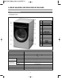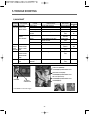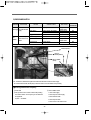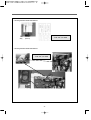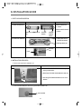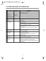
1
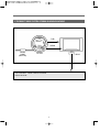
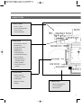
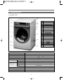
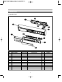
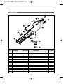
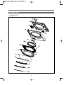
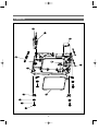
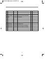
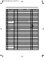
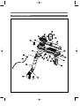
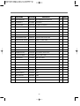
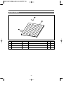
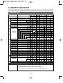
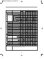
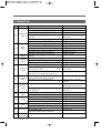
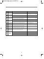
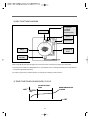
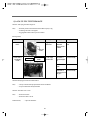
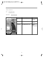
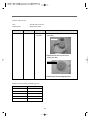
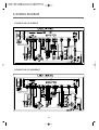
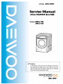
WDE115R001
DRUM WASHING MACHINE
DWD-E115R
DWD-E113R
DEC. 2006
DRUM WASHING MACHINE
SERVICE MANUAL
1. WHAT IS DRUM? ..........................................................................2
2. SPECIFICATION OF DRUM WASHING MACHINE .....................6
3. VERIFICATION OF DRUM ASSY ................................................8
4. SEQUENCE CHART OF PCB.....................................................24
5. TROUBLE SHOOTING ...............................................................34
6. WIRING DIAGRAM .....................................................................49
7. TROUBLE SHOOTING REGARDING DRAIN ............................50
8. INSTALLATION GUIDE ...............................................................51
9. ATTENTION POINT WITH SERVICING......................................53
1. WHAT IS DRUM ?
1. WHAT IS DRUM WASHER?
One of the famous washers in the globe which uses laundry falling energy.
2. Sales point of our washer
❖ The biggest capacity with compact size
❖ Environmently friendly washer with NANO technology
• Sterilizing up to 99.9%
❖ No damage and entanglement but excellent washability
❖ 4way savings-noise, vibration, washing times, energy
❖ Self-cleaning course of Drum
❖ Good washing performance with heating system
❖ Condensing dry system with saving energy
❖ Big door glass with easy laundry take-in/out
❖ The higest spin speed - 1200rpm
❖ Superior Interior Design
2
3. THE DIRECT DRIVE SYSTEM OF DRUM WASHING MACHINE
TUB
WASH
DRUM
DRAIN
PUMP
(MOTOR)
LIFTER
BLDC
• DD CONTROL : DIRECT DRIVE SYSTEM
• BLDC MOTOR
3
4. DRIVE SYSTEM
3. INLET PARTS
• COLD : 3-WAY
- COLD, PREWASH, DRY
• COLD : 2-WAY
- COLD, PREWASH
6. DRY PARTS
• HEATER DRY : OPTION
• BLOWER FAN
• FAN MOTOR : BLDC
• THERMISTOR
• THERMOSTAT
: FUSE, BI-METAL
• CONDENSING SYSTEM
• DRY FAN DRIVE
→ GENERATION OF
HEATER’S HEAT
→ TEMP. SENSOR
→ 110°C Off 100°C On :
OPTION
DRAIN PARTS
5. DOOR PARTS
• DOOR LOCK S/W
: ADDING CLOTHES
• LOCK HINGE
• DOOR AS : GLASS
• GASKET
7. DRAIN PARTS
• DRAIN PUMP(MOTOR)
• VALVE HOUSING
• DRAIN HOSE I
4
1. CONTROLLER
• MAIN PCB
• FRONT PCB
• HARNESS
• NOISE FILTER
• POWER CORD : 15A
2. DRIVE PARTS
• BLDC MOTOR
• DRUM
• BEARING
• SPIDER/SHAFT
• TUB
• WEIGHT BALANCER
4. WASH HEATING
• WASH HEATER : OPTION
• THERMISTOR
• 40°C FIXED TEMP.
CONTROL : OPTION
• 60°C, 90°C BOIL
8. SUPPORTER
• BASE
• DAMPER AS : (Right)2(60N)/(Left)1(120N)
Spring : 4
4
5. FUNCTION
2. INLET BOX AS
- INLET BOX
2. INLET BOX AS
- 3-WAY INLET VALVE
- 2-WAY INLET VALVE
- 1-WAY INLET VALVE
4. CABINET AS
7. DOCT AS
-DUCT AS
1. PANEL F ASSY
3. CABINET F ASSY
- DOOR AS
3. CABINET F ASSY
- CABINET F AS
7. DOCT AS
-DUCT AS
6. TUB ASSY
- LIFTER AS
6. TUB ASSY
5. BASE U AS
5
8. PLATE T AS
❋ 6. TUB ASSY - Parts For Driving
(6-1) BLDC ROTOR
(6-2) BLDC STATOR
(6-3) SHAFT
(6-4) BEARING
(6-5) SPIDER
(6-6) DRUM
(6-7) TUB
(6-8) BASE
BLDC MOTOR
Parts For Transmitting
(6-6)
(6-5)
6. TUB ASSY
- DRUM AS
5. BASE U AS
- PCB MAIN AS
(6-4)
(6-4)
6. TUB ASSY
- DRUM AS
(6-7)
(6-1)
(6-2)
(6-8)
5
(6-3)
2. DRUM WASHING SPECIFICATION OF MACHINE
1. EXTERIOR DIAGRAM
1 PREMIUM TYPE
16
9
12
13
NO
1
2
3
4
5
6
7
8
9
10
11
12
13
14
15
16
17
18
19
8
10
11
5
3
4
6
1
17
2
18
14
19
15
DIMENSION(WxDxH)
630mm(W) x 755mm(D) x 950mm(H)
MACHINE WEIGHT
89 kg
WATER CONSUMPTION
WASH 89
WASHING CONSUMPTION
/ DRY 28
28
POWER SOURCE
Option
POWER
WASHING
CONSUMPTION
DRY
CAPACITY
PARTS NAME
FRAME DOOR O
DOOR GLASS PLATE
DOOR GLASS BAND
HANDLE DOOR UPPER
HANDLE DOOR LOWER
HANDLE DOOR COVER
PANEL OUTER
PANEL INNER
PANEL PLATE
BUTTON DIAL OUT
BUTTON DIAL IN
CASE HANDLE
CASE HANDLE PLATE
CABINET F OUTER
COVER PUMP
PLATE T
CABINET
HANDLE CABINET
BASE UNDER
1100W (Heating ) ~ 2400W : Option
1250W ~2400W : Option
WASHING
11 kg (Domestic)
SPIN
11 kg (Domestic)
DRY
6.5 kg (Domestic)
WASHING TYPE
DRUM TYPE
DRY TYPE
OPERATION WATER PRESSURE
Digital condensing dry system
29kPa ~ 784kPa(0.3kgf/cm2~8kgf/cm2)
6
1. EXTERIOR DIAGRAM
2 LUXURY TYPE
16
7
13
12
6
10
11
8
9
NO
1
2
3
4
5
6
7
8
9
10
11
12
13
14
15
16
17
18
19
5
4
1
17
3
18
14
15
19
DIMENSION(WxDxH)
630mm(W) x 755mm(D) x 950mm(H)
MACHINE WEIGHT
89 kg
WATER CONSUMPTION
WASH 89
WASHING CONSUMPTION
/ DRY 28
28
POWER SOURCE
Option
POWER
WASHING
CONSUMPTION
DRY
CAPACITY
PARTS NAME
FRAME DOOR O
DOOR PLATE GUIDE
PROTECTOR GLASS
HANDLE DOOR UPPER
HANDLE DOOR LOWER
PANEL OUTER
PANEL INNER
BUTTON SELECT
BUTTON POWER
BUTTON DIAL OUT
BUTTON DIAL IN
CASE HANDLE
WINDOW DISPLAY
CABINET F OUTER
COVER PUMP
PLATE T
CABINET
HANDLE CABINET
BASE UNDER
1100W (Heating ) ~ 2400W : Option
1250W ~2400W : Option
WASHING
11 kg (Domestic)
SPIN
11 kg (Domestic)
DRY
6.5 kg (Domestic)
WASHING TYPE
DRUM TYPE
DRY TYPE
OPERATION WATER PRESSURE
Digital condensing dry system
29kPa ~ 784kPa(0.3kgf/cm2~8kgf/cm2)
7
3. PARTS LIST FOR EACH ASSY
1. PLATE T, PANEL LOWER AS
1 PREMIUM TYPE
No.
PARTS NAME
PARTS CODE
DESCRIPTION
A01
PANEL OUTER
3614286100
A02
HOLDER LED CUSTOM
3613052300
E110RP
1
A03
CASE PCB F
3611143600
HIPS
1
A04
PCB AS
A05
BUTTON DIAL AS
A06
HOLDER DIAL
3613052100
HIPS
1
A07
CASE HANDLE
3611143800
ABS
1
A08
CASE HANDLE PLATE
3611143900
ACRYLIC
1
A09
PANEL INNER
3614286200
ABS
1
A10
PCB AS
A11
PANEL PLATE
ABS
1
PRPSSW2D21 DWD-E110R FRONT PCB ASSY
3616634700
130RP'S BUTTON DIAL AS
PRPSSW2D22 DWD-E110R TOUCH PCB ASSY
3614286300
Q’TY
ACRYLIC
8
1
1
1
1
REMARK
1. PANEL F ASSY
2 LUXURY TYPE
No.
PARTS NAME
PARTS CODE
DESCRIPTION
Q’TY
A01
PANEL OUTER
3614286100 ABS
1
A02
HOLDER LED CUSTOM
3613052300
E110RP
1
A03
CASE PCB F
3611143600
HIPS
1
A04
PCB AS
A05
BUTTON DIAL AS
3616634700
130RP'S BUTTON DIAL AS
1
A06
HOLDER DIAL
3613052100
HIPS
1
A07
CASE HANDLE
3611143800
ABS
1
A08
PANEL INNER
3614286400
ABS
1
PRPSSW2D24 DWD-E112R FRONT PCB ASSY
1
A09
BUTTON POWER
3616635600
ABS
1
A10
BUTTON SELECT
3616635500
ABS
1
A11
WINDOW DISPLAY
3615504700
ABS
1
9
REMARK
2. INLET BOX AS
No.
PARTS NAME
PARTS CODE
DESCRIPTION
B01
INLETBOX
3617506200 PP, B110RN
1
B02
NOZZLE AS
3618104600
PP, TOP+UNDER
1
B03
CASE DETERGENT
3611143700
PP
1
B04
CAP SOFTENER
3610916600
PP
1
B05
CLAMP AS
3611203200
ID=60, WIRE+GUIDE+BOLT+NUT
2
B06
HOSE INLET
3613271000
EPDM
1
B07
HOSE A
3613266640
EPDM,ID=10,L=280MM,MAIN, B110RN
1
B08
HOSE B
3613266740
EPDM,ID=10,L=370MM,HOT, B110RN
1
B09
HOSE C
3613267040
EPDM,ID=10,L=160MM,+SHOWER, B110RN
1
B10
PIPE JOINT(HOSE INLET) 3614413300
PP
1
B11
HOSE SHOWER
3613270100
EPDM, ID=8.5, OD=12.5, GASKET SHOWER
1
B12
CLAMP HOSE
3611205800
100H, ID=13.8 W=10.0 0.9T
8
B13
VALVE INLET
3615415050
220~240V,3WAY,RINSE GUIDE, PP/BRACKET
1
B14
VALVE INLET
3615414800
220-240V 1-WAY HOT PP-BRACKET
1
10
Q’TY REMARK
3. CABINET F ASSY
1 PREMIUM TYPE
11
No.
PARTS NAME
PARTS CODE
DESCRIPTION
C01
CABINET F OUTER
3610812200
ABS
1
C02
CABINET F INNER
3610812100
SECD 0.8T
1
C03
HINGE DOOR AS
3612903500
E110R
1
C04
PLATE HINGE SUPPORT
3614539400
SPG 2.0T
1
C05
SWITCH DOOR LOCK
3619047200
DL-S1.250V16A.BITRON
1
C06
FRAME DOOR O
3612207300
ABS
1
C07
FRAME DOOR I
3612207400
ABS
1
C08
DOOR GLASS PLATE
36117ABJ00
GLASS
1
C09
DOOR GLASS
361A110600
GLASS (DWD-100DR)
1
C10
CUSHION DOOR
3611568400
DWD-E110RP
3
C11
HOOK DOOR
3613100900
ZNDC
1
C12
PIN HANDLE
3618200100
SUS, D3.0
1
C13
DOOR GLASS BAND
36117ABK00
ABS
1
C14
HANDLE DOOR COVER
3612610200
ABS
1
C15
HANDLE DOOR UPPER
3612610000
ABS
1
C16
HANDLE DOOR LOWER
3612610100
ABS
1
C17
COVER PUMP
3611427600
ABS
1
12
Q’TY
REMARK
3. CABINET F ASSY
2 LUXURY TYPE
13
No.
PARTS NAME
PARTS CODE
DESCRIPTION
C01
CABINET F OUTER
3610812200
ABS
1
C02
CABINET F INNER
3610812100
SECD 0.8T
1
C03
HINGE DOOR AS
3612903500
E110R
1
C04
PLATE HINGE SUPPORT
3614539400
SPG 2.0T
1
C05
SWITCH DOOR LOCK
3619047200
DL-S1.250V16A.BITRON
1
C06
FRAME DOOR O
3612207800
ABS
1
C07
FRAME DOOR I
3612207400
ABS
1
C08
DOOR PLATE GUIDE
36117ABL00
ABS
1
C09
PROTECTOR GLASS
3618304201
ABS TRANSPARENT
1
C10
DOOR GLASS
361A110600
GLASS (DWD-100DR)
1
C11
CUSHION DOOR
3611568400
DWD-E110RP
3
C12
HOOK DOOR
3613100900
ZNDC
1
C13
PIN HANDLE
3618200100
SUS, D3.0
1
C14
HANDLE DOOR UPPER
3612610300
ABS
1
C15
HANDLE DOOR LOWER
3612610100
ABS
1
C16
COVER PUMP
3611427600
ABS
1
14
Q’TY
REMARK
4. CABINET ASSY
15
No.
PARTS NAME
PARTS CODE
DESCRIPTION
D01
NOZZLE AIR
3618103110
PP, DWD-100DR
1
D02
FRAME TOP R
3612204300
GI, 1.6T, DWD-100DR
1
D03
FRAME TOP L
3612204900
1.6T, GI, DWD-100DR
1
D04
CABINET
3610810900
SGCD1,0.8*925.7*1922,PAINTING,DWD-110RP
1
D05
COVER BACK AS
3611425510
COVER BACK + PAD CABINET AS
1
D06
STOPPER SPRING
3615202200
POM, DWD-100DR
4
D07
FIXTURE PLATE
3612008000
130RP,POM
4
D08
FRAME UPPER
3612207600
SBHG 1.2T
1
D09
FRAME LOWER
3612207500
SBHG 1.2T
1
D10
HANDLE CABINET
3612608100
PP, DWD-100DR
4
D11
SPECIAL BOLT
3616029100
M4X12.5 MACHINE,DWD-100DR
4
16
Q’TY
REMARK
5. BASE U AS
17
No.
PARTS NAME PARTS CODE
DESCRIPTION
Q’TY
E01 CASE PCB MAIN
3611139300
HIPS
1
E02 MAIN PCB AS
3610PCBE00
E110,112R'S MAIN PCB + HARNESS AS
1
E03 UNIT FILTER(EMI K19)
3611908000
DWLF-K19,X0.47U.Y1000P.VAR471K.FUSE20A
1
E04 BASE U
3610391910
PP, DWD-100DR
1
E05 SUPPORTER LEG
3615303600
PO+ , 3.0T
4
E06 FIXTURE LEG
3612006400
ABS, DWD-100DR
4
E07 SPECIAL BOLT
3616029000
10 X 1.25, 51MM
4
E08 FOOT
3612100600
BUTYL, DWD-100DR
4
E09 ABSORBER BASE
3610115200
PE FOAM, 8X1425, 20T
1
E10 DAMPER FRICTION
361A700130
60N AKS ST=170-260 DL=197.5 LOW NOISE
2
E11 DAMPER FRICTION
361A700120
120N AKS ST=170-260 DL=197.5 LOW NOISE
1
E12 DAMPER PIN
361A700200
AKS D=14.5
3
E13 REACTOR
52G043J002
DWD-100DR, 4A
1
18
REMARK
6. TUB ASSY
19
No.
PARTS NAME
PARTS CODE
DESCRIPTION
Q’TY
F01 BALANCER WEIGHT R/L AS
3616108200
E110R
1
F02 PIPE JOINT
3614404900
PP
1
F03 CLAMP (HOSE PIPE)
3611204300
ø14, MZFN
1
F04 HOSE JOINT
3613266500
EPDM
1
F05 GASKET
3612320700
EPDM
1
F06 NOZZLE SHOWER
3618104000
PP
1
F07 CLAMP GASKET AS
3611203600
GASKET
1
F08 SPRING SUSPENSION F
3615113500
2.9
2
F09 DAMPER PIN
361A700200
AKS D=14.5
3
F10 DAMPER FRICTION
361A700130
60N AKS ST=170-260 DL=197.5 LOW NOISE
2
F11
361A700120
120N AKS ST=170-260 DL=197.5 LOW NOISE
1
F12 TUB FRONT
3618820401
FRPP FH7300GM
1
F13 DRUM FRONT
3617003101
0.5T
1
F14 DRUM CENTER
3617003001
SUS 0.5T
1
F15 DRUM REAR
3617003200
SUS
1
F16 LIFTER AS
361A400350
DWD-A11*S,LIFT BODY+FILTER AS
3
F17 SPIDER AS
361A300200
11KG
1
F18 GASKET TUB
3612321100
EPDM FORM
1
F19 DRAIN MOTOR
36196TAJ00
SV-MX7T20D 220-50/60 ST23(56.5)
1
F20 VALVE DRAIN AS
3615415100
DWD-100DR
1
F21 AIR TRAP AS
3610AAR101
110RP, HOSE+TRAP
1
F22 TUB REAR
3618820501
FRPP FH7300GM
1
F23 BEARING INNER
3616303100
6206Z FAB
1
F24 BEARING HOUSING
3616303000
ALDC
1
F25 BEARING OUTER
3616303200
6205Z FAG
1
F26 SPRING SUSPENSION R
3615113600
2.9
2
F27 HOSE AIR
3613266300
EPDM, DWD-100DR
1
F28 FIXTURE HEATER
3612007300
SUS 0.7T 440X45
1
F29 HEATER WASH
3612802400
220V 2KW.1R0A721001.RW8TF.IRCA
1
F30 UNIT BUBBLE PUMP
36189L4100
220-240V DBK-240DA 700~1200CC
1
F31 BASE
3610392000
SESEN
1
F32 UNIT STATOR BLDC
36189L4800
220V 2KW.1R0A721001.RW8TF.IRCA
1
36189L4830
ø265X28H,36SLOT,2SENSOR,3254D02000,28T AL COIL
36189L4900
MAGNET24,SERRATION,WR1238F001
F33 UNIT ROTOR BLDC
20
1
REMARK
DRUM SUB AS
7. DUCT B AS+DUCT PIPE AS
21
No.
PARTS NAME
PARTS CODE
G01
UNIT FAN MOTOR
36189L3Z00 ISM-77806DWWA 24V,CW,8P,14W
1
G02
COVER DUCT
3611426600
PBT+GF30%
1
G03
DUCT B UPPER
361A201200
ALCOSTA 0.5T*228*449
1
G04
CLAMP CORD
3611203310
DALE-3,A=12,B=4.4,L=126
4
G05
FAN AS
3611886100
D133*46L,PPGF30%,HANYU
1
G06
SCREW TAPPING
7122400811
T2S TRS 4x8
1
G07
WASHER PLAIN
7400432011
PW 4.3*20*1T
1
G08
FUSE TEMPERATURE
361A800120
128°C DF-128S 15A 250V VDE
1
G09
FRAME HEATER FRANGE 3612204100
SBHG 1.2T, DWD-100DR
1
G10
DUCT B LOWER
ALDC
1
G11
PACKING THERMOSTAT 3614009900
SILICON, DWD-100DR
1
G12
SWITCH THERMOSTAT
3619046500
ON120°C OFF150°C 230V 15A VDE
1
G13
HEATER DRY
3612800900
220V 2100W 23.05OHM 6.1W/SQ INCOLOY800 1R1A034001
1
G14
THERMISTOR DRY
361AAAAC00 R40=26.065kΩ,R90=4.4278kΩ
1
G15
PACKING RUBBER
3614009800
SILICON, DWD-100DR
1
G16
CUSHION DRY
3611562800
NBR, DWD-100DR
2
G17
GASKET SEAL A
3612320820
DWD-110RP, ø5,L=1385
1
G18
GASKET SEAL B
3612320830
EPDM FOAM, L=415, ø5
1
G19
GASKET INLET
3612322900
T=1.0
1
G20
DUCT GUIDE
361A201900
ALDC
1
G21
DUCT AS
361A200800 11KG
1
G22
CLAMP AS(DUCT)
3611203700 DUCT
2
G23
BELLOWS DUCT
3616403000 EPDM
1
G24
HOSE SPRAY(DRY)
3613266800
EPDM 470MM
1
G25
CLAMP SPRING
3611203800
ID=15.5, T=0.6, B=10
2
361A201800
DESCRIPTION
22
Q’TY REMARK
8. PLATE TOP ASSY
No.
PARTS NAME
PARTS CODE
DESCRIPTION
Q’TY REMARK
H01
PLATE T
3614539500
SECD 1.2T
1
H02
LABEL CAUTION
3613553830
DRUM 11KG,DRY+WASH,KOR,PVC,95*143,SILK 2°
1
H03
LABEL INSTALL
3613555700
ART+OPP,WATER VALVE STICKER
1
23
4. SEQUENCE CHART OF PCB
1. SEQUENCE CHART
DIVISION
Default Wash Temp
Sensing
Water Supply
Pre. Wash
Pre.
Wash
W
a
s
h
i
n
g
R
i
n
s
e
S
p
i
n
Drain
Balancing Spin
Mid.Spin
Sensing
Water Supply
Washing1
(Heating)
Drain
Balancing Spin
Mid.Spin
Water Supply
Rinse 1
Drain
Balancing Spin
Mid.Spin
Water Supply
Rinse 2
Drain
Balancing Spin
Mid.Spin
Water Supply
Rinse 3
Drain
Balancing Spin
Main Spin
Default Wash Temp
20sec
2min
10min
8min
1min
2min
3min
20sec
2min
90min
80min
65min
55min
50min
40min
35min
30min
25min
20min
1min
2min
3min
2min
3min
1min
2min
3min
2min
3min
1min
2min
3min
2min
3min
1min
2min
7min
5min
3min
60sec
10sec
Normal
Heavy Stain
Small Middle Middle
40degree
40degree
White
Small Middle
95degree
Eco-White
Small Middle
60degree
■
■
■
■
■
■
■
■
■
■
■
■
■
■
■
■
■
■
■
■
■
■
■
■
■
■
■
■
■
■
■
■
■
■
■
■
■
■
■
■
■
■
■
■
■
■
■
■
■
■
■
■
■
■
■
■
■
■
■
■
■
■
■
■
■
■
■
■
■
■
■
■
■
■
■
■
■
■
■
■
■
■
■
■
■
■
■
■
■
■
■
■
■
■
■
■
■
■
■
■
■
■
52min.
47min.
■
■
■
■
■
■
■
■
■
■
■
■
■
■
■
■
■
■
■
■
■
■
■
■
Crease care
■
■
■
■
■
■
END
■
■
■
■
■
■
Remain Time Display
1:25
1:30
1:54
2:06
2:16
1:41
NOTE
1. In the Heavy Stain Course, Prewash is included as Default.
2. Default Setting Times of Rinse in the Normal Course are two times.
3. According to Water Temperature, Wash Time is changed.
Cold - 30°C(5min)/30°C-40°C(5min)/40°C-60°C(15min)/60°C-95°C(25min)
END
24
■
■
1:51
DIVISION
Default Wash Temp
Default Wash Temp
Soak
Water Supply
W
a
s
h
i
n
g
R
i
n
s
e
S
p
i
n
Washing
Drain
Balancing Spin
Mid.Spin
Water Supply
Rinse 1
Drain
Balancing Spin
Mid.Spin
Water Supply
Rinse 2
Drain
Balancing Spin
Mid.Spin
Water Supply
Rinse 3
Drain
Balancing Spin
D
R
Y
END
NOTE
Mid.Spin
Crease care
Dry
Cooling
END
Crease care
Crease care
END
Remain Time Display
30min
2min
40min
35min
30min
25min
20min
15min
10min
8min
1min
2min
3min
2min
3min
1min
2min
3min
2min
3min
1min
2min
3min
2min
3min
1min
2min
7min
5min
3min
60sec
40min
30min
5min
10min
30min
60sec
10sec
Wool
Small
Cold
■
AntiBlanket Quick 30 Drum Drying Small Wash Memory
Allergy Middle Middle
High
Small
Cold
30°C
Cold
40°C
■
■
■
■
■
■
■
■
■
■
■
■
■
■
■
■
■
■
■
■
■
■
■
■
■
■
■
■
■
■
■
■
■
■
■
■
■
■
■
■
■
■
■
■
■
■
■
■
■
■
■
■
■
■
■
■
■
■
■
■
■
■
■
■
■
■
■
■
■
■
■
■
■
■
49
35
■
■
1:11
■
■
32
1:51
■
■
54
1. Anti-Allergy Course is for removing scent and sterilizing clothes by controlling temp.
about 70~80°C with heater dry on for 35 min.
25
DIVISION
Default Wash Temp
Default Wash Temp
Sensing
Steam Water Supply
Steam Heating
S
t
Steam Washing
e
a
m Finishing Water Supply
Finishing Washing
W
a
s
h
i
n
g
R
i
n
s
e
S
p
i
n
END
NOTE
Soak
Water Supply
Washing 2
Drain
Balancing Spin
Mid.Spin
Water Supply
Rinse 1
Drain
Balancing Spin
Mid.Spin
Water Supply
Rinse 2
Drain
Balancing Spin
Main
Crease care
END
Remain Time Display
Eco-Steam
Small
20sec
1min
20min
15min
10min
7min
1min
30min
10min
5min
30min
2min
30min
20min
15min
1min
2min
3min
2min
3min
1min
2min
3min
2min
3min
1min
2min
7min
5min
3min
60sec
10sec
Normal steam Strong Steam
Small
Middle
■
■
■
■
■
■
■
■
■
Cotton
Middle
40°C
■
■
■
■
■
■
■
■
■
■
■
■
■
■
■
■
■
■
1:27
■
■
1:30
■
■
1:35
■
■
1:30
1. Cotton Course is for all cooton clothes such as towel, diaper and the same course as
Normal Steam Course.
2. At the Steam Washing, Washing Time is 30min for Heavy Stain, and 20 min for the other
course.
3. Finishing Washing is the heating stroke to be reached up to Wash Temp, and if Wash
Temp. of Washing is 30-40°C, time is 5min, and if 60°C, time is 10min, if 95°C, time is
30min.
26
2. Main function of PCB program
2-1. LOAD SENSING
1) Deciding the water level
1 Cotton, Whites, ECO-White course will be followed by this process.
2 Check the water level with dry laundry at the starting wash.
3 Check the water level by using motor output data during 20 sec, 65 rpm.
2) Deciding Spin Starting Step.
1 Check after finishing washing step with wet laundry.
2 Checking by using motor output data during 20 sec, 65 rpm.
3 The decided data is different depending on loading condition.
2-2. BALANCE SPIN
1) Motor running during balance spin.
1 Spreading the laundry : Rotating the same 45 rpm with left and right direction alternatively.
2 Attaching stop : Attaching the laundry to drum inside with constant speed.
3 Unbalance checking point : First step, check the U.B at 95 rpm, 160 rpm.
Second step, check the U.B at 95 rpm, 350 rpm.
Third step, at 300 rpm. if the unbalance data is over the criterion,
This process will be repeated.
4 Drain step : Drain at water around 160 rpm.
5 After drain, check the unbalance data again. This is so-called balance spin step.
2) Property of balance spin.
1 Conducting 10 times maximum.
2 If the washer can not pass balance spin step during 10 times, then water will be supplied.
3 If the washer can not pass 20 times of balance spin, UE error mode will be displayed on PCB.
27
2-3. DOOR S/W
1) The working principle of Door S/W
1 Door Locking
Bimetal on ( 3 sec) --> solenoid (supply 20msec pulse 2 times)
2 Door Unlocking
Bimetal off --> solenoid (supply 20msec pulse, until unlock)
3 After door locking, all parts can work normally.
4 After pressing power button, if the temperature of wash thermistor is over 50°C or the water level is
over the safety level, the door will be locked.
6 The door will be unlocked immediately after all processes are finished.
7 The door can be opened during processing if there is no problem to unlock.
28
2) DOOR OPEN SYSTEM
1If add the laundry during washing, press the door unlock button.
2Door open sequence at abnormal condition.
start / hold
door unlock button, 2sec.ON
water level is
less than safety level?
NO
drain
YES
NO
Temperature is
less than 50°C?
YES
Display <LOCK> off
Door open
29
fan motor on/
cold water supply
2-4. Child Lock
1 Press the “TEMP”. and “DRY” button simultaneously during processing.
2 Under the Child Lock function, only power button is working.
3 During Child Lock function, CHL will be displayed on PCB.
4 In order to unlock Child Lock mode, press "TEMP" and "DRY" simultaneously.
2-5. The sequence of drain
1 If the checking time to reset point is below 1 min, the remaining drain time is 30 sec.
2 If the checking time to reset point is over 1 min, the remaining drain time is 2 min.
3 If the checking time to reset point is over 10 min, OE singal will be appeared on PCB.
4 If the temperature is over 50°C, the water will be supplied to high water level, then the drain will
start.
30
3. Convenience service functions(test mode)
1. Testing Mode
PCB and other electronic parts will be tested without water supply whether they are normal or not.
1) Process : press power button --> press "SPIN" button 3 times with pressing "WASH" button --> 'L d' will be shown on LED -> Whenever pressing "TEMP" button 1 time, below process will be occurred.
L C (Lock Closed) --> F ( Fan Motor) ---> H (Hot V/V) --> C (Cold V/V) ->
P (prewashing V/V) -> d ( dry V/V) -> bb (bubble) -> dr (drain motor) ->
L O(Lock S/W Open)
2) More details
1When turn on 'LOCK' signal, all process is conducting normaly.
2When working starts, the PCB displays all the sensor conditions.
3In this case, BLDC Motor is not tested. In order to test it, select spin or rinse.
2. Continous testing mode
1) Process : after pressing "WASH", "RINSE", "SPIN" button simultaniously, press "POWER" button.
ALL LED On/Off 1 time --> L C (Lock Closed) ---> R (Motor right) --> L (Motor Left) --> F ( Fan Motor) ---> H
(Hot V/V) --> C (Cold V/V) --> b (pre-wash V/V)
--> d ( dry V/V) --> bb (bubble) --> h1 (HEATER WASH)--> h2(HEATER DRY) --> dr (DRAIN MOTOR On) ->L O(Lock S/W Open)
2) More tails
1LED test can be done with all LED On.
2All sensor conditions will be shown on PCB during processing.
31
4. ERROR DISPLAY
MESSAGE
IE
OE
UE
LE
E2
E3
E4
E5
E6
E7
E8
E9
ERROR
CAUSE
SOLUTION
The water tap is closed.
Open the water tap.
The filter of the valve inlet is clogged.
Clean the filter of the valve inlet.
The valve inlet is an inferior product or broke down.
Change the valve inlet.
WATER INLET
The water level sensor (sensor pressure) is an inferior product or Change the water level sensor
ERROR
broke down.
(sensor pressure).
The drain motor works during water supply.
Change the drain motor.
The PCB ASS’Y does not check the water level.
Change the PCB ASS’Y.
The drain hose is kinked or clogged.
Clean and straighten the drain hose.
The drain motor is an inferior product.
Change the drain motor.
DRAIN
The valve inlet works during drain.
Change the valve inlet
ERROR
The water level sensor is an inferior product .
Change the water level sensor.
The PCB ASS’Y does not check the water level.
Change the PCB ASS’Y.
Rearrange the laundry.
UN-BALANCE The laundry is concentrated to one side of the drum
ERROR
during spin.
The Start/Hold button is pressed while the door is opened.
Close the door.
DOOR OPEN
The switch door lock is an inferior product.
Change the switch door lock.
ERROR
The PCB ASS’Y does not check the door lock.
Change the PCB ASS’Y.
The water is supplied continuously due to an inferior valve inlet. Change the valve inlet.
The valve inlet is normal, but the water level sensor
Change the water level sensor
OVERFLOW
(sensor pressure) is inferior.
(sensor pressure).
ERROR
The drain motor dose not work.
Change the drain motor.
(The drain motor is an inferior product or broke down.)
The fan motor does not work.
Change the fan motor.
FAN MOTOR (The fan motor is an inferior product or broke down.)
ERROR
The PCB ASS’Y does not control the fan motor.
Check the connector or change the
PCB ASS’Y .
Water leaks from the tub or the hose drain.
Check the leak of the tub or the hose drain.
Then change the tub or the hose drain.
LEAKAGE
ERROR
The foreign matter is jammed in the drain bellows.
Remove the foreign matter in the
(Non-pump model)
drain bellows.
Rearrange the laundry.
HIGH VOLTAGE The laundry is jammed between the gasket and the drum.
ERROR
The PCB ASS’Y is an inferior product.
Change the PCB ASS’Y.
The laundry is jammed between the gasket and the drum.
Rearrange the laundry.
EMG ERROR The motor is an inferior product.
Change the motor.
The PCB ASS’Y is an inferior product.
Change the PCB ASS’Y.
The motor spins into an opposite direction.
Change the PCB ASS’Y or the motor.
DIRECTION
ERROR
The motor hall IC is an inferior product or broke down.
Change the motor hall IC or the motor.
The motor is not normally connected.
Check the connector of the motor.
MOTOR ERROR The motor does not work.
Change the motor.
(The motor is an inferior product or broke down.)
SENSOR
The water level sensor is an inferior product.
Change the water level sensor.
PRESSURE ERROR
32
MESSAGE
H1
H2
H3
H4
H5
H6
H7
H8
PFE
ERROR
CAUSE
THERMISTOR The thermistor dry is an inferior product or broke down.
(TEMP. SENSOR) The thermistor dry is not connected normally.
DRY ERROR
SOLUTION
Change the thermistor dry.
Check the connector of the thermistor dry.
The thermistor wash is an inferior product or broke down.
The thermistor wash is not connected normally.
THERMISTOR DRY The fan motor does not spin with the proper rpm.
OVERHEATING (The fan motor is an inferior product or broke down.)
ERROR
The thermistor dry is an inferior product or broke down.
THERMISTOR WASH The heater worked without the water in the tub.
OVERHEATING The thermistor wash is an inferior product or broke down.
ERROR
Change the thermistor wash.
Check the connector of the thermistor wash.
Change the fan motor.
THERMISTOR
WASH ERROR
WATER TEMP.
ERROR
The water temp. is over 45°C in delicate & wool course.
HEATER WASH The heater wash dose not work.
ERROR
(The water temp. doesn't rise over 2°C during 15min.)
HEATER DRY The heater dry dose not work.
ERROR
(The water temp. doesn't rise over 3°C during 8min.)
HEATER WASH
OVERHEATING The heater worked without the water in the tub.
ERROR
PUMP
FILTER
ERROR
The drain pump filter is clogged.
The drain pump does not work during spin.
The large amount of detergent was used.
The drain hose is placed higher than 1m above the floor.
33
Change the thermistor dry.
Check the water level.
Change the thermistor wash.
Change the thermistor wash.
Change the heater wash.
Change the heater dry.
Check the water level and the heater wash.
Clean the drain pump filter.
Change the drain pump.
Use the proper amount of detergent.
Place the drain hose 1m below the floor
5. TROUBLE SHOOTING
1) VALVE INLET
TROUBLE
SITUATION
WATER IS NO WATER
SUPPLIED SUPPLY WITH
"BUZZ" SOUND
NO WATER
SUPPLY
WITH SILENCE
CAUSE
CHECK POINT
closed water tap
coil short
alien materal jammed
alien material inside
inlet valve
unfixing connector
check the water tap opened
check the resistance 4320~5280Ω
check the filter
coil short
check the resistance 4320~5280Ω
check the connector
check the pressure switch
check the hose torn or twisted
harness short
pressure s/w broken
THE WATER
SUPPLY START
pressure hose broken
WHEN POWER
"ON"
inlet valve broken
THE WATER
SUPPLY START
WHEN POWER
"OFF"
water leakage to the inlet valve poorly
Etc
assembled
side
Checking method of coil resistance, harness, connector.
WATER
SUPPLY
IS NOT
STOPPED
–
check the connector
–
check the leakage of inlet valve
PCB
ERROR MODE
Open the water tap
"IE"
"IE"
Clean the filter
"IE"
Change the InletValve
"IE"
The contact of the
"IE"
Connector
Change the Inlet"IE"
Valve
"IE"
Change the Sensor
Pressure
"E2"
Change the bad
"E2"
parts
Change the InletValve
SOLUTION
Change the InletValve
WASH VALVE(GREEN) :
COMMON(BLUE)/RESISTANCE TEST
PRE-WASH VALVE(RED) :
COMMON(BLUE)/RESISTANCE TEST
DRY VALVE(YELLOW) :
COMMON(BLUE)/RESISTANCE TEST
MAIN PCB
"8P" WHITE
CONNECTOR
COMMON(BLUE)
* "IE" ERROR : lack of water supply
34
-
2) PRESSURE SWITCH
TROUBLE
SITUATION
continuously inlet valve is normal,
water supply but continuous water
supply
"E9"
ERROR
water level frequence
below 15kHz or over
30kHz
CAUSE
CHECK POINT
SOLUTION
bellows problem
frequency Check : refer to below
hose problem
clogged hose
connector slipped out
pressure switch broken
frequency Check : refer to below
check the fine hole
check the hose condition
check the connector condition
frequency Check : refer to below
connector short
connector broken
change the
pressure switch
change the hose
change the hose
remove the alien
reconnecting
change the
pressure switch
PCB
ERROR MODE
"E2"
"E9"
Checking method of coil registance, harness, connector.
GROUND(GRAY)
OUTPUT
SIGNAL(WHITE)
INPUT SIGNAL
(PINK)
"12P" WHITE CONNECTOR
* E2 : overflow error ;Water level is higher than overflow level because of continuous water supply.
E9 : Pressure switch trouble, the frequency is less than 15kHz or more than 30kHz in the processing.
■ Checking method of the Frequency
1 Power ON
3 Press “TEMP” button
2 First, press the “DRY” button 3 times with pressing
1 time: water supply
the “WASH” button. The frequency of Air status will
2 times: stop the water supply
be appeared.
3 times: start the drain
ex) 623 ➝ 26.23kHz.
4 times: stop the drain
5 times: return to Air status mode
35
"E2"
"E2"
"E2"
"E9"
"E9"
3) DOOR LOCK SWITCH
1) CLASS
Failure
Status
"Tick"
Sound
"LE" Error
Details
Tick Sound happens
"LE" with tick sound
"LE" without tick sound
DOOR not Power Failure/Forced
Power Off during
open
operation
Power on state
ETC
PCB
ERROR MODE
When Door is locked/unlocked, this Solenoid Working
Normal Sound
sound is heard.
check the joining status of
Assemble Connector
Connector slipped out
"LE"
connector by eye
Close Door securely
DOOR closed loosely
"LE"
Replace DOOR AS
Failure of DOOR HOOK "LE"
Tick sound happen
CATCH CAM broken
"LE"
Replace DOOR S/W
check the joining status of
Connector slipped out
"LE"
Assemble Connector
connector by eye
Refer to below checking
Terminal slipped out
"LE"
Insert Receptacle no.2
method.
or no.3
Refer to below checking
Solenoid Coil
"LE"
Replace DOOR S/W
method.
Disconnection
During operation, "Power Failure" or "Forced Power S/W OFF" causes door not to be opened until
maximum 5 minutes pass.
Cause
Water remained in tub
hot temp. in tub
Follow below process
Diagnosis of Failure
Solution
Check whether the water
After draining water,
level is over safety level.
open the door
Prevent the burn due to hot temp. after dry.
-
Checking Method of wiring/coil disconnection, connector slipping out on PCB board : Operate with the Door lock
switch connected
1. Replacing method of DOOR LOCK SWITCH
1) Open DOOR, disassemble CLAMP SPRING for fixing gasket
2) Disassemble GASKET
3) Disassemble two screws for DOOR LOCK S/W
4) Disassemble DOOR LOCK S/W
5) Assemble in the reverse order
36
2. Checking method of DOOR LOCK SWITCH
PIN
2345
array
(No no.1)
Between No. 3 & No.4
: if 156 ~ 234Ω, it is normal
3. Checking method of DOOR LOCK SWITCH
Between Viloet and Blue wire
: If 156 ~ 234Ω, it is normal
37
4) HEATER
Failure
Cause
Status
Can not Wiring Disconnection
heat
Heater Wash
water
Disconnection
Connector/Terminal
Seclusion
Heater Wash/Thermistor
Wash Poor
Overheat Heater Wash/Thermistor
Wash Poor
water
Can not Wiring Disconnection
dry
Heater Dry Disconnection
Fuse Temp.
Diagnosis of Failure
Check whether disconnected or not : See Fig. A
Check whether disconnected or not : if normal, the
resistance between two ends is 23.3~25.7Ω.
Check whether disconnected or not : See Fig. A
Measure the resistance of two ends of the sensor : if
11.981KΩat R25, it is mormal
Measure the resistance of two ends of the sensor : if
11.981KΩat R25, it is mormal
Check whether disconnected or not : See Fig. B
Check whether disconnected or not : if normal, the
resistance between two ends is 22.3~24.7Ω.
Shipped out
Connector/Terminal
Slipped out
Check whether disconnected or not : See Fig. B
Operation Trouble of FAN
MOTOR
Excessive Noise : Restraint/Failure of Fan Motor
Heater Wash/Thermistor
Fault of Thermistor (Dry)
Fan slipped out : MOTOR is operating, but there is
rotating sound.
Measure the resistance of two ends of the sensor : if
26.065KΩ, it is mormal
PCB
Error Mode
Solution
Connecting the
disconnecting point
Replacing Heater Wash
"H6"
terminal/connector tightly
Connecting
Replacing temp. sensor
"H6"
Replacing Heater Wash
"H2" or "H4"
Inserting terminal/connector
"H7"
Replacing Fuse Temp.
"H7"
tightly
Connecting
Re-connecting
"H7"
"H6"
"H2"
"H7"
Replacing Fan motor
"H7" or "E3"
Re-assemble after
disassembling
Replace Thermistor
"H7"
"H1"
Checking Method of wiring/coil disconnection, connector slipping out on PCB board : Operate with the heater connected
[Figure A]
* Inspect Wiring/Heater
Wash Disconnection :
Check the current and
resistance of two
terminals
[Figure B]
* Inspect
Wiring/Heater Dry
Disconnection :
Check the current
and resistance of two
terminals
3P Connector
orange wire
3P Connector
Red Wire
1P Connector
Blue Wire
1P Connecor
Blue Wire
38
* Replaceing method of Heater and Temp. Sensor
1. Disassemble Connector
2. Disassemble EARTH and NUT for fixing heater
3. Replace heater & sensor
4. Assemble in the reverse order. Be sure to assemble in the
order : Nut for heater-Nut for EARTH.
C
I
Division
D
H
E
F
B
A
Parts Name
A
DUCT COVER
B
FAN MOTOR
C
HEATER DRY
D
DUCT B LOWER
E
THERMOSTAT(Bimetal)
F
THERMISTOR (Temperature Sensor)
G
DUCT B UPPER
H
FAN AS
I
FUSE TEMPERATURE
G
* ERROR MODE
1. "H1" : Thermistor Dry OPEN/SHORT
2. "H2" : Thermister Wash OPEN/SHORT
3. "H3" : Dry Overheating(Sensing Temp. is over 125°C)
4. "H4" : Wash Overheating(Sensing Temp. is over 95°C)
5. "H5" : Wash Overheating
(In Wool, Lingerie courses sensing temp. is over 45°C)
6. "H6" : Abnormal condition of Heater Wash
(when the temp. increase at 10 minutes after heater operation is under 10°C)
7. "H7" : Abnormal condition of Heater Dry(when the temp. increase at 10 minutes after heater operation is under 10°C)
8. "H8" : Heater Wash Overheating
(when the temp. increase within 30sec after heater operation is over 5°C without water)
9. "E3" : FAN MOTOR Broken(no signal from HALL IC)
39
5) MOTOR
1) BLDC MOTOR
Rotor
Insulator
Core
Insulator
BLDC MOTOR
2) Driving mechanism of BLDC MOTOR
Magnetic density flow of BLDC Motor
Sequence diagram of BLDC MOTOR
electromagnet
generating high power by rotator
(a permanent magnet) and stator
(multiple coils)
40
6) DRY SYSTEM(OPTION)
1) DRY SYSTEM
E
C
J
D
I
F
G
B
A
H
41
Division
Parts Name
A
DUCT COVER
B
FAN MOTOR
C
HEATER DRY
D
DUCT B LOWER
E
VALVE INLET(DRY)
F
THERMOSTAT(Bimetal)
G
THERMISTOR(Temperature Sensor)
H
DUCT B UPPER
I
FAN AS
J
FUSE TEMPERATURE
2) DRY FUNCTION DIAGRAM
T : Thermistor
(CONTROL
HEATER’S
TEMPERATURE )
DRY DUCT
HEATER
T
FAN MOTOR
WATER SUPPLY
CONDENSING
DUCT
DRUM
DRAIN
HOUSING
While rotating DRUM, DRY HEATER applice heat to air and FAN blows it into DRUM evaporating water in the laundry.
• Evaporated water is sucked into CONDENSING DUCT, and condensed in DUCT contacting WATER SUPPLY (condensed water
is extracted through DRAIN HOUSING).
• Dry function is performed by continuous repetition of evaporating and condensing circulation as above.
3) TEMP-TIME GRAPH DURING DRY CYCLE
DRYING PROCESS
ZONE
건조진행구간
TEMP.
온도
INSIDE
TEMPERATURE
DRUM
OF DRUM
내부온도
PRE예열
HEATING
ZONE
구간
TIME
시간
42
4) DRY COURSE
COURSE
LOW TEMP.
IRON
Cupboard
STRONG
SELECTING TIME
1Hr, 2Hr, 3Hr.
DRY COURSE
Heater control temperature is 60°C On/70°C Off
Drying Time is 120/180min according to Load Sensing Data
Heater control temperature is 60°C On/70°C Off, with good condition for ironing
Drying Time is 70/130min according to Load Sensing Data
Heater control temperature is 100°C On/110°C Off, drying time is 166 min
Drying Time is 150/210min according to Load Sensing Data
Heater control temperature is 100°C On/110°C Off, drying time is 216 min
Drying Time is 210/270min according to Load Sensing Data
Heater control temperature is 100°C On/110°C Off, customer can select the drying time
out of 1:00, 2:00, 3:00
In order to check the drying temperature during process going on : --> press the "DRY" button, the display shows as below.
UPPER LED:
Temperature for DRY
REMAIN TIME
남은시간
The current temperature is 98°C
LOWER LED:
Temperature for WASH
43
5) TROUBLE SHOOTING OF DRY SYSTEM
✦ HEATER DRY
Function : heating the air during dry
• FAILURE MODE : * "H7" - The air cannot be heated to 10°C during 2 min.
• CHECKING METHOD : * Check the resistance of heater coil and replace with new one.
✦ Thermistor
Function : sensing the air temperature.
• FAILURE MODE : * The air cannot be heated even though water is supplied.
* "H1" - shot or cut-off
* "H3" - air temp. is reached over 150°C
• CHECKING METHOD : * Check the resistance of thermistor, replace with new one.
✦ FUSE TEMPERATURE
function : protecting from the fire hazard or overheating, if the temp., rises over 128°C, power supply will be cut-off.
• Pictures
FIXED BY
WASHER
+SCREW
• FAILURE MODE : Dry is not performed.
• CHECKING METHOD : Check if fuse is short, and replace with new one.
44
✦ SWITCH THERMOSTAT(BIMETAL)
function : control the duct temperature, if the temp reached over 150°C, all power supply will be cut. and if the temp go down
120°C the power will be ON.
protecting overheating by cutting off heater power supply if the temperature rises over 150°C, and reoperating heater
by connecting heater power supply if the temperature falls under 120°C.
• OPERATING TEMPERATURE
• PICTURE
OPEN TEMPERATURE(OFF)
150°C ± 5°C
CLOSE TEMPERATURE(ON)
120°C ± 5°C
✦ UNIT FAN MOTOR
function : circulating the inside air during dry process.
• SPEC
• PICTURE
ITEMS
SPEC
RATING VOLTAGE
24V
RPM
MOTOR
3700 ± 10%
DUCT FAN AS
1900 ± 10%
ROTAING DIRECTION
CW
• FAILURE MODE : * E3 shown : FAN MOTOR cannot work.
• CHECKING METHOD : Check the FAN MOTOR is short, and replace with new one.
45
6) LACK OF DRY PERFORMANCE
• Situation : after drying, the clothes still get wet.
cause)
☞The laurdry amount is more than the recommendation capacity 7.0kg.
☞Condensing cold water is not supplied.
☞Clogging Bellows Duct results in poor air circulation.
checking method)
part name
checking point
checking results
BELLOWS
DUCT
VALVE INLET
CONDENSING
HOSE
repair method
clogging
bellows duct
heater was
overheated
owing to poor air
circulation
clean the bellow
duct
no water supply
from inlet valve
VALVE INLET
connector slipped
out
connect normally
VALVE INLET
broken
replace valve inlet
BELLOW
DUCT
VALVE INLET
+Condensing
HOSE
jurge
ill-connection of
connect normally
condensing hose to
duct pipe
• Situation after drying, the clothes was soaked and hot.
cause)
☞ The dry is done from bad spin performance because of unbalance.
☞no spin was done before the dry had started.
• Situation : PCB shows "H1" or "H3".
cause)
☞Thermistor is broken.
☞Thermistor is short or cut-off.
countermeasures)
☞replace the Thermistor.
46
• Situation : PCB shows "H7".
cause)
☛ Dry heater is cut-off.
☛ Fuse temp. is cut-off.
repaire method)
☛ replace the Dry heater.
☛ replace the Fuse temp.
checking point
part name
HEATER
FUSE
TEMPERATURE
checking results
repaire method
dry Heater is short or cut-off.
replace the
dry Heater.
SENSOR TEMP. Thermistor is short or cut-off.
replace the
Thermistor.
FUSE TEMP.
FUSE TEMPERATURE is cut-off.
HEATER DRY
THERMISTOR
47
replace the
FUSE
TEMPERATURE.
• situation : PCB shows "E3".
☞FAN MOTOR can not work.
☞Replace the Fan Motor.
cause)
countermeasures)
part name
checking results
repair method
FAN MOTOR
fan motor failure
replace
fan motor
disassemble process of Fan Motor
1Disassemble Duct Cover As from Duct B As
(Screw 4EA)
DUCT COVER AS
2Disassemble FAN AS From Duct Cover As
(Fixed by 8mm NUT)
Fixed By 8mm NUT
3Disassemble the FAN MOTOR(SCREW 3EA)
Remarks) control times of each parts during dry process
parts
Control time
MOTOR
10 sec On, 10sec Off
DRAIN MOTOR
Continous working
FAN MOTOR
Continous working
DRY HEATER
100°C On, 110°C Off
INLET VALVE
5sec On, 20sec Off
48
6. WIRING DIAGRAM
DOUBLE VALVE, BUBBLE
(OPTION)
(OPTION)
DRAIN PUMP
Or
DRAIN MOTOR
DOUBLE VALVE, N/BUBBLE
(OPTION)
(OPTION)
DRAIN PUMP
Or
DRAIN MOTOR
49
7. TROUBLE SHOOTING REGARDING DRAIN
❑ Checking Methods
• Situation :
* "OE" is shown on PCB.
* Not finishing drain during 10 min.
* The water level can not reach to RESET POINT during 10 min of drain.
Checking Methods
Replacing methods
* Check the hose drain O condition; twisted or frozen.
* replace HOSE DRAIN O
* Check the hose drain O condition, blocked.
* clean the inside of Filter.
* DRAIN MOTOR is broken.
* replace DRAIN MOTOR
50
8. INSTALLATION GUIDE
1. PARTS & CONFIGURATION
FIGURES
PARTS NAME
REMARKS
FIXTURE UP/DOWN AS
SPECIAL SCREW UP
: L= 109mm
SPECIAL SCREW DOWN
:L=145mm
SPECIAL SCREW
FIXTURE UP
UP
FIXTURE
DOWN
SPECIAL
SCREW
DOWN
1Use this part to remove
FIXTURE UP/ DOWN.
UNIT SERVICE WRENCH
2Adjust leg with this part.
LEG ADJUST AS
FIXTURE
LEG
FOOT
2. INSTALLATION PROCESS
1Remove the FIXTURE UP/DOWN AS
Removal Method
Remarks
☞ Disassemble the FIXTURE UP/DOWN AS by
turning CCW direction.
☞ Please keep FIXTURE UP/DOWN AS for later use.
☞ When fixing FIXTURE UP/DOWN AS, turn it CW
direction.
2Insert CAP HOLDER(4EA) after removing FIXTURE UP/DOWN AS.
CAP HOLDER
51
3Please install the DRUM WASHING MACHINE properly on even and hard floor as below.
4Adjust the level of washer using LEG ADJUST AS.
Adjusting Method
Remarks
☞ If turned CW, the LEG ADJUST AS moves the
washer upward.
☞ If turned CCW, the LEG ADJUST AS moves the
washer downward.
5After adjusting level, fix SPECIAL BOLT.
Adjusting Method
Remarks
✰ Please fix the SPECIAL BOLT by rotating it CCW
in order to prevent washer vibration.
52
9. ATTENTION POINT WITH SERVICING
No
Item
1 Replacing Thermistor
Dry
2 Replacing Duct B As
& Duct Pipe
3 Replacing &
Repairing Inlet Valve
4 Replacing Hose Drain
5 Replacing HOSE
A,B,C
6 Replacing
Heater Wash
Part Name
Thermistor Dry
DUCT B AS &
DUCT PIPE
Inlet Valve
Hose Drain
HOSE A,B,C
Heater Wash
7 Replacing
“Thermistor Wash”
8 Assembling
“Hinge Door”
Thermistor Wash
9 (Dis)assembling
“Door AS”
10 (Dis)assembling
“Motor AS”
Door As
Hinge Door
MOTOR AS
Checking Point
Keep the Packing from seperating (Hold Packing when replacing)
Keep the Packing from folding
Check the sealing between Duct Pipe & Duct B AS
Use only screw M4*8 for fixing Inlet Valve
Keep the sealing condition of Tub O tightly
Check the assembling order between INLET BOX & Hose A,C :
Pre Wash-Cold
Unfastening the nut for fixing earth first then unfasten
the nut for fixing heater
At assembling the heater dry, check if the assembling condition between
fixture heater is tight.(little gap on left & right)
At fastening the nut for fixing the heater wash, keep the protrusion length
of bolt to 10~12mm.
(if under 10mm, water can leak, and if over 12mm, fixture heater can
deform)
Unfasten the Nut for fixing heater, replace the thermistor, and
fasten the nut for fixing heater
At fastening screw for fixing Door AS, be careful so that scratching at
the related parts does not happen
: If the scratching happens, it is possible to be claimed about
appearance damage
Be careful about the up/down direction of Door Glass : Keep the
indication point of the part code downward.
To avoid the injury on the hand, grip the rim of the rotor
At initiating the assembling operation of the stator, grip the
stator and fasten the screw; at unfastening the screw, grip the stator so
that it does not fall.
53
DAEWOO ELECTRONICS CORP.
686, AHYEON-DONG MAPO-GU SEOUL, KOREA
C.P.O. BOX 8003 SEOUL, KOREA
TELEX: DWELEC K28177-8
CABLE: “DAEWOOELEC”
DRUM WASHING MACHINE
2006. 12