1
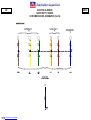
Body Builders Layout Book
1
ELECTRICAL WIRING
ELECTRICAL WIRING
ELECTRICAL WIRING
INDEX
Page
Customer Access Circuits – General Information
2
General Practices – Addition of Lights or Electrical Devices
3-5
E-Series
Chassis Circuits
6
Upfitter Switches
7
Customer Access Circuits
8-10
Stripped Chassis
11
Stripped Chassis – Rear Frame
12
Trailer Tow Wiring
13-15
Dual Battery Schematics
16-17
Customer Access Schematics
18-24
Super Duty F-Series
Customer Access Schematics
www.fleet.ford.com/truckbbas
25-30
2014
MODEL YEAR
Body Builders Layout Book
2
ELECTRICAL WIRING
ELECTRICAL WIRING GENERAL INFORMATION
Super Duty F-Series and selected E-Series Super Duty
vehicles are equipped with a number of conveniently
located electrical wiring taps. Most taps are fused,
having locations under the instrument panel, in the
engine compartment, and at the rear of the frame.
Illustrations, schematics and a wiring harness for Trailer
Tow is provided in a cardboard box shipped with each
vehicle. The circuits at the rear of the frame are
provided to support trailer wiring requirements or the
Second Unit Body (SUB) additions. The E-Series and
Super Duty F-Series Circuit charts have a brief
description of each circuit function, wire gauge, color
code and electrical schematic.
1. The Ford starting and the charging system should
not be altered.
2. The completed vehicle total electrical load must not
exceed the maximum output of the alternator.
3. Do not route or attach electrical wires to fuel lines.
4. Engine compartment wiring must not be rerouted in
any manner.
5. The 6.4L diesel engine requires two batteries wired
in parallel for proper starting operation and must not
be isolated. Do not modify the Glow Plugs Power
Circuits.
ELECTRICAL WIRING
GENERAL PRACTICES
ADDITION OF LIGHTS OR ELECTRICAL DEVICES
6. Ford recommends that all additional underhood and
underbody wiring:
● Be cross-linked polyethylene, or equivalent, high
temperature insulation wire 125° C [257° F]
minimum rating.
● Meet SAE specifications J1128 type SXL, GXL or
TXL.
● Meet SAE J1127 type SGX or STX for battery
cables.
● Be protected with nylon convoluted tubing.
● Be located so as to avoid or minimize restriction of
airflow through the engine compartment,
underbody and fuel system.
● Be of sufficient length to be properly routed, so as
not to interfere with operating zones of such
components as throttle or transmission linkage.
● Not be routed near the exhaust system or any
other source of high heat; melted insulation can
result in electrical shorts and system failure.
● Be routed away from hostile surfaces and sharp
edges and be secured in its intended location.
● Be protected by rubber grommets when it passes
through body or frame openings. Use customer
access pass-thru circuits provided on Super Duty
F-Series to avoid additional openings between
passenger and engine compartments.
● Be protected from electrical shorts by fuses or
circuit breakers.
● Be routed at least 38 mm [1.5 in] away from
engine.
7. Interior wiring not exposed to high temperatures
may be SAE approved, general purpose wire.
8. Ground the second unit body to the frame in at least
two locations, and if required, add an additional
frame to engine ground cable to improve the ground
path to the battery.
9. Splicing into circuitry relating to the powertrain
control systems is not acceptable because of the
adverse effect on the electrical system operation.
10. Batteries must be disconnected before welding to
body and chassis components. Note that
disconnecting the batteries will result in a memory
loss on electronic engine/transmission controlled
vehicles. The vehicle will require several miles of
driving in various driving modes to restore its
memory and regain optimum operating conditions.
11. Electrical connections exposed to the elements
should be appropriately protected.
12. Do not ground the body to the transmission or
transmission crossmember.
13. Ignition circuit of any engine should not be altered.
14. Alternator circuit wiring must not be altered by
cutting, soldering or splicing.
15. Some head lamps are plastic and have protective
coatings which can be damaged by solvents or
tape. Refer to the Owner’s Guide for proper
cleaning procedures.
16. For convenience, Super Duty F-Series has (4) 14
gage blunt-cut pass-thru circuits located in the cabin
within a bundle above the parking brake pedal and
found in the engine compartment in a harness
below the cowl, just outboard of the brake master
cylinder. E-Series also has (2) 12 gage pass-thru
circuits located in the cabin above the driver-side
kick-panel in a 6-pin connector (F7UB-14A41-B)
and found in the engine compartment at the 4-pin
connector (F4UB-14A411-A) in a harness below the
cowl, outboard of the brake master cylinder. These
circuits provide an unfused means to interface
wiring between the cabin and the engine
compartment without drilling through the dash
panel. See the Customer Access Circuits charts for
further information regarding pass-thru circuits.
2014
MODEL YEAR
17. Center High Mounted Stop Lamp (CHMSL) wiring
taps are provided on E-Series Super Duty
Cutaway/Stripped Chassis and Super Duty F-Series
Chassis Cab vehicles.
18. Electrical bulbs are listed in the Owner’s Manual
Bulb Chart. Check for the “DOT” marking on the
bulb base which means the bulb meets U.S. “DOT”
standards. Bulbs without the “DOT” marking or that
produce different colors other than the original bulbs
as listed in the bulb chart, may affect the lamps light
output, aim, glare and your safety; in addition, such
bulbs may burn out early or damage the lamp.
19. Super Duty F-Series vehicles are equipped with a
clean tachometer output (CTO) wiring tap. The tap
is designated circuit CE913 (BU) and is located
under dash near the parking brake pedal. This tap
should be used if a tachometer signal is required.
The signal is digital and requires a digital
tachometer. The signal pulse rate is half the number
of engine cylinders per revolution (i.e., 4 for 5.4L
gasoline and 6.4L diesel, 5 for 6.8L gasoline). ESeries vehicles are also equipped with CTO wiring
tap. The tap is designated circuit CE913 BU and is
located under hood near the PCM connector.
20. Super Duty F-Series & E-Series vehicles are also
equipped with a vehicle speed out (VSO). The VSO
tap is designated circuit VMC05 (VT/OG). The tap is
located under dash near the parking brake pedal.
The VSO tap signal frequency is 2.22 times the
vehicle speed in miles per hour.
Additional Electrical information
can be accessed via the web at:
www.fleet.ford.com/truckbbas
under the “Bulletins” tab.
(Cont'd next page)
www.fleet.ford.com/truckbbas
Body Builders Layout Book
3
ELECTRICAL WIRING
This section provides instructions for the addition
of electrical devices to the vehicle electrical system
by body builders.
Vehicles stored on site should have the negative
battery cable disconnected to minimize a “Dead
Battery”
situation.
This
applies
to
both
“incomplete” and “complete” vehicles in storage.
After all electrical or vehicle modifications, perform onboard diagnostics to the Body Control Module (BCM).
Road test vehicle and re-run the on-board diagnostics
to verify that no DTCs are present. If DTCs are
generated perform the appropriate diagnostic
procedures and repairs. Vehicle operation (engine,
transmission and vehicle lighting) may be affected if
DTCs are not serviced.
F/CMVSS, U.S. and Canadian RFI Requirements
1. All Ford vehicles built and fully completed by Ford
comply with F/CMVSS No. 108, “Lamps, Reflective
Devices and Associated Equipment” and other
applicable
F/CMVSS
that
affect
electrical
components. Care must be taken that modifications
do not conceal, alter or change components installed
or provided by Ford Motor Company to achieve this
conformance.
2. Incomplete vehicles (i.e., Chassis Cab, Stripped
Chassis, etc.) will conform to the F/CMVSS
according to the provisions and conditions stated in
the Incomplete Vehicle Manual (IVM) attached to
each incomplete vehicle.
3. Devices that emit radio frequency (RF) energy, such
as AM/FM radios and radio-controlled security
systems, marketed for sale or use in the United
States are subject to the rules and regulations of the
Federal Communications Commission (FCC) 47
CFR Parts 2 and 15.
These rules specify the following conditions of
operation:
This device complies with Part 15 of the FCC
Rules. Operation is subject to the following two
conditions:
(1) This device may not cause harmful interference,
and
(2) this device must accept any interference
received, including interference that may cause
undesired operation.
In addition, the FCC’s Rules may require the device
to be tested and found to comply with various RF
interference emission limits before it may be
marketed. The FCC establishes different limits
according to the particular use and installation of RF
devices. In some cases, a grant of equipment
authorization from the FCC also must be obtained
before any RF device may be marketed. Labeling
with certain FCC information may also be required.
www.fleet.ford.com/truckbbas
2014
ELECTRICAL WIRING
GENERAL PRACTICES
ADDITION OF LIGHTS OR ELECTRICAL DEVICES
To ensure continued compliance with the FCC’s
requirements, the owner, user, custom manufacturer,
or service technician must not modify or change the
RF device in a manner not expressly approved by
Ford Motor Company. Such modifications could void
the authority to operate the device.
4. All vehicles powered by spark ignition internal
combustion engines (e.g., gasoline or liquid
petroleum gas engines) and manufactured in
Canada or for sale or use in Canada are subject to
the Canadian “Regulations for the Control of
Interference to Radio Reception” per InterferenceCausing Equipment Standard (ICES-002) and
applicable test method according to “CAN/CSAC108.4-M06”. Violation of these regulations is
punishable by fine or imprisonment. Ford-built
incomplete vehicles other than stripped chassis are
designed and manufactured to be capable of
meeting the regulatory requirements or such
modifications thereof as may be authorized by the
Canadian Department of Communications. However,
because Ford has no control over how an
incomplete vehicle is completed by subsequent
stage manufacturers, Ford does not represent that
the completed vehicle incorporating the Ford-built
components
will
comply
with
applicable
requirements.
Routing & Clipping
1. It is strongly recommended that wiring in areas of
heavy rework, or in areas where welding operations
are to be performed, be removed prior to the rework
operations and reinstalled after the rework is
completed. The Instrument Panel (IP) cluster, Power
Control Module (PCM) and Body Control Module
(BCM) must be disconnected before any electrical
welding is performed, otherwise module damage
may result. If wire removal is not practical, the wires
must be shielded from damage due to the rework
and welding heat. All components and wiring should
be reinstalled as closely as possible to the way it
was installed before removal.
2. Wire routings of newly installed components or wire
routing revisions of the Ford harnesses necessitated
by reworks must conform to the following:
● Wires
routed through holes in sheet metal or
castings must have the hole edges protected by a
grommet.
● Wires should be routed to avoid metal edges,
screws, trim fasteners and abrasive surfaces.
When such routings are not possible, protective
devices (shields, caps, etc.) must be used to
protect the wires and when wires must cross a
metal edge the edge should be covered with a
protective shield and the wiring fastened within 3
inches of the edge.
Wires must be routed to provide at least 3 inches
clearance to moving parts, unless positively
fastened or protected by a conduit.
● Existing
heat shields, insulation, and wire
shielding/twisting must be maintained.
● Wire
routings should avoid areas where
temperatures exceed 85° C [180° F] and a
minimum clearance of 231 mm [6 in] should be
maintained from exhaust system components.
Where compliance with this requirement is not
possible, high temperature insulation and heat
shields are required.
● When
wiring is routed between two members
where relative motion can occur the wiring should
be secured to each member, with enough wire
slack to allow flexing without damage to the wire.
● Wiring to all circuit components (switches, relays,
etc.) in exposed locations must provide a drip loop
to prevent moisture from being conducted into the
device via the wire connection.
● Routing wires into areas exposed to wheel wash
should be avoided. When such routings cannot be
avoided, adequate clipping or protective shields
are required to protect the wires from stone and
ice damage.
● The wire retainers and grommets installed by the
assembly plant are usually designed to
accommodate only the Ford-installed wires.
Additional wiring or tubing should be retained by
additional clips. When added wires or tubes are
routed through sheet metal panels, new holes,
with proper wire protection and sealing, must be
used.
● All
wiring connections to components of the
factory-installed system must be accomplished by
using the proper mating wire termination.
(Connections on studs and ground connections
must use eyelet terminations, connections to
female bullets must terminate in male bullets, etc.)
●
Splice/Repair
When necessary to splice wire for repair or circuit
length revisions, the following guide should be followed:
● Wire ends should be
stripped making sure that
individual conductor strands are not damaged.
● When soldering, make sure an adequate mechanical
joint exists before applying solder. Use only rosin
core solder — never acid core.
● For crimp joints, use butt-type metal barrel fasteners
and a proper tool (such as Motorcraft crimp tool S9796) specifically designated for this type of work.
● Splice
joints must be adequately sealed and
insulated. Adhesive-lined heat shrink tubing is highly
recommended to cover soldered and bare metal
barrel crimp joints.
● The most durable splice joint will be bare metal
barrel crimped, flow-soldered and covered with
adhesive lined heat shrink tubing. This is
recommended as the preferred splice joint.
MODEL YEAR
●
The most durable splice joint will be bare metal
barrel crimped, flow-soldered and covered with
adhesive lined heat shrink tubing. This is
recommended as the preferred splice joint.
Circuit Protection
1. Modification to existing vehicle wiring should be
done only with extreme caution and consideration of
effects on the completed vehicle electrical system.
Anticipated circuitry should be studied to ensure that
adequate circuit protection will exist and that
feedback loops are not created.
2. Any added circuitry must be protected by a fuse or
circuit protection device installed by the bodybuilder.
3. Never drive additional electrical load directly from
the Body Control Module (BCM) output. The BCM
output must drive an auxiliary relay coil only. If you
try to drive an aftermarket electrical load directly, the
BCM will likely disable the output and you may have
to replace the BCM.
4. Never increase the rating of a factory installed fuse
or circuit breaker.
5. For added lamp loads, the “Bulb Chart” on a
following page will aid in determination of common
lamp current draws.
6. It is the body builder’s responsibility to use sound
engineering
judgment
when
making
any
modifications to a vehicle, and the body builder is
responsible for ensuring that all modifications made
are appropriate for the intended vehicle application.
Guidelines
for
Powertrain
Control
System
Application
All Powertrain Control Module (PCM) wiring, in
particular the 12A581 and 14401, must be a minimum
of 51 mm [2 in] from secondary ignition coil wires and at
least 102 mm [4 in] from the distributor, ignition coil
tower, starter motor and starter motor wiring as well as
102 mm [4 in] from the alternator output wiring. These
clearances apply in particular to all PCM sensor and
actuator pigtail wiring. PCM wires shall not be in the
same bundle as other high-current non-PCM circuits
(e.g., tachometer wire from coil to Thick Film Ignition
Module (TFI), power seat/ door lock/window, horn,
alternator regulator) for a distance of more than 20
inches.
Additional Electrical information
can be accessed via the web at:
www.fleet.ford.com/truckbbas
under the “Bulletins” tab.
NOTE: The final stage manufacturer is responsible for
ensuring that the final vehicle configuration
meets all applicable regulatory requirements.
(Cont'd next page)
Body Builders Layout Book
4
ELECTRICAL WIRING
GENERAL PRACTICES
ADDITION OF LIGHTS OR ELECTRICAL DEVICES (Cont'd)
ELECTRICAL WIRING
Modern Ford vehicle electronic controls provide
Ford customers with superior reliability and
diagnostic capability when vehicle modifications
are performed in line with the recommendations
detailed here. Many traditional modification
methods may no longer be compatible with these
modern electronic modules.
Although there are many points in the truck
electrical system to connect additional circuits
certain connection points are recommended for
reliability and convenience. This section defines the
recommended connection points for each Ford
Truck model and the maximum electrical loads
allowable.
CAUTION: Improper electrical tie-ins may affect
vehicle operation (i.e., engine, transmission,
lighting).
After all electrical or vehicle modifications, perform
the on-board diagnostics procedures as described
in the powertrain control/emissions diagnosis
manual to clear all diagnostic trouble codes (DTCs).
In addition, perform self-test to the BCM and test all
lighting outputs. Road test vehicle and rerun the
on-board diagnostics to verify that no DTCs are
present. If DTCs are generated, perform the
appropriate diagnostic procedures and repairs.
Vehicle operation (engine, transmission, lighting)
may be affected if DTCs are not serviced.
Alternative connections or wiring practices are not
recommended as these modifications will result in
other circuits becoming non-functional. Disconnect
the battery negative (ground) cable and remove it
from the battery carrier prior to any vehicle
modification. Upon completion of body or
equipment installation, all wiring should be
checked for proper routing, etc. to preclude
electrical shorts upon re-installation of the battery
negative cable. Do not splice into the Powertrain
System (PCM-V). Connecting to any component or
wires to this system may adversely affect
engine/transmission operation. Likewise, do not
splice into any lighting circuits as this may
permanently disable the lighting circuits within the
Body Control Module (BCM). Proper modification
practices are fully described in this layout book.
LIGHTS CONTROLLED BY HEADLAMP SWITCH
● Super Duty F-Series
The headlamp switch used on the Super Duty F-Series
vehicles is a low current switch designed to signal the
Body Control Module (BCM) to activate all exterior
lighting. The left-hand and right-hand low beam lamps
are then fused individually using 10A fuses located in
the BCM fuse box. The high beam lamps are fused
using a separate 15A fuse while the interior lamps are
fused using 10A fuses located in the BCM fuse box. A
connection to any circuit in the system controlled by the
headlamp switch must be done using an auxiliary relay.
Any connection must be performed on the lighting
output of the BCM. Additional loads connected to the
headlamp switch will damage the headlamp switch.
A park lamp relay circuit CLS30 for SUB additions is
provided for convenience as standard equipment on
chassis cabs, optional on pickups. Do not connect to
other OEM wires.
E-Series
Rear Lights — Splice into circuit CLS 30 VT/WT in
crossover harness at rear of vehicle.
Front Lights — Splice into circuit CLS 30 VT/WT in
engine compartment 12A581 wire
assembly along right or left fender
apron.
●
LIGHTS
CONTROLLED
BY
STOP
LAMP
SWITCHAND TURN INDICATOR SWITCH
NOTE: Splicing into the stop lamp switch can damage
the Body Control Module (BCM). Splicing into the stop
lamp switch on vehicles with Electronically Controlled
Transmissions can interfere with the proper functioning
of PCM, speed control, and anti-lock brake electronic
modules. This can:
● Affect EFI engine idle speed quality.
● Prevent
the Powertrain Control Module (PCM)
controlled torque converter clutch from applying at
throttle openings less than half-throttle.
● Deactivate anti-lock brake system operation.
● Prevent the speed control from disengaging upon
braking.
Do not delete or deactivate the Center High Mount Stop
Lamp (CHMSL) unless it will be blocked by second unit
body.
The stop lamp switch that is in use on Ford trucks is a
mechanical switch operated by brake pedal. The BCM
supports adding loads to the brake pedal switch
through fuse 31 at pins C6-19 and C2-4. Tapping into
other BCM inputs, such as Park Brake and Door Ajar,
can cause BCM failure. Under no circumstances are
additional brake pedal loads to be added by directly
splicing into vehicle wiring.
F-150, SUPER DUTY F-SERIES AND E-SERIES
MODELS
Ford trucks are released with a mechanical stop lamp
switch mounted on the brake pedal arm for E-Series
and mounted on the pedal pin and master cylinder push
rod for F-150 and Super Duty F-Series. If only stop
lamp function is desired for the added lights, connect to
circuit YE-GN CLS43 at the blunt cut customer access
wire located at the rear of the vehicle near trailer tow
connector C4099.
The turn signal switch is designed to use a low current
to signal the BCM to activate turn signal and stop
lamps. The switch is not designed to directly power any
lamps or other electrical devices.
If both turn signal and stop lamp function are desired
for the added lights, splice into Super Duty F-Series
trailer tow wiring provided with the vehicle. These
circuits are provided as standard equipment and are
located at the rear of the vehicle. Do not splice into
turn/stop circuits at the BCM or turn circuits at the multifunction switch. Splicing in those areas will damage the
switch or cause the BCM to malfunction. Use the trailer
tow circuits and trailer tow relays to power added
turn/stop lights. Circuits are accessible at the rear of the
vehicle; LT/Stop=YE, RT/Stop=GN.
Reverse/back-up lights must be tied-in using trailer tow
relays and circuits in same manner as turn/stop lights.
ADDED LIGHTS OR ACCESSORIES CONTROLLED
BY ADDED SWITCHES
This section describes the connection points for added
electrical accessories when these accessories are to be
controlled by added switches not a part of the Fordreleased vehicle. The added switches and wiring must
have sufficient electrical capacity for the accessory load
and must be tied to the battery using separate fuses
and a circuit protection device. Additional loads on Ford
provided fuses may cause permanent BCM damage
and lighting failure. Also, added current draw must not
cause total loads to exceed capabilities of the base
vehicle wiring.
WIPER DELAY MODULE – E-SERIES, F-53 & F-59
STRIPPED CHASSIS
The Wiper Delay Module is not internally protected for a
continuous high current load greater than 9 amps and
must be protected either internal to the wiper motor or
via inline protection such as a properly sized circuit
breaker. The existing 30 amp fuse in the fuse panel is
sized for the maximum allowable in-rush current and
does not provide appropriate protection to the Wiper
Delay Module.
2014
MODEL YEAR
MALFUNCTION INDICATOR LIGHT (MIL)
The “Malfunction Indicator Light” is used to indicate
malfunctions of the engine’s emission control system
and certain powertrain emissions-related components.
For all incomplete vehicles, except Basic (Stripped)
Chassis (which is not equipped with an instrument
panel), the MIL is Ford-installed and operational in the
instrument panel. The E-Series Basic (Stripped)
Chassis vehicle has the MIL warning light installed in
the instrument cluster, which is shipped in the dunnage
box.
If an alternate instrument cluster is utilized, the final
stage manufacturer must install an operational MIL in
the instrument cluster. The MIL must be located on the
driver’s-side instrument panel, be of sufficient
illumination and location to be readily visible under all
lighting conditions and shall be amber in color when
illuminated. The MIL, when illuminated, shall display the
phrase “Check Engine” or “Service Engine Soon”. The
word “Powertrain” may be substituted for “Engine” in
the previous phrases. Alternatively, the ISO engine
symbol may be substituted for the word “Engine” or for
the entire phrase. This is a requirement for emission
certification.
Once the light has been completed by the final stage
manufacturer, proper function can be determined by
turning the key to the on position. The light should
come on prior to engine cranking and go out when the
engine starts.
RADIO FREQUENCY INTERFERENCE (RFI)
During modifications to the vehicle, manufacturers,
service technicians, owners and users should take the
necessary precautions to maintain the RFI integrity of
components. Both the United States and Canada have
RFI regulation in effect. For any completed vehicle,
additional measures may be needed to adequately
suppress RFI emissions. Affected components could
include spark plugs, ignition wires, ignition coils, ground
straps, ignition components shields, accessory drive
belts, ignition coil suppressors, the Powertrain Control
Module (PCM) and the Body Control Module (BCM).
Guidance for installing two-way mobile radios can be
found via the web at www.fordemc.com/docs
download/Mobile_Radio_Guide.pdf.
Additional Electrical information
can be accessed via the web at:
www.fleet.ford.com/truckbbas
under the “Bulletins” tab.
NOTE: The final stage manufacturer is responsible for
ensuring that the final vehicle configuration
meets all applicable regulatory requirements.
(Cont'd next page)
www.fleet.ford.com/truckbbas
Body Builders Layout Book
5
ELECTRICAL WIRING
ELECTRICL LOAD LIMITATIONS
If the total electrical load on a factory circuit, after the
addition of electrical equipment, is less than 80% of the
fuse or circuit breaker protection rating in that circuit or
less than the capacity of some limiting component
(switch, relay, etc.), the items to be added can be
connected directly to that circuit. For fuses located in
the engine compartment, the electrical load should not
exceed 60% of the fuse or circuit breaker protection
rating. If the total electrical load to be added on a
factory circuit exceeds the value of the circuit
protection, or the value of some limiting component, the
items to be added cannot be added directly to the
circuit.
● Additional
loads cannot be driven by the Body
control Module (BCM), they must be driven by an
auxiliary relay. The coil of the relay can be fed from
the factory wiring (now acting as a signal circuit) with
the added wiring providing the power feed to the
added electrical device through the relay power
contacts. (The relay selection is important and
depends on current requirements, number of cycles
expected in the relay lifetime, whether the relay is to
be operated intermittently or for long periods of time,
and whether the relay is exposed to weather
conditions or is installed in a protected area. When
the current requirements of a circuit exceed the
capacity of an available relay, more than one relay
can be used if the circuit is wired to split the load).
● The factory wiring should not be used as a power
feed to the relay power contacts or switches. Battery
power is to be supplied from the starter motor
solenoid positive terminal for added circuits requiring
a maximum of 30 amps or directly from the battery
positive terminal for added circuits requiring
greater than 30 amps of current.
Caution: Never use the stud on the underhood fuse
panel as a junction point.
Circuit protection (fuses or circuit breakers) must be
provided for all added wiring. The protection device
rating should not exceed the current requirements for
the add-on components and should be installed as
close to the point of tapped power as possible.
2014
ELECTRICAL WIRING
GENERAL PRACTICES
ADDITION OF LIGHTS OR ELECTRICAL DEVICES (Cont'd)
Wire Gage
1. When adding wiring, the wire gage size should be
determined as follows:
● Where wire is spliced to extend a circuit, the
added wire should have a gauge at least that of
the circuit being lengthened.
● When wire is being added to feed add-on devices,
the Wire Gage Table on this page should be used.
NOTE: The current capacity of a given wire varies
with temperature and type of insulation. The table,
however, represents generally accepted values as a
guide.
MODEL YEAR
2. All added underhood or underbody wiring should
have a thermostat insulation (such as Hypalon or
Cross-linked polyethylene).
The following specifications typically apply:
● SAE specifications J1128 type SXL, GXL or TXL
except for battery cables
● SAE specifications J1127 type SGX or STX for
battery cables.
WIRE GAGE TABLE
Wire Gage
Maximum Current Capacity
(Plastic Insulated Copper Wire)
20
10 Amps
18
15 Amps
16
20 Amps
14
25 Amps
12
30 Amps
10
40 Amps
BULB CHARTS
BULB
TRADE
NUMBER
CANDLE
POWER
CURRENT @
RATED
VOLTAGE
BULB
TRADE
NUMBER
67/97
4
0.69 A @ 13.5V
3057K (minor)
168
3
0.35 A @ 14.0V
3155K
192
194
3
2
0.33 A @ 13.0V
0.27 A @ 14.0V
3156 (P27W)
3157 (P27/2W) (major)
211-2
12
0.97 A @ 12.8V
3157 (P27/2W) (minor)
212-2
6
0.74 A @ 13.5V
3157A (major)
578
579
9
0.78 A @ 12.8V
3157A (minor)
9
0.8 A @ 12.8V
3157K (major)
CANDLE
POWER
CURRENT @
RATED
VOLTAGE
HALOGEN
BULB
TRADE
NUMBER
CANDLE
POWER
WATTS @
RATED
VOLTAGE
2
0.48 A @ 14.0V
21
1.6 A @ 12.8V
H1
117
55W @ 12.0V
2.1 A @ 12.8V
H3
121
55W @ 12.0V
2.1 A @ 12.8V
HB2 (9003) (low)
76
55W @ 12.0V
3
0.59 A @ 14.0V
HB2 (9003) (high)
125
60W @ 12.0V
24
2.1 A @ 12.8V
9005 (HB3)
135
65W @ 12.8V
0.59 A @ 14.0V
9006 (HB4)
80
55W @ 12.8V
32
2.1 A @ 12.8V
9007 (HB5) (low)
80
55W @ 12.8V
107
65W @ 12.8V
—
55W @ 12.8V
32
32
2.2
3
0.59 A @ 14.0V
9007 (HB5) (high)
40
2.23 A @ 12.8V
H13/9008 (low)
3457AK (major)
30
2.23 A @ 12.8V
H13/9008 (high)
—
65W @ 12.8V
3457AK (minor)
2.2
0.59 A @ 14.0V
H7
125
55W @ 12.0V
0.54 A @ 13.5V
3457K (major)
40
2.23 A @ 12.8V
H9
167
65W @ 12.0V
1.5
0.54 A @ 13.5V
3457K (minor)
3
0.59 A @ 14.0V
H11
107
55W @ 12.8V
921
21
1.4 A @ 12.8V
3757AK (major)
24
2.1 A @ 12.8V
H6054 (low)
—
55W @ 12.8V
922
15
0.98 A @ 12.8V
3757AK (minor)
2.2
0.59 A @ 14.0V
H6054 (high)
—
65W @ 12.8V
1157A (major)
24
2.1 A @ 12.8V
4057K (major)
32
2.23 A @ 12.8V
9140
48
40W @ 12.8V
1157A (minor)
2.2
0.59 A @ 14.0V
4057K (minor)
2
0.48 A @ 14.0V
9145 (H10)
65
45W @ 12.8V
3057 (major)
32
2.1 A@ 12.8V
4157K (major)
32
2.23 A @ 12.8V
3057 (minor)
32
2.1 A @ 12.8V
4157K (minor)
3
0.59 A @ 14.0V
3057K (major)
32
2.1 A @ 12.8V
W5W
4
0.4 A @ 12.0V
904
4
0.69 A @ 13.5V
3157K (minor)
5.3
0.69 A @ 13.5V
3456K
906
6
0.69 A @ 13.5V
912
12
1.0 A @ 12.8V
916
2
916NA
904NA
Additional Electrical information
can be accessed via the web at:
www.fleet.ford.com/truckbbas
under the “Bulletins” tab.
NOTE: The final stage manufacturer is responsible for
ensuring that the final vehicle configuration
meets all applicable regulatory requirements.
www.fleet.ford.com/truckbbas
Body Builders Layout Book
6
2014
ELECTRICAL WIRING
E-SERIES
CHASSIS CIRCUITS
ELECTRICAL WIRING
Circuit
Number
Color
Code
Wire
Gauge
CAT 19
BU
12
Electric trailer brake controller to trailer
CAT 14
OG
10
Relay feed ignition run
SBB 18
YE-RD
12
Trailer brake controller or B+ feed
CAT 06
YE
18**
Fused left hand stop/turn
CAT 09
GN
18**
Fused right hand stop/turn
CAT 08
W
14*
Ground
CLS 43
LG
18
Center high mount or lamp feed stop
CAT 17
BR
14
Relay feed marker lamps
CAT 03
GY-BN
12
Relay feed backup lamps
CAC 17
VT-GY
12
Customer pass-thru circuits
CAC 18
YE-GY
12
Customer pass-thru circuits
VLN 33
BK-LB
18
Courtesy lamps
CLN 09
YE-GN
18
Courtesy switch feed
CLS 18
GY-BN
18
Left stop/turn rear signal
CLS 19
VT-OG
18
Right stop/turn rear signal
GD116
BK-VT
16
Electric brake controller ground
Functional Description
* 10 for 7-pin Trailer Tow Connector
** 14 for 7-pin Trailer Tow Connector
www.fleet.ford.com/truckbbas
MODEL YEAR
THE “CHMSL” ELECTRICAL CONNECTION FOR A
STRIPPED CHASSIS IS PROVIDED IN A DETAILED
SCHEMATIC WHICH IS PACKAGED WITH THE
BODY BUILDER ELECTRICAL CONNECTORS.
TO INSTALL“ CHMSL”
UNWRAP TAPE FROM
HARNESS IN THIS AREA
AND REMOVE JUMPER
CONNECTION TO EXPOSE
THE “CHMSL CONNECTOR” .
FRONT OF
VEHICLE
E-SERIES SUPER DUTY
CUTAWAY / STRIPPED CHASSIS
Body Builders Layout Book
7
2014
ELECTRICAL WIRING
E-SERIES
UPFITTER SWITCHES
ELECTRICAL WIRING
MODEL YEAR
CUSTOMER ACCESS (UPFITTER)
SCHEMATIC
IP JUNCTION BOX
HOT in
RUN
F42
10A
2
8
BACKLIGHT INPUT
POWER INPUT
AUX 1
AUX 2 AUX 3 AUX 4
POWER OUTPUT REL AY 1X
POWER OUTPUT REL AY 2X
POWER OUTPUT REL AY 3X
POWER OUTPUT REL AY 4X
GROUND
REF - 12A581
ENG CMPT WIRING
7
6
5
1
UPFITTER
SWITCHES
3
PRIMARY
BATTERY
UPFITTER 1
F19
30A
85
UPFITTER 2
F20
30A
UPFITTER 3
F44
10A
62
UPFITTER 4
F45
15A
8
7
TO BLUNT CUT
FRONT OF VEHICLE
Circuit Color
Code
Description
YE
RECOMMENDED MAX ALLOWABLE
WIRE LENGTH (FEET)
UPFITTER CIRCUITS
Max Continuous Load
18 AWG
16 AWG
14 AWG
12 AWG
10 AWG
BROWN
BN
UPFITTER 4
10A
25
35
60
VIOLET-GREEN VT-GN UPFITTER 3
7A
50
70
GREEN-BROWN GN-BN UPFITTER 2
21A
15
25
35
YELLOW
YE
UPFITTER 1
21A
15
25
35
Additional Notes: All recommended wire lengths are for direct feeds only. To compensate for connector and/or switch
contact resistance, subtract the following from the recommended wire lengths:
1. Subtract 1 foot per connection for 14 awg or smaller diameter and 3 feet for 12 awg or larger diameter.
2. Subtract 3 feet per switch connection for all wire awgs.
www.fleet.ford.com/truckbbas
GN-BN
VT-GN
BLUNT CUT WIRES
BN
Body Builders Layout Book
8
2014
ELECTRICAL WIRING
E-SERIES
CUSTOMER ACCESS CIRCUITS
ELECTRICAL WIRING
MODEL YEAR
VIEW OF FRONT END ENGINE COMPARTMENT (LH SIDE)
(GAS VEHICLE SHOWN – DIESEL SIMILAR)
PASS THRU TO I/P
(VIOLET-GREY)
9C24-14A411- A
DARK GREY CONNECTOR & PIGTAIL ASY
MATES TO CIRCLED CONNECTOR
RUN / START FUSED FEED
(YELLOW-ORANGE)
BATTERY FUSED FEED
(GREEN-RED)
REF - 12A581 WIR ASY
ENG CMPT WIRING
REF - 12A581 WIR ASY
ENG CMPT WIRING
PASS THRU TO I/P
(YELLOW-GREY)
FRONT OF VEHICLE
RT FRONT TURN
(YELLOW-VIOLET)
GROUND - WIPER
(BLACK-GREY)
LT FRONT TURN
(BLUE-GREEN)
GROUND - WASHER
(BLACK-GREY)
GROUND - LOGIC
(BLACK-BLUE)
GROUND
(BLACK-GREY)
WIPER HIGH
(VIOLET-ORANGE)
PARK LAMP
(VIOLET-WHITE)
Intermittent A
(GREEN-VIOLET)
HIGH BEAMS
(YELLOW-VIOLET)
BC24-14A411-H CONNECTOR # ENG-1
BLACK CONNECTOR & PIGTAIL ASY
MATES TO CIRCLED BLACK CONNECTOR
(FRONT LAMPS)
Intermittent C
(BLUE-ORANGE)
RT LOW BEAM
(BLUE-GREEN)
RUN-ACC FUSED POWER
(YELLOW)
9C24-14A411-J CONNECTOR # ENG - 2
BLACK CONNECTOR & PIGTAIL ASY
MATES TO CIRCLED BLACK CONNECTOR
(INTERVAL WIPER/WASHER)
ENG-1
C11-F
ENGINE CONNECTOR (9C24-14A411-H)
CIRCUIT COLOR CODE DESCRIPTION
BLACK-GREY
BK-GY GD123 GROUND
VIOLET-WHITE
VT-WH CLS30 PARK LAMP
YELLOW-VIOLET YE-VT CLF08 HIGH BEAMS
BROWN-BLUE
BN-BU CLF04 LT LOW BEAM
BLUE-GREEN
BU-GN CLF05 RT LOW BEAM
BLUE-GREEN
BU-GN CLS21 LT FRONT TURN
YELLOW-VIOLET YE-VT CLS25 RT FRONT TURN
CAV MAX CONTINUOUS LOAD
8
21A
1
See Note E
2
10.2A
3
4.3A
7
4.3A
6
2.2A
5
2.2A
ENG-2
C22-B
ENGINE CONNECTOR (9C24-14A411-J)
CIRCUIT COLOR CODE DESCRIPTION
GREY-BROWN
GY-BN CRW07 WASHER SIGNAL
VIOLET-ORANGE VT-OG CRW08 WIPER HIGH
GREEN-VIOLET GN-VT CRW17 Intermittent A
VIOLET-WHITE
VT-WH CRW18 Intermittent B
BLUE-ORANGE
BU-OG CRW19 Intermittent C
RED
RD
SBB49 RUN-ACC FUSED POWER
YELLOW
YE
CBP45 RUN-ACC FUSED POWER
BLACK-BLUE
BK-BU GD114 GROUND - LOGIC
BLACK-GREY
BK-GY GD123 GROUND - WIPER
BLACK-GREY
BK-GY GD123 GROUND - WASHER
BLUE-WHITE
BU-WH CLS28 BACK-UP LAMP
CAV MAX CONTINUOUS LOAD
4
250 milliamperes**
6
250 milliamperes**
5
250 milliamperes**
2
250 milliamperes**
10
250 milliamperes**
1
15A
3
3A
7
3A
8
See Note K
16
See Note K
9
See Note C
NOTE A:
NOTE B:
NOTE C:
NOTE D:
NOTE E:
NOTE F:
NOTE H:
NOTE J:
NOTE K:
NOTE L:
NOTE M:
WASHER SIGNAL
(GREY-BROWN)
LT LOW BEAM
(BROWN-BLUE)
18 AWG
33
33
33
33
33
RECOMMENDED MAX ALLOWABLE
WIRE LENGTH (FEET)
16 AWG
14 AWG
12 AWG
10 AWG
NOT FUSED
50
85
50
85
50
85
50
85
50
85
50
85
-
RUN-ACC FUSED POWER
(RED)
BACK-UP LAMP
(BLUE-WHITE)
RECOMMENDED MAX ALLOWABLE
WIRE LENGTH (FEET)
COMBINED LOAD < 5A
COMBINED LOAD WITH OTHER SWITCH ILLUMINATION < 2A
COMBINED LOAD WITH TRAILER TOW BACKUP < 10A
COMBINED LOAD < 14A
COMBINED LOAD < 10A
COMBINED LOAD WITH OTHER BATTERY SAVE / DEMAND LAMPS < 6A
COMBINED LOAD < 4.8A
COMBINED LOAD < 4.8A
COMBINED LOAD < 21A
WIRES HAVE LABELS
CONNECTOR VIEWS ARE MATING VIEWS, NOT WIRE ENTRY SIDE
www.fleet.ford.com/truckbbas
18 AWG
20
20
20
20
20
20
20
18
16 AWG
21
FRONT OF
VEHICLE
Intermittent B
(VIOLET-WHITE)
14 AWG
30
30
30
37
* CCB08 is 18 AWG, CLS30 is 16 AWG
** Max total of < 1A
Additional Note:
All recommended wire lengths are for direct feeds only. To compensate for connector
and/or switch contact resistance, subtract the following from the recommended wire
lengths:
1. Subtract 1 foot per connection for 14 awg or smaller diameter and 3 feet for 12 awg
or larger diameter.
2. Subtract 3 feet per switch connection for all wire awgs.
REF - 12A581 WIR ASY
ENG CONTR SNS
RECOMMENDED MAX ALLOWABLE
ENGINE MODIFIER CONNECTOR (9C24-14A411-A)
CIRCUIT COLOR
YELLOW-ORANGE
VIOLET-GREY
YELLOW-GREY
GREEN-RED
NOTE A:
NOTE B:
NOTE C:
NOTE D:
NOTE E:
NOTE F:
NOTE G:
NOTE H:
NOTE J:
CODE
YE-OG
VT-GY
YE-GY
GN-RD
DESCRIPTION
CAC14 RUN / START FUSED FEED
CAC17 PASS THRU (I/P)
CAC18 PASS THRU (I/P)
SBB68 BATTERY FUSED FEED
WIRE LENGTH (FEET)
MAX CONTINUOUS LOAD
See Note A
25A
25A
See Note B
CAV
1
2
3
4
14 AWG
-
12 AWG
28
NOT FUSED
NOT FUSED
-
10 AWG
45
30
COMBINED LOAD < 25A
COMBINED LOAD < 35A
COMBINED LOAD WITH TRAILER TOW BACKUP < 10A
COMBINED LOAD < 14A
COMBINED LOAD < 4.8A WITH OTHER LT STOP/TURN CIRCUITS
COMBINED LOAD < 4.8A WITH OTHER RT STOP/TURN CIRCUITS
COMBINED LOAD < 10A WITH OTHER PARK LAMPS
COMBINED LOAD < 6A WITH OTHER BATTERY SAVER/DEMANDS LAMPS CIRCUITS
COMBINED LOAD < 5A WITH OTHER STOP LAMP CIRCUITS
* CCB08 is 18 AWG, CLS30 is 16 AWG
Additional Note:
All recommended wire lengths are for direct feeds only. To compensate for connector and/or switch
contact resistance, subtract the following from the recommended wire lengths:
1. Subtract 1 foot per connection for 14 awg or smaller diameter and 3 feet for 12 awg or larger diameter.
2. Subtract 3 feet per switch connection for all wire awgs.
(Cont'd next page)
Body Builders Layout Book
9
2014
ELECTRICAL WIRING
E-SERIES
CUSTOMER ACCESS CIRCUITS (Cont'd)
ELECTRICAL WIRING
B-PILLAR DRIVER SIDE
TO MODIFIED VEH
REF - 9C24-14A411-E
MODEL YEAR
Hot in
RUN or
START
BATTERY FUSED FEED
(GREEN-RED)
F52
10A
MODIFIED VEHICLE SCHEMATIC
F77
10A
GROUND
(BLACK)
TO 14335 WIR ASY
Primary
Battery
BATTERY FUSED FEED
(WHITE-RED)
F30
10A
RUN / START FUSED FEED
(YELLOW-ORANGE)
F12
40A
F28
20A
F15
40A
F51
20A
9C24-14A411-E
GREY CONNECTOR & PIGTAIL ASY
MATES TO CIRCLED CONNECTOR
9
FRONT OF
VEHICLE
IP JUNCTION BOX
F22
15A
TO MODIFIED VEH
Park
Lamps
B-PILLAR
39
9C24-14A411-A
STOP
LAMP SW
TO MODIFIED VEH
REF - 14405 WIR ASY
RECOMMENDED MAX ALLOWABLE
B-PILLAR MODIFIER CONNECTOR (9C24-14A411-E)
WIRE LENGTH (FEET)
CRKT. COLOR
CODE DESCRIPTION
CAV MAX CONTINUOUS LOAD 14 AWG
12 AWG
10 AWG
YELLOW-ORANGE YE-OG CAC14 RUN / START FUSED FEED 5
See Note A
25
50
BLACK
BK
GD133 GROUND
1
40A
NOT FUSED
WHITE-RED
WH-RD SBB15 BATTERY FUSED FEED
6
25A
25
50
GREEN-RED
GN-RD SBB68 BATTERY FUSED FEED
3
See Note B
30
PCM
4R transmission
Trans Range Sensor
13A427 - PIA 14405 WIR ASY
TO 14C719 WIR ASY
5R transmission
F68
50A
GN-RD (SBB68)
GN-RD
VT-GY
YE-OG
CENTER
HIGH
MOUNTED
STOP LAMP
2
4
1
3
4
2
3
1
YE-GY (CAC18)
YE-GY
F25
10A
VT-GY
YE-GY
BATT
SAVER
YE-OG
BU-GN
YE-VT
LT FRONT
TURN /
HAZARD
4
1
1
4
5
2
2
5
6
3
3
6
9C24-14A411-G
VT-GY (CAC17)
YE-GY (CAC18)
YE-OG (CAC14)
BU-GN (CLS21)
YE-VT (CLS25)
GN-RD (SBB68)
GN-RD
RT FRONT
TURN /
HAZARD
VT-GY (CAC17)
YE-OG (CAC14)
9C24-14A411-E
FRONT OF
VEHICLE
BK
I/P DRIVER SIDE
TO STP LP SW
BK (GD133)
4
1
1
4
YE-OG
5
2
2
5
WH-RD
6
3
3
6
GN-RD
TO 14405
WIR ASY
TO 14401
WIR ASY
9C24-14A411-G
GREY CONNECTOR & PIGTAIL ASY
LT BACK UP
LAMP
REF - 12A581 WIR ASY
BATTERY FUSED FEED
ENG CONTR SNS
F58
15A
GN-RD (SBB68)
RT BACK UP
LAMP
(GREEN-RED)
CUTAWAY ONLY
To Trailer Tow
Backup Lamps
PASS THRU (I/P)
(YELLOW-GREY)
TO 14401
WIR ASY
TO SPDJB
I/P MODIFIER CONNECTOR (9C24-14A411-G)
CRKT. COLOR
CODE
DESCRIPTION
YELLOW-ORANGE YE-OG CAC14 RUN / START FUSED FEED
VIOLET-GREY
VT-GY
CAC17 PASS THRU (I/P)
YELLOW-GREY
YE-GY CAC18 PASS THRU (I/P)
GREEN-RED
GN-RD SBB68 BATTERY FUSED FEED
BLUE-GREEN
BU-GN CLS21 LT FRONT TURN SIGNAL / HAZ
YELLOW-VIOLET
YE-VT
CLS25 RT FRONT TURN SIGNAL / HAZ
9C24-14A411-F
PASS THRU (I/P)
(VIOLET-GREY)
BU-RD
YE-GN
RT FRONT TURN SIGNAL / HAZ
(YELLOW-VIOLET)
BU-WH
LT FRONT TURN SIGNAL / HAZ
(BLUE-GREEN)
VT-WH
GY-BN
VT-OG
RUN / START FUSED FEED
(YELLOW-ORANGE)
CAV
4
1
2
3
5
6
MAX CONTINUOUS LOAD
See Note A
25A
25A
See Note B
200 milliamps
200 milliamps
18 AWG
50
50
RECOMMENDED MAX ALLOWABLE
WIRE LENGTH (FEET)
16 AWG
14 AWG
12 AWG
25
NOT FUSED
NOT FUSED
50
50
50
50
-
10 AWG
50
30
-
YE-OG (CAC14)
WH-RD (SBB15)
VT-WH
LT STOP /
TURN /
HAZARD
RT STOP /
TURN /
HAZARD
BK
To Dome Lamps
4
3
2
1
8
7
6
5
BU-RD (SBB51)
YE-GN (CLN09)
BU-WH (CLS28)
8
4
7
3
6
2
5
1
VT-WH (CCB08)
GY-BN (CLS18)
VT-OG (CLS19)
VT-WH (CLS30)
BK (GD117)
To Park Lamps / Side
Markers / License Lamp
(Cont'd next page)
www.fleet.ford.com/truckbbas
Body Builders Layout Book
10
2014
ELECTRICAL WIRING
E-SERIES
CUSTOMER ACCESS CIRCUITS (Cont'd)
ELECTRICAL WIRING
Primary
Battery
F49
30A
MODEL YEAR
Primary
Battery
STRIPPED CHASSIS
F22
15A
WIPER SCHEMATIC
IP JUNCTION
BOX
F23
15A
IP JUNCTION BOX
Hot in
RUN or
ACC
Park
Lamps
3
High
Beams
F45
5A
STRIPPED CHASSIS
FRONT LIGHTING SCHEMATIC
BK
9C24-14A411-J See notes L and M
YE-VT
BK
BK-GY (GD123)
BK
BK-GY (GD123)
BK-BU (GD114)
8
GY-BN (CRW07)
7
6
5
4
3
2
YE (CBP45)
1
VT-OG (CRW08)
GN-VT (CRW17)
16
10
9
16
8
10
7
6
5
4
3
2
9
VT-OG
RD (SBB49)
BU-WH (CLS28)
www.fleet.ford.com/truckbbas
TO 9C24-13A718-A
TO 9C24-14A411-F
GN-VT
GY-BN
YE
VT-WH
1
VT-WH
VT-WH (CRW18)
BU-OG (CRW19)
VT-WH
WI PER SWI TCH
BU-OG
BU-WH
FROM STRIPPED
CHASSIS SCHEMATIC
BC24-14A411-H See notes L and M
VT-WH (CLS30)
YE-VT (CLF08)
BN-BU (CLF04)
BLOCKED
BK-GY (GD123)
BU-GN (CLF05)
BU-GN (CLS21)
YE-VT (CLS25)
LT LOW BEAM
4 3 2 1
1 2 3 4
8 7 6 5
5 6 7 8
BN-BU
BLOCKED
GROUND
BK-GY
RT LOW BEAM
BU-GN
RT FRONT TURN / HAZARD
YE-VT
LT FRONT TURN / HAZARD
BU-GN
Body Builders Layout Book
11
Hot in RUN
or START
F52
10A
2014
ELECTRICAL WIRING
E-SERIES
STRIPPED CHASSIS
ELECTRICAL WIRING
MODEL YEAR
F77
10A
STRIPPED CHASSIS SCHEMATIC
Primary
Battery
F30
10A
F32
50A
F12
40A
F28
20A
F70
30A
REF - 14401 WIR ASY
I/P WIRING
F15
40A
PCM
TO CONN INST #2
40
9
GY
39
STOP
LAMP SW
BLOWER MOTOR BLUNT CUT
(CH402 YE-GN 10 AWG)
C11-G
IP JUNCTION BOX
F22
15A
Park
Lamps
F25
10A
BOO
RESISTOR
Hot in Hot in
RUN or RUN or
START ACC
F37
10A
WH-BN
9C24-14370-A See note M
GY-YE
VT-GY
F43
10A
BN-RD
GY
WH
VT-GY
BATT
SAVER
DOME LAMP
4
8
8
4
3
7
7
3
2
6
6
2
1
5
5
1
GY-VT
VT-GY (VLN04)
GY-YE (CH434)
BN-RD (SBB70)
GY (CBP43)
WH (CBP37)
VT-GY (CH435)
GY-VT (VLN33)
YE-GN (CLN09)
TO CONN INST #3
YE-GN
SWITCH ILLUM.
9C24-13A718-A See note M
VT-OG
GY-BN
RT TURN / HAZARD GN-OG
YE-OG
VT-WH
LT TURN / HAZARD GY-OG
4
8
3
7
2
6
1
5
8
4
7
3
6
2
5
1
WH-RD
VT-OG (CLS19)
GY-BN (CLS18)
GN-OG (CLS27)
YE-OG (CAC14)
VT-WH (CCB08)
GY-OG (CLS23)
VT (CLS30)
WH-RD (SBB15)
FRONT OF VEHICLE
RIGHT TURN LAMP
(GREEN-ORANGE)
RIGHT STOP / TURN LAMP
(VIOLET-ORANGE)
RUN / START FUSED POWER
(YELLOW-ORANGE)
LEFT STOP / TURN LAMP
(GREY-BROWN)
STOP LAMP
(VIOLET-WHITE)
PARK LAMP
(VIOLET)
LEFT TURN LAMP
(GREY-ORANGE)
BATTERY FUSED POWER
(WHITE-RED)
VT-WH
TO WIPER SCHEMATIC
F58
15A
9C24-14A411-F See note M
To Trailer Tow
Backup Lamps
BU-RD (N/C)
YE-GN
LT STOP / TURN / HAZARD
RT STOP / TURN / HAZARD
BU-WH
VT-WH
GY-BN
VT-OG
YE-GN (CLN09)
BU-WH (CLS28)
4
8
8
4
3
7
7
3
2
6
6
2
1
5
5
1
VT-WH
To Park Lamps / Side Markers / License Lamp
BK
VT-WH (CCB08)
GY-BN (CLS18)
VT-OG (CLS19)
VT-WH (CLS30)
BK (GDI17)
BATTERY FUSED POWER
(BROWN-RED)
SWITCH ILLUMINATION
(VIOLET-GREY)
RUN-ACC FUSED POWER
(GREY)
A/C DEMAND
(GREY-YELLOW)
RUN-START FUSED POWER
(WHITE)
DOME LAMP
(GREY-VIOLET)
BLOWER RELAY COIL
(VIOLET-GREY)
BATTERY SAVER
(YELLOW-GREEN)
TO 9C24-14A411-H
INST-2
C22-C
IP CONNECTOR (9C24-13A718-A)
CRKT. COLOR
CODE
DESCRIPTION
VIOLET-WHITE
VT-WH CCB08 STOP LAMP
GREY-ORANGE
GY-OG CLS23 LEFT TURN LAMP
GREEN-ORANGE
GN-OG CLS27 RIGHT TURN LAMP
GREY-BROWN
GY-BN
CLS18 LEFT STOP / TURN LAMP
VIOLET-ORANGE
VT-OG
CLS19 RIGHT STOP / TURN LAMP
YELLOW-ORANGE
YE-OG CAC14 RUN / START FUSED POWER
WHITE-RED
WH-RD SBB15 BATTERY FUSED POWER
VIOLET
VT
CLS30 PARK LAMP
www.fleet.ford.com/truckbbas
CAV MAX CONTINUOUS LOAD
2
See Note A
1
2.2A
4
2.2A
7
See Note H
8
See Note J
3
25A
5
28A
6
See Note E
18 AWG
33
33
33
33
33
-
RECOMMENDED MAX ALLOWABLE
WIRE LENGTH (FEET)
16 AWG
14 AWG
12 AWG
50
85
50
85
50
85
50
85
50
85
33
33
50
50
85
10 AWG
50
50
-
INST-3
C22-D
IP CONNECTOR (9C24-14370-A)
CRKT. COLOR
CODE
WHITE
WH
GREY
GY
GREY-YELLOW
GY-YE
VIOLET-GREY
VT-GY
YELLOW-GREEN
YE-GN
GREY-VIOLET
GY-VT
VIOLET-GREY
VT-GY
BROWN-RED
BN-RD
DESCRIPTION
CBP37 RUN-START FUSED POWER
CBP43 RUN-ACC FUSED POWER
CH434 A/C DEMAND
CH435 BLOWER RELAY COIL
CLN09 BATTERY SAVER
VLN33 DOME LAMP
VLN04 SWITCH ILLUMINATION
SBB70 BATTERY FUSED POWER
9C24-13A718-A INST-2
GRAY CONNECTOR & PIGTAIL ASY
MATES TO CIRCLED CONNECTOR
(LIGHTING)
9C24-14370-A INST-3
BLACK CONNECTOR & PIGTAIL ASY
MATES TO CIRCLED CONNECTOR
(BODY BUILDER POWER)
CAV MAX CONTINUOUS LOAD
2
3A
3
7A
7
5A
1
1A
5
See Note F
6
3A
8
See Note B
4
21A
20 AWG
33
33
33
33
-
RECOMMENDED MAX ALLOWABLE
WIRE LENGTH (FEET)
18 AWG
16 AWG
14 AWG
12 AWG
50
85
50
85
NOT FUSED
50
85
50
85
33
50
85
33
50
85
33
50
10 AWG
85
Body Builders Layout Book
12
2014
ELECTRICAL WIRING
E-SERIES
STRIPPED CHASSIS – REAR FRAME
ELECTRICAL WIRING
Aux
Battery
Aux
Battery
Relay
138” WHEEL BASE SHOWN
158” WHEEL BASE SIMILAR
Hot in
Run
Without Aux Battery
Running
Lamps
F57
20A
Stop / Turn
Lamps
F48
20A
Battery
Charge
F63
30A
F77
10A
NOT CONNECTED ON
STRIPPED CHASSIS
(BLUE)
LH
37
RH
38
4
IP JUNCTION
BOX
Trans Range Sensor
F58
15A
YE
GN
OG
9C24-14A411-D EOF-3
DARK-GREY CONNECTOR & PIGTAIL ASY
MATES TO CIRCLED CONNECTOR
TRAILER FEEDS
TRAILER LH STOP/TURN
(YELLOW)
4R transmission
GY-BN
To 14A411-F
2 4
1 3
WH
TO 13A576 WIR ASY DLR INSTL (A/MRKT ACC CONN)
4 2
3 1
TRAILER RH STOP/TURN
(GREEN)
BACKUP LAMP
(BLUE-WHITE)
STOP LAMP
(VIOLET-WHITE)
9C24-14A411-F EOF-1
GREY CONNECTOR & PIGTAIL ASY
MATES TO CIRCLED CONNECTOR
LEFT STOP / TURN LAMP
(GREY-BROWN)
TRAILER GROUND
(WHITE)
RIGHT STOP / TURN LAMP
(VIOLET-ORANGE)
TRAILER RUNNING LAMPS
(BROWN)
NOT CONNECTED ON
STRIPPED CHASSIS
(BLUE-RED)
BATTERY SAVER
(YELLOW-GREEN)
BN
GN
YE
1 3
2 4
WH
E0F-2
C44-J
FRAME MODIFIER CONNECTOR (9C24-14A411-C)
CRKT. COLOR
CODE DESCRIPTION
CAV
BLUE
BU
NOT CONNECTED ON STRIPPED CHASSIS 4
ORANGE
OG
CAT14 TRAILER BATTERY CHARGE FEED
1
GREY-BROWN
GY-BN CAT03 TRAILER BACK-UP LAMPS
2
CAV
2
1
4
3
E0F-1
C44-H
FRAME CONNECTOR (9C24-14A411-F)
CRKT. COLOR
CODE DESCRIPTION
CAV
VIOLET-WHITE
VT-WH* CCB08 STOP LAMP
3
YELLOW-GREEN YE-GN CLN09 BATTERY SAVER
7
GREY-BROWN
GY-BN CLS18 LEFT STOP / TURN LAMP
2
VIOLET-ORANGE VT-OG CLS19 RIGHT STOP / TURN LAMP
1
BLUE-WHITE
BU-WH CLS28 BACKUP LAMP
4
BLACK
BK
GD117 GROUND
5
VIOLET-WHITE
VT-WH* CLS30 PARK LAMP
6
BLUE-RED
BU-RD NOT CONNECTED ON STRIPPED CHASSIS 8
www.fleet.ford.com/truckbbas
3 1
4 2
PARK LAMP
(VIOLET-WHITE)
OG
GY-BN
TO FU/SDR
(DSL ONLY)
BU
9C24-14A411-D See note M
E0F-3
C44-I
FRAME MODIFIER CONNECTOR (9C24-14A411-D)
CRKT. COLOR
CODE DESCRIPTION
YELLOW
YE
CAT06 TRAILER LH TURN / STOP LAMP
GREEN
GN
CAT09 TRAILER RH TURN / STOP LAMP
WHITE
WH
RAT08 TRAILER GROUND
BROWN
BN
CAT17 TRAILER RUN LAMPS
CROSS MEMBER FOR
SCHOOL BUS ONLY
39
5R transmission
BN
DLR INSTL
(A/MRKT ACC CONN)
TRAILER BACK-UP LAMPS
(GREY-BROWN)
Hot in
R/S
Back Up
Lamps
F28
20A
Hot in Run
6
REF - 14406 WIR ASY
FRAME WIRING
9C24-14A411-C EOF-2
DARK-GREY CONNECTOR & PIGTAIL ASY
FRONT OF VEHICLE
MATES TO CIRCLED CONNECTOR
TRAILER FEEDS
TRAILER BATTERY CHARGE FEED
(ORANGE)
With Aux Battery
F17
50A
Primary
Battery
MODEL YEAR
9C24-14A411-C See note M
RECOMMENDED MAX ALLOWABLE
WIRE LENGTH (FEET)
14 AWG
12 AWG
10 AWG
20
35
50
50
50
MAX CONTINUOUS LOAD
N/A
21A
See Note C
16 AWG
50
MAX CONTINUOUS LOAD
See Note D
See Note D
40A
14A
RECOMMENDED MAX ALLOWABLE
WIRE LENGTH (FEET)
16 AWG
14 AWG
12 AWG
10 AWG
30
50
50
50
30
50
50
50
10 GA ONLY
50
50
50
MAX CONTINUOUS LOAD
See Note A
See Note F
See Note H
See Note J
See Note C
25A
See Note E
N/A
18 AWG
25
40
18
18
18
-
RECOMMENDED MAX ALLOWABLE
WIRE LENGTH (FEET)
16 AWG
14 AWG
12 AWG
10 AWG
40
70
55
90
21
37
21
37
21
37
55
NOT FUSED
50
85
-
GROUND
(BLACK)
FRONT OF VEHICLE
REF - 14406 WIR ASY
FRAME WIRING
DLR INSTL
(A/MRKT ACC CONN)
TO 13A576 WIR ASY DLR INSTL (A/MRKT ACC CONN)
STRIPPED CHASSIS FRAME (LH REAR)
176” WHEEL BASE
(40 GAL SHOWN - 55 GAL SIMILAR)
Body Builders Layout Book
13
CLASS I
WHITE
TRAILER GROUND
1
9
8
16
2014
ELECTRICAL WIRING
E-SERIES
TRAILER TOW WIRING
ELECTRICAL WIRING
MODEL YEAR
CLASS II - IV TRAILER TOW SCHEMATIC
WHITE
TRAILER GROUND
GREEN
TRAILER RH TURN / STOP LAMP
BROWN
TRAILER RUN LAMPS
BROWN
TRAILER RUN LAMPS
YELLOW
TRAILER LH TURN / STOP LAMP
YELLOW
TRAILER LH TURN / STOP LAMP
Aux
Battery
Aux
Battery
Relay
Hot in
Run
With Aux Battery
GREEN
TRAILER RH TURN / STOP LAMP
Without Aux Battery
F17
50A
CLASS II
BLUE
TRAILER ELECTRIC BRAKE
2
4
Electric
Brake
WHITE
TRAILER GROUND
1
3
Primary
Battery
GREEN
TRAILER RH TURN / STOP LAMP
F18
30A
F30
10A
Running
Lamps
Stop / Turn
Lamps
Battery
Charge
Back Up
Lamps
F57
20A
F48
20A
F63
30A
F28
20A
Hot in
R/S
F77
10A
Hot in Run
BROWN
TRAILER RUN LAMPS
GREY-BROWN
TRAILER BACK-UP LAMPS
1
9
8
16
Stop
lamp sw
ORANGE
TRAILER BATTERY CHARGE FEED
YELLOW
TRAILER LH TURN / STOP LAMP
6
LH
37
RH
38
4
39
5R transmission
YE-RD
BN
YE
GN
YELLOW
TRAILER LH TURN / STOP LAMP
4R transmission
WHITE
TRAILER GROUND
BLUE
TRAILER ELECTRIC BRAKE
GREY-BROWN
TRAILER BACK-UP LAMPS
GREEN
TRAILER RH TURN / STOP LAMP
ORANGE
TRAILER BATTERY CHARGE FEED
2
3
1
7
4
6
5
BROWN
TRAILER RUN LAMPS
YELLOW
TRAILER LH TURN / STOP LAMP
GREEN
TRAILER RH TURN / STOP LAMP
GY-BN
IP JUNCTION
BOX
WHITE
TRAILER GROUND
1 8
Electric
Brake Interface
or
Trailer Brake
Controller
2 9
BU
3 10
4 11
5 12
6 13
2
4
1
3
16
8
9
1
LT BACK UP
LAMP
BK-VT
STEP BUMPER PACKAGE
YE
7 14
1
3
2
4
9
5 12
4 11
3 10
BU
2 9
1 8
WH
VT-WH
WH
BU
BN
6
8
OG
5
Note: Slide trailer tow bracket assembly to the most forward position
in vehicle. Failure to do so may result in bracket damage. This
applies to vehicles with or without a hitch. This note applies to both
contour and step bumper packages.
16
GN
YE-RD
14A348
1
2
3
4
5
6
7
6 13
www.fleet.ford.com/truckbbas
RT BACK UP
LAMP
WH
7 14
BROWN
TRAILER RUN LAMPS
Note: Check trailer lights after installation to
determine if they function correctly. Do not operate
the vehicle with a trailer if a problem exists.
Trans Range Sensor
F58
15A
OG
4
7
GY-BN
3
1
2
(Cont'd next page)
Body Builders Layout Book
14
2014
ELECTRICAL WIRING
E-SERIES
TRAILER TOW WIRING (Cont'd)
ELECTRICAL WIRING
MODEL YEAR
CLASS I - FRAME CONNECTIONS
(REGULAR FRAME SHOWN
EXTENDED SIMILAR)
E-SERIES ELECTRIC BRAKE CONTROL
13A576 WIR ASY
FRONT OF VEHICLE
TO 14N139
WIR ASY
REF - 14406
FRAME WIRING
TO TRLR BRK CONTRL
CLASS II - FRAME CONNECTIONS
(REGULAR FRAME SHOWN
EXTENDED SIMILAR)
14A678 WIR ASY
REF - 14401
I/P WIR ASY
FRONT OF VEHICLE
REF - 14406
FRAME WIRING
FRONT OF VEHICLE
VEHICLE SIDE
ELECTRONIC BRAKE CIRCUITS
CRKT. COLOR
CODE DESCRIPTION
BLUE
BU
TRAILER ELECTRIC BRAKE
YELLOW-RED
YE-RD TRAILER BRAKE CONTROL FEED
VIOLET-WHITE
VT-WH VEHICLE STOP SIGNAL
BLACK-VIOLET
BK-VT TRAILER GROUND
WHITE-BLUE
WH-BU HS CAN (PLUS) *
WHITE
WH
HS CAN (MINUS) *
WHITE-BROWN
WH-BN RUN - START FEED *
TO 14N139
WIR ASY
YELLOW-RED
TRAILER BRAKE CONTROL FEED
WHITE-BLUE
HS CAN (MINUS) *
WHITE
HS CAN (PLUS) *
* Only for use with factory installed Trailer Brake Controller
18
29
3 10
4 11
5 12
6 13
7 14
VIOLET-WHITE
VEHICLE STOP SIGNAL
BLACK-VIOLET
TRAILER GROUND
WHITE-BROWN
RUN-START FEED *
BLUE
TRAILER ELECTRIC BRAKE
14536 BRKT
PIA 14A678 WIR ASY
RECOMMENDED MAX ALLOWABLE
TRAILER CIRCUITS
CRKT. COLOR
CODE
BLUE
BU
ORANGE
OG
YELLOW
YE
GREEN
GN
WHITE
WH
BROWN
BN
GREY-BROWN
GY-BN
DESCRIPTION
TRAILER ELECTRIC BRAKE
TRAILER BATTERY CHARGE FEED
TRAILER LH TURN / STOP LAMP
TRAILER RH TURN / STOP LAMP
TRAILER GROUND
TRAILER RUN LAMPS
TRAILER BACK-UP LAMPS
WIRE LENGTH (FEET)
14 AWG
12 AWG
10 AWG
N/A
50
50
N/A
20
35
50
50
50
50
50
50
N/A
N/A
10 GA ONLY
50
50
50
50
50
50
Additional Note:
All recommended wire lengths are for direct feeds only. To compensate for connector and/or switch
contact resistance, subtract the following from the recommended wire lengths:
1. Subtract 1 foot per connection for 14 awg or smaller diameter and 3 feet for 12 awg or larger diameter.
2. Subtract 3 feet per switch connection for all wire awgs.
(Cont'd next page)
www.fleet.ford.com/truckbbas
Body Builders Layout Book
15
FRAME (LH REAR)
CUT-AWAY & STRIPPED CHASSIS
138” WHEEL BASE SHOWN
158” WHEEL BASE SIMILAR
9C24-14A411-C
BLACK CONNECTOR & PIGTAIL ASY
MATES TO CIRCLED CONNECTOR
TRAILER FEEDS
2014
ELECTRICAL WIRING
E-SERIES
TRAILER TOW WIRING (Cont'd)
ELECTRICAL WIRING
DLR INSTL
(A/MRKT ACC CONN)
MODEL YEAR
REF - 14406 WIR ASY
FRAME WIRING
FRONT OF
VEHICLE
TRAILER BATTERY CHARGE FEED
(ORANGE)
TRAILER BACK-UP LAMPS
(GREY-BROWN)
Aux
Battery
Aux
Battery
Relay
TRAILER ELECTRIC BRAKE
(BLUE)
TO 13A576 WIR ASY DLR INSTL (A/MRKT ACC CONN)
9C24-14A411-D
DARK GREY CONNECTOR & PIGTAIL
ASY MATES TO CIRCLED CONNECTOR
TRAILER FEEDS
TRAILER LH STOP/TURN
(YELLOW)
TRAILER RH STOP/TURN
(GREEN)
Hot in
Run
CLASS II - IV TRAILER TOW SCHEMATIC
With Aux Battery
Without Aux Battery
CROSS MEMBER FOR
SCHOOL BUS ONLY
F17
50A
BACKUP LAMP
(BLUE-WHITE)
STOP LAMP
(VIOLET-WHITE)
9C24-14A411-F
GREY CONNECTOR & PIGTAIL ASY
MATES TO CIRCLED CONNECTOR
LEFT STOP / TURN LAMP
(GREY-BROWN)
TRAILER GROUND
(WHITE)
RIGHT STOP / TURN LAMP
(VIOLET-ORANGE)
TRAILER RUNNING LAMPS
(BROWN)
BATTERY FUSED POWER
(BLUE-RED)
Electric
Brake
Primary
Battery
F18
30A
F30
10A
Running
Lamps
Stop / Turn
Lamps
Battery
Charge
Back Up
Lamps
F57
20A
F48
20A
F63
30A
F28
20A
4
39
Hot in
R/S
F77
10A
BATTERY SAVER
(YELLOW-GREEN)
PARK LAMP
(VIOLET-WHITE)
TO FU/SDR
(DSL ONLY)
6
Stop
lamp sw
GROUND
(BLACK)
37
LH
38
RH
YE-RD
5R transmission
FRONT OF
VEHICLE
REF - 14406 WIR ASY
FRAME WIRING
FRAME (LH REAR)
CUT-AWAY & STRIPPED CHASSIS
176” WHEEL BASE
(40 GAL SHOWN - 55 GAL SIMILAR)
DLR INSTL
(A/MRKT ACC CONN)
TO 13A576 WIR ASY
DLR INSTL (A/MRKT ACC CONN)
IP JUNCTION
BOX
BN
YE
GN
OG
4R transmission
GY-BN
BU
1 8
Electric
Brake Interface
or
Trailer Brake
Controller
VT-WH
LT BACK UP
LAMP
2 9
3 10
4 11
2
4
4
2
5 12
1
3
3
1
6 13
WH
7 14
FRAME MODIFIER CONNECTOR (9C24-14A411-C)
CRKT. COLOR
CODE DESCRIPTION
CAV
BLUE
BU
CAT19 TRAILER ELECTRIC BRAKE
4
ORANGE
OG
CAT14 TRAILER BATTERY CHARGE FEED 2
GREY-BROWN
GY-BN CAT03 TRAILER BACK-UP LAMPS
1
MAX CONTINUOUS LOAD
21A
21A
See Note C
RECOMMENDED MAX ALLOWABLE
WIRE LENGTH (FEET)
16 AWG
14 AWG
12 AWG
10 AWG
50
50
20
35
50
50
50
50
FRAME MODIFIER CONNECTOR (9C24-14A411-D)
CRKT. COLOR
CODE DESCRIPTION
YELLOW
YE
CAT06 TRAILER LH TURN / STOP LAMP
GREEN
GN
CAT09 TRAILER RH TURN / STOP LAMP
WHITE
WH
RAT08 TRAILER GROUND
BROWN
BN
CAT17 TRAILER RUNNING LAMPS
CAV
2
1
4
3
MAX CONTINUOUS LOAD
See Note D
See Note D
40A
14A
16 AWG
30
30
-
FRAME MODIFIER CONNECTOR (9C24-14A411-F)
CRKT. COLOR
CODE DESCRIPTION
VIOLET-WHITE
VT-WH* CCB08 STOP LAMP
YELLOW-GREEN YE-GN CLN09 BATTERY SAVER
GREY-BROWN
GY-BN CLS18 LEFT STOP / TURN LAMP
VIOLET-ORANGE VT-OG CLS19 RIGHT STOP / TURN LAMP
BLUE-WHITE
BU-WH CLS28 BACKUP LAMP
BLACK
BK
GD117 GROUND
BLUE-RED
BU-RD SBB51 BATTERY FUSED POWER
VIOLET-WHITE
VT-WH* CLS30 PARK LAMP
CAV
3
7
2
1
4
5
8
6
MAX CONTINUOUS LOAD
See Note J
See Note H
See Note E
See Note F
See Note C
25A
14A
See Note G
18 AWG
25
40
18
18
18
-
www.fleet.ford.com/truckbbas
Trans Range Sensor
F58
15A
RECOMMENDED MAX ALLOWABLE
WIRE LENGTH (FEET)
14 AWG
12 AWG
10 AWG
50
50
50
50
50
50
10 GA ONLY
50
50
50
RECOMMENDED MAX ALLOWABLE
WIRE LENGTH (FEET)
16 AWG
14 AWG
12 AWG
10 AWG
40
70
55
90
21
37
21
37
21
37
55
NOT FUSED
10
15
22
33
50
85
-
WH
BK-VT
4
2
3
1
YE
GN
BN
9C24-14A411-D
GY-BN
2
4
1
3
BU
OG
9C24-14A411-C
RT BACK UP
LAMP
Body Builders Layout Book
16
2014
ELECTRICAL WIRING
E-SERIES
DUAL BATTERY SCHEMATICS
ELECTRICAL WIRING
MODEL YEAR
with 125A generator
SDF03
BU-BK
SDF03
BU-BK
SDF03
RD-BK
with 150A or 225A generator
RD
SDC02
S146
FUSIBLE LINK E
12 GA
BU-BK
151-2
151-4
FUSIBLE LINK E
10 GA
RD-BK
151-2
151-4
SDF03
RD-BK
S147
with dual battery
C1100D
1
C1100A
1
C1100E
BATTERY
151-1
151-3
(+)
SDC02
RD
SDC02
RD
1
CHARGING SYSTEM
12-2
A
(-)
23
BK
GD108
BK
GD108
GD123
BK
G120
10-13
RD
SDC02
1
G109
10-13
with
dual
battery
G121
10-13
WH-BU
VDB05
WH
C1551E
GENCOM
GENMON
C134
53
7
4
14
6
3
MODULE
COMMUNICATIONS
NETWORK
14-2
14-5
CDC10
BU-OG
CDC15
VT
FUSIBLE LINK F
20 GA
GY-WH
151-2
151-4
S149
4
3
1
2
IL
C197A
S150
SDC02
RD
43
HS CAN -
VDB04
GY-W H
11
SDF04
59
HS CAN +
SDF04
C1551B
RD
C133
3
RC
RD
C175B
SDC02
S148
6.8L
GY-W H
POWERTRAIN
CONTROL
MODULE (PCM)
23-8
24-9
25-9
C1100B
SDC02
1
C102A
AS
GENERATOR
151-1
151-3
1
C102B
B+
REGULATOR
STARTER
MOTOR
20-1
20-2
G
(Cont'd next page)
www.fleet.ford.com/truckbbas
Body Builders Layout Book
17
ELECTRICAL WIRING
ELECTRICAL WIRING
E-SERIES
DUAL BATTERY SCHEMATICS (Cont'd)
CHARGING SYSTEM
Hot at all times
RD
S151
BK
SDC02
A
SDF05
12-1
FUSIBLE LINK H
8 GA
BK
SDC02
RD
SDF04
S413
RD
SDF04
FUSIBLE LINK J
8 GA
RD
151-18
151-21
S303
RD
SDC04
S403
1
C4361A
1
C3364A
BATTERY,
SECONDARY
151-18
151-21
(+)
(-)
C4361B
BK
C3364B
1
GD181
1
G300
10-13
www.fleet.ford.com/truckbbas
S152
RD
aft axle tank
S313
G400
10-13
BK
SDF05
151-2
151-4
2014
MODEL YEAR
Body Builders Layout Book
18
ELECTRICAL WIRING
ELECTRICAL WIRING
E-SERIES
CUSTOMER ACCESS SCHEMATICS
2014
MODEL YEAR
(Cont'd next page)
www.fleet.ford.com/truckbbas
Body Builders Layout Book
19
ELECTRICAL WIRING
ELECTRICAL WIRING
E-SERIES
CUSTOMER ACCESS SCHEMATICS (Cont'd)
2014
MODEL YEAR
(Cont'd next page)
www.fleet.ford.com/truckbbas
Body Builders Layout Book
20
ELECTRICAL WIRING
ELECTRICAL WIRING
E-SERIES
CUSTOMER ACCESS SCHEMATICS (Cont'd)
2014
MODEL YEAR
(Cont'd next page)
www.fleet.ford.com/truckbbas
Body Builders Layout Book
21
ELECTRICAL WIRING
ELECTRICAL WIRING
E-SERIES
CUSTOMER ACCESS SCHEMATICS (Cont'd)
2014
MODEL YEAR
(Cont'd next page)
www.fleet.ford.com/truckbbas
Body Builders Layout Book
22
ELECTRICAL WIRING
ELECTRICAL WIRING
E-SERIES
CUSTOMER ACCESS SCHEMATICS (Cont'd)
2014
MODEL YEAR
(Cont'd next page)
www.fleet.ford.com/truckbbas
Body Builders Layout Book
23
ELECTRICAL WIRING
ELECTRICAL WIRING
E-SERIES
CUSTOMER ACCESS SCHEMATICS (Cont'd)
2014
MODEL YEAR
(Cont'd next page)
www.fleet.ford.com/truckbbas
Body Builders Layout Book
24
ELECTRICAL WIRING
www.fleet.ford.com/truckbbas
ELECTRICAL WIRING
E-SERIES
CUSTOMER ACCESS SCHEMATICS (Cont'd)
2014
MODEL YEAR
Body Builders Layout Book
25
ELECTRICAL WIRING
ELECTRICAL WIRING
SUPER DUTY F-SERIES
CUSTOMER ACCESS SCHEMATICS
2014
MODEL YEAR
(Cont'd next page)
www.fleet.ford.com/truckbbas
Body Builders Layout Book
26
ELECTRICAL WIRING
ELECTRICAL WIRING
SUPER DUTY F-SERIES
CUSTOMER ACCESS SCHEMATICS (Cont'd)
2014
MODEL YEAR
(Cont'd next page)
www.fleet.ford.com/truckbbas
Body Builders Layout Book
27
ELECTRICAL WIRING
ELECTRICAL WIRING
SUPER DUTY F-SERIES
CUSTOMER ACCESS SCHEMATICS (Cont'd)
2014
MODEL YEAR
(Cont'd next page)
www.fleet.ford.com/truckbbas
Body Builders Layout Book
28
ELECTRICAL WIRING
ELECTRICAL WIRING
SUPER DUTY F-SERIES
CUSTOMER ACCESS SCHEMATICS (Cont'd)
2014
MODEL YEAR
(Cont'd next page)
www.fleet.ford.com/truckbbas
Body Builders Layout Book
29
ELECTRICAL WIRING
ELECTRICAL WIRING
SUPER DUTY F-SERIES
CUSTOMER ACCESS SCHEMATICS (Cont'd)
2014
MODEL YEAR
(Cont'd next page)
www.fleet.ford.com/truckbbas
Body Builders Layout Book
30
ELECTRICAL WIRING
www.fleet.ford.com/truckbbas
ELECTRICAL WIRING
SUPER DUTY F-SERIES
CUSTOMER ACCESS SCHEMATICS (Cont'd)
2014
MODEL YEAR