1
Return to INDEX
Page 160
F53 MOTORHOME
F-SUPER DUTY CLASS A MOTORHOME CHASSIS (F-53)
BODY AND SPECIAL EQUIPMENT
INSTALLATION PRECAUTIONS
GENERAL NOTES
1.
2.
3.
4.
5.
6.
7.
Adherence to the following suggestions and
warnings should not be construed as implying
compliance with any particular U.S. or Canadian
regulation. See the Incomplete Vehicle Manual
(IVM) for specific information regarding compliance
with U.S. or Canadian regulations.
The weight of the basic vehicle plus the sum of the
weights of:
(a) additions to the basic vehicle (body and
equipment),
(b) other cargo,
(c) fuel sufficient to fill all tanks, and
(d) the maximum number of occupants, at 150 lb
per occupant
must not exceed the GVWR of the vehicle as
specified on the incomplete vehicle label attached
to the IVM and must be distributed so that neither
the front or rear GAWR (as specified on the
Incomplete Vehicle label) is exceeded. Also see
the IVM for further instructions. All heavy
equipment installed by the body builder should be
placed as close to the floor as practical to maintain
a minimum vertical center of gravity. Side-to-side
loading should be as symmetrical as possible
about the vehicle longitudinal centerline to prevent
vehicle lean and adverse steering and braking
characteristics.
Rear departure angle of 8.1° minimum for the
motorhome chassis should be maintained to
protect the fuel tank at GVWR. Rear bumpers or
underbody skids should be considered to minimize
interference to ground.
All subsequent manufacturer-installed items must
be at least 3/4 inch away from fuel tank(s), rotating
driveline components, and all other moving
components. Also, they must be clear of all axle
total movements.
EMISSIONS CONTROLS – See the Incomplete
Vehicle Manual.
NOISE REGULATIONS – See the Incomplete
Vehicle Manual.
SAFETY CERTIFICATION INFORMATION – See
the Incomplete Vehicle Manual.
3.
4.
5.
2.
Any structural member removed from the body or
cowl assembly areas, except for the dunnage box
supports, must be replaced or included in the body
structure of any special body installed.
It is mandatory that the body builder establish a
structurally sound combination of body and vehicle
4.
5.
FRAME
1.
2.
BODY
1.
structure by securely fastening together the body
and the frame. This requires a rigid body design
and a thoroughly planned system of bolts, welds
and other fastenings between the frame and body.
To ensure structural integrity is maintained, the
vehicle’s front structure must not be modified.
To avoid interference problems with suspension
components, body attachments to frame should
not protrude below side member flange.
An access panel may be provided in the vehicle
floor by the body builder to service the in-tank fuel
pump.
The body builder should consider the addition of
sound insulation to minimize engine and fan noise
in the driver compartment.
3.
2-PIECE FRAME – for 2008, the F-53 utilizes a 2piece frame. The bolt together joint is located just
ahead of the forward rear spring hanger on all
models/GVWR’s.
• The two frame sections are assembled by fixture
at the assembly plant and are not intended to
be adjusted in service.
• The fasteners are not re-useable. If the bolts are
removed, both the bolts and nut plates must be
replaced.
• The bolts are torqued to 350 Nm +/- 50 [258 ft lb
+/- 37]
• For measuring frame straightness, refer to the
F-53 Workshop Manual.
• The 24/26K GVWR frame utilizes 50,000 psi
high-strength steel. For high-strength steel
welding recommendations, refer to QVM
Bulletin Q-140.
FRAME WEB – holes to mount brackets,
outriggers, and supports may be drilled in the
vertical side rail web with the following restrictions:
• Material between edge of hole and inside of
upper or lower flange must be at least 1.50
inch.
• Minimum edge distance between any two holes
must be at least twice the diameter of the
largest hole.
• Holes must be no larger than 0.75 inch in
diameter. Avoid close vertical succession of
fasteners.
• All attaching fasteners, including flat washers,
must be of high strength steel (Grade 8 or
metric equivalent).
FRAME FLANGE – holes may be drilled in the
horizontal frame flanges with the following
restrictions:
• Material between edge of hole and radius/edge
of flange must be at least 1.0 inch.
• Minimum edge distance between any two holes
must be at least twice the diameter of the
largest hole.
• Holes must be no larger than 0.5 inch in
diameter.
Welding to the vertical side web is preferred.
Welding is not recommended on frame flanges or
bend radii, however, a series of tack welds is
allowed on frame flanges, e.g., to attach heat
shields. Tack welds must be no greater than 0.4
inches in diameter and they must be at least 1.5
times the weld diameter away from both the edge
of the frame and the radius bend tangent line.
The frame for the motorhome chassis is designed
to permit removal of the engine and transmission
out-the-bottom. This is facilitated by bolt-in No. 2
and No.3 crossmembers. Body builders should not
add permanent structures which preclude
powertrain removal.
3.
2.
3.
Engine compartments must be designed to
eliminate any air circulation restriction that would
affect the air induction and cooling systems.
Motorhome engine compartments must provide
adequate flow-through ventilation to prevent local
temperatures from exceeding recommended
maximums. Limits for critical engine components
are shown in the table (see Cooling) on next page.
No modification of the air cleaner inlet duct is
permissible. Removal or modification of this duct
will affect function of the mass air meter, possibly
causing driveability problems and increased
tailpipe emissions.
The air induction inlet should not be closed off from
fresh air; underhood air should not be the primary
source of air into the inlet. Fresh dry air should be
provided to the air box inlet. This can be
accomplished in various manners, such as, provide
a vent opening in the front of the vehicle, close off
the engine compartment to prevent recirculation of
underhood air, and/or ducting of air from grill
opening to inlet.
SUSPENSION AND STEERING
1.
2.
No vehicle or component alterations are allowed
which restrict or prevent steering wheel, column,
intermediate shaft, or coupling assembly collapse/
stroke travel during crash.
Relocating the power steering fluid reservoir is not
recommended. If the reservoir is moved, care must
be taken to ensure that the power steering hoses
are not kinked; hoses should have generous radii.
Keep the reservoir upright in a vertical position
while in the process of relocating it to ensure that
no air enters the system.
If the suspension spacers are used between the
spring and axle seats to accommodate side-to-side
variations, they should not exceed 3/4 inch.
Addition of spacers is not covered under warranty.
TRANSMISSION
1.
2.
3.
ENGINE
1.
2009
MODEL YEAR
Transmission components are sensitive to ambient
temperatures. Underbody ventilation is critical and
temperatures in specific areas should not exceed
those listed in the Table (see Cooling) on the next
page.
TorqShift® wire harness routing location, wire
harness locating clips, all heat shielding, and
minimum clearance to the exhaust must be
maintained as installed from the assembly plant.
Failure to maintain minimum clearances may result
in heat damage to the wiring, assembly and loss of
transmission controls.
It is mandatory that the shift linkage be readjusted
after linkage repair, engine mount replacement or
shimming, steering column replacement or
repositioning, transmission replacement, or any
repair which could change the linkage adjustment.
WHEELS AND TIRES
1.
Use only wheels with the same load capacity, rim
width, rim offset, and mounting configuration as
those originally installed on the vehicle. Consult an
authorized Ford Dealer for correct wheel load
capacity, size, and usage. Wheels used must
conform to the F/CMVSS 120. The use of any
wheel or tire, other than those originally installed
on the vehicle as manufactured by Ford Motor
Company, may adversely affect load carrying
capacity, handling, bearing life, ride, braking
performance, speedometer/odometer accuracy,
automatic transmission shift timing, and tire/wheel
clearance of the body and chassis.
2.
Use only tires with the equivalent load-carrying
capacity as those originally installed on the vehicle.
Use only tires of a type and size that are on the
vehicle certification label. Do not over or under
inflate tires, always maintain tire pressure identified
on certification label. Never mix radial, bias-belted,
or conventional bias type tires, and avoid mixing P
and LT metric tires with alphanumeric tires
whenever possible. Consult an authorized Ford
Dealer for correct tire load capacity, type, size, and
inflation pressure for the vehicle. Tires used must
conform to FMVSS 119 (non-passenger car type
tires) in the United States, or to the Motor Vehicle
Tire Safety Regulations in Canada.
Page 161
F53 MOTORHOME
F-SUPER DUTY CLASS A MOTORHOME
CHASSIS (F-53) BODY AND SPECIAL EQUIPMENT
INSTALLATION PRECAUTIONS (Continued)
COOLING
Refer also to Design Recommendations: Cooling.
1. Cooling inlet area revisions (grille, bumper slots,
etc.) must not significantly alter air flow and should
be free from blockage such as spare tires, added
brackets, etc. Restricted air flow can result in
possible engine damage for which the installer may
be held liable, should any claims arise.
2. A minimum frontal grille opening of 370 square
inches is required to provide satisfactory engine
cooling. The grille opening should be directly in front
of the radiator or ducted in such a manner to direct
airflow through the radiator core. Battery(s) or other
components should not be mounted in front of the
radiator or impede airflow through the radiator.
3. Engine and Automatic Transmission temperatures
may be affected by motorhome front-end design.
Component temperature limitations should not be
exceeded (See table below).
F-SUPER DUTY
CLASS A MOTORHOME CHASSIS (F-53)
MAXIMUM ALLOWABLE
COMPONENT TEMPERATURE
Components
Temperature
Fuel Rails/Pressure Regulator
200F
Engine Ignition Sensors
250F
EEC Module
175F
Fuel Pump Delivery Module
167F
Auto Transmission Sensors
250F
Lower Transmission Area
(mounts, gaskets, etc.)
250F
NOTE: Use
Exchangers.
only
Ford
Factory
Coolers/Heat
EXHAUST
1. Any changes to the existing exhaust pipe length
should be accomplished by welding or use of 3/8
inch U-bolt. Pipe added to the exhaust outlet must
be of 0.053 inch minimum wall thickness. Extending
the outlet pipe 10 inches or more requires an
additional support bracket of a type similar to those
provided with the original chassis.
2.
WARNING: It is mandatory that the side outlet
tailpipe configuration be retained when any
modification is made to the exhaust system, to
reduce the possibility of exhaust fume entry through
rear openings. The pipe outlet should not be located
near any vent, window, door or body opening. The
tailpipe or attenuator of any modified system should
be above the departure angle of the finished vehicle.
Do not remove, reposition, or otherwise modify any
existing OEM chassis or exhaust mounted heat
shielding. These shields are there to ensure heat
protection from underbody components as well as
occupant comfort. Changes in the exhaust pipe
length should be accompanied by a similar
lengthening of the heat shielding where it exists.
Additional underbody heat shielding is required to
be installed by the builder as specified in the Ford
Truck Quality Program Guidelines binder.
FUEL SYSTEM - LEV II COMPLIANT
1. The fuel tank for the motorhome chassis is located
between the frame rails aft of the rear axle, and is
supported by straps and frame crossmembers. The
body builder should consider skid plates or
protective bars if the body structure does not
adequately protect the lower and rear surfaces of
the tank.
2. Avoid relocating fuel tanks. Relocated fuel tanks
must meet FMVSS requirements. Use torque
specifications and controls for reinstalling tanks
(refer to service manual).
• To avoid electrical sparking at tank, disconnect the
battery ground cable(s) from the vehicle
battery(ies) before removing tank.
• Fuel tank clearance to body or frame components
is 0.75 inches minimum. The size of any flexible
body mounts must not be considered as part of
this clearance.
• Suspension components must clear the fuel tank
by 2.00 inches minimum through their functional
geometry.
• Unfriendly surfaces by fuel tanks are
unacceptable (i.e., any fastener used to install
back-up alarm, seats, etc., to floor or chassis
components must not point toward fuel tank).
• Revisions and welding to fuel filler pipes, filler
necks and tanks must be avoided. Prior to welding
in the vicinity of the fuel system, verify no fuel is
dripping
from
disconnected
components,
thoroughly clean up any fuel drips/spills, protect
any fuel system component in the vacinity
(including evaporative emissions components) or
remove the system components (including fuel
tank) from the vehicle.
• When removing tanks for processing, tanks
should be stored where protected and caps
should be installed on all openings. Dirt/dust will
plug fuel filters and could result in engine
damage.
• Reinstallation of fuel sender units always requires
a new gasket (fastener torque of 85-115 in-lb is
specified).
• Auxiliary generator systems that are installed with
their own fuel supply, or with a fuel supply
provided by means other than using the tank
auxiliary port, must meet FMVSS requirements.
• Tapping into fuel tanks for an extra fuel source is
unacceptable.
3.
2009
MODEL YEAR
4.
Bolts installed into the chassis near fuel/vapor lines
should have protective caps or other means of
protection for the lines.
A fuel filler kit is provided with the F-Super Duty
Class A Motorhome Chassis. This filler kit is installed
and tested in a representative motorhome to verify
that it is capable of providing acceptable fuel fill
function without spray, spitback or premature shutoff.
However, Ford has no control over how the filler pipe
and vent line are installed or modified by the Vehicle
Modifier. Consequently, the Vehicle Modifier must
ensure that the fuel filler pipe and any extensions
added to the fill or vent lines are adequately
supported to prevent sagging that could cause spray,
spitback or premature shutoff during normal fueling
operations. The Final Stage Manufacturer is
responsible for verifying acceptable fuel fill function
on the completed vehicle.
Fuel filler and vent hoses must not be exposed to
sharp corners and should have a minimum of 1.00
inch clearance to the body and surrounding body
and chassis components (except frame). If fuel filler
hoses are in the vicinity of edges or corners, then
shield/abrasion protection should be used. Sink
traps (low spots in fuel filler and/or vent hose) are
unacceptable.
Lengthening/relocating the fuel filler pipe can only
be done with the hoses supplied in the dunnage box
and steel tube provided by the body builder. No
substitute hose material is allowed. Total length of
the hose used in the system cannot exceed that of
the original hose supplied in the dunnage box. The
short shipping hoses provided on the chassis, as
received, is for shipment only and should not be
used in the final assembly of the fuel filler pipe.
Failure to comply may void the evaporative
emissions certification.
• If fuel hoses or vent hoses are replaced, the new
hoses must meet Ford Engineering specifications.
• Extra connections in the fuel filler hose or vent
hose, caused by the use of extensions, should be
avoided.
• Use only the Ford-specified fuel cap. Caps other
than the Ford original (such as aftermarket
locking gas caps) are unacceptable.
Splicing of fuel lines with clamps and rubber hoses
is unacceptable.
When drilling or welding in areas where there are
fuel or vapor lines, the lines should be removed.
Kinking or collapsing of fuel or vapor lines, while
handling or after installation, is unacceptable. If line
has been kinked, it must be replaced.
If carbon canisters are relocated:
• Heat shields should be added if they are located
in the vicinity of the catalyst and/or muffler.
• No additional hose can be added to the canister
purge lines. Lengthening of the system can only
be accomplished by replacing one or more of the
steel tubes with a longer tube. The number of
joints and length of hose in the system cannot be
increased. If any of the hose is damaged, it must
be replaced with CADBAR II low permiability hose
meeting Ford Engineering Specification ESAM2D50-B. Failure to comply may void the
evaporative emissions certification.
• Fastener torque specs are 14 to 22 ft-lb for
remounting of canister brackets to frame.
Avoid routing of fuel or vapor lines near any sharp
edges or corners. Protect lines if near any sharp
edges or corners.
FRONT AXLE
1.
No drilling or welding to the front axle “I” beam is
permissible. Special equipment mounting or
attaching brackets, requiring attachment to the front
axle, may be clamped to axle “I” beam only.
Page 162
F-SUPER DUTY CLASS A MOTORHOME
CHASSIS (F-53) BODY AND SPECIAL EQUIPMENT
INSTALLATION PRECAUTIONS (Continued)
F53 MOTORHOME
ELECTRICAL
Although there are many points in the electrical system
to connect additional circuits, certain connection points
provided are recommended for reliability and
convenience. This section defines the recommended
connection points for the F-Super Duty Class A
Motorhome Chassis (F-53) models and the maximum
electrical loads allowable.
CAUTION: Improper electrical tie-ins may affect vehicle
operation (i.e., engine, transmission).
Alternative connections or wiring practices are not
recommended as certain modifications may result in
other circuits becoming nonfunctional. Disconnect the
battery negative (ground) cable and remove it from the
battery carrier prior to any vehicle modification. Upon
completion of body or equipment installation, all wiring
should be checked for proper routing, etc., to preclude
electrical shorts upon reinstallation of the battery
negative cable.
The vehicle wiring and protection were designed for the
following lighting loads - additional loads to any circuit
must be installed in accordance with the detailed
electrical wiring instructions provided later in this book.
NOTE: When chassis wheelbases are lengthened, the
body builder must maintain the original slack length in
the wire harness leads that are affected by suspension
movement (jounce & rebound).
Qty
2
Trade No.
Halogen Headlamp Bulbs
9004
Combination Rear Lamp
(tail, brake, turn signal) Bulbs
1157
2
Back-up Lamps
1156
4
Side Marker Bulbs
194
2
License Plate Illumination Bulbs
194
2
Interior Dome Bulb
561
Bulbs for Instrument Cluster
Illumination
Small Bulb
Large Bulb
37
194
10
16
5
.
Components
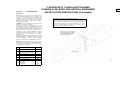
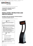
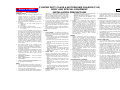
WARNING: F-53 Electrical Grounding Requirement
The two-piece frame rail design on the 2008MY F-Super Duty Class A
Motorhome Chassis (F-53) requires a ground path to be provided from
the rear of the vehicle. Failure to maintain this ground path may interfere
with the proper operation of any circuits grounded to the rear of the
frame. It is recommended that a 51mm {2.0 in] long fillet weld be
applied as shown to maintain this connection.
51mm [2.0 in] long fillet weld.
Remove paint before welding.
Passenger side frame rail only,
centered on frame face.
2009
MODEL YEAR
Page 163
1.
F53 MOTORHOME
F-SUPER DUTY CLASS A MOTORHOME
CHASSIS (F-53) BODY AND SPECIAL EQUIPMENT
INSTALLATION PRECAUTIONS (Continued)
LIGHTS CONTROLLED BY HEADLAMP SWITCH
The headlamp switch on the F-Super Duty Class A
Motorhome Chassis (F-53) utilizes one 20 amp fuse for
the headlamp high beam circuit and two 10 amp fuses
for low beam.
If your application involves splicing into the stop lamp
switch of a TorqueShift® equipped vehicle, please call
the Truck Body Builders Advisory Service at 1-877-8404338.
NOTE: Do not add marker lamps to the headlamp
circuit; a separate circuit is provided for the marker
lamps. Adding the marker lamps to the headlamp circuit
can result in an overload of the circuit. For full service
temperature range, the headlamp switch load should not
exceed 15 amp.
The F-Super Duty Class A Motorhome Chassis (F-53)
has a mechanical stop lamp switch mounted on the
brake pedal arm. These switches and associated wiring
are designed for a maximum load of 10.5 amp, which is
less than the fuse in the circuit, but ample for normal
stop lamp loads. Under no circumstances are total loads
in excess of this value permissible.
Wiring access for lights to be controlled by the headlamp
switch are provided at the front of the dash panel and at
the rear of the vehicle, and are identified by tags
attached to these wires.
If only turn signal function is desired for the added lights,
splice into the taillamp loom located at the rear of the
vehicle. Splice into wires tagged “RH turn signal only ‘or’
LH turn signal only.”
Splices and electrical loading (fusing and wire size
requirements) of these circuits must be in accordance
with general practices previously identified.
If both the turn signal and stop lamp function are desired
for the added lights, splice into the taillamp loom at the
rear of the vehicle into wires tagged, “RH turn w/brake
‘and’ LH turn w/brake.”
2.
LIGHTS CONTROLLED BY STOP LAMP SWITCH
AND TURN INDICATOR SWITCH
NOTE: Splicing into the stop lamp switch on vehicles
with TorqueShift® transmissions can interfere with the
proper functioning of PCM and speed control. This can:
•
Affect engine idle speed quality
•
Affect torque converter operation
•
Prevent the speed control from disengaging upon
braking
NOTE: The turn signal switch used on light trucks has a
maximum rated current of 6.5 amps for right and left
turning functions and 10 amps for stop lamp function.
Do not exceed these values on the turn signals.
The turn signal and emergency flasher system on the FSuper Duty Class A Motorhome Chassis (F-53) utilizes
an electronic flasher. For the turn signal function, the
electronic flasher is designed to accommodate five 2.1
amp lights; and for the emergency flasher function, it is
designed to accommodate ten 2.1 amp lights for
combination stop/turn and trailer lamps.
NOTE: Adding more lights than what is specified above
can result in reduced life and performance of the flasher.
3.
ADDED LIGHT OR ACCESSORIES
CONTROLLED BY ADDED SWITCHES
The added electrical switches and wiring must have
sufficient electrical capacity for the accessory load and
must be protected by appropriate fuses or circuit
breakers. Also, added current draw must not cause total
loads to exceed capabilities of the base vehicle wiring.
State, provincial, local laws may regulate the manner in
which the fog and driving lamps are used, or may
require additional equipment for the particular use
intended for the vehicle. It is the buyer’s/owner’s
responsibility to determine the applicability of such laws
to the buyer’s/owner’s intended use for the vehicle and
to arrange for the installation of required equipment.
2009
MODEL YEAR
5. WIPER DELAY MODULE
The Wiper Delay Module on the F-Super Duty Class A
Motorhome Chassis (F-53) is not internally protected for
a continuous high current load greater than 9.0 amps
and must be protected either internal to the wiper motor
or via inline protection such as a properly sized circuit
breaker. The existing 30 amp fuse in the fuse panel is
sized for the maximum allowable inrush current and
does not provide appropriate protection to the Wiper
Delay Motor
A/C PREP PACKAGE
1.
When horns are installed, the location must be as high
as possible with bell mouth of horn pointed downward.
4.
BATTERIES AND VOLTAGE REGULATOR
The battery location must be adequately ventilated,
accessible for servicing, protected from road splash,
and must also incorporate a shockless mounting.
The coach or chassis battery must not be located under
the air cleaner inlet to prevent ingesting any gas that
may be emitted from the battery.
Batteries should not be mounted in front of the radiator
or impede air flow through the radiator.
If the original equipment battery is replace by more than
one battery, or a battery of a larger capacity, the battery
charging power supply circuit must be checked and
revised to carry the additional loads.
F-Super Duty Class A Motorhome Chassis (F-53) has a
separate wire to maintain Keep Alive Power; PCM the
addition of a battery cut-off switch must not affect the
operation of this circuit.
The electronic voltage regulator base must always be
connected to the battery, engine chassis ground when
the ignition switch is in either the ON or START position.
The voltage regulator will be damaged if the connection
does not exist when the ignition switch is energized.
2.
The F-Super Duty Class A Motorhome Chassis (F53) comes with an R134a (non-CFC) air
conditioning prep package for use with a TXV
controlled A/C system. This package consists of a
compressor, condenser, high side lines with high
pressure switch, air recirculation baffles, and front
end accessory drive which are mounted to the
chassis, and a receiver/dryer with low pressure
cutoff switch.
Information on air conditioning refrigerant and
lubricant quantities are shown in the Ford Truck
Quality Program Guidelines binder.
Page 164
F53 MOTORHOME
F-SUPER DUTY CLASS A MOTORHOME
CHASSIS (F-53) BODY AND SPECIAL EQUIPMENT
INSTALLATION PRECAUTIONS (Continued)
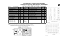
Circuit
Circuit #
Gauge
Color
Location
2009
MODEL YEAR
Fuse
Location
Fuse Size
• Accessory Feed (Accy’s & Run)
296
18
White-Purple
Top Side of Dash Panel (Part of 14A318)
F/P #5
10A
• Accessory Feed (Off & Run)
294
18
White-Lt. Blue
Top Side of Dash Panel (Part of 14A318)
F/P #38
10A
• A/C Switch
441
16
Red-Yellow
Top Side of Dash Panel (Part of 14A318)
• Backup Lamp
140
18
Black-Pink
Rear of Vehicle (Part of 14408)
F/P #33
10A
• Battery Feed
1049
16
Brown-Pink
Top Side of Dash Panel (Part of 14A318)
F/P #16
20A
• Blower Motor Feed
181
10
Brown-Orange
Top Side of Dash Panel (Part of 14401)
PDB #23
40A
• Brake Lamp Feeds
511
16
Lt. Green
Top Side of Dash Panel (Part of 14A318),
Front Side of Dash Panel (Part of 14A348)
-and Rear of Vehicle (Part of 14408)
F/P #9
20A
• Cigarette Lighter Feed
40
14
Lt. Blue-White
Top Side of Dash Panel (Part of 14A318)
PDB #22
20A
• Electric Brake Power
43
12
Dark Blue
Rear of Vehicle (Part of 14408)
PDB #13
30A
PDB #21
20A
—
—
• Fuel Pump Delivery Module Relay
1059
14
Lt. Blue-Orange
Power Distribution Box Relay #2
• Ground During Start
41
20
Black-Lt. Blue
Top Side of Dash Panel (Part of 14A318)
• Headlamp High Beam Feed
12
16
Lt. Green-Black
Front Side of Dash Panel (Part of 14290)
F/P #35
20A
• Headlamp Low Beam Feed (Left)
Headlamp Low Beam Feed (Right)
160
161
18
18
Dark Brown and White
Dark Green-Orange
Front Left Side of Dash Panel (Part of 14290)
Front Right Side of Dash Panel (Part of 14290)
F/P #31
F/P #25
10A
10A
• Horn Feed
6
16
Yellow-Lt. Green
Front Side of Dash Panel (Part of 14290)
PDB #17
20A
• Instrument Panel Lamp Feed
19
20
Lt. Blue-Red
Top Side of Dash Panel (Part of 14A318)
F/P #41
10A
• Interior Lamp Feed
53
18
Black-Lt. Blue
Top Side of Dash Panel (Part of 14A318)
and Rear of Vehicle (Part of 14408)
—
—
—
• Interior Lamp Feed (Ground)
402
20
Orange-Lt. Green
(Part of 14A318)
• LH Turn Signal (only) Feed
3
16
Lt. Green-White
Front Side of Dash Panel (Part of 14290)
and Rear of Vehicle (Part of 14408)
F/P #15
15A
• LH Turn w/Brake Signal Feed (Turn)
9
16
Lt. Green-Orange
Rear of Vehicle (Part of 14408)
F/P #1
20A
• Marker Lamp Feed (Park Lamp)
14
14
14
14
14
16
16
16
16
16
Brown
Brown
Brown
Brown
Brown
Front Side of Dash Panel (Part of 14290)
Front Side of Dash Panel (Part of 14A348)
Top Side of Dash Panel (Part of 14A318)
Middle of Vehicle (Part of 14405)
Rear of Vehicle (Part of 14408)
PDB #6
20A
• Park Brake Switch (Ground)
162
20
Lt. Green-Red
Top Side of Dash Panel (Part of 14A318)
• Radio Feed
137
18
Yellow-Black
Top Side of Dash Panel (Part of 14A318)
F/P #17
5A
• RH Turn Signal (only) Feed
2
16
White-Lt. Blue
Front Side of Dash Panel (Part of 14290)
and Rear of Vehicle (Part of 14408)
F/P #21
15A
• Climate Control Customer Demand Switch
391
16
Red-Lt. Blue
(Part of 12A581)
PDB #3
20A
NOTES — 14A032, 14A318, 17B587, 14408, 13A840, AND 18A840 WIRE HARNESS ASSY ARE PROVIDED IN DUNNAGE BOX.
NOTES — FUSE PANEL (F/P) IS LOCATED ON 14A032-A WIRE HARNESS PROVIDED IN DUNNAGE BOX.
NOTES — POWER DISTRIBUTION BOX (PDB) IS LOCATED ON 12A581 WIRE HARNESS LOCATED IN ENGINE COMPARTMENT.
* REFER TO OWNERS GUIDE FOR COMPLETE LIST OF FUSE AND RELAY CIRCUITS/COMPONENTS.
—
—
—
—
—
Page 165
F-SUPER DUTY CLASS A MOTORHOME
CHASSIS (F-53) BODY AND SPECIAL EQUIPMENT
INSTALLATION PRECAUTIONS (Continued)
F53 MOTORHOME
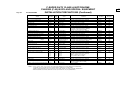
Circuit
Circuit #
Gauge
Color
•
•
•
•
•
•
•
•
•
Blower Motor Relay Ground
Electric Brake Controller
Electric Brake Ground
Hot During Start
LH Turn w/Brake Signal Feed (Brake)
RH Turn w/Brake Signal Feed (Turn)
RH Turn w/Brake Signal Feed (Brake)
Tach Output Clean
Trailer Backup Lamp
753
50
206
113
9
5
5
76
963
18
12
14
10
16
16
16
20
16
Yellow-Red
Red
White
Yellow-Lt. Blue
Lt. Green-Orange
Orange-Lt. Blue
Orange-Lt. Blue
Lt. Green-White
Black-Lt. Green
•
•
•
•
•
•
•
•
•
•
•
•
•
•
Trailer Ground
Trailer LH Turn/Stop Lamp
Trailer RH Turn/Stop Lamp
Trailer Running/Park Lamps
Trans Tach Output (Park)
Trans Tach Output (Neutral)
Vehicle Speed Output
Warning Chime — Seat Belt
Washer Pump Feed
Wiper Motor Feed — Common
Wiper Motor Feed — High
Wiper Motor Feed — Ignition
Wiper Motor Feed — Low
Wiper Motor Feed — Switch
206
52
64
962
1146
463
239
85
941
61
58
65
56
28
10
16
16
16
20
20
20
20
14
14
14
14
14
14
White
Yellow
Dark Green
Brown-White
Lt. Green-Red
Red-White
White-Orange
Brown-Lt. Blue
Black-White
Yellow-Red
White
Dark Green
Dark Blue-Orange
Black-Pink Stripe
Location
Fuse
Location
Fuse
Size
Top Side of Dash Panel (Part of 14401)
Front Side of Dash (Part of 14A348)
Front Side of Dash (Part of 14A348)
Top Side of Dash Panel (Part of 14401)
Rear of Vehicle (Part of 14408)
Rear of Vehicle (Part of 14408)
Rear of Vehicle (Part of 14408)
Top Side of Dash Panel (Part of 14401)
Top Side of Dash Panel (Part of 14A318)
and Rear of Vehicle (Part of 14408)
Rear of Vehicle (Part of 14408)
Rear of Vehicle (Part of 14408)
Rear of Vehicle (Part of 14408)
Rear of Vehicle (Part of 14408)
Top Side of Dash Panel (Part of 14401)
—
PDB #13
—
PDB #28
F/P #1
F/P #1
F/P #1
—
F/P #34
—
30A
—
30A
20A
20A
20A
—
10A
—
F/P #22
F/P #22
PDB #15
—
—
20A
20A
20A
—
Top Side of Dash Panel (Part of 14401)
Top Side of Dash Panel (Part of 14A318-A)
Front Side of Dash Panel (Part of 17B587)
—
—
F/P #11
—
—
30A
NOTES: 14A032, 14A318, 17B587, 14408, 13A840, and 18A586 WIRE HARNESS’S ARE PROVIDED IN DUNNAGE BOX.
FUSE PANEL (F/P) IS LOCATED ON 14A032-A WIRE HARNESS PROVIDED IN DUNNAGE BOX.
POWER NETWORK BOX (PNB) IS LOCATED ON 12A581 WIRE HARNESS LOCATED IN ENGINE COMPARTMENT.
2009
MODEL YEAR