1
First With Innovations That Last
2009 Update Manual
Copyright Shivvers Mfg. 2009
First With Innovations That Last
Table of Contents
EFI Wiring Kit
EFI Clutch Spike Kit
Hydro Belt Update Kit, SR1200
Spindles, Out-of-Warranty Rebuild
Flow Meter, How to Use
Belt Alignment
Interstate Batteries
Peco Warranty Procedure
Jack Recall
Quick Reference Guides:
Hydro Gear
Kohler Quick Reference
Kawasaki Top 50 Parts
Briggs & Stratton
Blade & Belt Quick Reference
Country Clipper Model Identification Chart
Copyright Shivvers Mfg. 2009
Country Clipper Update Manual
Kit # 629EB-001A
EFI Wiring
Addresses wiring issues among
designated serial numbers of The Boss
using 28 hp EFI engines
Country Clipper Update Kit # 629EB-001A
Country Clipper has identified up to four wiring issues that may affect early 28 hp
EFI mowers. While each mower may not realize all issues, a new kit is available to
resolve them:
1.
2.
3.
4.
Protection of the Fuel Line
Diagnostic Light incorrectly positioned; New control panel Decal
Incorrect Diagnostic Light function
Incorrect Hour Meter function; Oil Pressure Switch replacement
The new kit addresses issues of mowers prior to and including Serial Numbers listed
below. Mowers produced after these serial numbers are not affected.
Model
2852KOJ8-SR1205
2860KOJ8-SR1205
2872KOJ8-SR1205
2860KOT8-SR1205
2852KOT8-SR1205
2872KOT8-SR1205
Serial Number
647BA00000001
647BD00000026
647BG00000012
647BM00000014
647BN00000003
647BO00000010
Parts List: Update Kit # 629EB-001A
H-1094
E-5058
E-5071
E-5074
E-5059
E-5884
E-6078
E-6458
E-6098
P-11533
H-2336
629-651P
F-1158
F-1558
E-6277
629-674P
629-675P
Plastic Plug
Red Copper Wire #16
White Copper Wire #16
Black Copper Wire #16
Terminal, Blue, 16-14 Wires
Cable Tie, Nylon, 8”
Disconnect, Female
Disconnect, Female, Nylon
Packard Terminal, Female
Decal, Rh Fender Cap EFI
Hose Clamp
Bracket, Fuel Filter, 2”
Hex Nut, lock, 1/4-20
Capscrew, 3/8-16 X 7/8, Yellow Plated
Seat Switch, Relay Volt
Trim Edge 3”
Trim Edge 4”
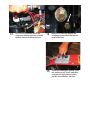
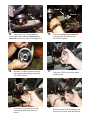
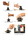
Issue 1:
Securing and
Protecting the Fuel Line on early 28 hp EFI Mowers
1
2
Clamp part # 629-651P;
Bolt part # F-1558;
Nut
part # F-1158; all provided in kit
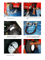
3
Locate the EFI fuel filter that is tied to the engine guard (right side). Re-
move the tie strap holding it in place.
Place clamp around the filter.
Secure filter to the engine guard with bolt & nut provided in the kit.
Part #s
629-675P
629-674P
4
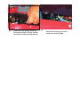
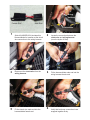
Note the two pieces of trim: One is cut to bend 900 and the other is straight.
5
Place angled trim on edge of side panel just above lower linkage. Place the straight piece on edge of frame.
P-12452
3
6
Locate the hole directly below the front arm rest hole. Pull the fuel line up and tie it in the hole with wire tie.
7
Pull the tie securely, but not so much as to stop fuel flow.
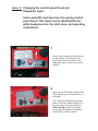
Issue: 2 Changing the control panel Decal and
Diagnostic Light.
Some early EFI machines have the wrong control panel Decal. This decal can be identified by the white background on the start, stop, and operating instructions.
1
Remove the old decal by first removing
the Hour Meter, Clutch Switch, and
Key Switch. (Note the location of the
Diagnostic Light; It is not in the correct
position.)
2
Apply the gray EFI decal provided in the
kit by aligning its cut-outs with those on
the fender.
Also, remove the Diagnostic Light and
place it in the hole marked “Engine” on
the new decal. Place the plastic plug
(Part # H-1094) in the hole vacated
by the light. Re-install the Hour Meter,
Clutch Switch, and Key Switch.
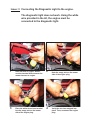
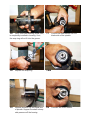
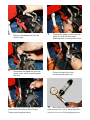
Issue: 3 Connecting the Diagnostic Light to the engine.
1
3
The diagnostic light does not work. Using the white wire provided in the kit, the engine must be
connected to the diagnostic light.
Near left front of engine, discon-
nect the terminal that connects the mower harness to engine.
2
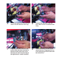
Place the white wire’s bare terminal into the empty slot on the mower side of the engine plug.
4
Note the empty slot on the mower side of the engine plug.
Verify the wire has snapped into place. Then, reconnect the engine plug. 5
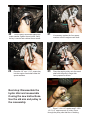
7
Route the white wire along the trac-
tor harness back toward the control panel.
6
Tie the white wire to the tractor har-
ness with wire ties from the kit.
Note photos 6, 7, and 8.
8
10
9
Remove the key switch from the fender cap to provide additional visibility.
11
Unhook the black wire from the light and tie it back along the harness.
12
Locate the engine code light in the fender cap.
Plug the covered terminal of the new white wire into the vacated terminal on
on the light. Then replace the key switch.
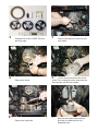
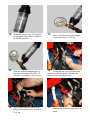
Issue 4: The Hour Meter does not work.
1
Note the relay provided in the kit.
2
Remove the black and green wires
connected to the hour meter.
87A
87
85
86
3
Note the terminals inside the relay are marked.
4
30
5
Connect the green wire from the hour meter to the 86 terminal in the relay.
6
Plug the black wire from the relay to the inside (left side) terminal on the hour meter. Place one end of the short red wire from the relay to the right hand or outside terminal.
7
8
Connect the black wire from the hour meter to the 30 terminal in the relay.
Locate the double red wire in the tractor harness. Plug opposite end of red wire going to hour meter into the double wire.
9
11
Verify that a good connection is made, as the two connectors can be difficult to push together.
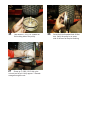
Locate the 1/4” bolt used as a stop bolt for the hydro oil cooler. 12
Remove the stop bolt. 10
13
After removing the bolt, place the relay over the bolt hole and reinstall the bolt. Secure it with a lock nut. 14
Be sure to rotate the bolt so the oil cooler frame will set flat on the head of the bolt.
15
Check the code light: Quickly cycle the switch on-off, on-off, and then on again. Verify it blinks 6 times, pauses, then blinks a 7th time.
First With Innovations That Last
Country Clipper Update Manual
Kit # 629EE-001A
Clutch Electrical Spikes
Addresses protection against electrical
spiking of the clutch on The Boss
mowers with 28 hp Kohler EFI engines
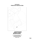
P-12486
Service Bulletin 092608
Products affected:
Boss SR1205 mowers equipped with 28 hp Kohler EFI engines
Clutch Spike Kit (629EE-001A)
Particular Boss SR1205 mowers with 28 hp Kohler EFI engines have no spike protection for
the clutch. A potential exists when shutting off the blade clutch that an electrical spike could
destroy the EFI engine’s computer. To reduce this potential, Country Clipper developed Clutch
Spike Kit part #629EE-001A that must be inserted into the clutch wire connection. Affected
Boss mowers are those with serial numbers including and prior to the following:
Boss Model
2852KOJ8-SR1205
2860KOJ8-SR1205
2872KOJ8-SR1205
2860KOT8-SR1205
2852KOT8-SR1205
2872KOT8-SR1205
Serial Number
647BA1
647BD26
647BG12
647BM14
647BN3
647BO10
Kits are now available from the factory. All mowers prior to and including the above serial
numbers need a Clutch Spike Kit installed to prevent potential computer failure.
For more information, please contact your distributor’s Service Manager.
Country Clipper Mowers
Corydon, Iowa 50060
(800) 344-8237
www.countryclipper.com
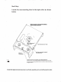
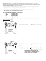
wiring
Harness
Female End
Male End
Clutch Wire
1
3
5
Spike Kit #629EE-001A includes this harness/diode for insertion at the clutch wire connection to the wiring harness.
Disconnect the clutch wire from the
wiring harness.
Fit the clutch wire male end into the
harness/diode female end.
2
4
6
Locate the connection between the clutch wire and wiring harness
(near the hydro oil filter).
Fit the harness/diode male end into the wiring harness female end.
Verify that both new connections have snapped together firmly.
Country Clipper Update Manual
Kit # 629EF-001A
Addresses the Hydro Drive Belt for
Boss SR1200 Mowers
P-12490
11/08
15
6
17
4
16
14
21
9
3
18
8
11
10
7
13
19
20
12
2
1
5
Item
1
2
3
4
5
6
7
8
9
10
11
12
13
14
15
16
17
18
19
20
21
Qty Part No.
1
1
1
1
1
1
1
1
1
1
1
1
1
2
1
2
1
3
2
1
1
B-2265
B-2030
F-1293
F-1966
629-668P
629-670P
629-669P
F-1765
F-1158
620-050P
F-1544
F-1125
F-1009-02
F-1521
D-3799
647-147P
647-148P
F-1228
D-3541
621-113P
P-12489
Description
BOX, CARDBOARD 4" X 10" X 22"
6 X 8 SACK
1/2-13 x 2" Capscrew
1/2-13 THIN NYLOC NUT
SPACER,IDLER,1200 KIT
SPRING, IDLER,1200 KIT
STAND-OFF,SPRING MOUNT
1/4-20 x 3" Capscrew
1/4-20 Stover Nut
Washer
5/16-18 x 3" Capscrew
5/16-18 Stover Nut
5/16" Flat Washer
1/2" Washer
V-Belt A-57
5-1/2" Hydro Pulley
Motor Pulley
1/4-20 x 1/4" Set Screw
5 MM X 20 MM KEY
1/4"sq x 1-1/4" Key
CARTON TAG,HYDRO BELT DRIVE KIT
1
2
4
6
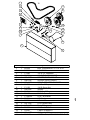
See parts list for Kit # 629EF-001A on previous page.
Remove the clutch.
Remove the hydro belt.
3
Remove the engine-to-deck belt and set it aside.
5
Cut the wire ties that hold the clutch wires. Then, unplug the clutch wires from the
wire harness; set the clutch aside.
7
Remove the engine pulley and key.
Note the four washers that only Kawasaki uses.
8
10
12
Loosen the set screws on the hydro pulleys.
Remove the hydro pulleys.
Remove the hydro idler spring anchor.
9
11
13
Remove the locator bolts from the pump shaft.
Remove the hydro idler.
Remove the hydro oil drain chute.
Stand-off
Bolt
14
Place the 1/4 x 3” bolt downward
through the frame; slide the spring mount
stand-off onto the bolt. (Also, see image 28.)
16
18
Place the F-1228 set screws into the new engine pulley and also into both 5.5” hydro pulleys.
Slide the 5.5” hydro pulley onto the
pump shaft. Make sure the key is
secure.
Washer
15
17
19
Place the spring mount stand-off
onto the bolt using washer part
# 620-050P; tighten.
Place the D-3541 key into the hydro shaft key way.
Place the locator bolt and washer into the end of the pump shaft and tighten.
20
Pull the pulley downward against the
locatorwasher; tighten the set screw. Verify
the key is secure and catches the set screw.
22
Place the 1/4” sq x 1-1/4” square key
into the engine crank shaft under the spacer washers.
21
23
If necessary, replace the four spacer washers onto the engine crank shaft.
Place the engine pulley onto the crank
shaft with the pulley’s longer hub
facing upward as shown.
Next step: Disassemble the
hydro idler and reassemble
it using the new instructions.
Use the old arm and pulley in
the reassembly.
24
Place F-1521 1/2” washer and F-1293 1/2-13 x 2” capscrew onto 4” pulley. Place
through the pulley side that has no bushing.
25
27
Use another F-1521 1/2” washer on the bushing side of the pulley.
Screw an F-1966 1/2-13 thin nyloc nut onto end of bolt. Verify approx. 3 threads
emerge through the nut.
26
Screw bolt into threaded hole of idler arm. Verify the pulley is on same side of the arm as the pivot bushing.
Next Step:
Locate the new mounting hole for the hydro idler as shown
below.
28
Place the 1/4 x 3” bolt downward through this hole, then slide
the spring stand-off (parts list item # 7) onto the bolt as shown in
images 14 & 15.
Spacer
The long hook on the idler spring fastens over the idler pulley bolt.
29
Using the new F-1544 5/16-18x3 cap-
screw and 629-668P spacer, mount the idler
arm as shown. Note the new D-3799 bolt.
30
Reinstall the clutch; torque to 55 ft. lbs. Important: Tie the clutch wire back along the
clutch stop to keep it out of the way.
31
Replace the engine-to-deck belt.
First With Innovations That Last
Country Clipper
Spindle
Replacement Instructions
for
“Out of Warranty Spindles”
1
Remove spindle from the mower deck and clean it.
2 Remove the blade spacer.
3
Remove the thrust washer as it falls free.
4
Use snap ring pliers to remove snap ring from bottom of the spindle.
5
Remove the seal washer.
4-B
6
Remove woodruff key from bottom
blade side of the spindle shaft.
6-B
7
Remove woodruff key from top end (pulley end) of the spindle shaft.
7-B
8
Remove the grease zert.
9
Using a press, remove the shaft
from the housing. This leaves one bearing
on the shaft and one in the housing.
10
Remove the bearing from the shaft.
11
Inspect the spindle shaft for wear or damage.
12
Press old bearing out of the spindle housing. Inspect the housing for wear or other damage.
13
Get two new D-3058 bearings.
14
Place a bearing at each end of the shaft; then push the shaft through the housing.
15
Place spindle in the press. Press both bearings into the housing at the same time.
16 Verify that lower bearing (blade side)
is completely installed in housing. If not,
the snap ring will not fit into the groove.
17
18
Replace the snap ring.
18-B
19
Replace woodruff key into blade end of spindle. Support the shaft to keep side pressure off the bearing.
20
Position the seal washer into the blade side of the spindle.
Reinstall the thrust washer.
20-B
22
Replace the woodruff key on pulley side of the spindle.
21
Reinstall the blade spacer. It should position without much pressure.
23
Replace the grease zert.
Reinstall the spindle onto the mower to complete the repair.
First With Innovations That Last
Country Clipper Update Manual
Flow Meter
Using a Flow Meter to test
hydraulic pressure of
hydrostatic pumps
P Series Flow Test Kit, Hydro-Gear part no. 70661
A flow test kit allows dealers to isolate a pump from
a wheel motor to determine if the pump is faulty.
The kit can simulate a wheel motor load.
1
Jack the mower up.
2
Place jack stands under the mower frame.
Restriction
Valve
3
5
Verify the oil filter is part # H-2026 and that it is not plugged.
Remove the wheel.
4
Test oil flow in the pump using a flow meter. (Note: Restriction Valve)
6
Remove the return line from the wheel motor.
8
Disconnect the input line from the wheel motor, which is positioned to the front. 10
Relocate plastic caps from the flow
meter lines to the wheel motor fittings.
These protect against debris.
7
9
11
Connect the pump’s return line with either line from the flow meter. Matching lines is not important here.
Fasten the input line to the
remaining flow meter line.
Start engine and reach full speed so
hose becomes hot to touch. Adjust Restriction
Valve (not shown) to 300 lbs gauge pressure.
12
While this pump reads 10.5 gal/min, good pumps may read 6-10 gal/min at 300 lbs pressure.
14
View the flow rate gauge again. In this case, the drop is less than 1/2 gal/min, a good pump. (See instruct.)
16
Reconnect the input hose to front fitting of the wheel motor. Torque to
35 ft. lbs.
13
Next, move Restriction Valve again to raise pressure to 1100 lbs.
15
To end the test, turn off engine and
disconnect the flow meter. Remove the
input hose from the flow meter.
17
Remove the return line from the flow meter.
18
20
Reconnect the return hose to rear fitting of the wheel motor. Torque to 35 ft. lbs.
Replace the wheel back onto the mower.
19
21
Relocate the plastic covers back onto the flow meter lines. These protect against debris.
Country Clipper uses a torque stick set to 75 lbs.
Note:
It will not be necessary to
bleed the hydraulic lines after
the testing procedure.
22
Tighten lug nuts and torque to
75 ft. lbs.
First With Innovations That Last
Country Clipper Update Manual
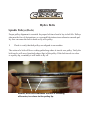
Hydro & Deck Belt
Alignment
Idler Arms, Spindle Pulleys, and Belts
Hydro Belts
Spindle Pulleys (Deck)
Proper pulley alignment is essential for proper belt travel and is key to belt life. Pulleys
also must be free of obstructions, as even small deviations in an otherwise smooth pulley face can cause the belt to break or fly off a pulley.
1
Check to verify that belt pulleys are aligned to one another.
The action of a belt will leave a shiny path along where it travels on a pulley. Verify the
belt travels well away from both edges (lips) of the pulley. If the belt travels too close
to a pulley lip, eventually it will break or fly off.
Shinier, worn area indicates the belt is traveling
off-center, too close to the pulley lip.
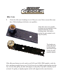
Idler Arm
2
Check the idler arm’s bushings to see if they are worn. More current idler arms have Teflon bushings with better wear qualities.
Older idler arms use a smaller
bushing more susceptible to side
pressure and wear. As the
bushing wears, belt tension
pushes the arm upward to misalign the pulley.
The bushing on
newer idler arms
is much heavier
and wears longer
to keep the belt
properly aligned.
If the idler arm fastens to a tab, such as on JAZEE and JAZEE PRO models, verify the
tab is not bent or angled in any way. If a belt travels at a slightly angled path across the
face of a flat idler pulley, the belt will migrate to the pulley’s lip and eventually fly off
or break. If a pulley is slightly angled, its belt will migrate in the same direction.
The example below shows a bent motor mount tab. This has caused the idler arm and
its pulley to operate on an uneven plane. In this illustration, the belt rides too “high”
toward the pulley’s upper lip. A belt will migrate on a pulley in the direction of any
misalignment. If the tab is not readjusted back to level, this belt eventually will fray
along its top edge and break or fly off. Motor mount tab is bent upward
Deck Belts
While spindle pulleys are aligned on a level plane with one another, the plane on which
clutch/idler pulleys operate changes as the belt moves toward the deck from the rear of
the mower. The plane changes as the deck is raised or lowered.
As the deck height has been lowered, the belt also becomes
lower as it moves from the clutch area into the double idler.
Change in level is controlled with a double idler (pulleys) and belt guides. From the
clutch, the belt moves forward entering the left side double idler’s V-pulley. Belt guide
part # 668-022P fixed atop the pulley helps this process.
The belt then moves into the double idler’s second pulley (flat pulley). Belt guide part #
660-060P is used to reduce the belt’s potential to come off the flat pulley. This guide must
be set so that it cannot be pulled into the belt if the double idler flexes. Upon leaving the
double idler, the belt now should be on the same level plane as the spindle pulleys.
Belt Guide part # 668-022P
Part # 660-060P
If a belt does not travel properly while moving throughout the series of spindle pulleys,
any of the deck pulleys may have become misaligned or the belt is rubbing against an
obstruction such as a bolt, pulley cover, etc. In some cases, a defective pulley may be the
issue.
After the belt travels around the right spindle pulley, it enters the right side idler pulley. This idler pulley is rigid and is responsible for changing the belt’s plane back to the
clutch. Belt guide part # 660-060P located on the top of this pulley must be set as close as
possible to the belt without obstructing it.
Issues causing belt failure:
•
•
•
•
•
•
Bent idler arm
Worn idler arm bearing or bent, twisted motor mount tab
Pulley that is misaligned, tilted, or has sharp or blunt obstructions
Improper positioning of belt guide
Defective belt
Belt age and hours of usage
##
First With Innovations That Last
Country Clipper Update Manual
Interstate Batteries
Maintenance & Charging
Battery Maintenance
All batteries, when not in use, will need to be charged at some
point in time. Below is information to help keep your batteries
performing at their peak.
• The smaller the battery, the quicker it discharges.
• Warmer temperatures accelerate the discharge process.
• A voltmeter is the best way to determine if a battery needs
charging.
• If a voltmeter is not available, a battery should be recharged
every six months.
• The following chart helps in knowing a battery’s state of
charge:
Voltage
State of Charge
12.6 volts
12.4 volts
12.2 volts
12.0 volts
11.8 volts
100%
75%
50%
25%
0%
• Every battery should be charged on arrival.
• Charge at 2.4 amps for 4 - 6 hours.
• When battery becomes warm, turn charger down.
First With Innovations That Last
Country Clipper Update Manual
Peco Grass Collection Systems
Warranty Procedures & Pricing
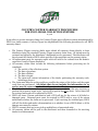
COUNTRY CLIPPER WARRANTY PROCEDURES
FOR PECO GRASS COLLECTION SYSTEMS
8/1/08
In an effort to process warranty claims for Country Clipper grass collection systems manufactured by
PECO in a timely manner, Country Clipper has implemented the following procedures for all PECO
warranty claims:
1. The Country Clipper servicing dealer must submit all warranty claims directly to their
distributor using the standard Country Clipper warranty claim form. All claims must be
reviewed and signed by the distributor’s designated service personnel. The distributor will
then forward the claim to PECO within 30 days of the repair date on the warranty claim.
2. All replacement parts for warranty repair work will need to be ordered from the dealer’s
respective Country Clipper distributor.
3. All warranty claims must include the following information before processing can be
completed:
a. The serial# of the collection system.
b. The date of purchase.
c. The date of failure.
d. The date of repair.
e. The name and contact information of the dealer performing the warranty work,
including a phone#.
4. The claim must describe as thoroughly as possible the nature of the failure and the repair
work that was performed. All claims that do not include the information in #3
and #4 may be returned to the distributor for clarification.
5. The dealer must indicate on the warranty claim the amount of labor that was necessary to
perform the warranty repair work. Labor will be paid at $4500 per hour. Labor times will
be reviewed and approved or adjusted by PECO.
6. PECO will issue a return authorization and a UPS call tag for the return of all failed or
damaged parts. Returned parts must be received by PECO with a copy of the return
authorization before the claim can be processed. Upon receiving the returned part, PECO
will call the dealer and make a determination as to whether it was a PECO defect or if the
damage was caused by misuse.
7. PECO’s warranty does not cover pick-up and delivery of warranted units.
8. All warranty claims will be paid to the distributor and then forwarded to the servicing
dealer for reimbursement.
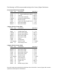
The following is a PECO recommended stocking list for Country Clipper Distributors: Easy Dump Collection System (EDBS) Part# Qty Description Retail Price A0645 8 Small 4‐Blade Impeller $ 225.00 A0046 5 ¾” Tapered Bushing for A0645 $ 37.90 A0709 5 Boot Kit $ 252.00 A0738 1 Door Frame Assembly $ 170.00 E4004A 5 Blower Housing Assembly $ 378.00 E6009 5 Blower Cone 8” $ 53.50 K1442 1 Super Latch Adjusting Ball Joint $ 5.26 M0243 5 Belt, Kevlar A49K $ 9.67 M0250 5 Belt, Kevlar A30K $ 11.50 3 Bagger Collection System (PBS) Part# Qty Description Retail Price G0002 12 Collection Bag 3.3 Cu. Ft $ 63.16 J4005 1 Flexible Draw Latch $ 7.37 E4004B 2 Blower Housing Back $ 193.00 E4004F 2 Blower Housing Front $ 193.00 M0243 5 Belt, Kevlar, A49K $ 9.67 M0250 5 Belt, Kevlar, A30K $ 11.50 V1054 5 Inlet 6” $ 90.50 E1902 5 Welded Boot $ 202.11 2 to 3 lengths Hose 8” X 218” $ 1.58/In. J6006 15 Hose Clamps 7 & 8” $ 7.37 2 Bagger Collection System (JZBS) Part# Qty Description Retail Price G0004 10 Collection Bag 2.9 Cu. FT. $ 63.16 M0268 10 Belt, Kevlar, A47K $ 10.50 M0267 10 Belt, Kevlar, A28K $ 11.29 V1160 10 Boot, Plastic w/holes $ 77.90 V1162 10 Boot, Plastic, holes $ 77.90 V0016 10 Blower Cone 6” $ 29.47 2 to 3 lengths Hose 6” X 218” $ 1.26/In. J6011 15 Hose Clamps 6” $ 7.37 V0015 10 Blower Housing $ 71.58 V0017 10 Catcher Top $ 107.34 V0019 10 Inlet $ 28.95 J4009 10 Rubber Strap w/Hook $ 7.37 Parts will need to be ordered by the distributor direct from PECO. Country Clipper will not stock replacement PECO parts for distribution. First With Innovations That Last
Country Clipper Update Manual
Recall
Jack Tools & Kits
Recall Alert
U.S. Consumer Product Safety Commission
Office of Information and Public Affairs
Washington, D.C. 20207
September 24, 2008
Alert #08-DRAFT
Shivvers Manufacturing Recalls Lawn Mower Jacks Due to
Collapse Hazard
The following product safety recall was voluntarily conducted by the firm in cooperation with
the CPSC. Consumers should stop using the product immediately unless otherwise instructed.
Name of Product: Jack Lift Tools and Kits
Units: About 450
Manufacturer: Shivvers Manufacturing Inc., of Corydon, Iowa
Distributor: Country Clipper, a division of Shivvers Manufacturing Inc. of Corydon, Iowa
Hazard: The jack lifts can have threads stripping or the nuts breaking, resulting in the shaft
slipping and the mower falling from its stand-up position. This could cause serious personal
injury to the consumer or property damage.
Incidents/Injuries: Shivvers has received five reports of jack lift failures and 37 warranty
claims for replacement parts.
Description: The recalled jacks are used for lifting the lawn mower during service or
maintenance. Two versions of this jack model have been manufactured. Version number one
was made with a nylon nut and version number two was made with a sintered bronze nut. These
recalled jacks were sold separately and on Charger, JAZee and Boss riding lawn mowers.
Sold by: Country Clipper dealers nationwide from May 2007 through June 2008 for about $150
for the jack, and about $225 for the jack kits.
Manufactured in: United States
Remedy: Consumers should immediately stop using the jacks and contact their local service
dealer to have their lawn mowers repaired at no charge.
Consumer Contact: For additional information, contact your local dealer or Country Clipper at
(800) 344-8237 between 8 a.m. and 4:30 p.m. CST Monday through Friday or visit the firm’s
Web site at www.countryclipper.com.
August 13, 2008
IMPORTANT CONSUMER PRODUCT SAFETY RECALL
Dear Country Clipper Distributor,
This letter is regarding a safety recall of the QRS Deck Jack Lift Tool. This recall supersedes both Service
Bulletins 011008 and 062008 and all jacks and jack kits in the field as well as in distributor and dealer
inventory will need to be replaced. Replacement of these jacks will be handled through our normal warranty
claim procedures. Your dealers will be provided with a special recall warranty claim form that they will
submit to you for reimbursement.
Replacement jacks with a redesigned nut (part# 629-653A) will be available the week of August 18, 2008.
This part# will need to be ordered for mowers that have jacks already installed on the unit. For jack kits that
the distributor and dealer elect to stock for aftermarket sales, the JAZEE/BOSS Jack Kit catalogue# is JKJB,
and the Charger Jack Kit catalogue# is JKCH. An updated Accessories Price List that includes these kits will
follow shortly.
Our goal is the replacement of all jacks as soon as possible in the field, including those in dealer and
distributor inventory. We can only do this with your assistance. Enclosed are copies of our communication
with your dealers, and to the retail purchasers of any 72” Boss mower that was equipped with the affected
jacks, instructing them to contact their Country Clipper dealer to have their jacks replaced. Notification of
remaining owners of jacks and jack kits will be the responsibility of the dealer. Please do not notify your
dealers and customers by blanket mail regarding this factory recall.
Enclosed are Return Authorizations and call tags for the return of any jacks or jack kits in your inventory. The
distributor will then need to reorder kits and jacks for field replacement and for stock. Dealers will need to
order replacement jacks from their respective distributor. Although it will not be necessary to reorder the same
quantity of kits and jacks returned to Country Clipper, it will be necessary for the distributor to reorder as this
is not an automatic one-for-one replacement program.
We appreciate your efforts, cooperation, and patience, and we are confident that as we administer this safety
recall, Country Clipper products will continue to be regarded as premier products in the market place.
Best Regards,
Dennis Ervin
August 26, 2008
IMPORTANT SAFETY RECALL
Re: QRS Deck Jacks and Kits
Dear Country Clipper Dealer,
In cooperation with the Consumer Product Safety Commission, Shivvers Manufacturing is conducting the
safety recall of the QRS Deck Jack Lift Tool. You have recently been contacted regarding the replacement of
the QRS Deck Jack Lift Tools and related kits as specified in Service Bulletins 01108 and 062008. A small
number of these jacks, both with the nylon nut and its recent replacement with the brass nut, have experienced
malfunctions. To eliminate these malfunctions, a replacement jack with a redesigned nut (part# 629-653A)
and is currently available to order.
Our goal is the replacement of all jacks as soon as possible in the field, including those in your inventory.
These jacks and jack kits include the new JSLTa and JSLTb kits, as well as any new 629-622A replacement
jacks for 72” units, and the original JDLT-QRSCH and JDLT-QRSJZ kits, and jack part# 629-553A still
remaining in the field and in your inventory. Country Clipper will also be communicating to the retail owners
of any 72” Boss mower that was equipped with the affected jacks, recommending to them that they contact
their Country Clipper dealer to have their jacks replaced. It will be the responsibility of the dealer to contact
any remaining owners of jacks and jack kits to instruct them to have their jacks replaced and to schedule a
service appointment.
This safety recall supersedes both Service Bulletin 011008 and 062008 and all jacks and jack kits listed
above will need to be replaced. On kits installed on mowers, only the jack will need to be replaced, not other
kit components. Please refer to the instructions that will accompany the new jack for installation procedures.
Jack kits will be available soon after for you to stock and sell after market.
Replacement jacks will be covered by warranty and will be installed at no cost to the customer through our
normal warranty claim procedures. Country Clipper will reimburse the dealer for ½ hour of labor per the
dealer’s posted shop labor rate to replace the jack, plus $50 for a pickup and delivery fee. All jacks must be
returned to the factory in order for the dealer to receive payment for these warranty claims. Enclosed is
a return authorization, a UPS call tag to return the recall jack, and a special warranty claim form to be
submitted to your distributor for reimbursement. Please include the return authorization with any return parts.
Failure to do so may result in a delay in issuing credit to you.
Your distributor will be in close contact with Country Clipper as we administer this safety recall. If you have
any questions regarding this recall, please feel free to call us at 800-344-8237. We appreciate your
cooperation in this matter during this very busy season.
Thank you,
John Grimes
Service Manager
Country Clipper Mowers
Quick
Reference Guide
Hydro Gear
Technical Specifications - Integ ......... Hydrostatic T... nsoxles
0-..11 ' .. n...,.)o l od""'on
...
- 'nput Spood.
•
-~
>OIII)~/36OI)a..-t
,-
- "_"-
,'" 120')
~-
"'" J-06'I
'''''1'''''
'''I''')
'001"7)
'OOfUll
=~
...... 'r _
""'I' ...)
GlIIIl)
' 00)2'7)
3001'63)
~-
""'I'....
' 00)2'7)
GlIIIlI
""1''''
Output'_
,
•
_ h t on n ... 1_
•
•
•
...... 00-_
...... 'r_
...... . hoftDIo_
...... . hoft
.noI O •• on.
......
...
unhl
,.DO )2>•.0)
- --'
....
-- -...
.,~
LOOI" ...
...-
~,
Pa.td"" ..........
_ht o fUn~
~
'"1"1
"
(''-'')
Kohler (Command Twin) quick reference for Country Clipper
Air Filter
Pre Cleaner
Inner Filter
Oil Filter
Dipstick
Carb Kit
Starter
Charge Coil
Ignition Modules
Spark Plugs
Fuel Filter
Engine Oil
Regulator/Rectifier
Head Gaskets
Intake Gaskets
Exhaust Gaskets
Breather Hose
Top Seal
Bottom Seal
Fuel Solenoid
Knob for AC
Breather Gasket
Flywheel Key
Fuel Pump
Carb
27hp
CV740-0012
23hp
CV23-75613
25hp
CV730-0030
20hp
CV20-65595
23hp
CV23-75601
30hp
CV750-0013
25 083 01-S
N/A
25 083 04-S
12 050 01-S
24 038 04-S
24 757 20-S
25 098 09-S
54 755 09-S
24 584 36-S
RC12YC
25 050 22-S
25 357 05-S
41 403 09-S
24 841 03-S
24 041 01-S
24 041 49-S
24 326 54-S
24 032 01-S
52 032 08-S
N/A
25 324 02-S
24 041 51-S
X-42-15-S
24 393 16-S
24 853 92-S
45 083 02-S
45 083 01-S
N/A
12 050 01-S
24 038 04-S
24 757 46-S
25 098 09-S
237878-S
24 584 45-S
RC12YC
24 050 22-S
25 357 05-S
41 403 09-S
24 841 02-S
24 041 01-S
24 041 49-S
24 326 03-S
24 032 01-S
52 032 08-S
N/A
25 341 04-S
24 041 51-S
X-42-15-S
24 393 16-S
24 853 97-S
25 083 01-S
N/A
25 083 04-S
12 050 01-S
24 038 04-S
24 757 18-S
25 098 09-S
237878-S
24 584 45-S
RC12YC
25 050 22-S
25 357 05-S
41 403 09-S
24 841 03-S
24 041 01-S
24 041 49-S
24 326 54-S
24 032 01-S
52 032 08-S
N/A
25 324 02-S
24 041 51-S
X-42-15-S
24 393 16-S
24 853 92-S
45 083 02-S
45 083 01-S
N/A
52 050 02-S
24 038 04-S
24 757 18-S
25 098 09-S
237878-S
24 584 45-S
RC12YC
24 050 10-S
25 357 05-S
41 403 09-S
24 841 01-S
24 041 01-S
24 041 49-S
24 326 03-S
24 032 01-S
52 032 08-S
24 757 22-S
25 341 04-S
24 041 51-S
X-42-15-S
24 393 16-S
24 853 50-S
25 083 01-S
N/A
25 083 04-S
12 050 01-S
24 038 04-S
24 757 46-S
25 098 09-S
237878-S
24 584 45-S
RC12YC
25 050 22-S
25 357 05-S
41 403 09-S
24 841 02-S
24 041 01-S
24 041 49-S
24 326 54-S
24 032 01-S
52 032 08-S
24 757 45-S
25 324 02-S
24 041 51-S
X-42-15-S
24 393 16-S
24 853 108-S
25 083 01-S
N/A
25 083 04-S
12 050 01-S
24 038 04-S
24 757 51-S
25 098 09-S
237878-S
24 584 36-S
RC12YC
24 050 10-S
25 357 05-S
41 403 09-S
24 841 03-S
24 041 01-S
24 041 49-S
24 326 78-S
24 032 01-S
52 032 08-S
24 757 50-S
25 324 02-S
24 041 51-S
X-42-15-S
24 393 16-S
24 853 103-S
2/9/2007
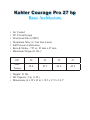
Kohler Courage Pro 27 hp
Basic Architecture
•
•
•
•
•
•
•
Air Cooled
90o V-twin Design
Over Head Valve (OHV)
Aluminum Alloy w/ Cast Iron Liners
Full Pressure Lubrication
Bore & Stroke - 725 cc: 83 mm x 67 mm
Maximum Torque (ft. lbs.):
HP
20
23
25
27
Max.
Torque
38.4
43.5
44.8
45.4
• Weight: 91 lbs.
• Oil Capacity: 2 qt. (1.9L)
• Dimensions (L x W x H in.): 18.5 x 17.8 x 14.1”
Kohler Courage Pro 27 hp
Spare Parts, Recommended
Engine Quantity
Part No.
Description
5+
10+
24 032 19-S
25 032 06-S
25 050 34-S
24 841 03-S
Seal Oil, Front
Seal Oil, Rear
Filter, Oil
Kit, Head Gasket
1
1
5
1
2
2
10
3
24 099 03-S
24 584 52-S
41 403 10-S
25 132 12-S
24 050 13-S
24 393 16-S
32 853 12-S
24 757 46-S
32 083 08-S
32 083 06-S
32 755 01-S
24 041 49-S
32 411 04-S
32 098 01-S
32 522 02
Switch, Oil Pressure
Module, Ignition
Regulator-Rectifier
Spark Plug
Filter, Fuel
Pump, Fuel
Carburetor
Kit, Carb. Repair
Element, Air Filter
Precleaner
Overhaul Gasket Set
Gasket, Exhaust
Rod, Push
Starter, Electric
Short Block
1
1
1
2
3
1
1
1
3
3
1
2
2
1
0
1
2
1
4
5
2
2
2
5
5
2
2
2
2
1
19HP Kawasaki Engine
FH601V TOP 50 PARTS
RANK
1
2
3
4
5
6
7
8
9
10
11
12
13
14
15
16
17
18
19
20
21
22
23
24
25
26
27
28
29
30
31
32
33
34
35
36
37
38
39
40
41
42
43
44
45
46
47
48
49
50
ITEM NUMBER
49065-2078
49019-7001
49065-2071
11013-7009
11013-7024
11060-7016
670D2016
11013-7027
21171-7013
11013-7020
92049-7001
11029-7012
11013-7019
12011-2056
92210-0003
11060-7013
59071-7004
92049-7011
49116-7001
92072-7009
172G0818
49040-7001
92049-7010
21163-7010
317R0800
92171-7005
12009-7001
11060-7011
92049-7005
11004-7006
92004-7006
11029-7015
130G0612
92004-7009
92210-7004
11065-7006
11011-6001
21066-7011
11060-7024
11060-7012
92140-7002
92153-7019
130T0850
92066-7003
311B0600
92015-2253
92009-2341
461F0800
13116-7002
92171-7009
DESCRIPTION
OIL FILTER
FILTER-FUEL
OIL FILTER
ELEMENT-AIR FILTER
ELEMENT-AIR FILTER
GASKET
O RING
ELEMENT-AIR FILTER
COIL-ASSY-IGNITION
ELEMENT-AIR FILTER
SEAL-OIL
ELEMENT-AS
ELEMENT-AIR FILTER
COLLET
NUT
GASKET,ROCKER
JOINT
SEAL-OIL
VALVE-ASSY
BAND
STUD 8X18
PUMP-FUEL
SEAL-OIL
STARTER-ELECTRIC
NUT
CLAMP
RETAINER-VALVE
GASKET
SEAL-OIL
GASKET-HEAD
STUD
ELEMENT-ASSY A/F
BOLT,FLANGED
STUD
NUT
CAP
CASE/NUT A
REGULATOR-VOLTAGE
GASKET
GASKET,CRANKCASE
BALL
BOLT
BOLT-FLANGED
PLUG
NUT 6MM
NUT
SCREW
WASHER SPRING
ROD-PUSH
CLAMP
25HP Kawasaki Engine
FH721V TOP 50 PARTS
RANK
1
2
3
4
5
6
7
8
9
10
11
12
13
14
15
16
17
18
19
20
21
22
23
24
25
26
27
28
29
30
31
32
33
34
35
36
37
38
39
40
41
42
43
44
45
46
47
48
49
50
ITEM NUMBER
49065-2078
49019-7001
49065-2071
11013-7009
11013-7024
11060-7016
11013-7027
21171-7013
11013-7020
670D2016
92049-7001
11013-7019
11029-7012
12011-2056
92210-0003
59071-7004
11060-7013
92049-7011
49116-7001
92171-7005
92072-7009
92049-7010
172G0818
49040-7001
21163-7010
317R0800
11060-7011
12009-7001
92049-7005
11004-7006
92004-7006
92004-7009
130G0612
11029-7015
11065-7006
92210-7004
11011-6001
21066-7011
92210-7019
11060-7012
11060-7024
92140-7002
92153-7019
130T0850
92066-7003
311B0600
92015-2253
92171-7009
92009-2341
13116-7002
DESCRIPTION
OIL FILTER
FILTER-FUEL
OIL FILTER
ELEMENT-AIR FILTER
ELEMENT-AIR FILTER
GASKET
ELEMENT-AIR FILTER
COIL-ASSY-IGNITION
ELEMENT-AIR FILTER
O RING
SEAL-OIL
ELEMENT-AIR FILTER
ELEMENT-ASSY
COLLET
NUT
JOINT
GASKET,ROCKER
SEAL-OIL
VALVE-ASSY
CLAMP
BAND
SEAL-OIL,S
STUD 8X18
PUMP-FUEL
STARTER-ELECTRIC
NUT
GASKET
RETAINER-VALVE
SEAL-OIL
GASKET-HEAD
STUD
STUD
BOLT,FLANGED
ELEMENT-ASSY
CAP
NUT
CASE/NUT A
REGULATOR-VOLTAGE
NUT
GASKET,CRANKCASE
GASKET
BALL
BOLT
BOLT-FLANGED
PLUG
NUT 6MM
NUT
CLAMP
SCREW
ROD-PUSH
26 HP Liquid Cooled Kawasaki Engine
FD731V TOP 50 PARTS
RANK
1
2
3
4
5
6
7
8
9
10
11
12
13
14
15
16
17
18
19
20
21
22
23
24
25
26
27
28
29
30
31
32
33
34
35
36
37
38
39
40
41
42
43
44
45
46
47
48
49
50
ITEM NUMBER
49065-2078
670D2016
59071-7004
11013-7019
49040-7001
172G0818
130G0612
317R0800
461F0800
311B0600
11065-7006
670B2011
92150-2182
92049-2100
49063-1055
92043-1037
92171-7009
411B0600
92015-1193
510A5100
21039-2059
11009-2346
11065-7008
670B1509
130G0635
13081-2108
27010-2182
12011-2052
11061-2075
92042-014
42036-2060
312B0600
410B1000
92037-1173
56070-2066
21040-2052
92144-2346
11009-2766
600A1300
16183-2006
92093-2115
49065-2086
16154-2054
11011-7014
130G0650
92170-2043
16154-2053
11061-2091
171G0818
12009-2060
DESCRIPTION
OIL FILTER
O RING
JOINT
ELEMENT-AIR FILTER
PUMP-FUEL
STUD 8X18
BOLT,FLANGED
NUT
WASHER SPRING
NUT 6MM
CAP
"O" RING
BOLT
SEAL-OIL
SEAL-MECHANICAL
PIN,DOWEL
CLAMP
WASHER PLAIN
NUT-FLANGED
WOODRUFF KEY
BRUSH
GASKET
CAP
"O" RING,9
BOLT,FLANGED
CLUTCH ASSY
SWITCH, TEMP
COLLET
GASKET
PIN GEAR
SLEEVE-GOV
NUT 6MM
WASHER PLAIN
CLAMP,SPARK PLUG
LABEL-WARNING
SPRING-BRUSH
SPRING
GASKET-PRS
BALL,STEEL
FLOAT-ASSY
SEAL
FILTER-OIL
ROTOR-PUMP
CASE-AIR FILTER
BOLT-FLANGED
CLAMP
ROTOR-PUMP
GASKET-COVER
STUD, 8X18
RETAINER
Briggs & Stratton Engine
Part Description
Oil Filter
Fuel Filter
Carb OH kit
Fuel Pump
Air Filter
Pre Cleaner
Coil
20hp
44K777
492932s
695666
792455
808656
792105
792303
691060
Tools
Spark Tester
Digital Tach
Flywheel Holder
Universal Socket
Valve Adj. Set
Leakdown Tester
All Models
19368
19389
19433
19353
19465
19545
Repair Manual
Vanguard V-Twin
Single OHV
Intek V-Twin
272144
272147
273521
18.5hp
31Q777
696854
695666
699521
697153
697153
697015
492341
15.5hp
386777
492932s
691035
842261
692519
692519
692520
492341
2009 Belt and Blade Quick Reference Guide & Misc.
Zero-turn Mowers
JAZEE ONE 38"
JAZEE ONE 42"
Engine to
Deck Belt
Hydro Belt
Deck Belt
D-3727-W
D-3754
D-3733-W
D-3754
JAZEE 42"
JAZEE 48"
JAZEE 48" Double Idler
JAZEE 52"
JAZEE 42" (SR205/210)
JAZEE 48" (SR205/210)
JAZEE 52" (SR205/210)
D-3727-W
D-3727-W
D-3733-W
D-3776-W
D-3727-W
D-3733-W
D-3776-W
D-3728
D-3728
D-3728
D-3728
D-3524
D-3524
D-3524
H-1665
H-1666
H-1666
H-2387
H-1665
H-1666
H-2387
H-1715
H-1714
H-1714
H-2246
H-1715
H-1714
H-2246
H-2013
H-2202
H-2202
H-2251
H-2013
H-2202
H-2251
MKB42
MKB48
MKB48
MKJ52
MKB42
MKB48
MKJ52
JAZEE TWO/PRO 48"
JAZEE TWO/PRO 48" (SR300/350)
JAZEE TWO/PRO 52" (SR300/350)
JAZEE PRO 48" (SR355)
JAZEE PRO 48" (SR360)
JAZEE PRO 52"/60" (SR355/360)
D-3727-W
D-3733-W
D-3733-W
D-3733-W
D-3775-W
D-3776-W
D-3728
D-3728
D-3728
D-3524
D-3524
D-3524
H-1666
H-1666
H-2387
H-1666
H-1666
H-2387
H-1714
H-1714
H-2246
H-1714
H-1714
H-2246
H-2202
H-2202
H-2251
H-2202
H-2202
H-2251
MKB48
MKB48
MKJ52
MKB48
MKB48
MKJ52
H-2499
H-2500
H-2251
H-2203
MK52
MK60
H-2499
H-2500
H-2501
H-2013
H-2202
H
2202
H-2251
H-2203
N/A
MKB42
MKB48
MK52
MK60
N/A
H-2499
H-2500
H-2202
H-2251
H-2203
H-2202
H-2251
H-2203
MKB48
MK52
MK60
MKB48
MK52
MK60
H-2499
H-2500
H-2501
H-2499
H-2500
H-2501
H-2251
H-2203
N/A
H-2251
H-2203
N/A
MK52
MK60
N/A
MK52
MK60
N/A
Model
Low-Lift
Blade
H-2422
H-1665
Hi-Lift
Blade
H-2423
H-1715
"04" Series 52"
"04" Series 60"
D-3635
D-3389
D-3645
D-3645
D-3664
D-3664
H-2387
H-1667
H-2246
H-1708
Zeton Brat 42"
Z
Zeton
B
Brat 48"
48
Zeton 52"
Zeton 60"
Zeton 72"
D-3684
D 3635
D-3635
D-3635
D-3389
D-3724
D-3692
D 3686
D-3686
D-3645
D-3645
D-3645
D-3671
D-3671
D
3671
D-3671
D-3671
D-3671
H-1665
H-1666
H
1666
H-2387
H-1667
H-2397
H-1715
H-1714
H
1714
H-2246
H-1708
H-2459
D-3769
D-3769
D-3769
D-3769
D-3769
D-3769
H-1666
H-2387
H-1667
H-1666
H-2387
H-1667
H-1714
H-2246
H-1708
H-1714
H-2246
H-1708
D-3777-W
D-3777-W
D-3777-W
D-3799
D-3799
D-3799
H-2387
H-1667
H-2397
H-2387
H-1667
H-2397
H-2246
H-1708
H-2459
H-2246
H-1708
H-2459
Charger 48"
Charger 52"
Charger 60"
Charger 48" Double Idler
Charger 52" Double Idler
Charger 60" Double Idler
BOSS SR-1200 52"
BOSS SR-1200 60"
BOSS SR-1200 72"
BOSS SR-1205 52"
BOSS SR-1205 60"
BOSS SR-1205 72"
D-3727-W
D-3733-W
D-3764-W
D-3775-W
D-3776-W
D-3776-W
D-3635
D-3389
D-3724
D-3807
D-3796
D-3797
D-3778
D-3778
D-3778
D-3809
D-3809
D-3796
Blade Belt
Gear Drive
Trans. Belt
Gear Trek 48"
D-3684
D-3606
D-3699
D-3699
Wheel
Belt
D-3688
D-3698
Hydro Trek 36"
Hydro Trek 48"
D-3684
D-3606
N/A
N/A
D-3688
D-3698
Hydro Filter
Clutch Switch
Key Switch
Solenoid
Seat Switch
Red Paint
H-2026
E-6403
E-5873
E-6054
E-6374
C-6126
Fusion
Blade
H-2499
H-2500
Gator
Blade
H-2430
H-2013
Mulch Kit
MKJ38
MKB42
Wide Area Walk-Behind
Model
Gear Trek 36"
N/A
N/A
Hi-Lift
Blade
H-2246
H-1714
Gator
Blade
H-2251
H-2202
D-3670
D-3670
H-2246
H-1714
H-2251
H-2202
Hydro Belt
Miscellaneous Items
JAZEE PRO Hydro Cooling Fan
JAZEE ONE Hydro Cooling Fan
JAZEE Hydro Cooling Fan Kit
JAZEE PRO Hydro Filter
JAZEE PRO Hydro Tank
H-2455
H-2410
H-2539
H-2567
D-3791
Mulch Kit
MKW-36
MKB48
MKW-36
MKB48
Country Clipper Model Identification Codes
Commercial Models
Zeton Brat
1706KAJ/KAT
1906KAJ/KAT
"04" Series
2304M/MT
2304KA
2504M/MT
Zeton
2505KOJ/KOT
2505KOJ/KOT
2505KAJ/KAT
2505KAJ/KAT
2605KOJ/KOT
2705KOJ/KOT
Zeton Boss
2707KOJ/KOT
Charger - 2005 (and earlier)
1948KAJC/KATC
2352KAJC/KATC
2352KAJC/KATC
2552/60KAJC/KATC
2048KOJC/KOTC
2348KOJC/KOTC
2348KOJC/KOTC
2352/60KOJC/KOTC
2552KOJC/KOTC
2760KOJC/KOTC
BOSS - 2005
2552KAJB/KATB
2652/60KALJB/KALTB
2752/60/72KOJ/KOT
Charger - SR1000/SR1005/SR1010
1948KAJ/KAT
2048KOJ/KOT
2352/60KOJ/KOT
2552/60KAJ/KAT
2760KOJ/KOT
BOSS - SR1200/SR1205
2552KAJ/KAT
2652/60/72KALJ/KALT
2752/60/72KOJ/KOT
2860/72KOJ/KOT
3060/72KOJ/KOT
3160/72KOJ/KOT
3760/72KAJ/KAT
Engine
Kawasaki
Kawasaki
HP
17
19
Cooling
Air
Air
Series
Twin-V
Twin-V
Cylinders
Single
Twin
Spec#
Kohler
Kawasaki
Kohler
23
23
25
Air
Air
Air
Command
Twin-V
Command
Twin
Twin
Twin
Kohler
Kohler
Kawasaki
Kawasaki
Kohler
Kohler
25
25
25
25
26
27
Air
Air
Air
Air
Air
Air
Command
Command
Twin-V
Twin-V
Command
Command
Twin
Twin
Twin
Twin
Twin
Twin
PS-CV730-0010
Kohler
27
Air
Command
Kawasaki
Kawasaki
Kawasaki
Kawasaki
Kohler
Kohler
Kohler
Kohler
Kohler
Kohler
19
23
23
25
20
23
23
23
25
27
Air
Air
Air
Air
Air
Air
Air
Air
Air
Air
Kawasaki
Kawasaki
Kohler
25
26
27
Kawasaki
Kohler
Kohler
Kawasaki
Kohler
Canister
Filter
Carburation Transmission
No
No
Carb
Carb
BDP-10A
BDP-10A
No
No
No
Carb
Carb
Carb
BDU-10L
BDU-10L
BDU-10L
PS-CV740-0012
No
Yes
No
Yes
No
Yes
Carb
Carb
Carb
Carb
EFI
Carb
BDP-10A
BDP-10A
BDP-10A
BDP-10A
BDP-10A
BDP-10A
Twin
PS-CV740-0012
Yes
Carb
BDP-10A
Twin-V
Twin-V
Twin-V
Twin-V
Command
Command
Command
Command
Command
Command
Twin
Twin
Twin
Twin
Twin
Twin
Twin
Twin
Twin
Twin
FH601V-DS06
No
No
Yes
Yes
No
No
Yes
Yes
Yes
Yes
Carb
Carb
Carb
Carb
Carb
Carb
Carb
Carb
Carb
Carb
BDP-10A
BDP-10A
BDP-10A
BDP-10A
BDP-10A
BDP-10A
BDP-10A
BDP-10A
BDP-10A
BDP-10A
Air
Liquid
Air
Twin-V
Twin-V
Command
Twin
Twin
Twin
Yes
Yes
Yes
Carb
Carb
Carb
BDP-10A
BDP-10A
BDP-10A
19
20
23
25
27
Air
Air
Air
Air
Air
Twin-V
Command
Command
Twin-V
Command
Twin
Twin
Twin
Twin
Twin
No
No
Yes
Yes
Yes
Carb
Carb
Carb
Carb
Carb
BDP-10A
BDP-10A
BDP-10A
BDP-10A
BDP-10A
K
Kawasaki
ki
Kawasaki
Kohler
Kohler EFI
Kohler
Kawasaki
Kawasaki
25
26
27
28
30
31
37
Air
Ai
Liquid
Air
Air
Air
Air
Air
Twin-V
T
i V
Twin-V
Command
Command
Command
Twin-V
Twin-V
Twin
T
i
Twin
Twin
Twin
Twin
Twin
Twin
Yes
Yes
Yes
Yes
Yes
Yes
Yes
C
Carb
b
Carb
Carb
EFI
Carb
Carb
Carb
BDP
BDP-12A
12A
BDP-12A
BDP-12A
BDP-12A
BDP-12A
BDP-12A
BDP-12A
Kohler
Kohler
16
17
Air
Air
Command
Courage
Single
Single
No
No
Carb
Carb
EZT
EZT
Briggs
Briggs
Briggs
Briggs
Briggs
15.5
18.5
18.5
20
20
Air
Air
Air
Air
Air
Intek-ELS
Intek-ELS
Intek-ELS
Intek-ELS
Intek-ELS
Single
Single
Single
Single
Single
No
No
No
No
No
Carb
Carb
Carb
Carb
Carb
EZT
EZT
EZT
IZT
IZT
Kohler
Kohler
Kawasaki
Briggs
Kohler
17
18
19
20
20
Air
Air
Air
Air
Air
Command
Command
Twin-V
Intek-ELS
Command
Single
Single
Twin
Twin
Twin
No
No
No
No
No
Carb
Carb
Carb
Carb
Carb
IZT
IZT
IZT
IZT
IZT
Briggs
Briggs
Briggs
Kohler
Briggs
18.5
20
22
23
26
Air
Air
Air
Air
Air
Intek-ELS
Intek-ELS
Intek-ELS
Command
Intek-ELS
Single
Twin
Twin
Twin
Twin
31Q4440112E1K1012
44P7770132G1
No
No
No
No
No
Carb
Carb
Carb
Carb
Carb
EZT
EZT
EZT
EZT
EZT
Kohler
20
Air
Command
Twin
PS655-95
No
Carb
CIZT
Kohler
23
Air
Command
Twin
PS755-68
No
Carb
CIZT
Kawasaki
Kohler
Kohler
Briggs
19
20
23
23
Air
Air
Air
Air
Twin-V
Command
Command
Intek-ELS
Twin
Twin
Twin
Twin
FH601V-DS06
No
No
No
No
Carb
Carb
Carb
Carb
CIZT
CIZT
CIZT
CIZT
Kawasaki
Kawasaki
Kohler
Kohler
Briggs
Kohler
19
21
23
23
27
Air
Air
Air
Air
Air
Twin-V
Twin-V
Command
Command
Intek-ELS
Courage Pro
Twin
Twin
Twin
Twin
Twin
No
No
No
No
No
Carb
Carb
Carb
Carb
Carb
ZT2800
ZT2800
ZT2800
ZT2800
ZT2800
FH500V-AS33
FH601V-DS06
PS755-68
FH680V-BS07
PS-CV730-0010
PS-CV730-0030
FH721V-AS06
FH721V-AS23
FH680V-BS07
FH680V-AS27
FH721V-AS23
PS655-95
PS755-68
PS755-43
PS755-43
PS-CV730-0030
PS-CV740-0012
FH721V-AS23
FD731V-AS01-01
PS-CV740-0012
FH601V-DS06
PS655-95
PS755-43
FH721V-AS23
PS-CV740-0012
FH721V-AS23
FD731V-AS01-01
PS-CV740-0012
PS-CV745-009
PS-CV750-0013
FX850V-AS00-R
FX1000V-AS00-R
Residential Models
JAZEE ONE (pre-2006)
1638/42KOJI
1738/42KOJI
JAZEE ONE -SR100/SR105/SR110
15538BSJ-SR100
18538BSJ-SR100/SR105
18542BSJ-SR100/SR105
2038BSJ-SR100/SR110
2042BSJ-SR100/SR110
JAZEE (pre-2006)
1742/48/52KOJ
1842/48KOJ
1948/52KAJ
2042/48/52BSJ
2042/48/52KOJ
JAZEE - SR200/SR205/SR210
18542/48BSJ-SR200/205
2042/48/52BSJ-SR200
2248BSJ-SR205
2352KOJ-SR205
JAZEE TWO (pre-2006)
2048/52KOJ/KOTII
JAZEE TWO - SR300
2348/52KOJ-SR300
JAZEE PRO - SR350
1948/52KAJ/KAT-SR350
2048/52KOJ/KOT-SR350
2348/52KOJ/KOT-SR350
2352BVJ/BVT-SR350
JAZEE PRO - SR355/360
1948/52KAJ/KAT-SR355
2148/52KAJ/KAT-SR350/SR360
2348/52/60KOJ/KOT-SR355
2352BVJ/BVT-SR355
2748/52/60KOJ/KOT-SR360
PS-26520
SV530-0006
31E6770134E1
31Q7770115B1
31Q7770115B1
33M6770123G1
33M6770123G1
PS-27514
PS-27533
FH601V-DS06
40G7770116E1
PS655-95
40G7770116E1
44K77926403
PS755-68
PS655-95
PS755-68
3867770118E1
FH601V-DS06
FH641V-W00-R
PS755 68
PS7553867770118E1
PS-SV840-0013