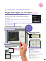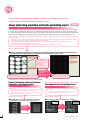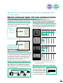
1
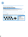
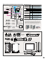
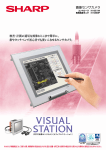
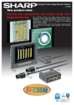
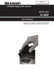
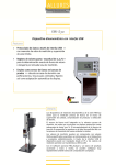
Image Sensor Cameras
Controller IV-S51M
LCD monitor IV-08MP
Image processing for various inspections and
measurements can be easily made with user-friendly
touch screen operated with finger or stylus pen.
Next-generation image sensor camera
“VISUAL STATION”
ISO-9001
certification
JQA-1385
Sharp Manufacturing Systems Co., Ltd.
Our headquarters has received
ISO14001 certification
(environmental management system).
VISUAL STATION is the next-generation
image sensor camera that pursues
usability, visibility, and comprehensibility.
Complete range of functions
from equipment selection to maintenance
Setting
startup
Operation
Analysis
Maintenance
Only Sharp can offer you complete range of functions
starting with equipment selection.
Inspections and measurements using an image sensor
camera used to require a lot of experience and time of an
Integrated
operator to select equipment and set up the system. Now,
As you like
Sharp s VISUAL STATION, the next generation image
Separated
sensor camera, can integrate all the experiences and
know-how of image processing experts into one unit. It
offers the complete range of functions of image
processing including operation and maintenance.
Controller
IV-S51M
LCD monitor
IV-08MP
Especially, new functions to support start set-up that used
to take up man hours and labor are also integrated in this
system. By simply following the displayed instruction and
directly entering parameters in touch screen with a finger
or a stylus pen, even a beginner can set up the camera
easily and quickly. VISUAL STATION eliminates the
deviation among individual operators in terms of the
inspection/measurement results, and contributes to
standardization and stabilization of
inspection/measurement results, reduction of man hours
and shortening of time.
1
Next-generation image sensor camera
“VISUAL STATION”
Setting
startup
You can directly enter your parameters in touch screen.
Screen view shows operation procedure at a glance.
Easy pen-touch entry and new menu system
Industry’s first
※
VISUAL STATION offers you easy LCD touch screen operation. By simply following the
displayed instruction, even a beginner can set up the camera easily and quickly. Newly
employed menu system can realize operationality and handiness better than ever.
It used to be・・・
○Troublesome and time consuming to enter the parameters and set-up items by
moving cursor with set-up key pad,
○Difficult for a beginner or a less-experienced operator to know how and what to
set up, and
○Hard to see the screen with the inspection screen view and the menu overlapped.
Conventional screen view
(poor visibility with mixed display)
With our VISUAL STATION...
●Even a beginner can start the operation without any
difficulty by simply following this flow system.
Easy-to-see screen view with a split
display screen for inspection and menu
You can see
what to start with,
end with and what
to set up at a glance.
* Essential items to set
up will be highlighted
in orange.
●Help function can quickly give
you the definition of unknown
word on the screen.
●New menu system helps you
select from inspection purpose.
SVGA monitor with
improved visibility
●Realized free-shape drawing in the
measuring area.
Industry’s first
※
Measuring area can
be freely and quickly
drawn with stylus
pen.
Measuring area can be designated
in detail by each dot by using stylus
pen or specifying numeric values.
Suitable for accurate depiction.
※ As of June 2003 for image sensor cameras
You can select the appropriate menu without
having image processing expertise.
This is suitable for・・・
■Existence of work and size inspection
● Inspection for missing dot of LCD, existence of debris
● Inspection for existence for flash of molded item
● Inspection for existence of connector pin
■The number of projected parts and the width, interval, etc.
of the alignment
● IC lead width inspection
● Inspection for intervals, number, and diameter of BGA solder ball
■Shape degree of match inspection
● Shape of ball bearing/gear
● Inclination/misalignment of labels and seals
■Workpiece counting
● Workpiece counting of confection before wrapping
● Inspection for missing capsule/tablet
2
Setting
startup
Extraction of appropriate binary processed image requires no
experience or technical knowledge of user.
Image processing procedure automatic generating expert
Industry’s first
※
(patent pending)
VISUAL STATION is equipped with Image processing procedure automatic generating expert developed based on the know-how of image
processing experts, and the analysis and collection of academic data. By simply entering the parameters according to the instruction on the
screen and draw round the inspecting area with stylus pen, processing procedure will be automatically generated and executed. Image will be
quickly extracted. Reducing the personal difference and shortening the time, this system improved efficiency and uniformity of the work.
It used to be・・・
○Difficult for a less-experienced operator to know what kind of image processing should be conducted in what
procedures in order to obtain an appropriate inspection image,
○Difficult to stabilize the quality since there were some deviations when setting up image processing
parameters among individual operators, and
○Uncertain and time consuming to set up correct parameters for image processing.
With our VISUAL STATION...
●Drawing around the inspecting area and entering inspection purpose and parameters will automatically
generate appropriate image processing procedure and execute binary processing.
Automatically
generate smoothing
●Binary processing
●Expansion
●Contraction
●Area filter, etc.
●
Draw around the area you wish to inspect and enter the
parameters according to the instruction on the screen.
Automatically
generates and
executes
appropriate image
processing.
The identified inspecting area
can be automatically extracted.
Automatically correct distortion of image. (Patent pending)
Camera inclination and lens distortion
automatic correction function
Correct focus position will be informed for clearer image.
Informing function of optimum focus
It used to be・・・
○Difficult to conduct stable image detection when the camera
was inclined and created distortion in the image, and
○Difficult to eliminate the errors caused by the lens distortion
depending on the inspected position.
It used to be・・・
○Relying on the individual operator s sense to focus, not
knowing whether it was the optimum focus.
With our VISUAL STATION...
With our VISUAL STATION...
●Automatically correct measurement error caused by
inspected position resulted from image distortion.
●Optimum focus can be confirmed from bar display.
Distortion of
the image will be
automatically
corrected.
Place the separately-sold reference plate for distortion correction under the camera,
and enter the correct scale distance, then execute.
Easy
focusing.
Turn the focus adjuster to the point at which the bar display shows the maximum
value.
3
※ As of June 2003 for image sensor cameras
Operation
Maintenance
High-quality IV assets are inherited, and S search and lighting control
are newly added.
High basic performances together with various maintenance functions
New algorism (S search) reinforces search function.
New algorism reinforces the functions of conventional gray
search (correlation for normalization). This system provides a
stable search even if the workpiece you wish to search is
(Patent pending)
partially hidden or chipped.
It used to be・・・
○Difficult to conduct
the stable search
unless the
workpiece was
perfectly visible
and captured.
High speed camera and partial image capture
function greatly reduce the inspection time.
VISUAL STATION can work with double-speed/quadruple-speed
cameras with progressive system CCD. Partial image capture
function speed up the image-capturing. And further reduction of
time can be possible by selecting from 4 modes to suite your
inspection/measurement purpose.
Whole image/full mode
Whole screen is captured by full line
IV-S51M + Standard camera
33.3ms
IV-S51M + High-speed camera
16.7ms
Whole image/half mode
Whole image is captured by half line
IV-S51M + High-speed camera
With our VISUAL STATION...
8.3ms
Partial image/full mode
This system provides a
stable search even if the
workpiece to search is
partially hidden or chipped.
Only the necessary part of the image is captured by full line
IV-S51M + Standard camera
16.7ms
IV-S51M + High-speed camera
Light level of the image is kept consistent by
light level automatic adjustment function.
8.3ms
(Notice)
Partial image/half mode
During the operation, the light volume on the workpiece used to
be inconsistent due to the changes of surrounding environment.
Inconsistency of the light volume could change the image s light
level, and hinder the stable inspection/measurement results.
VISUAL STATION uses light level automatic adjustment system
with illuminance monitoring function that provides the stable
screen image with the consistent light level.
Reliable maintenance with lighting control
VISUAL STATION is equipped with lighting control function.
When lighting power source for lighting control is used, generalpurpose serial interface can control ON/OFF of the lighting,
diagnose the light volume, and remotely control the lighting volume.
This function allows you to prevent from improper detection caused
by the lowered light volume.
※Lighting equipment can be controlled up to 4 units.
Extension connector
(RS-232C/RS-422)
Power source
for lighting
Camera 1
VISUAL STATION
Camera 2
Lighting 1
Only the necessary part of the image is captured by half line
IV-S51M + High-speed camera
4.2
ms
(Notice)
* Partial image is captured when 240 lines out of 480 lines are read.
* Standard cameras: IV-S30C1/IV-S30C2, high speed camera: IV-S30C3/IV-S30C4
* Full mode: odd /even lines are read, half mode: only odd lines are read.
(Notice) Image-capture time will differ depending on the position of partial image
(max. 0.4ms in the case above)
CCD trigger function requires no external sensor
With window for trigger set up, no
need for any external sensor even
for moving measurement. You can
select your trigger detection method
from binary processing, average light
level and gray search. Gray search
can be used for the workpieces for
which setting of the light range is tricky.
Direction of movement
CCD trigger
Lighting 2
●Contact our sales representative for the recommended lighting power source.
4
Analysis
High speed network that allows measured data and NG images to be
sent to upward personal computer
Equipped with Ethernet interface
VISUAL STATION is equipped with Ethernet interface that allows fast communication to upward personal computer.
You can see measured data and NG images at a personal computer which is located away from the inspection site.
Parameter setting support software (IV-S51SPM) can be installed at a personal computer.
It used to be・・・
○Time consuming to confirm the inspection status and conduct defect analysis, making it so difficult to provide the
prompt feedback.
With our VISUAL STATION...
●Measured data and NG images from multiple IV-S51Ms can be immediately sent to upward computer to reduce the
number of NG products.
Not for sale
※One to up to 63 IV-S51Ms can be connected to an upward computer.
VISUAL STATION
Inspection site (within factory)
Parameter setting support software
for IV-S51M series,
Personal computer
IV- S50SPM
This support software can be used for
management and analysis of inspection results.
Ethernet
IV-S50SPM
5
Contact our sales representative
for further details of this product.
●The set parameters can be read out.
●Equipped with data collecting function that forwards
measured data and NG images to upward computer.
●Forwarded screen view can be read out.
●Equipped with version upgrade function.
■System configuration of IV-S51M (When an IV monitor is not directly connected)
■IV-S51M Product line
Item name
USB mouse
USB trackball
For future extension
AC-DC
Converter
IV-S51M
●Parameter
setting
support software
IV-S50SPM
COM
General-purpose serial I/F
(RS232C/RS422)
system
selection expert
10BASE-T
100BASE-TX
LAN
(
ANALOG
RGB
)
Camera cable
Extension
connector
RS232C
RS422
(
CAMERA1
IV MONITOR
ONLY
CAMERA2
Camera
●Optical
USB
TERMINATOR
Parallel output
16 output
terminals
Standard
Micro
High speed
Micro, high speed
Camera lens
POWER
USB
Programmable
controller
Controller
Power source
unit for lighting
control
Connector
for LCD
monitor
Parallel input
(16 input terminals)
)
Lighting
IV LCD monitor
IV-S51M
IV-S30C1
IV-S30C2
IV-S30C3
IV-S30C4
IV-S20L16
IV-S30KC3
IV-S30KC5
IV-S30KC7
C mount
φ17 mm mount
C mount, 2×, 4×
φ17 mm mount, 2×, 4×
C mount lens with a 16 mm focal length
Cable for IV-S30C3/C1 camera, 3 m
Cable for IV-S30C3/C1 camera, 5 m
Cable for IV-S30C1 camera, 7 m
IV-08MP
8.4 TFT color LCD with a built-in I/F touch
panel (with stylus pen) for SVGA. The
monitor can be directly mounted to IV-S51M.
Screen image of display has 65,000 colors.
IV LCD monitor cable IV-S50MC2 Cable for IV LCD monitor (IV-08MP), 2m
Control/analysis of inspection data can be
Parameter setting support
IV-S50SPM set up on the Window s screen
software (not for sale)
(runs on Windows2000/XP/98).
Optical system selection
expert (not for sale)
◎Mixed
Analog
RGB
output
●Camera cable
IV-S30KC3 (3m)
IV-S30KC5 (5m)
IV-S30KC7(7m)
Camera lens Standard camera
IV-S20L16
IV-S30C1
SVGA monitor
cable for
IV LCD monitor (2m)
When directly connected
to the IV LCD monitor and
used as one unit, use the
connector for direct
mounting.
●Head
cable
IV-S30KC3 (3m)
IV-S30KC5 (5m)
−
Enter the inspection, purpose, viewing field,
and distance, then the recommended optical
system type will be displayed.
use of high-speed type and standard type is not supported.
VISUAL STATION offers the various installation options to suit
your installed location and environment. The monitor and the
controller can be connected directly or with monitor cable,
and the connector can be placed either vertically or horizontally.
●Monitor
●Camera
Camera lens High-speed camera
IV-S20L16
IV-S30C3
Specification or details
Monochrome 256 gray level, 64 object types,
Image processing procedure automatic generating
expert function (binary processing), hidden
workpiece search by new algorism (S search)
Personal
Computer
DC24V
AC100V
Model name
USB connector
(Use the accessorius angle brackets for vertical/horizontal placement.)
cable
(1m)
Camera Head
lens
●Camera cable
IV-S30KC3 (3m)
IV-S30KC5 (5m)
IV-S30KC7(7m)*
Micro camera
IV-S30C2
Micro, high-speed
camera
IV-S30C4
IV-08MP
(built-in touch panel)
*IV-S30C4 cannot be connected to IV-S30KC7 (7m).
■External dimension (Unit: mm)
◎Camera lens (IV-S20L16)
◎Standard camera (IV-S30C1/C3)
◎Camera cable ( IV- S30KC3/KC5/KC7 )
φ30
28.5∼34
5.5
30
3
Secure the brackets
into the M3 tap holes
(3 locations) with 20mm
of installation pitch.
φ
14.7
Side of camera
φ17
*1
5
20
32
32
7 *1 2-M3 Tap
3000
5000
7000
43
37
43
Movable range for focus adjustment
Head cable
Camera head
32
M15.5×0.5
φ16
Camera body
◎Micro camera (IV-S30C2/C4)
※
When lens is attached
φ17
3
8±0.1
22±0.1
35.6
1000
※6.8
IV-S30C2:44.7
IV-S30C4:50
6.5
30
◎IV LCD monitor (IV-08MP)
◎Controller (IV-S51M)
93
IV-S51M
POWER
USB
*2
COM
*2
USB
200
TERMINATOR
ANALOG
RGB
176.4
183.7
LAN
CAMERA1
CAMERA2
81
104
IV MONITOR
ONLY
126.4
136.4
7.3
242
14.55
42
*2 The controller can be attached at the backside using the brackets and screws (accessory).
6
Next-generation image sensor camera
“VISUAL STATION”
■Specifications of IV-S51M controller
Lighting adjustment
Adjustment of light volume
Image sampling system
Monochrome 256 gray level
Optical
system
Image memory
One screen for one captured image per camera
Light level automatic Monitoring illuminance→ shading diagnosis → optical system automatic adjustment
maintenance
(1. light volume, 2. shutter speed)
adjustment
No. of assignable object type
64 object types
No. of camera to be connected
Up to 2 cameras
Displaying measuring time, monitoring illuminance, switching language
between Japanese and English, running screen lock
Other functions
Image processing
Gray, binary conversion
function, and change image display (through/freeze)
Standard camera
33.3 ms
Image
capture time High speed camera
16.7 ms (full mode), 8.3 ms (half mode)
Image processing procedure
Object: position detection, position & attitude angle, size inspection,
workpiece count inspection, distance & angle measurement,
automatic generating expert
Gray search time
8ms (model: 64×64, search area: 256×256, when the speed is prioritized)
workpiece dimension measurement, and defect inspection
(binary processing)
142 ms (conditions: 360゜
, freeze, priority on speed, size 128×64, search area 512×480)
Rotation correction time
Gray search, edge detection precision
Sub-pixel
Auxiliary relays Internal auxiliary 1024 points (C0 ∼ C1023), system auxiliary 64 points (S0 ∼S63)
Micro PLC
Gray level change
Histogram widening
Timer
16 points (TM0 ∼ TM15), timer setting range (0.01 ∼ 9.99 seconds), (down counter)
section
Gray image
Smoothing (average/ center)
Counter
16 points (CN0 ∼ CN15), counter setting range (1 ∼ 999 seconds), (up counter)
pre-processing Noise elimination
Outline extraction Edge extraction (primary differentiation, secondary differentiation), horizontal edge, vertical edge
Input: 16 points (X0 ∼ X15), DC12/24V 7mA (DC 24V)
Parallel interface
Output: 16 points (Y0 ∼ Y15) DC12/24V 80mA (open corrector)
Binary threshold value
Fixed and threshold value correction (variation difference/variation rate)
IPU external
interface
Serial interface RS232C/RS422(2-wire/4-wire system), (2.4 ∼ 115.2kbps) upward calculator, PLC
Expansion, contraction,
Expansion→contraction→contraction → expansion,
and area filter
contraction → expansion → expansion → contraction, space filter
RS-232C/RS-422 (2-wire system only)
Extension terminal
Computer link
Positional correction method
X/Y correction, rotation correction
Compatible with SHARP, OMRON, Mitsubishi, and Yokokawa models.
Window shape
Rectangle, circle, oval, polygon, and free shape
Position detection
Object:1. single workpiece, 2. multiple work pieces can be processed simultaneously
Output: coordinate
Position &
attitude angle
Object: 1. single workpiece, 2. multiple workpieces can be processed simultaneously
Output: coordinate, angle
Shape degree of
match inspection
Object: 1. single workpiece, 2. multiple workpieces can be processed simultaneously
Output: Degree of match
Point sensor
Output: yes or no
Measurement Internal trigger
start input
External trigger
Power supply input
Parallel interface
Existence of work
Measurement: 1. no individual workpiece, 2. individual workpiece Output: area
Inspection
program and size inspection
Workpiece counting Object: 1. all the workpieces, 2. designated workpieces Output: number of object detected
No. of projected parts
and alignment
The number of projected parts, interval, width (point alignment)
Distance & angle
measurement
Object: 1. single workpiece, 2. multiple workpieces can be processed simultaneously
Output: distance (between 2 points/X coordinate/Y coordinate),
angle (3 points/2 points against vertical line/2 points against horizontal line)
Workpiece dimension
measurement
Output: number of workpiece, total area, area for each label, diameter
of the projection width, circumference length, main axes angle
Number of measurement
program
Maximum 8 measurements/type (measurement item 0 - camera 1,
measurement item 0 - camera 2, and measurement item 1 ∼ 6)
Arithmetic operation
Four basic operations (+,−, ×, ÷), root, absolute value,
TAN, ATAN, maximum, minimum, average, and total
NG image memory function
Calendar/timer
Maximum 128 images (8 whole scenes)
Year, month, day, hour, minute and second
Optical system Image adjustment 1
configuration
Image adjustment 2
setting
1. Image distortion diagnosis & compensation, 2. calibration
No. of effective pixels
Pixel shape
Shutter speed
Shutter
Method
Connector
Connection to controller
Operation ambient temperature/
humidity/atmosphere
External
dimensions
Power supply voltage/
power consumption
DC24V (±10%) 30W
Operation ambient temperature/
atmosphere
0 ∼ 45 ℃/35 ∼ 95% RH (non-condensing)
Storage ambient temperature/
atmosphere
- 20 ∼ 70 ℃/35 ∼ 95% RH (non-condensing)
External dimension/weight
81mm (W) × 125mm (D) × 175 mm (H) (protruding portions are not included),
approx. 1.5 kg
USB host
LAN
Image output
Operation input
1. Focus adjustment, 2. contrast adjustment
USB 1.1 specification, 2 channel
10/100 base-TX
VGA output port 1 point, IV LCD monitor output 1 point
Touch panel, and commercially available USB mouse
SVGA (800×600×24bpp) analog output
IV LCD monitor (800×600×18bpp) digital output
Image output
■Specifications of IV LCD monitor (IV-08MP) / IV LCD monitor cable (IV-S50MC2)
Standard
High speed
Micro
Micro, high speed
IV-S30C1
IV-S30C3
IV-S30C2
IV-S30C4
φ17 mm mount
C mount
Interline transmission method, monochrome CCD
Full pixel type, partial image scanning is available.
33.3 ms *1
16.7 ms (full mode), 8.3 ms (half mode) *1
1/3 inch
52 (horizontal) × 480 (vertical)
Tetragonal lattice
Settable between 1/30 ∼ 1/10,000 sec. (for each object type)
Random shutter
Round, 12-pin, male connector
Connection using custom camera cables
(IV-S30KC3: 3m, IV-S30KC5: 5m, and IV-S30KC7 *2: 7m)
30 (W) × 32 (H) × 40 mm(D)
Head section
Head cable
−
External dimension/weight
IV LCD monitor cable
1m
50 g (not including the lens)
8.4-inch, TFT liquid crystal panel, SVGA, custom I/F
65,000 colors
Resistance membrane type, Resolution 1024 × 1024
Reading the touch panel position
DC24V (±10%) 12W
0 ∼ 40 ℃/35 ∼ 90% RH (non-condensing)
-20 ∼ 60 ℃/35 ∼ 90% RH (non-condensing)
Equivalent to IP65
(The face of liquid panel only when mounting the main unit)
242 (W) × 42 (D) × 200 (H), approx. 1.0 kg
Connecting cable (2 m) for IV LCD monitor (IV-08MP)
■Operating environment of parameter setting support software (IV-S50SPM)
IV-S30C2: 30 (W) × 32 (H) × 50mm(D)
IV-S30C4: 30 (W) × 32 (H) × 44.7mm (D)
φ17 mm × 35.6mm
−
Screen size
Screen image of the display
Touch panel
RS232C Serial
LCD Power supply voltage/power consumption
panel Operation ambient temperature/atmosphere
Storage ambient temperature/atmosphere
Protection to the environment
0 ∼ 45 ℃/ 35 ∼ 85% (non-condensing), free from corrosive gases or dust
Camera body section
Weight
Control function
Number of control
Control port
Lighting
control
HMI External
interface
■Specifications of camera
Optical system Lens mount method
Method
Reading system
Picture Reading Standard
taking
time
High speed
element
Size
CCD trigger
Trigger input (parallel interface), serial trigger, and manual trigger (for testing)
+24V, 0V FG
Common for input: 1 point
Interrupt input (trigger) 1 point
Input 15 points
Common for output: 1point
READY 1 point
HALT output 1 point (interlocking with watchdog timer)
Output 16 points
Dimmer function, lamp ON/OFF (LED), shutter ON/OFF (halogen)
4 systems, 2 controls/1 system
Parallel I/F or RS-232C/RS-422
Operating system
Model
CPU
Memory
Hard disk
Mouse
Display
Printer
The environment where Windows 2000/XP/98 can be operated.
IBM PC/AT or compatible machines
Pentium 500 MHz or better
128 MB or more
30 MB or more free space
A mouse or pointing device compatible with the Windows 2000/XP/98 environment.
Resolution: 800 × 600 pixels (Recommended: 1024 × 768 dots), 65,000 colors
A printer compatible with the Windows 2000/XP/98 environment
IV-S30C2: approx. 125 g
(approx. 12g for head section)
IV-S30C4: approx. 140 g
(approx. 13g for head section)
■Specifications of camera lens (IV-S20L16)
Focal distance
Maximum f-stop
Aperture range
Focal range
Filter installation diameter
Mount system
Compatible cameras
16 mm
1.6
1.6 ∼ 16 close
50 mm ∼ ∞
M25.5, P = 0.75, U1
C mount
IV-S30C1/C3
*1 Variable by reading partial image.
*2 IV-S30C3/C4 can not be connected to IV-S30KC7(7m).
- Windows 2000/XP/98 are registered trademarks of the Microsoft Corporation, USA. - Company names, product names, and merchandise names described in this leaflet are the
trademarks or registered trademarks of each respective company. - The specifications may be changed without prior notice. The color of the actual product may vary from that shown
in this brochure. - Some models in this leaflet may be out of stock. Please contact your sales agent for selection of currently available models. - Images used in the leaflet may be
different from the images actually displayed on the monitor.
To use this device effectively and safely!
- Make sure to read the instruction manual before use. Make sure to supply the specified power and voltage.
SHARP MANUFACTURING SYSTEMS CORPORATION
4-1-33 Atobe Honmachi, Yao, Osaka, 581-8581, Japan
TEL: +81-729-91-0587 FAX: +81-729-91-0626
The details in this pamphlet were correct as of April 2004.
● Information about SHARP control equipments is available at our
web site http://sharp-world.com/sms/
SMS-068E 10803 O.1