1
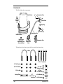
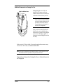
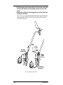
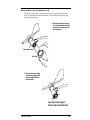
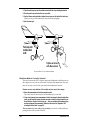
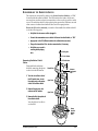
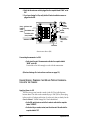
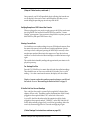
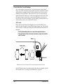
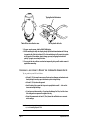
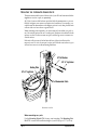
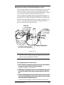
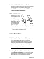
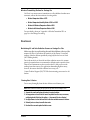
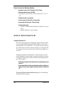
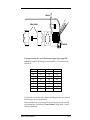
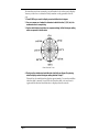
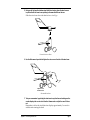
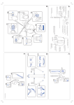
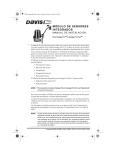
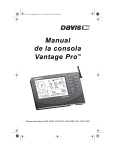
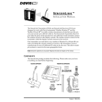
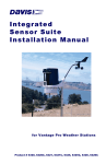
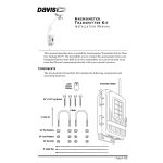
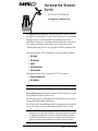
INTEGRATED SENSOR
SUITE
INSTALLATION MANUAL
For Vantage ProTM or Vantage Pro PlusTM
The Integrated Sensor Suite (ISS) collects several types of weather readings
for display at your Vantage ProTM console. The data is sent to the console either
through a cable or by wireless transmission, depending on the version.
With Wireless Vantage ProTM, the Integrated Sensor Suite (ISS) can be used as
one of eight sensor stations transmitting to your console/receiver(s). See
“Additional Mounting Options” and “Appendix A: Wireless Transmitter IDs”.
The Integrated Sensor Suite for Vantage ProTM measures weather conditions:
✦ Wind Speed
✦ Wind Direction
✦ Rainfall
✦ Outside Temperature
✦ Outside Humidity
The Integrated Sensor Suite for Vantage Pro PlusTM also measures:
✦ Ultraviolet Radiation (UV)
✦ Solar Radiation
Note: To upgrade a Vantage Pro system to Vantage Pro Plus, see “Appendix B: Optional Accessories”.
For mounting purposes, the Integrated Sensor Suite (ISS) consists of two sides:
the anemometer and the rain collector side.
The rain collector side is a white plastic shelf with the black rain collector cone
on top and the white radiation shield below.
The two sides can be mounted either together on a single pole (see illustration at
the top of this page), or separately. The anemometer has 40' (12 m) of cable.
Note: When both sides of the ISS are mounted together with the anemometer arm pointing north, the
solar panel on the rain collector side is facing south. In the Northern Hemisphere, this positions
the solar panel for optimal exposure to the sun. (In the Southern Hemisphere, you will need
to position the solar panel facing north for optimal sun exposure. When mounting both sides
together, this means pointing the anemometer arm south and re-orienting the wind vane.)
Product # 6150, 6150C, 6160, 6160C
C OMPONENTS
The ISS includes these components:
Rain Collector
Anemometer Vane
Solar
Panel
(wireless
models
only)
Control Head
Drip Ring
Wind Cups
Anemometer Arm
Radiation Shield
Debris Screen
(place inside
Rain Collector Cone
after installation)
40' (12.2 m)
Anemometer
Cable
Anemometer Base
The hardware shown here is provided for assembly and mounting.
U-Bolts
1/4" x 3" Lag Screws
1/4" Flat Washers
#4 x 1-1/8"
Machine Screw
1/4" Lock Washers
1/4" Hex Nuts
Backing Plate
#4 Tooth
Lock Washer
.05"
Allen Wrench
#4 Flat Washer
#4-40 Hex Nut
Page 2
3-Volt
Lithium
Battery
(wireless
models
only)
Integrated Sensor Suite
Additional Components on Vantage Pro Plus
UV and Solar Radiation Sensors
Vantage Pro Plus also includes an
ultraviolet (UV) sensor and a solar
radiation sensor. These two sensors are
on the rain collector side of your ISS.
Note: Please make every effort when handling your
ISS not to touch the small white diffusers on
top of the UV and solar radiation sensors. Oil
from the skin will reduce their sensitivity.
Clean the diffusers using ethyl alcohol on a
soft cloth (NOT rubbing alcohol).
Once you have mounted the ISS in its
final location, use the bubble level on
each sensor as a guide to verify that the
sensor is level. (To adjust, tighten or
loosen the screws holding the sensor on
the shelf.)
Each sensor has 3' (0.9 m) of cable. If you need to position the sun sensors away
from the rain collector side, use extension cables #7876 .
Note: Not all cables are compatible with your Vantage Pro system. To be sure they will work, order
Davis extension cables from your dealer or directly from Davis Instruments.
To upgrade your Vantage Pro to Vantage Pro Plus, see “Optional Sensors for
ISS” on page 28.
Components
Page 3
T ABLE
OF
C ONTENTS
Components................................................................................................ 2
Tools for Setup............................................................................................ 5
Preparing the Anemometer....................................................................... 5
Disassembling the Radiation Shield........................................................... 9
Cabled Version: Powering the ISS and Testing Communication.............. 10
Wireless Version: Powering the ISS and Testing Communication............ 12
Reassembling the Radiation Shield............................................................ 15
Preparing the Rain Collector..................................................................... 15
Choosing a Location to Mount the Integrated Sensor Suite.................... 16
Mounting the Integrated Sensor Suite..................................................... 18
A Note on Securing Cables....................................................................... 22
Additional Mounting Options.................................................................... 22
Maintenance............................................................................................... 23
Contacting Davis Instruments................................................................... 25
Weather Variable Update Intervals.......................................................... 25
Specifications for Cabled Version.............................................................. 25
Specifications for Wireless Version........................................................... 26
Appendix A: Wireless Transmitter IDs..................................................... 26
Appendix B: Optional Accessories............................................................ 28
Appendix C: Re-orienting the Wind Vane................................................. 29
Page 4
Integrated Sensor Suite
T OOLS
FOR
S ETUP
✦ Small Phillips-head screwdriver
✦ Scissors or wire-cutters
✦ Adjustable wrench or 7/16" wrench
✦ Compass or local area map
✦ Ballpoint pen or paper clip (small pointed object of some kind)
✦ Drill and 3/16" (5 mm) drill bit (if mounting on a vertical surface)
Before Going Outside...
Before mounting the Integrated Sensor Suite, you will need to prepare sensors, apply power, and test the connection between your ISS and the Vantage
Pro console. You may want to stay inside at a well-lit working table until ready
for “Choosing a Location to Mount the Integrated Sensor Suite” on page 16.
For ease of installation, please follow the steps in the order they are presented in the manual. (Each step builds on tasks completed in previous steps.)
P REPARING
THE
A NEMOMETER
The anemometer measures wind direction and speed. The wind vane is
already attached to the anemometer arm, but you will need to install the wind
cups and attach the arm to the base.
Please locate the following parts to prepare the anemometer:
✦ Anemometer arm (wind vane and cable already attached)
✦ Anemometer base
✦ Wind cups
✦ Drip ring
✦ Allen wrench (0.05")
✦ #4 machine screw, #4 tooth-lock washer, #4 flat washer, #4 hex nut
Attaching Anemometer Arm to Base
1. Insert the anemometer arm into the base, sliding the cable through the notch in the
base as shown in illustration on the next page.
Be sure to line up the small hole in the arm with the holes in the base.
2. Insert the machine screw through the holes in the base and arm.
Tools for Setup
Page 5
3. Slide the flat washer, tooth-lock washer and hex nut onto the machine screw. Tighten
the hex nut while holding the screw with a Phillips screwdriver to prevent it from
turning.
4. Press the sensor cable firmly into the zig-zagging channel in the base, taking up any
slack between arm and base.
Make sure that you press the anemometer cable down into the channel as
much as possible so that the U-bolt used for mounting will not pinch or
cause wear on the cable.
#4-40
Hex Nut
#4 Tooth
Lock Washer
Slide cable
through notch
#4 Flat
Washer
#4 x 1-1/8"
Machine Screw
Route cable firmly
into channel
ATTACHING ANEMOMETER ARM TO BASE
Page 6
Integrated Sensor Suite
Attaching Wind Cups to Anemometer Arm
The wind vane is situated at the end of the arm, on top of the anemometer
head. Underneath the anemometer head you will attach a black plastic drip
ring and the wind cups.
1. Slide the black plastic drip ring
onto the anemometer head. Gently push the drip ring up until it
clicks into place.
Anemometer Head
Drip Ring
2. Make sure the lower edge of
the drip ring is aligned with
the lower edge of the anemometer head.
Lower edge of drip ring aligned
with lower edge of anemometer head
Preparing the Anemometer
Page 7
3. Push the wind cups up onto the stainless steel shaft that is protruding downward.
4. Slide the wind cups up the shaft as far as possible.
5. Use the Allen wrench provided to tighten the set screw on the side of the wind cups.
When you let go of the wind cups, they should drop slightly.
6. Spin the wind cups.
Push cups onto
stainless steel
shaft
Tighten set screw
with Allen wrench
ATTACHING WIND CUPS TO ANEMOMETER ARM
Wind Vane Must Be Correctly Oriented
The wind vane rotates 360° to display current and dominant wind directions on
the compass rose of your console screen. To display this information, the vane
must be correctly oriented when you mount the anemometer outside.
Ensure correct orientation of the wind vane in one of two ways:
1. Mount the anemometer so that the arm points north.
The wind vane will be ready for use immediately if you do this.
2. (If you want to mount your anemometer so that it aims toward a direction other than
north, you will need to remove the wind vane and re-attach it aiming toward the preferred direction. But don’t do this just yet — after you complete the remaining preparations and mount the anemometer, follow the instructions in “Appendix C: Reorienting the Wind Vane” on page 29.)
The anemometer is now ready to be mounted, you can set it aside while preparing the rain collector side of the ISS.
Page 8
Integrated Sensor Suite
D ISASSEMBLING
THE
R ADIATION S HIELD
The sensors are connected by cables to the Sensor Interface Module, or “SIM”,
located inside the radiation shield. The SIM contains electronics which measure and store weather values for transmission to the console via cable or radio
waves. The radiation shield’s white plastic plates protect the SIM from sun and
other sources of radiated and reflected heat, and from precipitation.
Before the ISS can be mounted, you need to disassemble the radiation shield
to do the following tasks:
✦ Verify that the rain sensor cable is plugged in
✦ Connect the anemometer sensor cable to the Sensor Interface Module, or “SIM”
✦ Apply power to the ISS (different methods for cabled/wireless versions)
✦ Change the transmitter ID for wireless communication, if necessary
✦ Verify that your console is
receiving and displaying
data
#8 Wing Nut
#8 Lock Washer
Removing Radiation Shield
Plates
#8 Flat Washer
Disassemble the radiation
shield by removing the plates
as shown in the illustration.
Closed Plate
1. Turn the rain collector side of
the ISS upside down. Locate
three wing nuts on the underside of the radiation shield.
Open Plate
2. Remove the wing nuts, lock
washers and flat washers.
Antenna
deployment
hole
Open Plate
3. Remove the first three plates of
the radiation shield.
You should now be able to
see the SIM.
Sensor
Interface
Module
(SIM)
Disassembling the Radiation Shield
Page 9
4. Verify that the rain sensor cable is plugged into the receptacle labeled “RAIN” on the
SIM.
5. If you have a Vantage Pro Plus, verify that the UV and solar radiation sensors are
plugged into the SIM.
UV Sensor Cable
UV
Solar Radiation Cable
SUN
(factory
installed
on Plus
models)
3-Volt
Lithium
Battery
(wireless
versions only)
Rain Collector Cable
(factory installed)
Anemometer Cable
CONSOLE
RAIN WIND
AC Power
(optional)
Console Cable
(cabled versions
only)
DIP Switches
SENSOR INTERFACE MODULE (SIM)
Connecting Anemometer to SIM
✦ Gently insert the end of the anemometer cable into the receptacle labeled
“WIND” on the SIM.
Unwind the coil of cable enough to work with the anemometer.
(Wireless Vantage Pro instructions continue on page 12.)
C ABLED V ERSION : P OWERING THE
TION WITH THE C ONSOLE
ISS
AND
T ESTING C OMMUNICA-
Applying Power to ISS
The ISS receives power from the console via the 40' (12 m) cable that runs
between them. This cable can be extended by up to 1000' (305 m). Please plug
in the console’s AC adapter at this time, if you haven’t done so already. See the
Console Manual: “Cabled Vantage Pro Console Installation.”
✦ On the SIM, gently insert one end of the 4-conductor cable into the receptacle
labeled “CONSOLE”.
✦ On the back of your console/receiver, insert the other end of the cable into the
receptacle labeled “ISS”.
Page 10
Integrated Sensor Suite
(Setup of Cabled version, continued...)
Once powered, your ISS will immediately begin collecting data from the sensors for display at the console. Data is sent through the cable that you connected during the preceding step in order to power the ISS.
Verifying Reception of ISS Data at the Console
When you plugged in your console to apply power to the ISS, the console went
into Setup Mode. Press and hold down the DONE key until the “Current
Weather” screen appears. (You can return to Setup Mode at any time: press and
hold DONE key then press DOWN arrow key.)
Viewing Current Data
You should now see weather readings from your ISS displayed onscreen. Near
the center of the screen, look for inside and outside temperatures. Spin the
wind cups to check wind speed, pressing the WIND key if necessary to alternate between speed and direction in the compass rose. Turn the wind vane,
and allow 5 seconds for the wind direction display to stabilize before moving it
again.
The outside relative humidity reading takes approximately one minute to display after power-up.
For Vantage Pro Plus
Press the UV/SOLAR key for current ultraviolet and solar radiation readings.
These should be zero or close to zero while the ISS is inside. Zero is a valid
reading — if no data comes from the sensors, the display will show dashes.
Display of current weather data confirms connection between your ISS and
the console. Go on to “Reassembling the Radiation Shield” on page 15.
If You Do Not See Current Readings
First, verify that the console is powered by the supplied AC adapter (other
adapters will not work). Then make sure that the transmission cable is firmly
plugged into the receptacle labeled “ISS” on the back of the console.
At your ISS, check that the other end of the transmission cable is firmly
plugged into the receptacle marked “CONSOLE” on the SIM. Verify that all
sensor cables are firmly plugged in. If you still don’t get readings, reboot the
console by disconnecting power for 30 seconds and applying it again.
(Cabled Vantage Pro instructions continue on page 15.)
Cabled Version: Powering the ISS and Testing Communication with the Console
Page 11
W IRELESS V ERSION : P OWERING
TION WITH THE C ONSOLE
THE
ISS
AND
T ESTING C OMMUNICA-
Applying Power to ISS
Insert the 3-volt lithium battery into the SIM.
✦ Insert the battery into the battery holder, matching the “+” sign on the battery
with the “+” sign on the SIM.
The solar power components store electricity inside the SIM for use at night.
When this energy is depleted, the ISS uses power from the battery.
Transmitter IDs
Once powered, your ISS will immediately begin transmitting sensor data for
display at the console/receiver. Transmitter IDs allow Vantage ProTM or
Weather EchoTM consoles to identify signals from up to eight different wireless
transmitting stations in the field.
The factory default transmitter ID for the ISS is ‘1’
You probably do NOT need to change the transmitter ID. The default transmitter ID for ISS is ‘1’. Your console/receiver will find the ISS automatically.
Change the transmitter ID for your ISS if the following is true:
✦ Another Davis Instruments wireless weather station is operating nearby, on trans-
mitter ID ‘1’.
The transmitter ID for your ISS is changed by adjusting small DIP switches
located on the SIM, while the radiation shield is open. See “Appendix A:
Wireless Transmitter IDs”.
Page 12
Integrated Sensor Suite
(Setup of Wireless version, continued...)
Verifying Reception of ISS Data at the Console
Install three C batteries to power-up your console/receiver, if you haven’t done
so already. Details in the Console Manual: “Wireless Vantage Pro Console
Installation.” If it is already powered but not in Setup Mode, press and hold the
DONE key then press the DOWN arrow key.
When powered-up, the console will go into Setup Mode – Screen 1: Transmitters. You should see the words: “RECEIVING FROM...” and “STATION NO.”
followed by the transmitter IDs that your console detects.
The number ‘1’ shows that your ISS is being detected, unless you changed its
ID with the DIP switches. (If you did, change it at the console also. Please see
the Console Manual: “Setup Mode – Screen 2: Selecting Transmitters”).
If you see the number ‘1’, press and hold down the DONE key to view the data
onscreen. If you do not, skip down to “TEST mode” below.
Viewing Current Data
You should now see weather readings from your ISS displayed onscreen. Near
the center of the screen, look for inside and outside temperatures. Spin the
wind cups to check wind speed, pressing the WIND key if necessary to alternate between speed and direction in the compass rose. Turn the wind vane,
and allow 5 seconds for the wind direction display to stabilize before moving it
again.
The outside relative humidity reading takes approximately one minute to display after power-up.
For Vantage Pro Plus
Press the UV/SOLAR key for current ultraviolet and solar radiation readings.
These should be zero or close to zero while the ISS is inside. Zero is a valid
reading — if no data comes from the sensors, the display will show only
dashes.
Display of current weather data confirms connection between your ISS and
the console. Go on to “Reassembling the Radiation Shield” on page 15.
Wireless Version: Powering the ISS and Testing Communication with the Console
Page 13
If You Do Not See Current Readings
First, verify that the console/receiver is powered and is not in Setup Mode.
Then, on your ISS, ensure that all sensor cables are firmly connected to the SIM
and the battery is properly installed. Walk around the room with the console,
standing for a few moments in various locations to see if you are picking up
signals from the ISS. There is an ‘X’ on the lower right hand corner of the screen
that appears when a transmission is received and disappears when the next
one is received. If you do not see the ‘X’ slowly blinking, no matter where you
stand with the console, put your ISS in TEST mode.
TEST mode
DIP switch #4 on the SIM (see the diagram below) is the TEST DIP switch.
Switch it to the ON position, using a ball-point pen or paper clip. This puts the
ISS in Test Mode. An LED indicator light on the SIM will flash each time the ISS
transmits:
✦ The LED will immediately flash once to show that the light itself functions.
✦ Then it will flash each time the transmitter broadcasts a signal, which should be
every 2.5 seconds.
Antenna
Battery Holder
ON
1
2
3
4
DIP Switch #4
DIP SWITCHES IN TOP-RIGHT CORNER OF SIM (ILLUSTRATION HAS BEEN ENLARGED FOR CLARITY)
If the LED flashes only once and then remains dark, there is a problem with the
ISS transmitter. See “Contacting Davis Instruments” on page 25.
Page 14
Integrated Sensor Suite
If the LED flashes repeatedly but your console isn’t picking up a signal anywhere in the room, it could be related to one of the following causes:
1. You changed the transmitter ID on the ISS but didn’t change it at the console/receiver.
2. Reception is being disrupted by RF (radio frequency) interference.
Interference has to be strong to prevent the console from receiving a signal
while in the same room as the ISS! In high-interference environments, it may
be preferable to install the Cabled Vantage Pro.
3. There is a problem with the console/receiver.
See “Contacting Davis Instruments” on page 25.
Note: Remember to set the Test DIP switch to OFF when you’re finished testing wireless transmission. If it is left ON, the blinking LED will reduce battery life significantly.
R EASSEMBLING
THE
R ADIATION S HIELD
1. Slide the two open plates over the threaded studs.
2. Slide the single closed plate back over the threaded studs.
On wireless version, ease the antenna through the antenna deployment hole.
3. Place the flat washers, lock washers and plastic wing nuts over the studs.
4. Finger-tighten the wing nuts until they hold the radiation shield plates firmly in place.
P REPARING
THE
R AIN C OLLECTOR
See the illustration on the following page.
1. Remove the rain collector cone from its base by rotating the cone counter-clockwise
until its latches line up with openings in the base and you can lift it off. (The cone fits
in the base tightly and may require extra pressure to remove it the first time. Tip:
steady the base between your knees.)
On Vantage Pro Plus, the UV and solar radiation sensor cables are routed
through the base of the rain collector. Please make sure they do not get
moved. Use care to ensure they do not interfere with the tipping bucket
mechanism or with your ability to get the cone latched back onto the base.
2. Carefully cut and remove the plastic cable tie (usually black in color) that holds the
two-sided tipping bucket mechanism in place during shipping.
Reassembling the Radiation Shield
Page 15
Tipping Bucket Mechanism
Twist off the rain collector cone.
Cut the plastic cable tie.
3. On your console screen, look for DAILY RAIN display.
4. While watching the daily rain display, slowly tip the bucket mechanism until it drops
to opposite side. Each tip indicates 0.01" of rain and takes up to 10 seconds to register
at the console. If the number doesn’t change, you may be tipping the bucket too
quickly. Try again, more slowly this time.
5. You can put the rain collector cone back on temporarily, but you will need to remove it
again before mounting.
C HOOSING
A
L OCATION
TO
M OUNT
THE I NTEGRATED
S ENSOR S UITE
Try to position your ISS as follows:
✦ At least 5' (1.5 m) away from sources of heat such as chimneys and exhaust vents.
Avoid placing it near any space that heats up a lot during the day.
✦ At least 5' (1.5 m) above the ground.
✦ Avoid locating it in an area that is prone to precipitation runoff — look out for
trees and nearby buildings.
✦ If you have a wireless model, or if you have the Vantage Pro Plus, look for a loca-
tion with good sun exposure throughout the day.
✦ Mount the anemometer at least 4' (1.2 m) above the roofline for more accurate
wind readings.
Note: For roof mounting, and for ease of installation in other locations, we recommend using the
optional Mounting Tripod #7716.
Page 16
Integrated Sensor Suite
Range of Wireless Transmission
The range of wireless transmission depends on many factors. For the best
reception, position your ISS and console/receiver as close together as possible.
Range is up to 800' (250 m) in the line of sight, under optimal conditions. Typical range under most conditions is 150' to 500' (45 to 150 m), but this may be
reduced by walls, ceilings, trees, or foliage. Radio-frequency interference (RF)
can also reduce transmission distance. Cordless phones and ham radios are
common examples of RF interference.
A metal roof or other large metal structure can interfere with the signal (aluminum siding, a furnace with metal ducts, and your refrigerator are examples).
Sometimes transmission between wireless units is obscured by something you
cannot identify, or by some obstacle that you can’t work around. If necessary,
consider using Wireless Repeater #7624 or #7625 to strengthen the signal or
increase the distance between your ISS and the console/receiver.
Testing Wireless Transmission at Proposed ISS Location
Now that you’ve found a suitable place for your wireless ISS, it is very important to test reception from that location before permanently mounting it there.
Place both sides of your ISS at the intended mounting site, or have someone
hold them there, so you can walk around with the console/receiver for a few
minutes. (If you plan to mount the two sides of the ISS apart from each other,
test transmission from the proposed location of the rain collector side, since it
contains the transmitter.)
For the sake of example, let’s say you are installing your Wireless Vantage Pro
at your house, with the ISS mounted on a fence at the back of the property.
With the ISS up on the fence temporarily, walk through your house with the
console, testing reception in various rooms. There is an ‘X’ on the lower right
hand corner of the screen that comes on when a transmission is received and
goes off again when the next one is received. Rotating the antenna on the console may help to improve reception. (See also the discussion in the Console
Manual on the use of the GAIN feature.)
Test wireless reception anywhere you might want to use or mount your console/receiver now or in the future. Take your time. If you aren’t picking up a
strong signal where you intend to place your console, better to move the ISS
now than after it has been mounted. Experiment.
If you have irregular terrain in the area, it may interfere with the signal. For
example, if the ISS is mounted downhill from the console/receiver, the ground
may block a wide angle of the transmitted signal.
When mounting the ISS on your roof
Be aware the signal may be weak directly underneath the rain collector side.
Please be sure to test reception anywhere you might want to view or mount
your console/receiver.
Choosing a Location to Mount the Integrated Sensor Suite
Page 17
M OUNTING
THE I NTEGRATED
S ENSOR S UITE
The anemometer and the rain collector side of your ISS can be mounted either
together as a unit on a pole, or separately.
40' (12 m) of sensor cable has been provided with the anemometer so you can
flexibly configure your system to monitor wind conditions. For example, you
could mount the anemometer at the highest point of a roof, then place the rain
collector side on a fence closer to ground level.
When mounting sides separately, you can mount each one either on a pole or
on a flat vertical surface such as a wooden post. Hardware is included for both
options: use the U-bolts to mount on a pole, and the lag screws to mount on a
vertical surface.
If the rain collector cone is latched into the base of the rain collector side,
remove it now. If it isn’t, do not put it on just yet! With the cone in the way you
will not have room to use the mounting hardware.
1/4" Flat Washers
1/4" x 3" Lag Screws
Backing Plate
1/4" x 3" Lag Screws
40' of Anemometer Cable
MOUNTING ON A POST
When mounting on a pole
Use the Mounting Tripod #7716 for easy roof-mounting. The Mounting Pole
Kit #7717 can raise the installation height of your ISS by up to 37.5" (0.95 m).
Page 18
Integrated Sensor Suite
Mounting ISS as a Single Unit (Both Sides Together on a Pole)
Once you loosely mount the two sides of your ISS together on a pole, you’ll be
able to swivel the unit to the correct direction and then tighten the hex nuts.
You will also be able to slide it vertically to the desired height. Take a compass
or local area map to help you determine which direction is north.
It is very important to remember, when mounting both sides together, that
whichever side of your ISS is mounted first, the U-bolt from the opposite side
ALSO must be placed around the pole before you tighten anything. (If it is not,
there is no way to slide it in later.) In each side’s mounting base, there is a
groove to accommodate the other side’s U-bolt.
1/4" Hex Nut
1/4" Lock Washer
Backing Plate
1/4" Flat Washer
1/4" Lock Washer
1/4" Hex Nut
U-Bolts
Rain Collector Side's Mounting Base
Anemometer's Mounting Base
MOUNTING ON A POLE
Note: With the supplied U-bolts, the ISS can be mounted on a pole having an outside diameter ranging
from 1-1/4" to 1-3/4" (32 – 44mm). Larger U-bolts (not supplied) can be used to mount to a
pole with a maximum outside diameter of 2-1/2" (64mm).
Start by mounting the rain collector side
1. Place the U-bolt for the anemometer around the pole so that its round end will fit in
the top groove of the rain collector side’s plastic mounting base.
The groove is right above two large holes.
2. While holding the mounting base of the rain collector side against the pole, place the
two ends of the remaining U-bolt around the pole and through the two holes in the
base.
3. Slide the metal backing plate over the bolt ends as they stick out over the rain collector base. Secure the backing plate with a lock washer and hex nut on each of the bolt
ends as shown above. Do not tighten the nuts yet.
Leave the nuts loose enough to swivel the rain collector side on the pole.
Mounting the Integrated Sensor Suite
Page 19
Please remember to mount your ISS so the anemometer arm is extending
toward the north. (Otherwise, you will need to re-orient the wind vane. See
“Appendix C: Re-orienting the Wind Vane” on page 29.)
Note: In the Northern Hemisphere, when the anemometer arm is pointing north, the solar panel will
be facing south for maximum sun exposure. If you are in the Southern Hemisphere, in addition
to pointing the anemometer north, the solar panel should probably also face north, for maximum
sun exposure (unless you are in the tropics, where it doesn’t matter as much). Either mount the
two sides separately, each facing north, or mount the ISS as a single unit with solar panel facing
north and re-orient your wind vane to south. See “Appendix C: Re-orienting the Wind Vane”.
Continue by mounting the anemometer and securing both sides
1. The two ends of the anemometer’s U-bolt should now be pointing away from the
mounted rain collector side. Slide the anemometer’s mounting base over the protruding bolt ends. Place a flat washer, a lock washer and a hex nut on each of the bolt ends
as shown above. Do not tighten the nuts yet.
Now you can raise the entire unit to the desired height on the pole, and
swivel it so the anemometer arm is pointing north.
2. Using an adjustable wrench or 7/16" wrench, tighten all four hex nuts until the ISS is
firmly fastened on the pole.
3. Re-attach the rain collector cone.
Set the cone back on the base so its latches slide downward into the latch
openings on the base. Rotate cone clockwise.
4. Place the debris screen (shown in the illustration on page 2) inside the cone, “feetdown” over the funnel hole.
Mounting Rain Collector Side on a Pole by Itself
See the illustration on page 19.
1. While holding the mounting base against the pole, place the two ends of a U-bolt
around the pole and through the two holes in the base.
2. Slide the metal backing plate over the bolt ends as they stick out toward the rain collector cone. Secure the backing plate with a washer, a lock washer, and a hex nut on
each of the bolt ends. Do not tighten the nuts yet.
For wireless version, swivel the rain collector side so the solar panel is facing
south (in the Northern Hemisphere), or north (in the Southern Hemisphere).
3. Using an adjustable wrench or 7/16" wrench, tighten the nuts.
4. Re-attach the rain collector cone.
Set the cone back on the base so its latches slide downward into the latch
openings on the base. Rotate cone clockwise.
5. Place the debris screen (shown in the illustration on page 2) inside the cone, “feetdown” over the funnel hole.
Page 20
Integrated Sensor Suite
Mounting Anemometer on a Pole by Itself
See the illustration on page 19.
1. While holding the mounting base against the pole, place a U-bolt around the pole and
through the two holes in the base.
2. Place a flat washer, a lock washer and a hex nut on each of the bolt ends.
3. Swivel the anemometer until the arm is pointing north.
If the anemometer arm is not pointing north, go to “Appendix C: Re-orienting the Wind Vane” on page 29 after tightening the nuts.
4. Using an adjustable wrench or 7/16" wrench, tighten the nuts.
Mounting Rain Collector Side on a Vertical Surface
See the illustration on page 18.
1. With a 3/16" (5 mm) drill bit, drill two holes approximately 2-1/8" (54 mm) apart. Use a
carpenter’s level to ensure the holes will be level.
Use the metal backing plate as your guide when marking the holes.
2. Insert the 1/4" x 3" lag screws through the metal backing plate and the holes in the
mounting base into the post.
3. Using an adjustable wrench or 7/16" wrench, tighten the lag screws.
4. Re-attach the rain collector cone.
Set the cone back on the base so its latches slide downward into the latch
openings on the base. Rotate cone clockwise.
5. Place the debris screen (shown in the illustration on page 2) inside the cone, “feetdown” over the funnel hole.
Mounting Anemometer on a Vertical Surface
See the illustration on page 18.
1. With a 3/16" (5 mm) drill bit, drill two holes approximately 2-1/8" (54 mm) apart. Use a
carpenter’s level to ensure the holes will be level.
2. Insert the 1/4" x 3" lag screws through the flat washers and the holes in the mounting
base into the post.
3. Using an adjustable wrench or 7/16" wrench, tighten the lag screws.
If the anemometer arm is not pointing north, follow the instructions in
“Appendix C: Re-orienting the Wind Vane” on page 29.
Mounting the Integrated Sensor Suite
Page 21
Clearing the Data Collected While You Were Testing Reception
Now that your ISS is mounted outside, you may want to clear out the data that
was stored in the console while it was indoors. To do an “all-clear”,
1. Press the WIND key so the graph icon appears underneath “Wind” in top-left corner.
2. Press the 2ND key, then press and hold the CLEAR key.
A N OTE
ON
S ECURING C ABLES
To prevent fraying or cutting of
cables, secure them so they will
not whip about in the wind —
Secure a cable to a metal pole
by wrapping electrical tape
around them both. Make sure
cables are secure by placing
clips or ties approximately
every 3 – 5' (1 – 1.6 m).
Cable Tie
Cable Clip
When mounting the anemometer near the rain collector side, tuck the coil of
cable between the rain collector cone and mounting base.
Note: Do not use metal staples or a staple gun to secure cables. Metal staples—especially when
installed with a staple gun—have a tendency to cut the cables.
A DDITIONAL M OUNTING O PTIONS
Cabled Vantage Pro: Mounting the Anemometer Farther Away
If you would like to locate the anemometer more than forty feet from the rain
collector side, use extension cables #7876 from Davis Instruments.
Please be aware that maximum wind speed reading decreases as the total
length of cable from the anemometer to the ISS increases. If this distance is
greater than 240', maximum wind speed may be less than 100 mph.
Note: Not all cables are compatible with your Vantage Pro system. To be sure they will work, order
extension cables from your dealer or directly from Davis Instruments.
Wireless Vantage Pro: Mounting the Anemometer Farther Away
Use the Anemometer Transmitter Kit #6330 to add a transmitter to your anemometer. Then it will function as a transmitter station sending wind data
directly to the console/receiver, instead of transmitting via the ISS.
Page 22
Integrated Sensor Suite
Wireless Transmitting Stations for Vantage Pro
Use Davis’ new remote sensor/transmitters to collect additional weather measurements, without the inconvenience of routing cables:
✦ Wireless Temperature Station #6370
✦ Wireless Temperature/Humidity Station #6380 or #6385
✦ Wireless Soil Moisture/Temperature Station #6361
✦ Wireless Leaf Wetness/Temperature Station #6341
For more details, please see “Appendix A: Wireless Transmitter IDs” on
page 26, or the Vantage Pro catalog.
M AINTENANCE
Maintaining UV and Solar Radiation Sensors on Vantage Pro Plus
Make every effort to avoid touching the small white diffusers at the top of the
sensors. Any skin oil will reduce the sensitivity of the sensors. For accurate
readings, clean the diffusers periodically using ethyl alcohol on a soft cloth
(NOT rubbing alcohol).
Due to the sensitivity of ultraviolet and solar radiation sensors it is common
practice for manufacturers to recommend re-calibration after a period of time.
Here at Davis Instruments we have seen less than 2% drift per year on the
readings from these sensors. For applications demanding higher accuracy,
however, the sensors should be calibrated once every year.
Contact Technical Support (510) 732-7814 about returning your sensor for calibration.
Cleaning Rain Collector
For accuracy, thoroughly clean the rain collector several times a year.
Note: Please be aware that cleaning the tipping bucket may cause false rain readings to occur.
1. Separate the cone from the base by turning it counter-clockwise.
2. Use soapy water and a soft cloth to remove any debris from the cone, cone screen,
and tipping bucket. Watch out for spiders — they seem to like rain collectors!
3. Use pipe cleaners to clear the funnel hole in the cone and drain screens in the base.
4. When all parts are clean, rinse with clear water.
5. Re-attach the cone and replace the debris screen.
Maintenance
Page 23
T ROUBLESHOOTING
If a Sensor Functions Intermittently
Carefully check all connections from the sensor to the ISS. (To access the SIM
where sensor cables plug in, see “Removing Radiation Shield Plates” on
page 9.) Loose connections account for a large portion of potential problems.
Connections should be firmly seated in receptacles, and plugged in straight. If
you think a connection may be faulty, try jiggling cable while looking at the
display. If a reading appears intermittently on the display as you jiggle the
cable, the connection is faulty.
The Most Common Anemometer Problems
“The anemometer head is tilted when I mount the anemometer.”
With your Allen wrench, loosen the screws holding the anemometer head on
the arm. (The screws are on the bottom of the anemometer head, by the wind
cups.) Turn the anemometer head so it is straight and then tighten the screws.
“The wind cups are spinning but my console only displays zero miles/hour.”
The signal from the wind cups is not making it back to the display. Remove the
cups from the anemometer (loosen the set screw shown on page 8) and make
sure there is a small silver disk next to the steel shaft where the cups go. Put the
cups back onto the shaft and adjust them up or down 1/16 – 1/8 inch (1.5 – 3
mm). Check your cables for visible nicks and cuts. Look for corrosion in the
“WIND” jack on the Sensor Interface Module and on splices in the cable (if
any). If possible, remove any extensions and try using the anemometer cable
only. If none of these steps get the wind speed working, call Technical Support
at (510) 732-7814 to ask for a wind test cable.
“The wind direction is stuck on north, or displays dashes.”
It is likely that there is a short or break somewhere between the wind vane and
the display. Check your cables for visible nicks and cuts. Look for corrosion in
the “WIND” jack on the Sensor Interface Module and on splices in the cable (if
any). If possible, remove any extensions and try with the anemometer cable
only. If none of these steps get the wind direction working, call Technical Support at (510) 732-7814 to ask for a wind test cable.
“The wind cups don’t spin as fast as they should. (Or don’t spin at all!)”
Either the anemometer is located where wind is blocked by something, or there
is friction interfering with the cups’ rotation. Friction usually can be remedied
by the user — remove the wind cups (loosen the set screw shown on page 8)
and clear out any bugs or debris. Turn the shaft the cups rotate on. If it feels
gritty or stiff, call Technical Support at (510) 732-7814. DO NOT LUBRICATE
THE SHAFT OR BEARINGS IN ANY WAY. When replacing the cups, make
sure they are not rubbing against any part of the anemometer head.
Page 24
Integrated Sensor Suite
“Wind readings aren’t what I expected them to be.”
Be very careful. Comparing to measurements from TV, radio, newspapers, or a
neighbor is NOT a valid method of verifying your readings. Davis Instruments
sensors are carefully tested at the factory. If you have questions, contact Technical Support.
C ONTACTING D AVIS I NSTRUMENTS
(510) 732-7814 for Technical Support, Monday – Friday, 7:00 a.m. – 5:30 p.m.
Pacific Time.
(800) 678-3669 Toll-Free Order Line, Monday – Friday, 7:00 a.m. – 5:30 p.m.
Pacific Time. Our customer service representatives can answer most questions
and assist you with your purchases.
(510) 732-9229 For callers outside the USA or Canada.
(510) 670-0589 Fax to Customer Service or Tech Support.
www.davisnet.com Copies of User Manuals are available on the “Support”
page. Watch for FAQs and other updates. Subscribe to the e-newsletter.
[email protected] E-mail to Technical Support.
[email protected] E-mail to Customer Service.
[email protected] General e-mail.
Note: Please do not return items to the factory for repair without prior authorization.
W EATHER V ARIABLE U PDATE I NTERVALS
✦ Wind speed: 2.5 seconds
✦ Wind direction: 2.5 seconds
✦ Accumulated rainfall: 10 seconds
✦ Rain rate: 10 seconds
✦ Outside temperature: 10 seconds
✦ Outside humidity: 1 minute
✦ Ultraviolet radiation: 1 minute
✦ Solar radiation: 1 minute
S PECIFICATIONS
FOR
C ABLED V ERSION
✦ Temperature range: –40 to 140° Fahrenheit (–40 to 60° Celsius)
✦ Power input: Cable from Vantage Pro console
Contacting Davis Instruments
Page 25
S PECIFICATIONS
FOR
W IRELESS V ERSION
✦ Temperature range: –40 to 140° Fahrenheit (–40 to 60° Celsius)
✦ Wireless transmission frequency: 916.5 MHz
868.35 MHz for overseas version – Product # includes “EU”, “UK”, or
“OV”
✦ Transmitter ID codes: 8 user-selectable
✦ License: low power (less than 1 mW), no license required
✦ Primary power input: Solar power – Davis solar charger
✦ Secondary (backup) power:
✦ CR-123A 3-volt lithium battery (The battery should last at least two
years.)
✦ Optional Vantage Pro AC power adapter
A PPENDIX A: W IRELESS T RANSMITTER ID S
Changing Transmitter ID
Each wireless transmitting station, including the Integrated Sensor Suite (ISS),
uses one of eight selectable transmitter IDs. DIP switches #1, 2 and 3 on the
transmitter allows you to control the ID — the “channel” the station will transmit on. (DIP switch #4 is used for transmission testing, not for transmitter ID.)
The transmitter and receiver communicate with each other only when both are set to
the same ID.
Although the ISS defaults to transmitter ID ‘1’ and the Vantage Pro console/
receiver should find it on that “channel” automatically, there may be a reason
to change the ID using the DIP switches located on the Sensor Interface Module, or SIM. Examples:
✦ Another Davis Instruments wireless weather station is operating nearby, on trans-
mitter ID ‘1’.
✦ You purchased additional wireless transmitting stations with your Vantage Pro or
Vantage Pro Plus and want to designate one of them as Station No. 1 instead of the
ISS.
To access the SIM, the radiation shield must be open. (See “Disassembling
the Radiation Shield” on page 9.)
Page 26
Integrated Sensor Suite
Antenna
Battery Holder
ON
1
2
3
4
DIP Switches
DIP SWITCHES IN TOP-RIGHT CORNER OF SIM (ILLUSTRATION HAS BEEN ENLARGED FOR CLARITY)
To change to another ID, use a ballpoint pen or paper clip to toggle DIP
switches #1, 2, and 3. The settings for transmitter IDs 1 – 8 are shown in the
table below:
ID CODE
SWITCH 1
SWITCH 2
SWITCH 3
#1 (default)
#2
#3
#4
#5
#6
#7
#8
off
off
off
off
ON
ON
ON
ON
off
off
ON
ON
off
off
ON
ON
off
ON
off
ON
off
ON
off
ON
Use this table to ensure that each wireless transmitting station in your system is
broadcasting on its own transmitter ID.
Please remember to set your Vantage Pro console/receiver(s) to the same IDs
as the transmitters, as described in Console Manual: “Setup Mode – Screen 2:
Selecting Transmitters”.
Appendix A: Wireless Transmitter IDs
Page 27
Using Multiple Transmitting Stations with Wireless Vantage Pro
Transmitter Type
Maximum
per Console
(8 total)
Integrated Sensor Suite (ISS)
1
Anemometer Transmitter Kit
1
Leaf Wetness/Temperature Station
1
Soil Moisture/Temperature Station
1
Temperature Station
8
Temperature/Humidity Station
8
This table shows the maximum number of each type of Wireless Transmitting
Station that can be used with a single Vantage Pro console/receiver. Each station has DIP switches enabling you to select the transmitter ID it will use.
A PPENDIX B: O PTIONAL A CCESSORIES
Optional Sensors for ISS
If you purchased a Vantage Pro Plus, the ultraviolet (UV) and solar radiation
sensors are already mounted on your ISS, on the sensor mounting shelf.
If you own a Vantage Pro and would like to upgrade to a Vantage Pro Plus, the
mounting shelf and sun sensors can be installed on your ISS, alongside the rain
collector cone.
✦ UV Sensor #6490
✦ Solar Radiation Sensor #6450
✦ Sensor Mounting Shelf #6672
Page 28
Integrated Sensor Suite
Other Accessories
✦ Rain Collector Heater #7720
For use in cold climates, to measure the moisture content of frozen precipitation (freezing rain, snow, hail, etc.).
✦ Wireless Repeater #7624 or #7625
For extending the range of wireless transmission. Go around corners or
increase the distance between transmitter and console/receiver.
✦ Complete System Shelter #7724
To locate your Vantage Pro console outside.
✦ Complete System Shelter Heater #7726
For use in sub-freezing temperatures.
✦ Solar Power Kit #6610
To mount your Cabled Vantage Pro console outside where there is no AC
power supply. Or to mount your wireless console/receiver outside without having to replace batteries.
✦ Car/Boat/RV Lighter Cord #6604
To power your Cabled Vantage Pro console from a standard cigarette
lighter.
✦ AC Power Adapter for Vantage #6625
If your wireless ISS is mounted near a standard AC outlet, use the AC
adapter as backup to solar power. (And leave the battery installed as
backup to the AC power in case electricity goes out during a storm.)
See also “Additional Mounting Options” on page 22. Please call Davis Instruments for more information on these accessories for the Vantage Pro system, or
go to our website,
http://www.davisnet.com/weather/
A PPENDIX C: R E - ORIENTING
THE
W IND V ANE
Note: The Vantage Pro anemometer leaves the factory ready to be mounted aiming northward. This
procedure is to prepare the anemometer to be aimed any direction other than north.
When you have mounted the anemometer aiming toward the preferred
direction, follow these instructions to re-orient the wind vane to the direction that the arm is now pointing.
The wind vane is held by a small set screw similar to the one tightened when
installing the wind cups. To remove the wind vane for re-orientation, first use
the Allen wrench to loosen the set screw, then pull the vane directly up and off
the steel shaft on which it turns.
Appendix C: Re-orienting the Wind Vane
Page 29
To orient the wind vane accurately, you will need to look at the console display.
You may wish to have a friend or family member on the ground do this for
you.
1. Press WIND key on console to display current wind direction in degrees.
2. Use your compass or a landmark to determine in which direction (S, E, W, etc.) the
anemometer arm is now pointing.
3. Use the wind direction chart below (or compass markings) to find the degree reading
which corresponds to that direction.
WIND DIRECTION CHART
4. Slowly turn the stainless-steel wind direction shaft with your fingers. Stop turning
when the display reaches the degree reading obtained in step 3.
Please allow the wind direction display approximately 5 seconds to stabilize
after the shaft is turned. You will have to turn the shaft, wait, and turn it
again until the desired wind direction is displayed on the console.
Page 30
Integrated Sensor Suite
5. Being careful to keep the stainless-steel shaft from turning, place the wind vane on
top of shaft with the vane’s nose pointing in the same direction as the arm.
Slide the wind vane down the shaft as far as it will go.
PLACING VANE ONTO SHAFT
6. Use the Allen wrench provided to tighten the set screw on the side of the wind vane.
Tighten set screw
with Allen wrench
SECURING WIND VANE
7. Test your anemometer by pointing the wind vane in any direction and making sure the
console displays the correct wind direction. Remove and re-adjust the vane if it does
not.
Remember to allow the wind direction display approximately 5 seconds to
stabilize after turning the shaft.
Appendix C: Re-orienting the Wind Vane
Page 31
FCC P ART 15 C LASS B R EGISTRATION W ARNING
This equipment has been tested and found to comply with the limits for a class
B digital device, pursuant to Part 15 of the FCC Rules. These limits are
designed to provide reasonable protection against harmful interference in a
residential installation. This equipment generates, uses and can radiate radio
frequency energy and, if not installed and used in accordance with the instructions, may cause harmful interference to radio communications. However,
there is no guarantee that interference will not occur in a particular installation.
If this equipment does cause harmful interference to radio or television
reception, which can be determined by turning the equipment off and on, the
user is encouraged to try to correct the interference by one or more of the following measures:
✦ Reorient or relocate the receiving antenna.
✦ Increase the separation between the equipment and receiver.
✦ Connect the equipment into an outlet on a circuit different from that to which the
receiver is connected.
✦ Consult the dealer or an experienced radio/TV technician for help.
Changes or modifications not expressly approved in writing by Davis Instruments may void the user's authority to operate this equipment.
Product Numbers: 6150C, 6150, 6160C, 6160
Davis Instruments Part Number: 7395.141
Integrated Sensor Suite Installation Manual
Rev. B Manual (1/24/01)
Copyright ©2000 Davis Instruments Corp. All rights reserved.
3465 Diablo Avenue, Hayward, CA 94545-2778
510-732-9229 • Fax: 510-732-9118
E-mail: [email protected] • www.davisnet.com