1
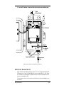
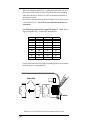
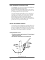
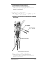
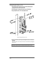
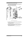
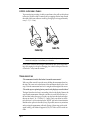
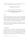
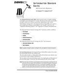
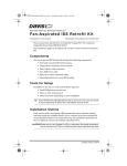
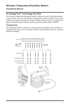
ANEMOMETER
TRANSMITTER KIT
INSTALLATION MANUAL
This manual describes how to install the Anemometer Transmitter Kit for Wireless Vantage ProTM. The kit enables you to connect the anemometer from your
Integrated Sensor Suite (ISS) to its own transmitter, so it can be located away
from the ISS and communicate directly with your console/receiver.
C OMPONENTS
The Anemometer Transmitter Kit includes the following components and
mounting hardware:
3-Volt
Lithium
Battery
Transmitter Shelter
1/4" x 1-1/2" Lag Screws
U-Bolts
4" Cable Tie
1/4" Flat Washers
1/4" Lock Washers
1/4" Hex Nuts
8" Cable Ties
Product # 6330
T OOLS
FOR
S ETUP
In addition to the kit, you will need some or all of the following materials:
✦ Adjustable wrench or 7/16" wrench
✦ Compass or local area map
✦ Ballpoint pen or paper clip (small pointed object of some kind)
✦ Drill and 3/16" (5 mm) drill bit (if mounting on a vertical surface)
If You Are Installing the ISS and the Anemometer Transmitter Kit at the
Same Time...
Install your ISS first, following the instructions in the ISS manual. However,
during the step “Disassembling the Radiation Shield,” DO NOT connect the
anemometer cable to the SIM. When you have mounted the rain collector side
of the ISS and are ready to mount the anemometer, follow the instructions in
this manual starting with “Preparing the Anemometer Transmitter” on page 4.
I NSTALLATION S TEPS
For ease of installation, please follow steps in the order presented.
✦ Remove the anemometer from its current location (if necessary), page 3
✦ Disconnect the anemometer from the ISS transmitter, page 3
✦ Unfasten and remove the anemometer, page 4
✦ Prepare the anemometer transmitter, page 4
✦ Insert the battery, page 4
✦ Plug the anemometer cable into the transmitter, page 4
✦ Set the transmitter ID, page 5
✦ Set ID on the anemometer transmitter using DIP switches, page 5
✦ Set the console to recognize the signals, page 7
✦ View current wind data, page 7
✦ (If you don’t see current wind readings, put your anemometer
transmitter in TEST mode, page 8.)
✦ Choose a location for the anemometer transmitter, page 9
✦ Test transmission from the proposed mounting location, page 10
✦ Mount the anemometer and transmitter shelter in the new location, page 10
✦ A note on securing cables, page 14
The most common anemometer problems and their causes are outlined in
“Troubleshooting” on page 14. For Technical Support, see “Contacting Davis
Instruments” on page 15.
Page 2
R EMOVING
THE
A NEMOMETER
FROM ITS
C URRENT L OCATION
This step assumes that your ISS is already mounted. If it is in a high location
such as a rooftop, please read through the instructions before climbing up, and
watch your balance while completing these tasks.
Disconnecting Anemometer from ISS Transmitter
On the rain collector side,
underneath the white
mounting base is the radiation shield. It consists of several white plastic plates. To
disconnect the anemometer
from the ISS transmitter,
remove the lower three
plates:
Mounting Base
Sensor
Interface
Module
(SIM)
1. Remove the wing nuts, lock
washers and flat washers.
2. Remove the first three plates of
the radiation shield.
You should now be able to
see the SIM.
Open Plate
3. Unplug the anemometer cable
from the receptacle labeled
“WIND” on the SIM.
Open Plate
Reassembling Radiation Shield
1. Slide the two open plates over
the threaded studs.
2. Slide the single closed plate over
the threaded studs.
Ease the antenna through the
antenna deployment hole.
3. Place a flat washer, lock washer
and wing nut over one of the
studs.
Tip: temporarily place a
wing nut on one of the studs
to hold the plates while you
place washers and a wing
nut on another stud.
Antenna
deployment
hole
Closed Plate
#8 Flat Washer
#8 Lock Washer
#8 Wing Nut
4. Finger-tighten the wing nut.
5. Repeat #3. and #4. until all three wing nuts are secure.
Removing the Anemometer from its Current Location
Page 3
If Your ISS is Mounted as a Single Unit (Both Sides Together on a Pole)
Unfasten the anemometer:
1. Remove the black rain collector cone from its base by rotating cone counter-clockwise
until its latches line up with openings in the base and you can lift it off.
It is much easier to reach the hex nuts with a wrench if you remove the rain
collector cone first.
2. Using an adjustable wrench or 7/16" wrench, remove the hex nuts and washers holding
the anemometer’s plastic mounting base on the pole.
Set the anemometer down for a moment.
3. Remove the hex nuts and washers holding the rain collector side on the pole.
Retrieve the U-bolt that was holding the anemometer.
4. Using the washers and hex nuts, fasten the rain collector side back onto the pole.
Flat washer goes on first, then lock washer, then hex nut.
5. Put the rain collector cone back on.
Rotate the cone clockwise until the latches slide into place.
If Your Anemometer is Mounted by Itself
Unfasten it: use an adjustable wrench or 7/16" wrench to remove the hex nuts
or lag screws.
P REPARING
THE
A NEMOMETER T RANSMITTER
The illustration on the following page shows the Sensor Interface Module, or
“SIM”, inside the transmitter shelter.
1. Insert the 3-volt lithium battery into the battery holder, matching the “+” sign on the
battery with the “+” sign on the SIM.
2. Push the end of the anemometer cable up through the square black grommet into the
transmitter shelter.
(Every Davis shelter has two of these grommets to provide weather-resistant
entrances for cables. In this case, use the grommet on the right.)
3. Plug the end of the anemometer cable into the receptacle labeled “WIND” on the SIM.
4. Using the 4" black plastic cable tie provided, secure the anemometer cable inside the
shelter.
Slide the cable tie through the cable tie mount, make a loop around the anemometer cable, and tighten.
Page 4
5. Locate the DIP switches. You will work with them during the next installation step.
3-Volt
Lithium Battery
DIP Switches
Cable Tie
Cable Tie
Mount
Square Black Grommets
Anemometer
Cable
SENSOR INTERFACE MODULE ON ANEMOMETER TRANSMITTER
S ETTING
THE
T RANSMITTER ID
Each wireless transmitting station must be set to one of eight transmitter IDs.
DIP switches #1, 2 and 3 on the SIM allow you to control the ID — the “channel” the station will transmit on. (DIP switch #4 is used for transmission testing, not for transmitter ID.)
The transmitter and receiver communicate with each other only when both are set to
the same ID.
Setting the Transmitter ID
Page 5
The factory default transmitter ID is ‘1’. Looking at the table below, you can see
that means the DIP switches are in the OFF position when each transmitting
station leaves the factory, whether it is an ISS, an anemometer transmitter, or
another kind of station.
Since the ISS is included with every Wireless Vantage Pro, the console/receiver
is set to find the ISS on ‘1’. Set the ID of your anemometer transmitter to its
own number.
Use a ballpoint pen or paper clip to toggle DIP switches #1, 2, and 3. The settings for transmitter IDs 1 – 8 are shown in the table below:
ID CODE
SWITCH 1
SWITCH 2
SWITCH 3
#1 (default)
#2
#3
#4
#5
#6
#7
#8
off
off
off
off
ON
ON
ON
ON
off
off
ON
ON
off
off
ON
ON
off
ON
off
ON
off
ON
off
ON
Use this table to ensure that each wireless transmitting station in your system is
broadcasting on its own transmitter ID.
Battery Holder
ON
1
2
3
4
DIP Switches
DIP SWITCHES IN TOP-RIGHT CORNER OF SIM (ILLUSTRATION HAS BEEN ENLARGED FOR CLARITY)
Page 6
Setting Console/Receiver(s) to Same ID
1. Put your console into Setup Mode — press and hold the DONE key and press the
DOWN arrow key.
The console will show you Screen 1: Transmitters. You should see the words:
“RECEIVING FROM...” and “STATION NO.” followed by the transmitter
IDs that your console detects. One of these should be the ID number you just
set on the anemometer transmitter. If you don’t see it, make sure the console
is within 10' of the transmitter, and verify that you set the DIP switches correctly. If you still don’t see it, go to “TEST mode” on the next page.
2. Press the DONE key to move on to Screen 2: Selecting Transmitters.
Setup Mode – Screen 2 is where you will set the console to recognize signals
on that ID as coming from an anemometer transmitter.
3. Press the LEFT or RIGHT arrow key, or the STATION key, to scroll through transmitter
IDs.
When you see the ID you chose for the anemometer, use the UP or DOWN
arrow keys to activate reception of that ID code. Make sure the screen shows
“ON”.
4. Press the GRAPH key to change the type of station assigned to that transmitter ID.
Press the GRAPH key until the word “WIND” appears.
5. To exit Setup Mode, press and hold the DONE key.
(See the Vantage Pro User’s Manual & Setup Guide: “Setup Mode – Screen 2:
Selecting Transmitters.”)
The console/receiver will display wind readings from one anemometer in
the compass rose. Once you set the ID code, it makes no visible difference that
the readings are now being sent by the anemometer transmitter instead of the
ISS transmitter.
Viewing Current Wind Data
You should now see wind direction and speed displaying in the compass rose
on the console screen. Press the WIND key if necessary to alternate between
speed and direction. Spin the wind cups. Turn the wind vane, and allow 5 seconds for the wind direction display to stabilize before moving it again.
Display of current wind data confirms communication between your anemometer transmitter and the console. Go on to “Choosing a Location for the
Anemometer Transmitter” on page 9.
Setting the Transmitter ID
Page 7
If You Do Not See Current Wind Readings
First, verify that the console/receiver is powered and is not in Setup Mode (exit
Setup Mode by pressing DONE key and holding it for a moment). Then, on the
transmitter, ensure that the anemometer sensor cable is firmly plugged into the
jack that is labeled “WIND” on the SIM. Check that the battery is properly
installed. Walk around the room with the console, standing for a few moments
in various locations to see if you are picking up signals.
If you don’t see wind readings no matter where you stand with the console,
put your anemometer transmitter in TEST mode.
TEST mode
DIP switch #4 on the SIM (see illustration on page 6) is the TEST DIP-switch.
Switch it to the ON position using a ball-point pen or paper clip. This puts the
transmitter in Test Mode. An LED indicator light will flash each time it transmits:
✦ The LED will immediately flash once to show that the light itself functions.
✦ Then it will flash each time the transmitter broadcasts a signal, which should be
every 2.5 seconds.
If the LED flashes only once and then remains dark, there is a problem with the
anemometer transmitter. See “Contacting Davis Instruments” on page 15.
If the LED flashes repeatedly but your console isn’t picking up a signal anywhere in the room, it could be related to one of the following causes:
1. The DIP switches were not correctly set on the transmitter.
Review the procedure on page 5.
2. The ID was not correctly set on the console/receiver.
Review the procedure on page 7.
3. Reception is being disrupted by RF (radio frequency) interference.
Interference has to be very strong to prevent the console from receiving a
signal while in the same room as the anemometer transmitter!
4. There is a problem with the console/receiver.
See “Contacting Davis Instruments” on page 15.
Note: Remember to turn the Test DIP switch OFF when you’re finished testing wireless transmission. If it is left ON, the blinking LED will reduce battery life significantly.
Page 8
C HOOSING
A
L OCATION
FOR THE
A NEMOMETER T RANSMITTER
Keep the following factors in mind as you choose a location for your anemometer and the transmitter shelter:
✦ Mount the anemometer at least 4' (1.2 m) above the roofline for accurate wind
readings.
As shown in the ISS manual, the anemometer can be mounted on a pole
or on a vertical surface such as a wooden post. It comes with 40' (12 m) of
cable to connect to the transmitter shelter.
✦ Mount the transmitter shelter nearby, with the solar panel facing the sun.
In the Northern Hemisphere, position the transmitter shelter with solar
panel facing south, for maximum sun exposure. (In the Southern Hemisphere, position the shelter with solar panel facing north.)
✦ If you need to increase the distance between your anemometer and the transmit-
ter shelter, use extension cables #7876 from Davis Instruments.
Please be aware that maximum wind speed reading decreases as the
total length of cable from the anemometer to the ISS increases. If this distance is greater than 240', maximum wind speed may be less than
100 mph.
Note: Not all cables are compatible with your Vantage Pro system. To be sure they will work, order
extension cables from your dealer or directly from Davis Instruments.
Range of Wireless Transmission
The range of wireless transmission depends on many factors. For the best
reception, position the transmitter shelter and your console/receiver as close
together as possible.
Range is up to 800' (250 m) in the line of sight, under optimal conditions. Typical range under most conditions is 150' to 500' (45 to 150 m), but this may be
reduced by walls, ceilings, trees, or foliage. Radio-frequency interference (RF)
can also reduce transmission distance. Cordless phones and ham radios are
common examples of RF interference.
A metal roof or other large metal structure can interfere with the signal (aluminum siding, a furnace with metal ducts, and your refrigerator are examples).
Sometimes transmission between wireless units is obscured by something you
cannot identify, or by some obstacle that you can’t work around. If necessary,
consider using Wireless Repeater #7624 or #7625 to strengthen the signal or
increase the distance between the anemometer transmitter and the console/receiver.
Choosing a Location for the Anemometer Transmitter
Page 9
T ESTING T RANSMISSION
FROM
P ROPOSED L OCATION
It is very important to test reception from the proposed location before permanently mounting the anemometer transmitter shelter.
Place the transmitter shelter at the intended mounting site, or have someone
hold it there, so you can walk around with the console/receiver for a few minutes. Rotating the antenna may help to improve reception.
Test wireless reception anywhere you might want to use or mount your console/receiver now or in the future. Take your time. If you aren’t picking up
strong signals where you intend to place your console, better to move the
transmitter shelter now than after it has been mounted. Experiment.
If you have irregular terrain in the area, it may interfere with the signal. For
example, if the transmitter is mounted downhill from the console/receiver, the
ground may block a wide angle of the transmitted signal.
M OUNTING
THE
A NEMOMETER T RANSMITTER
As shown in the ISS manual, the anemometer can be mounted either on a pole
or on a vertical surface such as a fencepost. Remember to mount it so the anemometer arm is extending northward. (Otherwise, you will need to re-orient
the wind vane. See Appendix C in your ISS manual for instructions.) The transmitter shelter also can be mounted on a pole or on a vertical surface.
Mounting Anemometer on a Pole
1. While holding the mounting base against the pole, place a U-bolt around the pole and
through the two holes in the base.
2. Place a flat washer, a split washer and a hex nut on each of the bolt ends.
1/4" Flat Washer
1/4" Lock Washer
1/4" Hex Nut
U-Bolt
MOUNTING ANEMOMETER ON A POLE
Page 10
3. Swivel the anemometer until the arm is pointing north.
4. Using an adjustable wrench or 7/16" wrench, tighten the nuts.
If the anemometer arm is not pointing north, follow the instructions in
Appendix C in your ISS manual.
Mounting Anemometer on a Vertical Surface
1. With a 3/16" (5 mm) drill bit, drill two holes approximately 2-1/8" (54 mm) apart. Use a
carpenter’s level to ensure the holes will be level.
2. Insert the 1/4" x 3" lag screws through the flat washers and the holes in the mounting
base into the post.
1/4" Flat Washers
1/4" x 3" Lag Screws
40' of Anemometer Cable
MOUNTING ANEMOMETER ON A VERTICAL SURFACE
3. Using an adjustable wrench or 7/16" wrench, tighten the lag screws.
If the anemometer arm is not pointing north, follow the instructions in
Appendix C in your ISS manual.
Mounting the Anemometer Transmitter
Page 11
Mounting Transmitter Shelter on a Pole
1. While holding the shelter against the pole, place a U-bolt around the pole and
through the two holes on at the top of the shelter.
2. Place a flat washer, a lock washer and a hex nut on each of the bolt ends.
3. Using an adjustable wrench or 7/16" wrench, tighten the nuts.
Lock
Flat Washer
Washer
Hex
Nut
U-Bolt
MOUNTING TRANSMITTER SHELTER ON A POLE
4. Place the second U-bolt around the pole and through the two holes at the bottom of
the shelter.
Put a flat washer, a lock washer, and a hex nut on each bolt end, and tighten
the hex nuts.
Note: Remember to position the shelter so the solar panel has maximum exposure to the sun.
Page 12
Mounting Transmitter Shelter on a Vertical Surface
1. With a 3/16" (5 mm) drill bit, drill two holes approximately 2" (50 mm) apart. Use a
carpenter’s level to ensure the holes will be level.
2. Drill two more holes 7-1/32" below the upper holes.
Flat
Washer
Lag
Screw
MOUNTING TRANSMITTER SHELTER ON A POST
3. Insert the 1/4" x 1-1/2" lag screws through the flat washers, and through the holes at
the top of the shelter into the post.
Using an adjustable wrench or 7/16" wrench, tighten the lag screws.
4. Insert the 1/4" x 1-1/2" lag screws through the flat washers, and through the holes at
the bottom of the shelter into the post.
Using an adjustable wrench or 7/16" wrench, tighten the lag screws.
Mounting the Anemometer Transmitter
Page 13
A N OTE
ON
S ECURING C ABLES
To prevent fraying or cutting of cables, secure them so they will not whip about
in the wind. Secure a cable to a metal pole by wrapping electrical tape around
them both. Make sure cables are secure by placing clips or ties approximately
every 3 – 5' (1 – 1.6 m).
Cable Tie
Cable Clip
Note: Do not use metal staples or a staple gun to secure cables. Metal staples—especially when
installed with a staple gun—have a tendency to cut the cables.
If you haven’t used the entire length of anemometer cable, secure the remaining coil by taping it to the pole, or hanging it on a hook on the post. Place the
coil at least 6" away from the antenna.
T ROUBLESHOOTING
“The anemometer head is tilted when I mount the anemometer.”
With your Allen wrench, loosen the screws holding the anemometer head on
the arm. (The screws are on the bottom of the anemometer head, by the wind
cups.) Turn the anemometer head so it is straight and then tighten the screws.
“The wind cups are spinning but my console only displays zero miles/hour.”
The signal from the wind cups is not making it back to the display. Remove the
cups from the anemometer and make sure there is a small silver disk next to
the steel shaft where the cups go. Put the cups back onto the shaft and adjust
them up or down 1/16 – 1/8 inch (1.5 – 3 mm). Check your cables for visible
nicks and cuts. Look for corrosion in the “WIND” jack on the Sensor Interface
Module and on splices in the cable (if any). If possible, remove any extensions
and try using the anemometer cable only. If none of these steps get the wind
speed working, call Technical Support at (510) 732-7814 to ask for a wind test
cable.
Page 14
“The wind direction is stuck on north, or displays dashes.”
It is likely that there is a short or break somewhere between the wind vane and
the display. Check your cables for visible nicks and cuts. Look for corrosion in
the “WIND” jack on the Sensor Interface Module and on splices in the cable (if
any). If possible, remove any extensions and try with the anemometer cable
only. If none of these steps get the wind direction working, call Technical Support at (510) 732-7814 to ask for a wind test cable.
“The wind cups don’t spin as fast as they should. (Or don’t spin at all!)”
Either the anemometer is located where wind is blocked by something, or there
is friction interfering with the cups’ rotation. Friction usually can be remedied
by the user — remove the wind cups and clear out any bugs or debris. Turn the
shaft the cups rotate on. If it feels gritty or stiff, call Technical Support at (510)
732-7814. DO NOT LUBRICATE THE SHAFT OR BEARINGS IN ANY WAY.
When replacing the cups, make sure they are not rubbing against any part of
the anemometer head.
“Wind readings aren’t what I expected them to be.”
Be very careful. Comparing to measurements from TV, radio, newspapers, or a
neighbor is NOT a valid method of verifying your readings. Davis Instruments
sensors are carefully tested at the factory. If you have questions, contact Technical Support.
C ONTACTING D AVIS I NSTRUMENTS
(510) 732-7814 for Technical Support, Monday – Friday, 7:00 a.m. – 5:30 p.m.
Pacific Time.
(800) 678-3669 Toll-Free Order Line, Monday – Friday, 7:00 a.m. – 5:30 p.m.
Pacific Time. Our customer service representatives can answer most questions
and assist you with your purchases.
(510) 732-9229 For callers outside the USA or Canada.
(510) 670-0589 Fax to Customer Service or Tech Support.
www.davisnet.com Copies of User Manuals are available on the “Support”
page. Watch for FAQs and other updates. Subscribe to the e-newsletter.
[email protected] E-mail to Technical Support.
[email protected] E-mail to Customer Service.
[email protected] General e-mail.
Note: Please do not return items to the factory for repair without prior authorization.
Contacting Davis Instruments
Page 15
S PECIFICATIONS
✦ Temperature range: –40 to 140° Fahrenheit (–40 to 60° Celsius)
✦ Wireless transmission frequency: 916.5 MHz
868.35 MHz for overseas version – Product # includes “XA”
✦ Transmitter ID codes: 8 user-selectable
✦ License: low power (less than 1 mW), no license required
✦ Primary power input: Solar power – Davis solar charger
✦ Secondary (backup) power:
✦ CR-123A 3-volt lithium battery
✦ Optional Vantage Pro AC power adapter
FCC Part 15 Class B Registration Warning
This equipment has been tested and found to comply with the limits for a class
B digital device, pursuant to Part 15 of the FCC Rules. These limits are
designed to provide reasonable protection against harmful interference in a
residential installation. This equipment generates, uses and can radiate radio
frequency energy and, if not installed and used in accordance with the instructions, may cause harmful interference to radio communications. However,
there is no guarantee that interference will not occur in a particular installation.
If this equipment does cause harmful interference to radio or television
reception, which can be determined by turning the equipment off and on, the
user is encouraged to try to correct the interference by one or more of the following measures:
✦ Reorient or relocate the receiving antenna.
✦ Increase the separation between the equipment and receiver.
✦ Connect the equipment into an outlet on a circuit different from that to which the
receiver is connected.
✦ Consult the dealer or an experienced radio/TV technician for help.
Changes or modifications not expressly approved in writing by Davis Instruments may void the user's authority to operate this equipment.
Product Numbers: 6330
Davis Instruments Part Number: 7395.137
Anemometer Transmitter Kit Installation Manual
Rev. A Manual (12/28/00)
This product complies with the essential protection requirements of the EC EMC Directve 89/336/EC.
Copyright ©2000 Davis Instruments Corp. All rights reserved.
3465 Diablo Avenue, Hayward, CA 94545-2778
510-732-9229 • Fax: 510-732-9188
E-mail: [email protected] • www.davisnet.com