1
Operating instructions
Topas A2/A4/A8Evolution
www.broncolor.com
1
Operating Instructions
broncolor
Topas A2/A4/A8 Evolution
Before use
We are very pleased you have chosen a broncolor Topas A power pack which is a high-quality
product in every respect. If used properly, it will render you many years of good service.
Please read the information contained in these operating instructions carefully. They contain
important details on the use, safety and maintenance of the appliance. Keep these operating
instructions in a safe place and pass them on to further users if necessary. Observe the safety
instructions.
Contents
Page
Topas A2/A4/A8 Evolution
2
Important safety instructions
3
Attention: Read before starting up the power pack
4
Controls and displays
5
1.
Application Topas A
7
2.
Start up
7
3.
Energy control
8
4.
Lamp base outlets
11
5.
Modelling light
11
6.
Release and remote control
13
7.
Flash ready signals visual/audible
14
8.
Setting additional functions
15
9.
Basic settings ex works
16
10. Protective facilities / Fault indication
18
11. Service/repair
19
12. Car battery converter
19
13. Lamp bases
19
14. Technical data
22
15. Topas A RFS
24
2
Important safety instructions
When using your studio flash equipment, basic safety precautions should always be followed,
including the following:
1.
Read and understand all instructions before using.
2.
Close supervision is necessary when any appliance is used near children. Do not leave
appliance unattended while in use.
3.
Care must be taken as burns can occur from touching hot parts.
4.
Do not operate appliance with a damaged cable or if the appliance has been dropped or
damaged – until it has been examined by a qualified service person.
5.
Position the cable so that it will not be tripped over, pulled, or contact hot surfaces.
6.
If an extension cable is necessary, a cable with a current rating at least equal to that of the
appliance should be used. Cables rated for less amperage than the appliance may
overheat. When using a cable reel, it must be completely unrolled before use to prevent
overheating of the cable.
7.
The power pack must be switched off while plugging in or unplugging the lamp base plugs.
8.
Always unplug appliance from electrical socket before cleaning and servicing and when in
use. Never jerk cable to pull plug from socket. Grasp plug and pull to disconnect.
9.
After use, let appliance as well as the connected lamp bases cool down completely before
putting away.
10. Put away and wind up the cables so that they do not touch hot parts of appliances and
lamps.
11. To reduce the risk of electric shock, do not immerse this appliance in water or other
liquids.
12. To reduce the risk of electric shock, do not disassemble this appliance, but take it to a
qualified service person when service or repair work is required. Incorrect reassembly can
cause electric shock when the appliance is used subsequently.
13. The use of an accessory attachment not recommended by the manufacturer may cause a
risk of fire, electric shock, or injury to persons.
14. Connect this appliance to an earthed socket.
3
Attention:
Read before starting up the power pack
-
Prior to replacing fuses, modelling lamps or flash tubes, discharge the power pack
and disconnect from power supply. Disconnect the lamp base from the power
pack.
-
These units are designed for use in dry conditions. Protect them from water and
from excessive exposure to dust.
-
The units are not suitable for use in an environment where there is a risk of
explosion.
-
The accessories mounted onto the lamp bases may heat up to high temperatures
under specific conditions. Handle with care!
-
With due allowance for heat radiation, lamp bases with more than 100 W modelling
light may be directed against inflammable surfaces only at a minimum distance of
1 m.
-
For safety reasons, never operate the lamps without the protecting glass
in place.
-
Flash light contains, similar to sunlight, a specific portion of UV light. The
undesirable side effects on skin and eyes are considerably reduced by using flash
tubes and glass covers with an UV coating. Without these or other protective
filters, use with extreme care when shooting.
-
Even when disconnected from the power supply, dangerous voltages may remain
inside the unit. For this reason units should be opened by trained personnel only.
-
Do not block the cooling louvers on the unit.
-
broncolor power packs and lamp bases meet an extremely high safety standard.
When connecting broncolor products to other manufacturers' products, integrated
safety measures may become ineffective. Due to different design features and
contact assignment of the lamp plugs of other brands, the user himself/herself may
even be at risk. We offer no guarantee and accept no liability for damages which
may be caused by this type of usage.
4
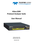
Controls and displays
1.
Mains switch
2.
Circuit breaker
3.
Keys for individual power distribution
4.
Photocell on/off
5.
IR receiver on/off
6.
Modelling light on/off
7.
Test key, ready light green
8.
Additional functions (aux)
9.
Display symmetrical power distribution
10.
Buzzer
11.
Slow charge
12.
Charging dimmer
13.
Operating mode modelling light
14.
IR receiver cell
15.
Digital power display per lamp
16.
Photocell
17.
Energy control up/down
18.
Sync socket
19.1
Lamp base outlet 1
19.2
Lamp base outlet 2
19.3
Lamp base outlet 3
19.4
Lamp base outlet 4
20.
Connection socket for mains (AC-line) cable
5
6
1.
Application Topas A
We are delighted that you have chosen the high quality product broncolor Topas A. With
proper care it will render you many years of good service.
This mains (AC-line) supplied studio flash unit is designed for professional photography.
For your safety, use a three-wire extension cable when required.
2.
Start up
2.1
Mains (AC-line) voltage
The power packs Topas A2 and Topas A4 automatically adapt to the respective mains
(AC-line) voltage between 240 V and 100 V. When the unit is operated on 100 V the
following limitations come into force:
- maximum flash energy Topas A2:
1200 J instead of 1600 J
- maximum flash energy Topas A4:
2400 J instead of 3200 J
- the flash duration is extended by about 20%
The Topas A8 Evolution power pack is designed only for the mains voltage 200 – 240
V.
Please check that your local mains voltage corresponds with the specifications on the
nameplate of the unit. Also ensure that the halogen modelling lamps (modelling light) of
the connected lamp bases correspond with the local mains voltage.
2.2
Earthed Mains (AC-line)
Connect unit to current supply always using an earthed mains plug.
2.3
Start up
Use the mains (AC-line) switch (1) to power-up unit. During the charging process the
digital power displays (15) of the two lamp outlets (1 and 2) flash, after which, they
become continuous. Additionally the green ready light (7) is lit.
7
3.
Energy control
3.1.
Variation of the energy
Use the "up/down" keys (17) to control the flash energy (flash intensity) on both lamp
outlets (1 and 2), respectively channels, within a range of 5 f-stops. Whole numbers are
full f-stop intervals, decimals indicate 1/10 f-stop steps.
Brief pressure on the "up/down" keys runs the power up (or down) by a 1/10 f-stop
interval, prolonged pressure by a full f-stop. Both energy displays (15) then blink until
charging or discharging has stabilized the new level.
3.1.1
Topas A2 / Topas A4
The maximum flash energy corresponds to value 10, the minimum to value 5. It is
possible to extend the control range of Topas A2 to 6 f-stops and of Topas A4 to 6,5 fstops (see chapter 9). Additionally the control range can be extended in the
asymmetrical mode with the following f-stops values by choosing the respective lamp
outlet: with Topas A2: +1,3 f-stops and with Topas A4 +1,7 f-stops.
3.1.2
Topas A8 Evolution
The maximum flash energy corresponds to value 10, the minimum to value 6. It is
possible to extend the control range by 5 f-stops (see chapter 9). Additionally the
control range can be extended in the asymmetrical mode by one f-stop by choosing the
respective lamp outlet or channel.
3.2
Symmetrical or individual energy distribution
Topas A power packs can be switched from symmetrical to individual (asymmetrical)
energy distribution. Press the keys "sym" or "asym" to select the required operating
mode (3). The green control lamp of the display "sym" (9) lights up when the unit is in
symmetrical operation. In the asymmetrical mode each lamp outlet is individually
controllable. The only exception is the Topas A8 Evolution, in which four lamp outlets
are controlled in pairs over two individual, controllable channels.
8
3.2.1
Topas A2 on mains (AC-line) 110 V-240 V
If the unit is set to individual energy distribution the power is divided between the two
lamp base outlets as follows:
Lamp outlet 1 = 60%.
The control range of the flash energy extends between 1000 J down to 30 J
(optional down to 15 J)
Lamp outlet 2 = 40%.
The control range of the flash energy extends between 600 J down to 20 J
(optional down to 10 J)
3.2.2
Topas A4 on mains (AC-line) 110 V - 240 V
If the unit is set to individual energy distribution the power is divided between the two
lamp base outlets as follows:
Lamp outlet 1 = 70%.
The control range of the flash energy extends between 2200 J down to 70 J
(optional down to 25 J)
Lamp outlet 2 = 30%.
The control range of the flash energy extends between 1000 J down to 30 J
(optional down to 10 J)
3.2.3
Topas A8 Evolution on mains (AC-line) 200 V -240 V
If the unit is set to individual energy distribution the power is divided between the two
lamp base outlets I and II (1) respectively III and IV (2):
Lamp base outlet 1:
- with one lamp on lamp base outlet I or II = 50%
- with two lamps on lamp base outlet I or II = 25% per outlet
Lamp base outlet 2:
- with one lamp on lamp base outlet III or IV = 50%
- with two lamps on lamp base outlet III or IV = 25% per outlet (optional down to 95 J)
9
The control range of the flash energy extends per channel:
a) when using one lamp base outlet:
from 3050 J down to 190 J (optional down to 95 J)
b) when using both lamp base outlets:
from 1525 J down to 95 J (optional down to 50 J) per lamp base
In asymmetrical mode, a maximum of 3050 J can be drawn from each lamp socket
respectively channel with Topas A8 Evolution. Consequently Topas A Evolution power
packs are in asymmetrical mode compatible with all broncolor lamp bases. Should the
total power pack energy of 6100 J be triggered from one individual lamp base, a Pulso
Twin lamp must be used which, in comparison with a Pulso 8 lamp, results in a shorter
flash duration.
If the power pack Topas A8 Evolution operates in symmetrical mode, the full power
pack energy of 6100 J can be drawn from any socket. This requires the use of a Pulso 8
lamp however. For safety reasons, smaller lamps are blocked in this operating mode.
The advantage of the Pulso 8 lamp in comparison with the Twin lamp is its single and
longer lamp cable, which is also suitable for large installations.
3.2.4
Operation Topas A2 on mains (AC-line) 100 V
If the unit is set to individual energy distribution the power is divided between the two
lamp base outlets as follows:
Lamp base outlet 1 = 60%.
The control range of the flash energy extends between 700 J down to 45 J
(optional down to 20 J)
Lamp base outlet 2 = 40%.
The control range of the flash energy extends between 500 J down to 30 J
(optional down to 15 J)
3.2.5
Operation Topas A4 on mains (AC-line) 100 V
If the unit is set to individual energy distribution the power is divided between the two
lamp base outlets as follows:
Lamp base outlet 1 = 70%.
The control range of the flash energy extends between 1700 J down to 105 J
(optional bis 55 J)
Lamp base outlet 2 = 30%.
The control range of the flash energy extends between 700 J down to 45 J
(optional bis 20 J)
10
3.2.6
Stabilisation of the colour temperature
The power packs Topas A2 and Topas A4 are equipped with a circuit providing an
approximate stabilisation of the colour temperature (CTC light). Thus, in symmetrical
operation, the colour temperature can be constantly maintained over a range of about 3
f-stops within +/- 150K.
4.
Lamp base outlets
The two lamp base outlets (19.1 / 19.2) of the Topas A2 / A4 are marked with the
numbers 1 and 2. The four lamp base outlets (19.1 / 19.2 / 19.3 / 19.4) of the Topas A8
Evolution are defined in pairs with the numbers 1 and 2 on the two channels. Each
outlet respectively channel can be switched on individually. The digital power display
(15) shows the flash energy of the respective lamp or channel.
The broncolor lamp assortment can be applied without limitations with Topas A2 and
Topas A4. Only the lamp bases Pulso 8 can be used with Topas A8 Evolution in
symmetrical mode.
5.
Modelling light
5.1
General
The "mod" key (6) switches on the modelling lamps for all connected lamp bases. When
switched on, the green LED lights up. Lamp bases also have an additional modelling
lamp switch.
Attention: Please note, the voltage of the modelling lamp must correspond with the
mains voltage.
5.2
Proportionality
The brightness of the modelling light can be set proportionally to the flash intensity. It is
explained in chapter 8, how to set the individual operating modes (modelling light
proportionality). To assure proportionality when operating units with different power
output ratings, the units have various proportionality levels. Proportionality is
guaranteed if the identical prop level has been set for all power packs. The higher the
digit, the brighter the modelling light.
The following operating modes are possible:
11
„P1“
Proportional modelling light with broncolor power packs up to 6400 J
(= setting ex works for Topas A8)
„P2“
Proportional modelling light with broncolor power packs up to 3200 J
(= setting ex works for Topas A4)
„P3“
Proportional modelling light with broncolor power packs up to 1600 J
(= setting ex works for Topas A2)
„P4/5“ If a power pack is operated at a low output level, the halogen modelling light will
be, as known, relatively weak and yellowish. To counteract this problem, the
Topas is equipped with two additional modelling light proportionality levels: P4
for 800 J and less, P5 for 400 J and less. Thus the brightness of the modelling
light can be increased.
„HI“
All lamp bases operate at full modelling light power independent of flash output.
This setting will allow video recordings using the modelling lamps.
„LO“
Lighting level is reduced for all lamps independent of the flash output to reduce
power consumption and extend the service life of the halogen lamps.
Pressing the "mod" key (6) for 2 seconds when the modelling lamp is on will give direct
access to the “HI” mode. To return to the previous mode briefly press "mod" again.
Highest possible proportionality settings when combining devices of different output:
Topas A2
Grafit A2
Nano 2
Mobil
Topas A2
Grafit A2
Nano 2
Mobil
Topas A4
Grafit A4
Nano A4
Topas A8 Evolution
Topas A4
Grafit A4
Nano A4
Topas A8 Evolution
P3
P2
P1
P2
P2
P1
P1
P1
P1
Example 1: A power pack Topas A2 is operated together with a power pack Topas A8
Evolution. The modelling light is proportional and most intense when both
are set to mode "prop1".
Example 2: A power pack Topas A4 is operated together with a Grafit A2. The
modelling light is proportional and highest possible when both are set to
mode "prop2".
12
5.3
Modelling light switch on lamp base
The switch on the lamp base permits individual lighting control with the modelling light.
To avoid damage to the lamp filament, we recommend, always to switch off the
modelling light before moving the lamp base.
6.
Release and remote control
The flash release is enabled when 75% of the selected energy is available. Please note,
however, that the ready indicator is activated only at 100% charge (chapter 7).
When triggering via the “cell” or infrared receiver (IR), ensure that the infrared receiver
of the device is not obstructed by obstacles.
6.1
Photocell (cell)
The photocell can be switched on or off by using the „cell“ (4). Is the function activated
the green LED lights up. After a flash series an active cell is blocked, and the green
LED lights up. By pressing the „cell" key, the block is cancelled.
When triggering via the “cell” or infrared receiver (IR), ensure that the infrared receiver
of the device is not obstructed by obstacles.
6.2
Infrared-receiver (ir)
The infrared receiver can be switched on and off by using the „ir“ (5) key. If the function
is activated the green LED lights up.
When triggering via the “cell” or infrared receiver (IR), ensure that the infrared receiver
of the device is not obstructed by obstacles.
6.3
Infrared flash release channel
You can trigger Topas A power packs from broncolor infrared transmitters. If a power
pack is triggered via infrared, the flash is released after a transmission delay of
1/1000 s.
13
6.4
RFS Interface
The RFS interface of the power packs Topas A in the RFS version can be switched
on/off. The procedure is described in chapter 9.
6.5
Remote control channels
The remote control can only be used with the power packs Topas A RFS and is effected
by radio over the separate channels (studio workstations). The procedure is described
in chapter 9.
6.6
Power pack addresses
The assignment of addresses by radio to each unit is only possible with the power
packs Topas A RFS. This allows individual operation within the same studio
workstation. The definition of the unit addresses is described in chapter 9.
6.7
Sync socket
Synchronous cables art. no. 34.111.00 or 34.112.00 may be plugged into the socket to
release flashes via cable.
6.8
„Test“ key
The key (7) allows manual release of the power pack (see chapter 7.1).
7.
Flash ready signals visual/audible
7.1
The visual ready signal
is the green LED at the "test" key (7). It lights up only when the unit is fully charged to
the set flash energy.
After a flash, the power display (15) of the occupied lamp base outlets blink and the
LED goes out and lights up again when the unit is fully charged once more.
14
7.2
The audible signal
("buzzer") sounds when the power capacitors are at 100% charge of the set flash
energy. It may be switched on or off (chapter 8).
7.3
Audible fault signal
When the flash discharge fails, a warning signal of approx. 3s duration will sound and
the display (15) of the respective lamp base will blink.
8.
Setting additional functions
The "aux" key (8) is used to select additional functions. Repeated actuation of the key
toggles through the following display modes:
- Select proportionality level of the modelling light
- Set DIM
- Set slow charging
- Set buzzer
- Return to standard display
LED “prop” blinks (13)
LED “dim” blinks (12)
LED “slow” blinks (11)
LED “buz” blinks (10)
no LED blinks
After the setting has been performed, the standard display can be re-activated by
pressing the „aux“ key (8) or automatically after a waiting time of 4 seconds.
To set the additional functions select the respective LED (example: "Set dim"). The
digital display 2 (15) will then show the actual value which can be changed with the
"up/down" key (17). If a setting is entered which deviates from the basic setting value,
the respective LED will remain lit as a reminder after the display returns to standard
(exception: function „prop“). If the unit is switched off and on again, it will be in the
"standard display" mode. Previously set additional functions are retained.
8.1
Set proportionality level of the modelling light (prop)
The proportionality level of the modelling light can be selected by a brief pressure on the
"up/down" key (17) of the lamp base switch 2. With repeated actuation of the key the
following modes can be set, each shown respectively on the digital display 2 (15): P1,
P2, P3, P4, P5, HI, LO.
15
8.2
Set charging dimmer (dim)
The dim function can be switched on or off (on/--) by briefly pressing the “up/down” key
(17) of lamp base outlet 2. If the dim function is switched on, the modelling light will
extinguish when charging takes place. This feature can be used as a visual flash
monitor and to reduce the current load on weak mains (AC-lines).
8.3
Set slow charge (slow)
In case of weak mains (AC-line) power supply lines, charging time may be extended to
approx. double the standard value. The slow charge mode is switched on or off (on/--)
by briefly pressing the “up/down” key (17) of the lamp base outlet 2.
8.4
Set buzzer (buz)
The ready buzzer sounds when the power capacitors are 100% charged up. The ready
buzzer is switched on or off (on/--) by briefly pressing the “up/down” key (17) of the lamp
base outlet 2. The alarm tone will remain audible even if the ready buzzer is switched
off.
8.5
Sequences (serial flashes)
This function is selected with a prolonged pressure (1 s) on the key “test” and it permits
to set a defined number of flash discharges from 1 to 8 (displays “n1” to “n8”). When the
function is activated, i.e. a value between “n1” and “n8” is selected, the digital display
no. 1 (15) shows alternately the selected value of flash energy and the sequence of
flashes. The function is de-activated by selecting the value “n0”. Returning to the former
operating mode, is effected by pressing the key “aux” (8).
9.
Basic settings ex works
The basic settings ex works can be viewed and in some instances changed with the
following procedure:
Switch the unit on. Simultaneously press the "mod" (7) and "aux" (8) keys for 5
seconds. Digital display 2 (15) shows the selected function number and digital display 1
(15) shows the actual setting. Both values can be changed with the "up"/"down" key
(17).
16
The LED array will blink “cell”-“ir”-“mod”-“test”-“sym” to indicate that you are in the
programming mode. In functions number 0 and 3, pressing the "up"/"down" key of the
digital display 1 (15) will toggle through the "prop", "dim" or "slow" green LED display in
order to show different parts of a multi-digit display.
Function number
0
1
2
3
4
5
6
7
8
Meaning and possible settings
Program version ("prop" is lit)
Program number ("dim" is lit)
Setting ex works: off
„on“: Extended control range of the flash energy. The detailed
values are specified in section 3.1 of chapter 3. The lowest fstop level exhibits greater tolerances with regard to colour and
repetitive precision. The flash release is not guaranteed with all
lamp base types.
Switch on/ off the RFS Interface:
Settings ex works:”off”
“off”: RFS Interface is switched off
“on”: RFS Interface is switched on
Flash counter: "slow" is lit: xxxxXX
"dim" is lit: xxXXxx
"prop" is lit: XXxxxx
Delivery date: Month
Delivery date: Year
Country code
Setting the studio workstation:
By pressing the keys „up/down“ (17) of the digital display
number 1 (15) you can select the workstation („01“ to „10“).
You can select up to 10 studio workstations.
Setting the power pack address:
By pressing the keys „up/down“ (17) of the digital display
number 1 (15) you can select the desired power pack address
(„01“ to „10“). Per studio workstation you can select up to 10
different unit addresses.
Return to normal operation by pressing the "aux" key or by switching off and on again the unit.
17
10. Protective facilities / Fault indication
10.1
Display "th"
If excessively high temperatures build up inside the unit despite the fan cooling effect,
the charge mode will be blocked for a certain period of time and a long audible signal
will be emitted.
During the cool-down period "th" shows on the display of lamp base outlet 2 (15). The
display of lamp base outlet 1 shows in "countdown" procedure the remaining duration of
the cooling process. The fan continues to operate, thus accelerating the cooling effect.
Attention: Do not switch off the power pack while it is cooling down. If the power
pack is switched off too early, it is likely, despite a long break, that only a few flashes
are possible when switching the unit on again, because the processor has not been
able to follow the entire cooling process.
10.2
Display "A1"
The unit is equipped with an automatic afterglow blockout. If the flash tube exhibits
afterglow (for example at the end of its service life), this blockout will block further
charging to prevent consequential damage. A1 will show on the display of lamp base
outlet 2 (15). In this status, the ready lamp is no longer green. The block can be
cancelled by switching the unit off and on again.
10.3
Circuit breaker
In the event of an electrical malfunction, the circuit breaker (2) will automatically
disconnect the power pack from the power source. The unit can be restarted by
pressing the circuit breaker button. If it disconnects again immediately, the power pack
must be serviced by authorized service staff.
10.4
Monitoring of the modelling light
If the power packs Topas A2 and Topas A4 are connected to 200-240 V mains (AC-line)
voltage, after previously having been operated on 100-120 V mains voltage, they will
release an audible signal and the modelling light will blink at a safely reduced voltage.
This function serves as a reminder that the modelling lamp must be exchanged, and
also to protect against bursting of the lamps. Switch the unit off and on again to return to
standard operation.
10.5
Acoustic trigger control
At the end of their service life the flash tubes often show flash trigger failure. This fault is
indicated by the unit with an intermittent acoustic signal. The sound disappears, when
the flash tube flashes again correctly or the unit is switched off.
18
Note:
With Topas A8 Evolution the acoustic flash trigger control is only activated, if
per channel one of the two lamp base outlets are occupied.
11. Service/repair
Your broncolor power pack is a precision device which will work for many years without
malfunctions if you take proper care of it. If malfunctions do arise, please do not attempt
to open the unit to repair it yourself. Even when the unit is shut off, dangerous voltages
may remain within the interior of the device. Leave service and repairs to our broncolor
repair service.
12. Car battery converter
If no mains (AC-line) power is available, use the 12 V/220 V car battery converter.
The modelling light cannot be used in this mode (excessive load on battery) and must
be removed.
-
Switch off modelling light and disconnect the lamp base from the power pack.
Connect converter to the 12-volt car battery with the + and – terminal clamps.
Connect unit to converter; switch on converter and unit.
After flash work, switch off converter during pauses. Charge battery if needed by
allowing the car engine to run.
- 1 Topas A can be connected to the converter.
13. Lamp bases
The following information applies to Pulso, Unilite, Primo and Picolite lamp bases.
13.1
Replacing flash tubes
Prior to any change of the flash tube, the lamp base must be disconnected from the
power pack!
19
Lamp bases use plug-in flash tubes.
The Pulso, Primo and Unilite flash tubes 1600 J normally have the UV coating directly
on the flash tube. In this case an uncoated protecting glass has to be used. The
protecting glasses as well as the flash tubes 1600 J are available in the versions „UVE
coated“ (5500 K) as well as uncoated (5900 K). For this reason the lamp bases Pulso,
Primo and Unilite can also be fitted with uncoated flash tubes and coated protecting
glasses.
The flash tubes 3200 J for Pulso, Primo and Unilite lamp bases as well as for the small
lamp Picolite are, for thermal reasons, only available uncoated. Therefore an UV coated
protecting glass must be used with these lamp bases.
The flash tube and protection glass of the Pulso 8 lamp base form one module.
13.1.1 Pulso / Primo and Unilite lamp bases up to 3200J
To change the flash tube, carefully pull off the protecting glass. Pull straight, without
tilting. Lamp bases manufactured from 1996 on, have the upper of the three springs
holding the protection glass differently shaped to provide a better hold. When removing
the protection glass it is necessary to first release the glass from the bottom spring.
Release the contact spring (only Primo lamp) and again be sure to pull the flash tube
straight along the lamp base axis.
When inserting the tube check that the ceramic base is fully pushed back in, and that for
the Primo lamp bases the contact spring rests on the internal ignition. Finally, the
protecting glass must be re-inserted before the modelling lamp and flash tube. It is held
by three springs. As Primo lamp bases can be used with 1600 J tubes as well as 3200 J
tubes, a corresponding warning sticker is supplied with each flash tube which must be
affixed to the lamp plug when inserting the tube.
13.1.2 Pulso 8 Leuchte
The flash tube is available only with integrated protecting glass. When exchanging the
flash tube or replacing the modelling lamp, hold the flash tube carefully on the protecting
glass and pull out in an axial direction. When inserting the flash tube check that the
ceramic base is fully pushed back in.
13.1.3 Small lamp Picolite
This small lamp has a plug-in flash tube with spring fastener. For thermal reasons the
UV-coating is on the protecting glass. The protecting glass is available in the versions
"UVE coated" (5500 K) and "UVE matt coated" (5500 K).
To change the flash tube release the spring-ring and remove the protecting glass. The
flash tube must be pulled out straight along the lamp base axis. When inserting the tube
be sure that it is fully pushed in. Finally, replace the protecting glass and fasten with the
spring-ring.
20
13.2
Changing the halogen lamp
The halogen lamps are also plug-in or screw-in. Taking the service life into
consideration, the halogen lamp should not be handled with bare hands. Exchange of
the halogen lamp is practically identical to that of the flash tube.
The Pulso G, Unilite, Primo and Picolite lamp base can be operated on the local mains
(AC-line) voltage (100-240 V) when a halogen lamp is used which corresponds to the
voltage.
13.3
Cooling fan
A cooling fan in the lamp base cools the flash tube and modelling lamp. It also runs
when the modelling lamp is turned off.
13.4
Thermal protection
The lamp bases are fitted with an automatic thermal protection. Should the lamp base
overheat (e.g. by impeding the flow of cooling air), the modelling light is shut off.
Nevertheless you may continue producing flashes. The Picolite, however, has an
additional thermal protection which limits the number of flashes.
13.5
Lamp base plugs
The lamp base plugs and sockets have mechanical interlocks to prevent inadvertent
disconnection. When plugging in, ensure that those interlocks engage completely. To
unplug, push down the locking spring under the cable guide and lift out the plug. The
power pack must be switched off to plug-in and to unplug.
13.6
Reflectors
Pulso, Unilite and Primo lamp bases have a bayonet fitting to attach reflectors. The
Picolite small lamp has a built-in reflector.
13.7
Fuses
Only sand-filled fuses of the type indicated on the type plate may be used; otherwise the
halogen lamp may burst.
21
14. Technical data
Flash energy
F-stop at distance of 2m 100
ISO,reflector P70
Flash duration t 0.1 (t 0.5) with
230 V / 120 V
Charging time (for 100% of
selected energy)
Ready display
Lamp base outlets
Power output distribution
Controls
Control range of flash energy
(Japan: ½ f-stop less)
Maximum asymmetry
Modelling light
Flash release
Release control
Additional function
No. of sync sockets
Stabilized flash voltage
Standards
Power requirements
Dimensions (L x B x H)
Weight kg
Topas A2
Topas A4
1600J (Japan 1200J)
64 2/10
3200J (Japan 2400J)
90 2/10
1600J: 1/300s (1/1000s)
3200J: 1/150s (1/600s)
1000J: 1/400s (1/1300s)
2200J: 1/180s (1/800s)
600J: 1/500s (1/1600s)
1000J: 1/250s (1/1300s)
230V, 120 V: 0,4 - 1,8s
230V, 120 V: 0,4 - 3,4s
100 V: 0,5 - 2s
100 V: 0,5 - 4s
Can be switched to slow charge mode
Automatic adaptation to the respective mains (AC-line) voltage
Visual and audible (can be switched off), signals when 100% of selected
energy is reached
2
2
Symmetrical and individual variable (asymmetrical)
Dust and scratch proof, fully illuminated silicone keyboard and LED display.
Topas A2: 5 f-stops in 1/10 (1:32) intervals
Switchable to 6 f-stops (1:64)
Topas A4: 5 f-stops in 1/10 (1:32) intervals
Switchable to 6.5 f-stops (1:90)
By selecting the corresponding lamp outlet in asymmetrical mode additionally
1.3 f-stops with Topas A2, 1.7 f-stops with Topas A4
6.2 f-stops
5.6 f-stops
Halogen max. 2 x 650 W at 200-240 V
Halogen max. 2 x 300 W at 100-120 V
Proportional to flash energy and „full“ and „low“ settings. Proportionality
adjustable to other broncolor power packs and compact units and their various
output ranges.
Manual release button, photocell (can be switched off), infrared receiver (can
be switched off), sync cable, FCM 2, FCC, IRX2, IRQ
Visual: Dim function of the modelling light, acoustic: buzzer
Sequences (flash series)
2
+/- 1%
UL 122, EC-standards 73/23, 89/336 and 99/5
200-240 V / 50 Hz:
110-120 V / 50-60 Hz:
100 V / 50 Hz:
280 x 162,7 x 272 mm
5,8
22
10 A
16 A
16 A
280 x 162,7 x 322 mm
8
Technical data (continuation)
Flash energy
F-stop at distance of 2m 100
ISO, reflector P65
Flash duration t 0.1 (t 0.5)
with 230 V
Charging time (for 100% of
selected energy)
Topas A8 Evolution with
lamp base Pulso G, Primo,
Unilite or Pulso Twin
Topas A8 Evolution with
Pulso lamp base 8
2 x 3050 J (4 x 1525 J)
128 (Pulso Twin)
6100 J
128
3050J: 1/150s (1/600s)
1525J: 1/300s (1/1200s)
0,5 – 5,2s
6100J: 1/50s (1/230s)
0,5 – 5,2s
Release control
Additional function
No. of sync. sockets
Stabilized flash voltage
Standards
Can be switched to low charge mode
Topas A8 Evolution is only designed for a mains voltage of 200 – 240 V.
Visual and audible (can be switched off), signals when 100% of selected
energy is reached
4
Symmetrical and individual variable (asymmetrical)
Dust and scratch proof, fully illuminated silicone keyboard and LED display.
4 f-stops in 1/10 (1:16) intervals
can be switched to 5 f-stops (1:32).
By selecting the corresponding lamp outlet in asymmetrical mode additionally
1 f-stop
5 f-stops
Halogen max. 4 x 650 W at 200-240 V
Proportional to flash energy and „full“ and „low“ settings. Proportionality
adjustable to other broncolor power packs and compact units and their various
output ranges.
Manual release button, photocell (can be switched off), infrared receiver (can
be switched off), sync cable, FCM 2, FCC, IRX2, IRQ
Visual: Dim function of the modelling light, acoustic: buzzer
Sequences (flash series)
2
+/- 1%
UL 122, EC-standards 73/23, 89/336 and 99/5
Power requirements
Dimensions (L x B x H)
Weight kg
200-240 V / 50 Hz:
280 x 162,7 x 446 mm
15,6
Ready display
Lamp base outlets
Power output distribution
Controls
Control range of flash energy
Maximum asymmetry
Modelling light
Flash release
10 A
Subject to change in the interest of product enhancement.
23
15. Topas A RFS
The power packs Topas A are also available as a unit version with integrated 10
channel RFS Interface (Radio Frequency System). Each channel (studio) can control up
to 10 units. This interface allows remote control respectively flash release by radio via
the transmitter RFS as well as by means of a transceiver RFS via PC or Macintosh
computer. When controlling via screen, 4 storage spaces for different lighting situations
are at your disposal.
14.1
Modification to Topas A RFS
There is the possibility to modify Topas A power packs later on with a RFS interface.
The modification will be made by the customer service centre of our broncolor agency in
your country.
14.2
Topas A PLUS
Because of the laws in some countries, the use of the broncolor radio system is not
allowed. Therefore the power packs Topas A are also available in the version Topas A
Plus (that means with cable remote control). Besides the cable connection between the
power pack and the computer, the application with RFS is almost identical.
Attention:
There is no camera transmitter available for Topas A Plus !
Technical data
Topas A RFS
Flash release
Topas A plus
Transmitter RFS, transceiver RFS Analogue chapter 14
(besides the options in chapter 14)
Remote control
With integrated 10 channel RFS With integrated interface for the
interface (Radio Frequency System) remote control of the unit by cable
for the remote control of the unit by from PC or Macintosh computer. Each
radio via transceiver RFS from PC- channel (Studio) can control up to 10
or Macintosh computer. Each units.
channel (Studio) can control up to 10
units.
Operational distance outdoors Up to 50 m
Length of the connection cable from the
computer to the unit:
5m
Length of the connection cable between
the units:
2,5 m
Operational distance in closed Up to 30 m
See above
rooms
Range
Up to 300 m
See above
Number of sync sockets
1 (instead of the second sync socket 1 (the second sync socket is configured
there is the radio antenna)
as connection for the computer
cable)
24
Technical data (continuation)
Standards
UL 122, EC-standards 73/23, 89/336 und 99/5
ERM EN 300 220-1,-3
EMC EN 301 489-1,-3
EN 60950
EN 50371
FCC Part 15
This device complies with part 15 of the FCC Rules. Operation is subject
to the following two conditions:
(1) This device may not cause harmful interference and
(2) This device must accept any interference received, including
interference that may cause undesired operation.
Changes or modifications to this unit not expressly approved by the
party responsible for compliance could void the user’s authority to
operate the equipment.
Subject to change in the interest of product enhancement.
25
Printed in Germany 07/04
Bron Elektronik AG
CH-4123 Allschwil
Schweiz (Switzerland)
26